EP2055367A2 - Abgasreinigungskatalysator und zugehöriges Herstellungsverfahren - Google Patents
Abgasreinigungskatalysator und zugehöriges Herstellungsverfahren Download PDFInfo
- Publication number
- EP2055367A2 EP2055367A2 EP20090001627 EP09001627A EP2055367A2 EP 2055367 A2 EP2055367 A2 EP 2055367A2 EP 20090001627 EP20090001627 EP 20090001627 EP 09001627 A EP09001627 A EP 09001627A EP 2055367 A2 EP2055367 A2 EP 2055367A2
- Authority
- EP
- European Patent Office
- Prior art keywords
- compounds
- noble metal
- exhaust gas
- metal particles
- gas purifying
- Prior art date
- Legal status (The legal status is an assumption and is not a legal conclusion. Google has not performed a legal analysis and makes no representation as to the accuracy of the status listed.)
- Ceased
Links
- 239000003054 catalyst Substances 0.000 title claims abstract description 185
- 238000004519 manufacturing process Methods 0.000 title claims description 10
- 150000001875 compounds Chemical class 0.000 claims abstract description 256
- 229910000510 noble metal Inorganic materials 0.000 claims abstract description 225
- 239000002923 metal particle Substances 0.000 claims abstract description 163
- 229910052761 rare earth metal Inorganic materials 0.000 claims abstract description 31
- 230000015271 coagulation Effects 0.000 claims abstract description 21
- 238000005345 coagulation Methods 0.000 claims abstract description 21
- 239000002131 composite material Substances 0.000 claims abstract description 21
- 229910052784 alkaline earth metal Inorganic materials 0.000 claims abstract description 17
- 229910052783 alkali metal Inorganic materials 0.000 claims abstract description 16
- 150000001340 alkali metals Chemical class 0.000 claims abstract description 16
- 239000000843 powder Substances 0.000 claims description 117
- 239000002585 base Substances 0.000 claims description 38
- 239000011148 porous material Substances 0.000 claims description 22
- 229910052684 Cerium Inorganic materials 0.000 claims description 15
- 239000011163 secondary particle Substances 0.000 claims description 14
- 229910052763 palladium Inorganic materials 0.000 claims description 12
- 229910052697 platinum Inorganic materials 0.000 claims description 11
- 229910052746 lanthanum Inorganic materials 0.000 claims description 9
- 229910052726 zirconium Inorganic materials 0.000 claims description 9
- 229910052703 rhodium Inorganic materials 0.000 claims description 8
- 229910052788 barium Inorganic materials 0.000 claims description 7
- 238000003801 milling Methods 0.000 claims description 7
- 238000001179 sorption measurement Methods 0.000 claims description 7
- 229910052777 Praseodymium Inorganic materials 0.000 claims description 6
- 238000005245 sintering Methods 0.000 claims description 6
- 229910052779 Neodymium Inorganic materials 0.000 claims description 4
- 238000004458 analytical method Methods 0.000 claims description 3
- 229910052792 caesium Inorganic materials 0.000 claims description 3
- 229910052791 calcium Inorganic materials 0.000 claims description 3
- 229910052749 magnesium Inorganic materials 0.000 claims description 3
- 229910052700 potassium Inorganic materials 0.000 claims description 3
- 229910052701 rubidium Inorganic materials 0.000 claims description 3
- 229910052708 sodium Inorganic materials 0.000 claims description 3
- 229910052712 strontium Inorganic materials 0.000 claims description 3
- 150000001342 alkaline earth metals Chemical class 0.000 abstract 1
- 239000007789 gas Substances 0.000 description 91
- 241000264877 Hippospongia communis Species 0.000 description 87
- KDLHZDBZIXYQEI-UHFFFAOYSA-N Palladium Chemical compound [Pd] KDLHZDBZIXYQEI-UHFFFAOYSA-N 0.000 description 75
- PNEYBMLMFCGWSK-UHFFFAOYSA-N aluminium oxide Inorganic materials [O-2].[O-2].[O-2].[Al+3].[Al+3] PNEYBMLMFCGWSK-UHFFFAOYSA-N 0.000 description 56
- 239000002002 slurry Substances 0.000 description 48
- 230000000052 comparative effect Effects 0.000 description 45
- 239000002245 particle Substances 0.000 description 42
- 229910002651 NO3 Inorganic materials 0.000 description 36
- NHNBFGGVMKEFGY-UHFFFAOYSA-N Nitrate Chemical compound [O-][N+]([O-])=O NHNBFGGVMKEFGY-UHFFFAOYSA-N 0.000 description 36
- 238000012360 testing method Methods 0.000 description 36
- 229910001593 boehmite Inorganic materials 0.000 description 35
- FAHBNUUHRFUEAI-UHFFFAOYSA-M hydroxidooxidoaluminium Chemical compound O[Al]=O FAHBNUUHRFUEAI-UHFFFAOYSA-M 0.000 description 35
- 230000000694 effects Effects 0.000 description 34
- 238000010304 firing Methods 0.000 description 31
- 230000003197 catalytic effect Effects 0.000 description 29
- 239000000203 mixture Substances 0.000 description 29
- 239000010948 rhodium Substances 0.000 description 26
- BASFCYQUMIYNBI-UHFFFAOYSA-N platinum Chemical compound [Pt] BASFCYQUMIYNBI-UHFFFAOYSA-N 0.000 description 23
- QVGXLLKOCUKJST-UHFFFAOYSA-N atomic oxygen Chemical compound [O] QVGXLLKOCUKJST-UHFFFAOYSA-N 0.000 description 20
- 239000002105 nanoparticle Substances 0.000 description 20
- 239000001301 oxygen Substances 0.000 description 20
- 229910052760 oxygen Inorganic materials 0.000 description 20
- 238000001035 drying Methods 0.000 description 16
- 238000002360 preparation method Methods 0.000 description 15
- QTBSBXVTEAMEQO-UHFFFAOYSA-M Acetate Chemical compound CC([O-])=O QTBSBXVTEAMEQO-UHFFFAOYSA-M 0.000 description 12
- 239000004215 Carbon black (E152) Substances 0.000 description 11
- 229930195733 hydrocarbon Natural products 0.000 description 11
- 150000002430 hydrocarbons Chemical class 0.000 description 11
- 238000000034 method Methods 0.000 description 11
- 229910000422 cerium(IV) oxide Inorganic materials 0.000 description 10
- MWUXSHHQAYIFBG-UHFFFAOYSA-N Nitric oxide Chemical compound O=[N] MWUXSHHQAYIFBG-UHFFFAOYSA-N 0.000 description 9
- CETPSERCERDGAM-UHFFFAOYSA-N ceric oxide Chemical compound O=[Ce]=O CETPSERCERDGAM-UHFFFAOYSA-N 0.000 description 9
- 230000001629 suppression Effects 0.000 description 9
- MCMNRKCIXSYSNV-UHFFFAOYSA-N Zirconium dioxide Chemical compound O=[Zr]=O MCMNRKCIXSYSNV-UHFFFAOYSA-N 0.000 description 8
- 238000005259 measurement Methods 0.000 description 8
- 230000004913 activation Effects 0.000 description 7
- 239000011248 coating agent Substances 0.000 description 7
- 238000000576 coating method Methods 0.000 description 7
- 239000011246 composite particle Substances 0.000 description 7
- 230000003247 decreasing effect Effects 0.000 description 7
- 239000000243 solution Substances 0.000 description 7
- 239000003513 alkali Substances 0.000 description 6
- 230000000087 stabilizing effect Effects 0.000 description 6
- 238000003860 storage Methods 0.000 description 6
- KSSJBGNOJJETTC-UHFFFAOYSA-N COC1=C(C=CC=C1)N(C1=CC=2C3(C4=CC(=CC=C4C=2C=C1)N(C1=CC=C(C=C1)OC)C1=C(C=CC=C1)OC)C1=CC(=CC=C1C=1C=CC(=CC=13)N(C1=CC=C(C=C1)OC)C1=C(C=CC=C1)OC)N(C1=CC=C(C=C1)OC)C1=C(C=CC=C1)OC)C1=CC=C(C=C1)OC Chemical compound COC1=C(C=CC=C1)N(C1=CC=2C3(C4=CC(=CC=C4C=2C=C1)N(C1=CC=C(C=C1)OC)C1=C(C=CC=C1)OC)C1=CC(=CC=C1C=1C=CC(=CC=13)N(C1=CC=C(C=C1)OC)C1=C(C=CC=C1)OC)N(C1=CC=C(C=C1)OC)C1=C(C=CC=C1)OC)C1=CC=C(C=C1)OC KSSJBGNOJJETTC-UHFFFAOYSA-N 0.000 description 5
- 239000007864 aqueous solution Substances 0.000 description 5
- 238000011156 evaluation Methods 0.000 description 5
- UEGPKNKPLBYCNK-UHFFFAOYSA-L magnesium acetate Chemical compound [Mg+2].CC([O-])=O.CC([O-])=O UEGPKNKPLBYCNK-UHFFFAOYSA-L 0.000 description 5
- 239000002243 precursor Substances 0.000 description 5
- UGFAIRIUMAVXCW-UHFFFAOYSA-N Carbon monoxide Chemical compound [O+]#[C-] UGFAIRIUMAVXCW-UHFFFAOYSA-N 0.000 description 4
- QCWXUUIWCKQGHC-UHFFFAOYSA-N Zirconium Chemical compound [Zr] QCWXUUIWCKQGHC-UHFFFAOYSA-N 0.000 description 4
- 229910002091 carbon monoxide Inorganic materials 0.000 description 4
- 238000006243 chemical reaction Methods 0.000 description 4
- 230000001965 increasing effect Effects 0.000 description 4
- 239000000126 substance Substances 0.000 description 4
- GRYLNZFGIOXLOG-UHFFFAOYSA-N Nitric acid Chemical compound O[N+]([O-])=O GRYLNZFGIOXLOG-UHFFFAOYSA-N 0.000 description 3
- 238000004364 calculation method Methods 0.000 description 3
- 239000013078 crystal Substances 0.000 description 3
- 230000006866 deterioration Effects 0.000 description 3
- 239000000463 material Substances 0.000 description 3
- 229910017604 nitric acid Inorganic materials 0.000 description 3
- 239000002994 raw material Substances 0.000 description 3
- 241000894007 species Species 0.000 description 3
- 150000003623 transition metal compounds Chemical class 0.000 description 3
- 229910004625 Ce—Zr Inorganic materials 0.000 description 2
- GWEVSGVZZGPLCZ-UHFFFAOYSA-N Titan oxide Chemical compound O=[Ti]=O GWEVSGVZZGPLCZ-UHFFFAOYSA-N 0.000 description 2
- 239000012190 activator Substances 0.000 description 2
- 230000008901 benefit Effects 0.000 description 2
- 238000002485 combustion reaction Methods 0.000 description 2
- 229910052878 cordierite Inorganic materials 0.000 description 2
- JSKIRARMQDRGJZ-UHFFFAOYSA-N dimagnesium dioxido-bis[(1-oxido-3-oxo-2,4,6,8,9-pentaoxa-1,3-disila-5,7-dialuminabicyclo[3.3.1]nonan-7-yl)oxy]silane Chemical compound [Mg++].[Mg++].[O-][Si]([O-])(O[Al]1O[Al]2O[Si](=O)O[Si]([O-])(O1)O2)O[Al]1O[Al]2O[Si](=O)O[Si]([O-])(O1)O2 JSKIRARMQDRGJZ-UHFFFAOYSA-N 0.000 description 2
- 238000006073 displacement reaction Methods 0.000 description 2
- 238000005538 encapsulation Methods 0.000 description 2
- 230000002708 enhancing effect Effects 0.000 description 2
- 229910052751 metal Inorganic materials 0.000 description 2
- 239000002184 metal Substances 0.000 description 2
- 239000011859 microparticle Substances 0.000 description 2
- UJVRJBAUJYZFIX-UHFFFAOYSA-N nitric acid;oxozirconium Chemical compound [Zr]=O.O[N+]([O-])=O.O[N+]([O-])=O UJVRJBAUJYZFIX-UHFFFAOYSA-N 0.000 description 2
- 150000002910 rare earth metals Chemical class 0.000 description 2
- 238000004088 simulation Methods 0.000 description 2
- 229910052723 transition metal Inorganic materials 0.000 description 2
- 150000003624 transition metals Chemical class 0.000 description 2
- 229910052727 yttrium Inorganic materials 0.000 description 2
- BWJHJLINOYAPEG-HOTGVXAUSA-N 8-chloro-6-[(6-chloropyridin-3-yl)methyl]-3-[(1S,2S)-2-hydroxycyclopentyl]-7-methyl-2H-1,3-benzoxazin-4-one Chemical compound ClC1=C(C(=CC=2C(N(COC=21)[C@@H]1[C@H](CCC1)O)=O)CC=1C=NC(=CC=1)Cl)C BWJHJLINOYAPEG-HOTGVXAUSA-N 0.000 description 1
- 229910017947 MgOx Inorganic materials 0.000 description 1
- 230000005540 biological transmission Effects 0.000 description 1
- 230000009172 bursting Effects 0.000 description 1
- 230000000536 complexating effect Effects 0.000 description 1
- 229940125782 compound 2 Drugs 0.000 description 1
- 238000012790 confirmation Methods 0.000 description 1
- 238000007796 conventional method Methods 0.000 description 1
- RKTYLMNFRDHKIL-UHFFFAOYSA-N copper;5,10,15,20-tetraphenylporphyrin-22,24-diide Chemical compound [Cu+2].C1=CC(C(=C2C=CC([N-]2)=C(C=2C=CC=CC=2)C=2C=CC(N=2)=C(C=2C=CC=CC=2)C2=CC=C3[N-]2)C=2C=CC=CC=2)=NC1=C3C1=CC=CC=C1 RKTYLMNFRDHKIL-UHFFFAOYSA-N 0.000 description 1
- 238000005516 engineering process Methods 0.000 description 1
- 230000007613 environmental effect Effects 0.000 description 1
- 238000002474 experimental method Methods 0.000 description 1
- 230000009970 fire resistant effect Effects 0.000 description 1
- 239000000446 fuel Substances 0.000 description 1
- 238000005470 impregnation Methods 0.000 description 1
- 238000011068 loading method Methods 0.000 description 1
- 238000012423 maintenance Methods 0.000 description 1
- 229910044991 metal oxide Inorganic materials 0.000 description 1
- 150000004706 metal oxides Chemical class 0.000 description 1
- PLDDOISOJJCEMH-UHFFFAOYSA-N neodymium oxide Inorganic materials [O-2].[O-2].[O-2].[Nd+3].[Nd+3] PLDDOISOJJCEMH-UHFFFAOYSA-N 0.000 description 1
- 231100000572 poisoning Toxicity 0.000 description 1
- 230000000607 poisoning effect Effects 0.000 description 1
- 239000011164 primary particle Substances 0.000 description 1
- 230000008569 process Effects 0.000 description 1
- MHOVAHRLVXNVSD-UHFFFAOYSA-N rhodium atom Chemical compound [Rh] MHOVAHRLVXNVSD-UHFFFAOYSA-N 0.000 description 1
- 150000003839 salts Chemical class 0.000 description 1
- 238000004611 spectroscopical analysis Methods 0.000 description 1
- 238000000859 sublimation Methods 0.000 description 1
- 230000008022 sublimation Effects 0.000 description 1
- 231100000331 toxic Toxicity 0.000 description 1
- 230000002588 toxic effect Effects 0.000 description 1
- 230000007704 transition Effects 0.000 description 1
Images


Classifications
-
- B—PERFORMING OPERATIONS; TRANSPORTING
- B01—PHYSICAL OR CHEMICAL PROCESSES OR APPARATUS IN GENERAL
- B01D—SEPARATION
- B01D53/00—Separation of gases or vapours; Recovering vapours of volatile solvents from gases; Chemical or biological purification of waste gases, e.g. engine exhaust gases, smoke, fumes, flue gases, aerosols
- B01D53/34—Chemical or biological purification of waste gases
- B01D53/92—Chemical or biological purification of waste gases of engine exhaust gases
- B01D53/94—Chemical or biological purification of waste gases of engine exhaust gases by catalytic processes
- B01D53/9445—Simultaneously removing carbon monoxide, hydrocarbons or nitrogen oxides making use of three-way catalysts [TWC] or four-way-catalysts [FWC]
- B01D53/945—Simultaneously removing carbon monoxide, hydrocarbons or nitrogen oxides making use of three-way catalysts [TWC] or four-way-catalysts [FWC] characterised by a specific catalyst
-
- B—PERFORMING OPERATIONS; TRANSPORTING
- B01—PHYSICAL OR CHEMICAL PROCESSES OR APPARATUS IN GENERAL
- B01J—CHEMICAL OR PHYSICAL PROCESSES, e.g. CATALYSIS OR COLLOID CHEMISTRY; THEIR RELEVANT APPARATUS
- B01J23/00—Catalysts comprising metals or metal oxides or hydroxides, not provided for in group B01J21/00
- B01J23/38—Catalysts comprising metals or metal oxides or hydroxides, not provided for in group B01J21/00 of noble metals
- B01J23/54—Catalysts comprising metals or metal oxides or hydroxides, not provided for in group B01J21/00 of noble metals combined with metals, oxides or hydroxides provided for in groups B01J23/02 - B01J23/36
- B01J23/56—Platinum group metals
- B01J23/58—Platinum group metals with alkali- or alkaline earth metals
-
- B—PERFORMING OPERATIONS; TRANSPORTING
- B01—PHYSICAL OR CHEMICAL PROCESSES OR APPARATUS IN GENERAL
- B01D—SEPARATION
- B01D53/00—Separation of gases or vapours; Recovering vapours of volatile solvents from gases; Chemical or biological purification of waste gases, e.g. engine exhaust gases, smoke, fumes, flue gases, aerosols
- B01D53/34—Chemical or biological purification of waste gases
- B01D53/92—Chemical or biological purification of waste gases of engine exhaust gases
- B01D53/94—Chemical or biological purification of waste gases of engine exhaust gases by catalytic processes
-
- B—PERFORMING OPERATIONS; TRANSPORTING
- B01—PHYSICAL OR CHEMICAL PROCESSES OR APPARATUS IN GENERAL
- B01J—CHEMICAL OR PHYSICAL PROCESSES, e.g. CATALYSIS OR COLLOID CHEMISTRY; THEIR RELEVANT APPARATUS
- B01J23/00—Catalysts comprising metals or metal oxides or hydroxides, not provided for in group B01J21/00
- B01J23/002—Mixed oxides other than spinels, e.g. perovskite
-
- B—PERFORMING OPERATIONS; TRANSPORTING
- B01—PHYSICAL OR CHEMICAL PROCESSES OR APPARATUS IN GENERAL
- B01J—CHEMICAL OR PHYSICAL PROCESSES, e.g. CATALYSIS OR COLLOID CHEMISTRY; THEIR RELEVANT APPARATUS
- B01J23/00—Catalysts comprising metals or metal oxides or hydroxides, not provided for in group B01J21/00
- B01J23/10—Catalysts comprising metals or metal oxides or hydroxides, not provided for in group B01J21/00 of rare earths
-
- B—PERFORMING OPERATIONS; TRANSPORTING
- B01—PHYSICAL OR CHEMICAL PROCESSES OR APPARATUS IN GENERAL
- B01J—CHEMICAL OR PHYSICAL PROCESSES, e.g. CATALYSIS OR COLLOID CHEMISTRY; THEIR RELEVANT APPARATUS
- B01J23/00—Catalysts comprising metals or metal oxides or hydroxides, not provided for in group B01J21/00
- B01J23/38—Catalysts comprising metals or metal oxides or hydroxides, not provided for in group B01J21/00 of noble metals
- B01J23/54—Catalysts comprising metals or metal oxides or hydroxides, not provided for in group B01J21/00 of noble metals combined with metals, oxides or hydroxides provided for in groups B01J23/02 - B01J23/36
- B01J23/56—Platinum group metals
- B01J23/63—Platinum group metals with rare earths or actinides
-
- B01J35/40—
-
- B—PERFORMING OPERATIONS; TRANSPORTING
- B01—PHYSICAL OR CHEMICAL PROCESSES OR APPARATUS IN GENERAL
- B01J—CHEMICAL OR PHYSICAL PROCESSES, e.g. CATALYSIS OR COLLOID CHEMISTRY; THEIR RELEVANT APPARATUS
- B01J37/00—Processes, in general, for preparing catalysts; Processes, in general, for activation of catalysts
- B01J37/0009—Use of binding agents; Moulding; Pressing; Powdering; Granulating; Addition of materials ameliorating the mechanical properties of the product catalyst
- B01J37/0027—Powdering
- B01J37/0036—Grinding
-
- B—PERFORMING OPERATIONS; TRANSPORTING
- B01—PHYSICAL OR CHEMICAL PROCESSES OR APPARATUS IN GENERAL
- B01J—CHEMICAL OR PHYSICAL PROCESSES, e.g. CATALYSIS OR COLLOID CHEMISTRY; THEIR RELEVANT APPARATUS
- B01J37/00—Processes, in general, for preparing catalysts; Processes, in general, for activation of catalysts
- B01J37/02—Impregnation, coating or precipitation
-
- F—MECHANICAL ENGINEERING; LIGHTING; HEATING; WEAPONS; BLASTING
- F01—MACHINES OR ENGINES IN GENERAL; ENGINE PLANTS IN GENERAL; STEAM ENGINES
- F01N—GAS-FLOW SILENCERS OR EXHAUST APPARATUS FOR MACHINES OR ENGINES IN GENERAL; GAS-FLOW SILENCERS OR EXHAUST APPARATUS FOR INTERNAL COMBUSTION ENGINES
- F01N3/00—Exhaust or silencing apparatus having means for purifying, rendering innocuous, or otherwise treating exhaust
- F01N3/08—Exhaust or silencing apparatus having means for purifying, rendering innocuous, or otherwise treating exhaust for rendering innocuous
- F01N3/10—Exhaust or silencing apparatus having means for purifying, rendering innocuous, or otherwise treating exhaust for rendering innocuous by thermal or catalytic conversion of noxious components of exhaust
- F01N3/24—Exhaust or silencing apparatus having means for purifying, rendering innocuous, or otherwise treating exhaust for rendering innocuous by thermal or catalytic conversion of noxious components of exhaust characterised by constructional aspects of converting apparatus
- F01N3/28—Construction of catalytic reactors
-
- B—PERFORMING OPERATIONS; TRANSPORTING
- B01—PHYSICAL OR CHEMICAL PROCESSES OR APPARATUS IN GENERAL
- B01D—SEPARATION
- B01D2255/00—Catalysts
- B01D2255/10—Noble metals or compounds thereof
- B01D2255/102—Platinum group metals
- B01D2255/1021—Platinum
-
- B—PERFORMING OPERATIONS; TRANSPORTING
- B01—PHYSICAL OR CHEMICAL PROCESSES OR APPARATUS IN GENERAL
- B01D—SEPARATION
- B01D2255/00—Catalysts
- B01D2255/10—Noble metals or compounds thereof
- B01D2255/102—Platinum group metals
- B01D2255/1023—Palladium
-
- B—PERFORMING OPERATIONS; TRANSPORTING
- B01—PHYSICAL OR CHEMICAL PROCESSES OR APPARATUS IN GENERAL
- B01D—SEPARATION
- B01D2255/00—Catalysts
- B01D2255/10—Noble metals or compounds thereof
- B01D2255/102—Platinum group metals
- B01D2255/1025—Rhodium
-
- B—PERFORMING OPERATIONS; TRANSPORTING
- B01—PHYSICAL OR CHEMICAL PROCESSES OR APPARATUS IN GENERAL
- B01D—SEPARATION
- B01D2255/00—Catalysts
- B01D2255/20—Metals or compounds thereof
- B01D2255/202—Alkali metals
-
- B—PERFORMING OPERATIONS; TRANSPORTING
- B01—PHYSICAL OR CHEMICAL PROCESSES OR APPARATUS IN GENERAL
- B01D—SEPARATION
- B01D2255/00—Catalysts
- B01D2255/20—Metals or compounds thereof
- B01D2255/202—Alkali metals
- B01D2255/2022—Potassium
-
- B—PERFORMING OPERATIONS; TRANSPORTING
- B01—PHYSICAL OR CHEMICAL PROCESSES OR APPARATUS IN GENERAL
- B01D—SEPARATION
- B01D2255/00—Catalysts
- B01D2255/20—Metals or compounds thereof
- B01D2255/202—Alkali metals
- B01D2255/2027—Sodium
-
- B—PERFORMING OPERATIONS; TRANSPORTING
- B01—PHYSICAL OR CHEMICAL PROCESSES OR APPARATUS IN GENERAL
- B01D—SEPARATION
- B01D2255/00—Catalysts
- B01D2255/20—Metals or compounds thereof
- B01D2255/204—Alkaline earth metals
-
- B—PERFORMING OPERATIONS; TRANSPORTING
- B01—PHYSICAL OR CHEMICAL PROCESSES OR APPARATUS IN GENERAL
- B01D—SEPARATION
- B01D2255/00—Catalysts
- B01D2255/20—Metals or compounds thereof
- B01D2255/204—Alkaline earth metals
- B01D2255/2042—Barium
-
- B—PERFORMING OPERATIONS; TRANSPORTING
- B01—PHYSICAL OR CHEMICAL PROCESSES OR APPARATUS IN GENERAL
- B01D—SEPARATION
- B01D2255/00—Catalysts
- B01D2255/20—Metals or compounds thereof
- B01D2255/204—Alkaline earth metals
- B01D2255/2045—Calcium
-
- B—PERFORMING OPERATIONS; TRANSPORTING
- B01—PHYSICAL OR CHEMICAL PROCESSES OR APPARATUS IN GENERAL
- B01D—SEPARATION
- B01D2255/00—Catalysts
- B01D2255/20—Metals or compounds thereof
- B01D2255/206—Rare earth metals
-
- B—PERFORMING OPERATIONS; TRANSPORTING
- B01—PHYSICAL OR CHEMICAL PROCESSES OR APPARATUS IN GENERAL
- B01D—SEPARATION
- B01D2255/00—Catalysts
- B01D2255/20—Metals or compounds thereof
- B01D2255/207—Transition metals
- B01D2255/20715—Zirconium
-
- B—PERFORMING OPERATIONS; TRANSPORTING
- B01—PHYSICAL OR CHEMICAL PROCESSES OR APPARATUS IN GENERAL
- B01D—SEPARATION
- B01D2255/00—Catalysts
- B01D2255/40—Mixed oxides
-
- B—PERFORMING OPERATIONS; TRANSPORTING
- B01—PHYSICAL OR CHEMICAL PROCESSES OR APPARATUS IN GENERAL
- B01D—SEPARATION
- B01D2255/00—Catalysts
- B01D2255/90—Physical characteristics of catalysts
- B01D2255/908—O2-storage component incorporated in the catalyst
-
- B—PERFORMING OPERATIONS; TRANSPORTING
- B01—PHYSICAL OR CHEMICAL PROCESSES OR APPARATUS IN GENERAL
- B01D—SEPARATION
- B01D2255/00—Catalysts
- B01D2255/90—Physical characteristics of catalysts
- B01D2255/92—Dimensions
- B01D2255/9202—Linear dimensions
-
- B—PERFORMING OPERATIONS; TRANSPORTING
- B01—PHYSICAL OR CHEMICAL PROCESSES OR APPARATUS IN GENERAL
- B01J—CHEMICAL OR PHYSICAL PROCESSES, e.g. CATALYSIS OR COLLOID CHEMISTRY; THEIR RELEVANT APPARATUS
- B01J2523/00—Constitutive chemical elements of heterogeneous catalysts
-
- B01J35/393—
-
- B—PERFORMING OPERATIONS; TRANSPORTING
- B01—PHYSICAL OR CHEMICAL PROCESSES OR APPARATUS IN GENERAL
- B01J—CHEMICAL OR PHYSICAL PROCESSES, e.g. CATALYSIS OR COLLOID CHEMISTRY; THEIR RELEVANT APPARATUS
- B01J37/00—Processes, in general, for preparing catalysts; Processes, in general, for activation of catalysts
- B01J37/02—Impregnation, coating or precipitation
- B01J37/0201—Impregnation
- B01J37/0207—Pretreatment of the support
-
- B—PERFORMING OPERATIONS; TRANSPORTING
- B01—PHYSICAL OR CHEMICAL PROCESSES OR APPARATUS IN GENERAL
- B01J—CHEMICAL OR PHYSICAL PROCESSES, e.g. CATALYSIS OR COLLOID CHEMISTRY; THEIR RELEVANT APPARATUS
- B01J37/00—Processes, in general, for preparing catalysts; Processes, in general, for activation of catalysts
- B01J37/02—Impregnation, coating or precipitation
- B01J37/024—Multiple impregnation or coating
- B01J37/0248—Coatings comprising impregnated particles
-
- B—PERFORMING OPERATIONS; TRANSPORTING
- B01—PHYSICAL OR CHEMICAL PROCESSES OR APPARATUS IN GENERAL
- B01J—CHEMICAL OR PHYSICAL PROCESSES, e.g. CATALYSIS OR COLLOID CHEMISTRY; THEIR RELEVANT APPARATUS
- B01J37/00—Processes, in general, for preparing catalysts; Processes, in general, for activation of catalysts
- B01J37/08—Heat treatment
-
- F—MECHANICAL ENGINEERING; LIGHTING; HEATING; WEAPONS; BLASTING
- F01—MACHINES OR ENGINES IN GENERAL; ENGINE PLANTS IN GENERAL; STEAM ENGINES
- F01N—GAS-FLOW SILENCERS OR EXHAUST APPARATUS FOR MACHINES OR ENGINES IN GENERAL; GAS-FLOW SILENCERS OR EXHAUST APPARATUS FOR INTERNAL COMBUSTION ENGINES
- F01N2510/00—Surface coverings
- F01N2510/06—Surface coverings for exhaust purification, e.g. catalytic reaction
-
- Y—GENERAL TAGGING OF NEW TECHNOLOGICAL DEVELOPMENTS; GENERAL TAGGING OF CROSS-SECTIONAL TECHNOLOGIES SPANNING OVER SEVERAL SECTIONS OF THE IPC; TECHNICAL SUBJECTS COVERED BY FORMER USPC CROSS-REFERENCE ART COLLECTIONS [XRACs] AND DIGESTS
- Y02—TECHNOLOGIES OR APPLICATIONS FOR MITIGATION OR ADAPTATION AGAINST CLIMATE CHANGE
- Y02T—CLIMATE CHANGE MITIGATION TECHNOLOGIES RELATED TO TRANSPORTATION
- Y02T10/00—Road transport of goods or passengers
- Y02T10/10—Internal combustion engine [ICE] based vehicles
- Y02T10/12—Improving ICE efficiencies
-
- Y—GENERAL TAGGING OF NEW TECHNOLOGICAL DEVELOPMENTS; GENERAL TAGGING OF CROSS-SECTIONAL TECHNOLOGIES SPANNING OVER SEVERAL SECTIONS OF THE IPC; TECHNICAL SUBJECTS COVERED BY FORMER USPC CROSS-REFERENCE ART COLLECTIONS [XRACs] AND DIGESTS
- Y10—TECHNICAL SUBJECTS COVERED BY FORMER USPC
- Y10T—TECHNICAL SUBJECTS COVERED BY FORMER US CLASSIFICATION
- Y10T428/00—Stock material or miscellaneous articles
- Y10T428/24—Structurally defined web or sheet [e.g., overall dimension, etc.]
- Y10T428/24149—Honeycomb-like
- Y10T428/24157—Filled honeycomb cells [e.g., solid substance in cavities, etc.]
Definitions
- the present invention relates to an exhaust gas purifying catalyst suitable for application to treatment for purifying exhaust gas discharged from an internal combustion engine, and to a manufacturing method thereof.
- catalyst activators of a three-way catalyst capable of simultaneously purifying carbon monoxide (CO), hydrocarbon (HC) and nitrogen oxide (NOx), which are contained in exhaust gas noble metals such as platinum (Pt), rhodium (Rh) and palladium (Pd) have been widely known.
- exhaust gas purifying catalysts in which these noble metals are supported on supports of oxides, for example, such as alumina, zirconia and titania, have been widely known.
- These exhaust gas purifying catalysts are formed by being coated on surfaces of inner walls of a honeycomb base member made of cordierite or the like, and purify the exhaust gas introduced into the honeycomb base member from an internal combustion engine.
- a promoter component is added in order to enhance catalytic performance.
- This promoter component is, for example, an oxide of transition metal.
- the promoter component is added so as to contact or come close to particles of the noble metal as the catalyst activator, and thereby exerts a function as an active site, thus making it possible to enhance catalytic activity.
- the conventional catalyst is poor in durability in the actual exhaust gas, and in some cases, grain growth has occurred in the noble metal itself owing to the high temperature, and the activity thereof has been decreased.
- the promoter component is disposed in the vicinities of noble metal particles, thus making it possible to suppress atmospheric variations around the noble metal particles by the transition metal or a transition metal compound. From this fact, an attempt to enhance durability of the noble metal particles in the actual exhaust gas has been made (refer to Japanese Patent Laid-Open Publications No. H8-131830 ( published in 1996 ), No. 2005-000829 , No. 2005-000830 and No. 2003-117393 ). Note that, in accordance with such measures as disclosed in the publications, enhancement of the activity of the noble metal particles can also be expected in addition to the enhancement of the durability of the noble metal particles.
- the noble metal particles move in a high-temperature atmosphere, and the noble metal particles contact each other, whereby the noble metal particles are coagulated.
- the transition metal compound is prone to be solid-solved into the alumina, it is difficult to obtain an effect of enhancing the activity of the noble metal particles only by merely disposing the transition metal compound in the vicinities of the noble metal particles.
- An exhaust gas purifying catalyst is summarized to include: noble metal particles; first compounds which contact the noble metal particles and suppress movement of the noble metal particles; and second compounds which encapsulate the noble metal particles and the first compounds, suppress the movement of the noble metal particles, and suppress the coagulation of the first compounds following mutual contact of the first compounds, wherein the first compounds support the noble metal particles, and a single piece or aggregate of the first compounds which support the noble metal particles are included in a section partitioned from the others by the second compounds, and the first compounds are a composite containing a rare earth element.
- a manufacturing method of an exhaust gas purifying catalyst according to the present invention is summarized to include: sintering the first compounds in advance, and then supporting the noble metal particles on the first compounds; milling the first compounds on which the noble metal particles are supported; and forming second compounds on peripheries of the milled first compounds on which the noble metal particles are supported.
- FIG. 1 is a schematic view of an exhaust gas purifying catalyst that becomes an embodiment of the present invention.
- the exhaust gas purifying catalyst of this embodiment which is shown in FIG. 1 , is composed of: noble metal particles 1 having catalytic activity; first compounds 2 which contact the noble metal particles 1 and suppress movement of the noble metal particles 1; and second compounds 3 which encapsulate the noble metal particles 1 and the first compounds 2, suppress the movement of the noble metal particles 1, and suppress the coagulation of the first compounds 2 following mutual contact of the first compounds.
- the second compounds are formed on the peripheries of the first compounds 2 which support the noble metal particles 1, whereby a single piece of the first compound 2 that supports the noble metal particle 1 or an aggregate of plural pieces of the first compounds 2 is included in a section partitioned from the others by the second compounds 3.
- the first compounds 2 contact the noble metal particles 1, and support the noble metal particles 1.
- the first compounds 2 support the noble metal particles 1, whereby the first compounds 2 are chemically bonded to the noble metal particles 1. Therefore, the first compounds 2 function as anchor members of the noble metal particles 1, and suppress the movement of the noble metal particles 1.
- Such chemical suppression of the movement of the noble metal particles 1, which is as described above, contributes to suppression of coagulation of the noble metal particles 1.
- the exhaust gas purifying catalyst of this embodiment has a form in which the first compounds 2 which support the noble metal particles 1 are covered with the second compounds 3, and are encapsulated therein. From this fact, the second compounds 3 physically suppress the movement of the noble metal particles 1. Such physical suppression of the movement of the noble metal particles 1, which is as described above, contributes to the suppression of the coagulation of the noble metal particles 1.
- the noble metal particles 1 and the first compounds 2, which are encapsulated therein are included, whereby the first compounds 2 are suppressed from contacting one another and from being coagulated beyond the sections partitioned by the second compounds 3.
- Such suppression of the coagulation of the first compounds 2, which is as described above, contributes to the suppression of the noble metal particles supported on the first compounds 2.
- the coagulation of the noble metal particles 1 is suppressed without increasing manufacturing cost and an environmental load, and hence, a decrease of the catalytic activity owing to the coagulation of the noble metal particles 1 can be prevented.
- the coagulation of the first compounds 2 as a promoter can be suppressed by the second compounds 3.
- an appropriate positional relationship is established between the noble metal particles 1 and the second compounds, and accordingly, an effect of enhancing the activity of the noble metal particles 1, which is brought by the first compounds 2, can be maintained.
- a composite containing a rare earth element can be used as the first compounds 2.
- the composite containing the rare earth element is used, whereby the first compounds 2 are enabled to exhibit a high affinity with the noble metal particles 1, and as a result, the noble metal particles 1 can be effectively suppressed from moving from the first compounds 2 toward the second compounds 3. Therefore, the noble metal particles 1 are stabilized on the first compounds 2, and do not move to the second compounds 3 even under a high-temperature exhaust gas condition, and the coagulation of the noble metal particles is further suppressed, thus making it possible to maintain a noble metal particle diameter with approximately several nanometers.
- the composite containing the rare earth element is used as the first compounds 2, whereby the noble metal particles 1 are suppressed from moving from the first compounds 2 toward the second compounds 3 and from being coagulated.
- the reason for the above are not necessarily obvious; however, the reason is considered to be because, by applying, to the first compounds 2, such a compound of the rare earth element having a large amount of surface oxygen, the first compounds 2 form strong covalent bonding with the noble metal particles 1 while interposing the surface oxygen therebetween.
- the first compounds 2 be a composite containing the rare earth element and at least one of alkali metal and alkali earth metal.
- the first compounds 2 which enable, as the anchor members, the suppression of the movement and coagulation of the noble metal particles 1 the composite containing the rare earth element and at least one of the alkali metal and the alkali earth metal is used, whereby the first compounds 2 are enabled to exhibit a high affinity with the noble metal particles 1, and as a result, the noble metal particles 1 can be effectively suppressed from moving from the first compounds 2 toward the second compounds 3.
- the noble metal particles 1 are stabilized on the first compounds 2, and do not move to the second compounds 3 even under the high-temperature exhaust gas condition, and the coagulation of the noble metal particles 1 is further suppressed, thus making it possible to maintain the noble metal particle diameter with approximately several nanometers. Owing to such effects of stabilizing the noble metal and maintaining the diameter of the noble metal particles at the nanometer order, the durability of the catalyst can be enhanced, thus making it possible to maintain the good catalytic performance even after the exhaust durability testing.
- the composite containing the rare earth element and at least one of the alkali metal and the alkali earth metal is used as the first compounds 2, whereby the noble metal particles 1 are suppressed from moving from the first compounds 2 toward the second compounds 3 and from being coagulated.
- the reason for the above are not necessarily obvious; however, the reason is considered to be because, by applying, to the first compounds 2, such a compound of the rare earth element having a large amount of the surface oxygen, the first compounds 2 form strong covalent bonding with the noble metal particles 1 while interposing the surface oxygen therebetween.
- the reason is considered to be because, by the fact that at least one of the alkali metal and the alkali earth metal, which easily emit electrons, is contained in the first compounds 2, the electrons are released to the oxygen, and the above-described covalent bonding is further strengthened.
- the exhaust gas purifying catalyst of the present invention it is also suitable that a composite containing the rare earth element and zirconium be used as the first compounds 2.
- the first compounds 2 which enable, as the anchor members, the suppression of the movement and coagulation of the noble metal particles 1, the composite containing the rare earth element and the zirconium is used, whereby the first compounds 2 are enabled to exhibit a high affinity with the noble metal particles 1, and as a result, the noble metal particles 1 can be effectively suppressed from moving from the first compounds 2 toward the second compounds 3.
- the noble metal particles 1 are stabilized on the first compounds 2, and do not move to the second compounds 3 even under the high-temperature exhaust gas condition, and the coagulation of the noble metal particles is further suppressed, thus making it possible to maintain the noble metal particle diameter with approximately several nanometers. Owing to such effects of stabilizing the noble metal and maintaining the diameter of the noble metal particles at the nanometer order, the durability of the catalyst can be enhanced, thus making it possible to maintain the good catalytic performance even after the exhaust durability testing.
- the composite containing the rare earth element and the zirconium is used as the first compounds 2, whereby the noble metal particles 1 are suppressed from moving from the first compounds 2 toward the second compounds 3 and from being coagulated.
- the reason is considered to be because, by applying, to the first compounds 2, such a compound of the rare earth element having a large amount of the surface oxygen, the first compounds 2 form strong covalent bonding with the noble metal particles 1 while interposing the surface oxygen therebetween.
- the reason is considered to be because, by adding Zr to the first compounds 2, such stability of the first compounds 2 as the anchor members is further enhanced, and as a result, the first compounds 2 are enabled to further exert the effect of stabilizing the noble metal.
- the alkali element or the alkali earth element is not contained in the first compounds, a composition of such a rare earth element and such a Zr element in the anchor members is enriched with Zr, whereby the first compounds come to have a similar crystalline structure to that of zirconia, thus making it possible to further stabilize the first compounds.
- FIGS. 2A and 2B are examples of pictures of metal structures of the exhaust gas purifying catalyst according to the present invention.
- FIG. 2A is an example where the first compounds are the composite containing the rare earth and at least one of the alkali metal and the alkali earth metal, and specifically, is an example where the first compounds are CeMgOx-series compounds.
- FIG. 2B is an example where the first compounds are the composite containing the rare earth and the zirconium, and specifically, is an example where the first compounds are ZrCeLaOx-series compounds.
- Pd particles as the noble metal particles are supported by the first compounds as the anchor members, and the second compounds as an inclusion material are formed so as to cover the first compounds which support the Pd particles.
- the rare earth element in the composite as the first compounds 2 contain at least one selected from the group consisting of La, Ce, Pr and Nd.
- La, Ce, Pr and Nd has high thermal stability and has high donating ability of the above-described surface oxygen, and accordingly, it becomes easier for the exhaust gas purifying catalyst to obtain the above-mentioned function and effect of the first compounds 2.
- the rare earth element concerned in the composite as the first compounds 2 can further include Y.
- the exhaust gas purifying catalyst can further maintain an OSC function of the anchor members after the exhaust durability testing while maintaining the effect of maintaining microparticles of the noble metal (the diameter of the noble metal particles at the nanometer order).
- A/F ratio air fuel ratio
- the above-described effect obtained by adding Y is exerted particularly advantageously in the case where the first compounds 2 are the composite containing Zr.
- the catalyst according to this embodiment of the present invention has high heat resistance by itself; however, by combining Y therewith, the crystalline structure of the zirconia-series anchor members is stabilized, thus making it possible to further enhance the heat resistance. This is because phase transition is suppressed, in which the zirconia crystalline structure is deformed from tetragonal to monoclinic during the exhaust durability testing, and consequently, the OSC capability inherent therein can be suppressed from being decreased.
- the alkali metal or the alkali earth metal contain at least one selected from the group consisting of Na, K, Rb, Cs, Mg, Ca, Sr and Ba. It is particularly preferable that the first compounds 2 contain the alkali earth metal.
- Each of Na, K, Rb, Cs, Mg, Ca, Sr and Ba does not cause sublimation and has high thermal stability, and accordingly, it is considered that the above-mentioned electron donating ability thereof is stable.
- the alkali earth metal is likely to cause the composite with the rare earth element though the electron donating ability thereof is somewhat lower than that of the alkali metal, and accordingly, can form the first compounds as the composite having a high affinity with the noble metal particles.
- the first compounds 2 can further contain Zr.
- the first compounds 2 contain Zr in addition to the rare earth element and at least one of the alkali metal and the alkali earth metal, whereby the first compounds 2 can impart a much higher oxygen storage capacity (OSC) to the exhaust gas purifying catalyst, and can further exert the effect.
- OSC oxygen storage capacity
- Zr is further contained in the first compounds 2, and Zr and the first compounds 2 are complexed, thus making it possible to further extract the effect of stabilizing the nanoparticles as the noble metal particles.
- the noble metal particles 1 supported on the first compounds 2 contain, as a component thereof, at least one selected from the group consisting of Pt, Pd and Rh.
- Pt, Pd and Rh is a component having catalytic activity capable of purifying the exhaust gas.
- each of Pt, Pd and Rh is noble metal that enables the first compounds 2 to fully exert the above-mentioned functions and effects, and is stabilized on the first compounds.
- the noble metal particles 1 contain at least one of Pt, Pd and Rh, and have a high affinity with the surface oxygen of the first compounds 2, and accordingly, the noble metal particles 1 do not move from the surfaces of the first compounds 2 to the second compounds.
- the noble metal particles 1 be Pd among Pt, Pd and Rh, which are described above.
- Pd is particularly effective as the noble metal that forms a combination with the first compounds 2 in the exhaust gas purifying catalyst of the present invention.
- the reason for the above is as follows. With regard to the above-mentioned effects of the first compounds 2, in particular, Pd has a high affinity with the first compounds 2, and accordingly, exerts the effects most in addition to an effect of suppressing embedment of the noble metal particles 1.
- the second compounds 3 are not particularly limited; however, it is desirable that the second compounds 3 be an oxide of at least one element selected from the group consisting of Al and Zr. Among them, the fact that the second compounds 3 are alumina is preferable since the second compounds 3 can be formed as a porous substance. The second compounds 3 are the porous substance, thus making it possible for the exhaust gas to pass through the second compounds 3 and to fully reach the noble metal particles 1 supported on the first compounds 2 in the structure of the exhaust gas purifying catalyst of the present invention.
- the second compounds 3 further contain at least one element selected from the group consisting of Ce, Zr, La and Ba in addition to the alumina.
- the at least one element selected from the group consisting of Ce, Zr, La and Ba is added to the second compounds (inclusion material), thus making it possible to enhance heat resistance of the alumina as the inclusion material.
- D1 crystallite diameter of the first compounds 2 of powder of the exhaust gas purifying catalyst and a secondary particle diameter (D2) of the first compounds on which the noble metal particles are supported
- D2/D1 as a ratio of D2 with respect to D1 be 1 ⁇ D2/D1 ⁇ 50.
- the first compounds 2 composed of the above-described composite have a high affinity with the noble metal, and accordingly, can maintain the state of the noble metal particles 1 with a nanometer size.
- the noble metal particles 1 with a nanometer size, which are supported on the first compounds 2 are sometimes captured into the secondary particles of the first compounds 2.
- the number of noble metal particles contactable with the exhaust gas is decreased, and accordingly, there is an apprehension that the effect brought by maintaining the nanoparticles as the noble metal particles according to the present invention may be relatively faded.
- the secondary particle diameter D2 of the first compounds 2 on which the noble metal particles are supported is made not to be excessively larger than the crystallite diameter D1 of the first compounds 2.
- the secondary particle diameter D2 of the first compounds 2 is made not to be excessively large even after the first compounds 2 are sintered.
- D2/D1 as the ratio of D2 with respect to D1 is set within a range of : 1 ⁇ D2/D1 ⁇ 50. By setting D2/D1 within this range, it becomes possible for the noble metal particles 1 to be exposed sufficiently on the surfaces of the secondary particles of the first compounds 2.
- the first compounds 2 are encapsulated and fixed by the second compounds 3, and accordingly, do not move like bursting out of the second compounds 3. Therefore, in the case of being coagulated and sintered, the first compounds 2 are sintered only as the secondary particles in the sections encapsulated in the second compounds 3. Therefore, in order that the noble metal particles 1 supported on the first compounds 2 cannot be embedded in the secondary particles as the first compounds 2, it is ideal and the most preferable that each of the secondary particles as the first compounds 2 in the sections encapsulated in the second compounds 3 be in a state of the primary particle as one crystal, that is, D2/D1 be equal to 1 (a relation of: D2/D1 ⁇ 1 is impossible).
- D2/D1 when a value of D2/D1 exceeds 50, the noble metal particles 1 are capable of maintaining the state of the nanoparticles; however, the noble metal particles 1 are embedded much into the secondary particles as the first compounds 2, and it becomes difficult to exert the effect brought by maintaining the state of the nanoparticles as the noble metal particles, which is desired in the present invention. Accordingly, it is preferable that D2/D1 as the ratio of D2 with respect to D1 be set within the range of: 1 ⁇ D2/D1 ⁇ 50.
- D1 can be investigated by XRD diffraction (XRD) for the exhaust gas purifying catalyst powder, and with regard to D2, an average particle size can be investigated by a spectrometry method.
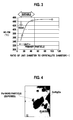
- FIG. 3 is a graph showing a relationship between D2/D1 as the ratio of D2 with respect to D1 and a temperature at which an HC conversion rate of the exhaust gas purifying catalyst reaches 50%.
- D2/D1 as the ratio of D2 with respect to D1 is within the range of: 1 ⁇ D2/D1 ⁇ 50, good exhaust gas purifying characteristics are obtained.
- FIG. 4 is a microscope picture after performing the exhaust durability testing at 900 °C for the exhaust gas purifying catalyst in which D2/D1 is within the range of: 1 ⁇ D2/D1 ⁇ 50.
- D2/D1 is within the range of: 1 ⁇ D2/D1 ⁇ 50
- the noble metal particles as the nanoparticles are supported on the surfaces of the first compounds, and are not embedded in the first compounds.
- a more preferable range of D2/D1 as the ratio of D2 with respect to D1 is 1 ⁇ D2/D1 ⁇ 20.
- D2/D1 is within the range of 1 ⁇ D2/D1 ⁇ 20, the above-described effect can be further exerted.
- the reason for the above are not necessarily obvious; however, the reason is considered to be because, within the range of: 1 ⁇ D2/D1 ⁇ 20, a decrease of such an exposed area of the noble metal particles 1, which is brought by being entangled into the secondary particles as the first compounds 2 in units partitioned by the second compounds 3, is less likely to occur, and a performance obtained by maintaining the state of the nanoparticles as the noble metal particles 1 can be further obtained. Also in the graph shown in FIG. 3 , the exhaust gas purifying characteristics are particularly excellent within the range of: 1 ⁇ D2/D1 ⁇ 20.
- a powder pore volume obtained by N 2 adsorption analysis for the powder of the exhaust gas purifying catalyst concerned be 0.3 [ml/g] to 0.5 [ml/g] per 1 g of the powder, and that an average pore diameter be 30 [nm] or less.
- the powder of the exhaust gas purifying catalyst according to the present invention has a pore structure that satisfies the above-described conditions, thus making it possible to allow the toxic exhaust gas to reach the catalyst active site (noble metal particles) kept as the microparticles in the first compound particles. Consequently, it becomes possible to fully extract the catalytic performance.
- the noble metal particles be contained totally by 8 ⁇ 10 -20 moles or less in the sections partitioned by the second compounds 3.
- the noble metal particles 1 are encapsulated in the second compounds 3 together with the first compounds.
- the plurality of noble metal particles 1 contained in the sections partitioned by the second compounds 3 sometimes move owing to the high temperature.
- the noble metal particles 1 do not move to the second compounds 3 owing to the effect of the first compounds 2 as the anchor members, move only in the sections (in the units) partitioned by the second compounds 3, and are coagulated into one or a plurality of the noble metal particles.
- FIG. 5 is a graph showing the diameter of the noble metal particle and a surface area of the noble metal with regard to platinum and palladium, which serve as the noble metals having the catalytic activity. Note that, in FIG. 5 , substantially the same curve is drawn both in the case where the noble metal is platinum and in the case where the noble metal is palladium, and accordingly, the relationship is drawn as one curve. As obvious from FIG.
- the particle diameter of the noble metal is 10 [nm] or less, the surface area of the particle is large, and sufficient activity is obtained. Accordingly, the deterioration of the catalytic activity, which may be caused by the coagulation, can be suppressed.
- FIG. 6 is a graph showing a relationship between the particle diameter of the noble metal and the number of atoms of the noble metal with regard to platinum and palladium, which serve as the noble metals having the catalytic activity. Note that, in FIG. 6 , substantially the same curve is drawn both in the case where the noble metal is platinum and in the case where the noble metal is palladium, and accordingly, the relationship is drawn as one curve. As obvious from FIG. 6 , the number of atoms when the particle diameter of the noble metal is 10 [nm] is approximately 48000. When this value is converted into the number of moles, the number of moles becomes approximately 8 ⁇ 10 -20 moles or less.
- the amount of noble metals in the units is restricted to be 8 ⁇ 10 -20 moles or less, thus making it possible to suppress the deterioration of the catalytic activity even if the noble metals are coagulated into one in each of the units.
- two means which are for reducing a support concentration of the noble metal particles 1 on the first compounds 2, and which are for reducing the particle diameter of the first compounds 2 which support the noble metal particles 1.
- the means is not limited to these.
- a volume of a honeycomb carrier on which the exhaust gas purifying catalyst is coated must be increased in order to maintain predetermined performance of the exhaust gas purifying catalyst.
- D2/D3 as a ratio of D2 with respect to D3 be 1 or more.
- D2/D3 stands for that the average particle diameter D2 of the units of the composite particles composed of the noble metal particles 1 and the first compounds 2 is larger than the average particle diameter D3 of gaps formed in the second compounds
- FIG. 7 is a graph showing relationships among D2/D3 as the ratio of the size D2 of the composite particles with respect to the average pore diameter D3, which is taken on an axis of abscissas, and a crystal growth rate of CeO 2 as the first compounds and a surface area of Pt as the noble metal particles after the exhaust durability testing, which are taken on axes of ordinates. From FIG.
- a method which includes the steps of: sintering first compounds in advance, and then supporting noble metal particles on the first compounds; milling the first compounds on which the noble metal particles are supported; and forming second compounds on the peripheries of the milled first compounds on which the noble metal particles are supported.
- the first compounds are composed of the composite containing the rare earth element and at least one of the alkali metal and the alkali earth metal.
- the first compounds as described above are sintered in advance, whereby the complexing of the rare earth element and the alkali metal or the alkali earth metal can be promoted, and the sintering caused therebetween can be suppressed.
- the noble metal particles are supported thereon, thus making it possible for the noble metal particles to maintain the state of the nanoparticles without being embedded in the first compounds.
- the first compounds on which the noble metal particles are supported are milled, thus making it possible to adjust the amount of noble metal in the sections (units) encapsulated by the second compounds within a predetermined range in the subsequent step.
- the second compounds are formed on the milled first compounds on which the noble metal particles are supported, whereby the first compounds on which the noble metal particles are supported are encapsulated by the second compounds, and are contained in the sections partitioned by the second compounds. Conditions when these steps are performed can be set appropriately. Moreover, steps other than these steps conform to the conventional method, and the exhaust gas purifying catalyst of the present invention can be manufactured.
- the powder of the exhaust gas purifying catalyst which is obtained as described above, is made into slurry, and this slurry is coated on inner wall surfaces of the catalyst honeycomb base member as a fire-resistant inorganic carrier. In such a way, the powder of the exhaust gas purifying catalyst serves for purifying the exhaust gas.
- Table 1 shows noble metal particles and first compounds in the exhaust gas purifying catalysts of Examples 1 to 27 and Comparative examples 1 to 5.
- Table 2 shows second compounds, catalyst powder characteristics and catalytic performances in the exhaust gas purifying catalysts of Examples 1 to 27 and Comparative examples 1 to 5.
- Example/Comparative example Species Support concentration to first compound (wt%) Rare earth element (%) Alkali/alkali earth elements Loading of alkali/alkali earth elements Addition of Zr Compound species Average secondary particle diameter; D2 (nm) Sintering temperate (°C*Hr) Crystallite diameter D1 (nm) Amount of noble metal in unit (mol/unit)
- Example 1 Pd 0.5 Ce Rb 5mol% None CeRbOx 310 600*3 9 5.4E-20
- Example 2 Pd 0.5 Ce Ba 5mol% None CeBaOx 310 600*3 9 5.4E-20
- Example 3 Pd 0.5 Ce Cs 5mol% None CeCsOx 310 600*3 9 5.4E-20
- Example 4 Pd 0.5 Ce Mg 5mol% None CeMgOx 330 600*3 9 6.5E-20
- Example 5 Pd 0.5 Nd Mg 5mol% None NdMgOx 290 600*3 10 4.4E-20
- Example 6 P
- a tetraamine Pd solution was supported so that the noble metal support concentration became 0.5 wt% to the powder, and was dried, followed by firing at 400°C for an hour in the air.
- the powder of Pd (0.5 wt%) /CeRbO x which was thus obtained, was milled in an aqueous solution, and dispersed slurry thereof with an average particle diameter of 310 nm was obtained.
- an average gap diameter thereof calculated by the N 2 adsorption method in the case of drying/firing only the boehmite under the same conditions was 22 nm.
- a pore diameter of the second compounds of the above-described noble metal-containing powder also conforms to the above-described value.
- a predetermined amount of the above-described powder and a predetermined amount of the boehmite were put into a magnetic pot, and were milled until an average particle diameter of a mixture thereof could reach 3 ⁇ m. Thereafter, a slurry of the milled mixture was coated on a cordierite-made honeycomb base member with a volume of 0.119 L (400 cpsi, 6 mil), and excessive slurry was removed therefrom in an airflow, followed by drying at 130 °C and firing at 400°C for an hour in the air atmosphere. In such a way, a catalyst honeycomb base member of Example 1 was obtained. An amount of the noble metal per 1 L of the catalyst honeycomb at this time was 0.5 g/L - honeycomb.
- a catalyst honeycomb of Example 2 was obtained in a similar way to Example 1 except that the Rb acetate in the above-described powder preparation step was changed to Ba acetate.
- a catalyst honeycomb of Example 3 was obtained in a similar way to Example 1 except that the Rb acetate in the above-described powder preparation step was changed to Cs acetate.
- a catalyst honeycomb of Example 4 was obtained in a similar way to Example 1 except that the Rb acetate in the above-described powder preparation step was changed to Mg acetate, and that an average particle diameter of dispersed slurry of Pd-supported CeMgO x powder in the same step was set at 330 nm.
- a catalyst honeycomb of Example 5 was obtained in a similar way to Example 1 except that the nanoparticle powder of the Ce oxide in the above-described powder preparation step was changed to Nd 2 O 3 , that the Rb acetate in the same step was changed to the Mg acetate, and that an average particle diameter of dispersed slurry of Pd-supported NdMgO x powder in the same step was set at 290 nm.
- a catalyst honeycomb of Example 6 was obtained in a similar way to Example 1 except that the nanoparticle powder of the Ce oxide in the above-described powder preparation step was changed to Pr 2 O 3 , that the Rb acetate in the same step was changed to Ca acetate, and that an average particle diameter of dispersed slurry of Pd-supported PrCaO x powder in the same step was set at 310 nm.
- La nitrate was impregnated into and supported on the nanoparticle powder of the Ce oxide in the above-described powder preparation step in Example 1 was impregnated so as to obtain CeO 2 on which 5 mol% of La was supported. Then, a mixture thus obtained was dried, and was fired at 400°C for an hour in an airflow. Subsequently, a predetermined amount of Mg acetate was impregnated into and supported on the mixture, and was then dried and fired, the noble metal was supported thereon, and a firing process similar way to Example 1 was performed therefor. Next, in the step of micro-graining powder, which was thus obtained, by milling, an average particle diameter was set at 310 nm. In a similar way to Example 1 except for the above, a catalyst honeycomb of Example 7 was obtained.
- a catalyst honeycomb of Example 8 was obtained in a similar way to Example 4 except that, in the above-described powder preparation step, the step of firing the raw material of the first compounds at 600°C for three hours was performed at 800°C for three hours.
- a catalyst honeycomb of Example 9 was obtained in a similar way to Example 4 except that, in the above-described powder preparation step, the step of firing the raw material of the first compounds at 600 °C for three hours was performed at 1000 °C for three hours, and that, in the step of milling the slurry, the average particle diameter thereof was set at 340 nm.
- a catalyst honeycomb of Example 10 was obtained in a similar way to Example 4 except that, in the above-described powder preparation step, the step of firing the raw material of the first compounds at 600°C for three hours was performed at 1100°C for three hours, and that, in the step of milling the slurry, the average particle diameter thereof was set at 350 nm.
- a catalyst honeycomb of Example 11 was obtained in a similar way to Example 9 except that, in the powder manufacturing step, the nanoparticle powder of the Ce oxide was changed to CeO 2 containing 10 mol% of Zr, and that, in the step of milling the slurry, the average particle diameter thereof was set at 330 nm.
- a catalyst honeycomb of Example 12 was obtained in a similar way to Example 11 except that the tetraamine Pd was changed to tetraamine Pt.
- a catalyst honeycomb of Example 13 was obtained in a similar way to Example 9 except that, in the above-described powder preparation step, the tetraamine Pd was changed to Rh nitrate, and that the average particle diameter of the milled slurry was set at 180 nm.
- a catalyst honeycomb of Example 14 was obtained in a similar way to Example 11 except that the support concentration of Pd to CeZrMgO x was set at 1.0%, that the average particle diameter of the slurry was set at 155 nm, that ⁇ -alumina was mixed thereinto so that the amount of noble metal per 1 L of the honeycomb became equivalent to Example 11 at the time of coating the slurry on the catalyst honeycomb.
- a catalyst honeycomb of Example 15 was obtained in a similar way to Example 4 except that CeMgO x was changed to CeNaO x .
- a catalyst honeycomb of Example 16 was obtained in a similar way to Example 4 except that CeMgO x was changed to CeKO x .
- a catalyst honeycomb of Example 17 was obtained in a similar way to Example 4 except that CeMgO x was changed to CeSrO x .
- a tetraamine Pd solution was supported so that the noble metal support concentration became 0.5 wt% to the powder, and was dried, followed by firing at 400°C for an hour in the air.
- the powder of Pd (0.5 wt%)/CeMgO x which was thus obtained, was milled in an aqueous solution, and dispersed slurry thereof with an average particle diameter of 330 nm was obtained.
- an average gap diameter thereof calculated by the N 2 adsorption method in the case of drying/firing only the boehmite under the same conditions was 22 nm.
- a pore diameter of the second compounds of the above-described noble metal-containing powder also conforms to the above-described value.
- a predetermined amount of the above-described powder and a predetermined amount of the boehmite were put into a magnetic pot, and were milled until an average particle diameter of a mixture thereof could reach 3 ⁇ m. Thereafter, a slurry of the milled mixture was coated on a cordierite-made honeycomb base member with a volume of 0.119 L (400 cpsi, 6 mil), and excessive slurry was removed therefrom in an airflow, followed by drying at 130°C and firing at 400°C for an hour in the air atmosphere. In such a way, a catalyst honeycomb base member of Example 18 was obtained. An amount of the noble metal per 1 L of the catalyst honeycomb at this time was 0.5 g/L - honeycomb.
- a dinitrodiamine Pd solution was supported so that the noble metal support concentration became 0.5 wt% to the powder, and was dried, followed by firing at 400°C for an hour in the air.
- the powder of Pd (0.5 wt%)/ZrCeO x which was thus obtained, was milled in an aqueous solution, and dispersed slurry thereof with an average particle diameter of 310 nm was obtained.
- an average gap diameter thereof calculated by the N 2 adsorption method in the case of drying/firing only the boehmite under the same conditions was 31 nm.
- a pore diameter of the second compounds of the above-described noble metal-containing powder also conforms to the above-described value.
- Example 19 a pore volume of Example 19, which was obtained at this time, was a value shown in Table 2.
- a predetermined amount of the above-described powder and a predetermined amount of the boehmite were put into a magnetic pot, and were milled until an average particle diameter of a mixture thereof could reach 3 ⁇ m. Thereafter, a slurry of the milled mixture was coated on a cordierite-made honeycomb base member with a volume of 0.119 L (400 cpsi, 6 mil), and excessive slurry was removed therefrom in an airflow, followed by drying at 130°C and firing at 400°C for an hour in the air atmosphere. In such a way, a catalyst honeycomb of Example 19 was obtained. An amount of the noble metal per 1 L of the catalyst honeycomb at this time was 0.5 g/L - honeycomb.
- a catalyst honeycomb of Example 20 was obtained in a similar way to Example 19 except that predetermined amounts of Ce nitrate and La nitrate were added to the Zr oxide so as to achieve a molar composition shown in Table 1 instead of adding Ce thereto, that Ce nitrate was put into the slurry in which the boehmite powder was dispersed, and that an average gap diameter of the boehmite for use was 28 nm.
- a catalyst honeycomb of Example 21 was obtained in a similar way to Example 19 except that predetermined amounts of Ce nitrate and Nd nitrate were added to the Zr oxide so as to achieve a molar composition shown in Table 1 instead of adding Ce thereto, that Ce nitrate, Zr nitrate and La nitrate were put into the slurry in which the boehmite powder was dispersed, and that an average gap diameter of the boehmite for use was 25 nm.
- a catalyst honeycomb of Example 22 was obtained in a similar way to Example 19 except that predetermined amounts of Ce nitrate and La nitrate were added to the Zr oxide so as to achieve a molar composition shown in Table 1 instead of adding Ce thereto, that Ce nitrate, Zr nitrate, La nitrate and Ba nitrate were put into the slurry in which the boehmite powder was dispersed, and that an average gap diameter of the boehmite for use was 25 nm.
- a catalyst honeycomb of Example 23 was obtained in a similar way to Example 19 except that predetermined amounts of Ce nitrate and Pr nitrate were added to the Zr oxide so as to achieve a molar composition shown in Table 1 instead of adding Ce thereto, that Ce nitrate, Zr nitrate, La nitrate and Ba nitrate were put into the slurry in which the boehmite powder was dispersed, and that an average gap diameter of the boehmite for use was 25 nm.
- a catalyst honeycomb of Example 24 was obtained in a similar way to Example 19 except that predetermined amounts of Ce nitrate and Pr nitrate were added to the Zr oxide so as to achieve a molar composition shown in Table 1 instead of adding Ce thereto, that Ce nitrate and Zr nitrate were put into the slurry in which the boehmite powder was dispersed, that an average gap diameter of the boehmite for use was 25 nm, and the dinitrodiamine Pd was changed to Rh nitrate.
- a catalyst honeycomb of Example 25 was obtained in a similar way to Example 4 except that predetermined amounts of Ce nitrate, Zr nitrate and La nitrate were put into the slurry in which the boehmite powder was dispersed so as to achieve a composition shown in Table 1, and that an average gap diameter of the boehmite for use was 24 nm.
- a catalyst honeycomb of Example 26 was obtained in a similar way to Example 19 except that predetermined amounts of Ce nitrate and Y nitrate were added to the Zr oxide so as to achieve a molar composition shown in Table 1 instead of adding Ce thereto.
- a catalyst honeycomb of Example 27 was obtained in a similar way to Example 24 except that predetermined amounts of Ce nitrate and Y nitrate were added to the Zr oxide so as to achieve a molar composition shown in Table 1 instead of adding Ce and Pr thereto.
- Comparative example 1 is an example where the first compounds in the catalyst powder contain only a rare earth element (Ce) as a main component.
- a dinitrodiamine Pd solution was supported so that a support concentration of the noble metal became 0.5 wt% to the powder, and was dried, followed by firing at 400°C for an hour in the air.
- the powder of Pd (0.5 wt%)/CeO 2 which was thus obtained, was milled in an aqueous solution, and dispersed slurry thereof with an average particle diameter of 310 nm was obtained.
- an average gap diameter thereof calculated by the N 2 adsorption method in the case of drying/firing only the boehmite under the same conditions was 22 nm.
- a pore diameter of the second compounds of the above-described noble metal-containing powder also conforms to the above-described value.
- a predetermined amount of the above-described powder and a predetermined amount of the boehmite were put into a magnetic pot, and were milled until an average particle diameter of a mixture thereof could reach 3 ⁇ m. Thereafter, a slurry of the milled mixture was coated on a cordierite-made honeycomb base member with a volume of 0.119 L (400 cpsi, 6 mil), and excessive slurry was removed therefrom in an airflow, followed by drying at 130°C and firing at 400°C for an hour in the air atmosphere. In such a way, a catalyst honeycomb base member of Comparative example 1 was obtained. An amount of the noble metal per 1 L of the catalyst honeycomb at this time was 0.5 g/L - honeycomb.
- Comparative example 2 is an example where the first compounds in the catalyst powder contain only rare earth elements (Ce-Zr (Ce-enriched)) as a main component.
- nanoparticle powder of Ce oxide containing 10 mol% of Zr a dinitrodiamine Pd solution was supported so that a support concentration of the noble metal became 1.0 wt% to the powder, and was dried, followed by firing at 400°C for three hours in the air.
- the powder of Pd (1.0 wt%)/CeZrO x which was thus obtained, was milled in an aqueous solution, and dispersed slurry thereof with an average particle diameter of 155 nm was obtained.
- an average gap diameter thereof calculated by the N 2 adsorption method in the case of drying/firing only the boehmite under the same conditions was 22 nm.
- a pore diameter of the second compounds of the above-described noble metal-containing powder also conforms to the above-described value.
- a predetermined amount of the above-described powder, ⁇ -alumina and a predetermined amount of the boehmite were put into a magnetic pot, and were milled until an average particle diameter of a mixture thereof could reach 3 ⁇ m. Thereafter, a slurry of the milled mixture was coated on a cordierite-made honeycomb base member with a volume of 0.119 L (400 cpsi, 6 mil), and excessive slurry was removed therefrom in an airflow, followed by drying at 130°C and firing at 400°C for an hour in the air atmosphere. In such a way, a catalyst honeycomb base member of Comparative example 2 was obtained. An amount of the noble metal per 1 L of the catalyst honeycomb at this time was 0.5 g/L - honeycomb.
- Comparative example 3 is an example where the first compounds in the catalyst powder contain only rare earth elements (Ce-Zr/alumina) as a main component, and the second compounds are not provided.
- Ce nitrate and zirconyl nitrate were impregnated so that Ce component became 10 mol% to the ⁇ -alumina and that Zr component became 3 mol%, and then was dried at 130°C, followed by firing at 400°C for three hours in the air.
- dinitrodiamine Pd was supported on the above-described powder so that a support concentration of Pd became 0.5 wt% to the powder, and was dried, followed by firing at 400°C for an hour.
- the above-described noble metal-supported powder, ⁇ -alumina, a predetermined amount of boehmite, and nitric acid were put into a magnetic pot, and were milled until an average particle diameter of a mixture thereof could reach 3 ⁇ m. Thereafter, a slurry of the milled mixture was coated on a cordierite-made honeycomb base member with a volume of 0.119 L (400 cpsi, 6 mil), and excessive slurry was removed therefrom in an airflow, followed by drying at 130°C and firing at 400°C for an hour in the air atmosphere. In such a way, a catalyst honeycomb base member of Comparative example 3 was obtained. An amount of the noble metal per 1 L of the catalyst honeycomb at this time was 0.5 g/L - honeycomb.
- a catalyst honeycomb base member of Comparative example 4 was obtained in a similar way to Comparative example 3 except that supported noble metal salt was changed to the dinitrodiamine Pt. An amount of the noble metal per 1 L of the catalyst honeycomb at this time was 0.5 g/L - honeycomb.
- Comparative example 5 is an example where the first compounds in the catalyst powder contain only rare Zr/alumina as a main component.
- zirconyl nitrate was impregnated so that Zr component became 3 mol% to the ⁇ -alumina, and then was dried at 130°C, followed by firing at 400°C. Subsequently, a Rh nitrate solution was supported on the obtained powder so that a support concentration of Rh became 0.5 wt% to the powder, and was dried, followed by firing at 400°C for an hour.
- the above-described noble metal-supported powder, ⁇ -alumina, a predetermined amount of boehmite, and nitric acid were put into a magnetic pot, and were milled until an average particle diameter of a mixture thereof could reach 3 ⁇ m. Thereafter, a slurry of the milled mixture was coated on a cordierite-made honeycomb base member with a volume of 0.119 L (400 cpsi, 6 mil), and excessive slurry was removed therefrom in an airflow, followed by drying at 130°C and firing at 400°C for an hour in the air atmosphere. In such a way, a catalyst honeycomb base member of Comparative example 5 was obtained. An amount of the noble metal per 1 L of the catalyst honeycomb at this time was 0.5 g/L - honeycomb.
- V6 engine display: 3.5 L (MPi)
- the respective catalyst honeycomb base members after being subjected to the above-described durability testing were built in a simulation exhaust gas flow apparatus, a simulation exhaust gas having a composition shown in the following Table 3 was flown through the respective catalyst honeycomb base members, and a temperature of each thereof was raised from 110 [°C] to 500 [°C] at a temperature rise rate of 10°C/min. Then, temperatures at which the HC conversion rate reaches 50% were obtained from HC concentrations on the inlet side and the outlet side, and were used as indices of the low-temperature activation.
- the catalyst powders were taken from the catalyst honeycomb base members, and were observed by a TEM.
- the used TEM is a field emission transmission electron microscope (HF-2000 made by Hitachi, Ltd.), and is attached with an EDX analyzer (SIGMA made by Kevex X-Ray Inc.) as an accessory.
- Example 1 to 27 the average particle diameters of the noble metals were kept small even after the durability testing, and therefore, the catalyst powders were excellent in the catalytic performance in terms of the low-temperature activation.
- Examples 1 to 17 and 19 to 25 in which D2/D1 as the ratio of D2 with respect to D1 was within the range of 1 ⁇ D2/D1 ⁇ 50 were superior to Example 18 in the catalytic performance in terms of the low-temperature activation.
- a microscope picture of the structure of Example 9 is as shown in FIG. 4 .
- Comparative examples 1 to 5 do not contain the alkali metal, the alkali earth metal, or the zirconia in the first compounds in the catalyst powders, or do not include the second compounds, and accordingly, Comparative examples 1 to 5 were inferior to Examples 1 to 25 in the effect of maintaining the nanometer diameter of the noble metal particles and the catalytic performance in terms of the low-temperature activation.
- the Pd catalyst powder of Example 19 the Rh catalyst powder of Example 24, boehmite and a nitric acid solution with a concentration of 10% were mixed, put into a magnetic pot, and milled until an average particle diameter of a mixture thereof could reach 3 [ ⁇ m]. Slurry thus obtained was coated on a cordierite-made honeycomb base member (0.92 L), and excessive slurry was removed therefrom in an airflow, followed by drying at 130°C and firing at 400°C for an hour in the air atmosphere. In such a way, a catalyst honeycomb of Example 28, which had the size suitable for the actual vehicle, was obtained. Amounts of Pd and Rh per 1 L of the catalyst honeycomb at this time were 0.8 g/L and 0.4 g/L, respectively.
- Example 29 A catalyst honeycomb of Example 29, which had the size suitable for the actual vehicle, was obtained in a similar way to Example 28 except that the Pd powder used in Example 26 was used instead of the Pd powder of Example 28, and that the Rh powder used in Example 27 was used as Rh powder.
- Amounts of the noble metals on the catalyst honeycomb at this time were similar to those of Example 28.
- Amounts of the noble metals on the catalyst honeycomb at this time were similar to those of Example 28.
- Example 28 The respective catalyst honeycomb base members of Example 28, Example 29 and Comparative example 6, which had the size suitable for the actual vehicle, were mounted on an exhaust system of an engine of a vehicle, and emission analysis of the exhaust gas was conducted therefor.
- the vehicle for use in this vehicle evaluation testing was made by Nissan Motor Co., Ltd., and the engine mounted thereon was QE25DE with a displacement of 2.5 [L].
- a volume of the honeycomb base member was 0.92 [L].
- An evaluation mode was the LA4-cold start mode.
- the durability testing was conducted for the respective catalyst honeycomb base members of Example 28, Example 29 and Comparative example 6, which had the size suitable for the actual vehicle and were used for the above-described vehicle evaluation testing.
- OSC amounts of the respective catalyst honeycomb base members before and after the durability testing were individually measured, and the amounts of the oxygen storage capacities of the catalysts after the durability testing were compared with the initial oxygen storage capacities thereof taken as 1.0. In such a way, the durability on OSC of each of the catalysts was evaluated.
- the catalyst honeycomb base members before and after the durability testing were partially taken out, the taken catalysts were milled together with the cordierite base members, and the powders before the durability testing and the powders after the durability testing were individually prepared.
- the respective powders were fired once at 600 [°C] for three hours in an airflow, and organic substances adhered onto the catalysts were removed. Thereafter, a temperature of each catalyst was raised to 600°C at a rate of 10°C/min in a flow of Hr, and treatment for eliminating oxygen in each catalyst was performed. Thereafter, the respective catalysts were stabilized at 500 [°C], a fixed amount of oxygen was then introduced thereonto at a pulse, and the measurement of the oxygen storage capacities was conducted by a thermal conductivity detector (TCD). Ratios of the initial oxygen storage amounts Qf by the powders before the durability testing and the post-durability oxygen storage amounts Qa by the powders after the durability testing were taken, and the durability of each of the catalysts was confirmed.
- TCD thermal conductivity detector
Applications Claiming Priority (4)
| Application Number | Priority Date | Filing Date | Title |
|---|---|---|---|
| JP2007015158 | 2007-01-25 | ||
| JP2007112313 | 2007-04-20 | ||
| JP2007237100A JP4971918B2 (ja) | 2007-01-25 | 2007-09-12 | 排気ガス浄化用触媒及びその製造方法 |
| EP08001250A EP1952876A1 (de) | 2007-01-25 | 2008-01-23 | Abgasreinigungskatalysator und zugehöriges Herstellungsverfahren |
Related Parent Applications (1)
| Application Number | Title | Priority Date | Filing Date |
|---|---|---|---|
| EP08001250A Division EP1952876A1 (de) | 2007-01-25 | 2008-01-23 | Abgasreinigungskatalysator und zugehöriges Herstellungsverfahren |
Publications (2)
| Publication Number | Publication Date |
|---|---|
| EP2055367A2 true EP2055367A2 (de) | 2009-05-06 |
| EP2055367A3 EP2055367A3 (de) | 2009-05-27 |
Family
ID=39473995
Family Applications (2)
| Application Number | Title | Priority Date | Filing Date |
|---|---|---|---|
| EP20090001627 Ceased EP2055367A3 (de) | 2007-01-25 | 2008-01-23 | Abgasreinigungskatalysator und zugehöriges Herstellungsverfahren |
| EP08001250A Ceased EP1952876A1 (de) | 2007-01-25 | 2008-01-23 | Abgasreinigungskatalysator und zugehöriges Herstellungsverfahren |
Family Applications After (1)
| Application Number | Title | Priority Date | Filing Date |
|---|---|---|---|
| EP08001250A Ceased EP1952876A1 (de) | 2007-01-25 | 2008-01-23 | Abgasreinigungskatalysator und zugehöriges Herstellungsverfahren |
Country Status (3)
| Country | Link |
|---|---|
| US (1) | US7851405B2 (de) |
| EP (2) | EP2055367A3 (de) |
| KR (1) | KR100989224B1 (de) |
Families Citing this family (40)
| Publication number | Priority date | Publication date | Assignee | Title |
|---|---|---|---|---|
| US20050195966A1 (en) * | 2004-03-03 | 2005-09-08 | Sigma Dynamics, Inc. | Method and apparatus for optimizing the results produced by a prediction model |
| US8470495B2 (en) * | 2005-07-19 | 2013-06-25 | Lg Chem, Ltd. | Electrode catalyst with improved longevity properties and fuel cell using the same |
| EP2055367A3 (de) * | 2007-01-25 | 2009-05-27 | Nissan Motor Co., Ltd. | Abgasreinigungskatalysator und zugehöriges Herstellungsverfahren |
| US7977276B2 (en) * | 2007-04-12 | 2011-07-12 | Nissan Motor Co., Ltd. | Exhaust gas purifying catalyst and method of producing the same |
| US9173967B1 (en) | 2007-05-11 | 2015-11-03 | SDCmaterials, Inc. | System for and method of processing soft tissue and skin with fluids using temperature and pressure changes |
| US8507401B1 (en) | 2007-10-15 | 2013-08-13 | SDCmaterials, Inc. | Method and system for forming plug and play metal catalysts |
| FR2922784B1 (fr) * | 2007-10-29 | 2011-05-13 | Inst Francais Du Petrole | Catalyseur comprenant du palladium et son application en hydrogenation selective |
| JP5273446B2 (ja) * | 2008-05-12 | 2013-08-28 | 日産自動車株式会社 | 排ガス浄化用触媒及びその製造方法 |
| JP5348135B2 (ja) * | 2008-07-04 | 2013-11-20 | 日産自動車株式会社 | 排気ガス浄化用触媒 |
| JP5526502B2 (ja) * | 2008-07-16 | 2014-06-18 | 日産自動車株式会社 | 排気ガス浄化用触媒及びその製造方法 |
| JP5447377B2 (ja) | 2008-07-31 | 2014-03-19 | 日産自動車株式会社 | 排気ガス浄化触媒 |
| WO2010071205A1 (ja) * | 2008-12-19 | 2010-06-24 | 株式会社 キャタラー | 排ガス浄化用触媒 |
| RU2477176C1 (ru) | 2009-03-04 | 2013-03-10 | Ниссан Мотор Ко., Лтд. | Катализатор нейтрализации отработанных газов и способ его получения |
| JP5515936B2 (ja) | 2009-08-18 | 2014-06-11 | マツダ株式会社 | 排気ガス浄化用触媒 |
| JP5041103B2 (ja) | 2009-11-17 | 2012-10-03 | 日産自動車株式会社 | 排ガス浄化用触媒及びその製造方法 |
| US8545652B1 (en) | 2009-12-15 | 2013-10-01 | SDCmaterials, Inc. | Impact resistant material |
| US9149797B2 (en) | 2009-12-15 | 2015-10-06 | SDCmaterials, Inc. | Catalyst production method and system |
| US8470112B1 (en) | 2009-12-15 | 2013-06-25 | SDCmaterials, Inc. | Workflow for novel composite materials |
| US9090475B1 (en) | 2009-12-15 | 2015-07-28 | SDCmaterials, Inc. | In situ oxide removal, dispersal and drying for silicon SiO2 |
| US8803025B2 (en) | 2009-12-15 | 2014-08-12 | SDCmaterials, Inc. | Non-plugging D.C. plasma gun |
| US9126191B2 (en) | 2009-12-15 | 2015-09-08 | SDCmaterials, Inc. | Advanced catalysts for automotive applications |
| US8557727B2 (en) | 2009-12-15 | 2013-10-15 | SDCmaterials, Inc. | Method of forming a catalyst with inhibited mobility of nano-active material |
| US8652992B2 (en) | 2009-12-15 | 2014-02-18 | SDCmaterials, Inc. | Pinning and affixing nano-active material |
| WO2011108250A1 (ja) | 2010-03-02 | 2011-09-09 | 日本板硝子株式会社 | 貴金属微粒子担持触媒およびその製造方法、ならびに浄化触媒 |
| US8580701B2 (en) * | 2010-11-19 | 2013-11-12 | Corning Incorporated | Method of controlling Ce:Zr ratio in oxide nanoparticles |
| US8669202B2 (en) | 2011-02-23 | 2014-03-11 | SDCmaterials, Inc. | Wet chemical and plasma methods of forming stable PtPd catalysts |
| MX2014001718A (es) | 2011-08-19 | 2014-03-26 | Sdcmaterials Inc | Sustratos recubiertos para uso en catalisis y convertidores cataliticos y metodos para recubrir sustratos con composiciones de recubrimiento delgado. |
| JP5831083B2 (ja) | 2011-09-20 | 2015-12-09 | 日産自動車株式会社 | 排ガス浄化用触媒及びその製造方法 |
| JP5992192B2 (ja) * | 2012-03-30 | 2016-09-14 | 三井金属鉱業株式会社 | パラジウム触媒 |
| US9511352B2 (en) | 2012-11-21 | 2016-12-06 | SDCmaterials, Inc. | Three-way catalytic converter using nanoparticles |
| US9156025B2 (en) | 2012-11-21 | 2015-10-13 | SDCmaterials, Inc. | Three-way catalytic converter using nanoparticles |
| EP2954950B1 (de) * | 2013-02-08 | 2020-06-17 | Umicore Shokubai Japan Co., Ltd. | Katalysator zur abgasreinigung mit nox-okklusionsminimierung und abgasreinigungsverfahren unter verwendung dieses katalysators |
| WO2015013545A1 (en) | 2013-07-25 | 2015-01-29 | SDCmaterials, Inc. | Washcoats and coated substrates for catalytic converters |
| KR20160074566A (ko) | 2013-10-22 | 2016-06-28 | 에스디씨머티리얼스, 인코포레이티드 | 대형 디젤 연소 엔진용 촉매 디자인 |
| JP2016535664A (ja) | 2013-10-22 | 2016-11-17 | エスディーシーマテリアルズ, インコーポレイテッド | リーンNOxトラップの組成物 |
| US9415378B2 (en) | 2013-12-02 | 2016-08-16 | Saudi Basic Industries Corporation | Dehydrogenation catalyst, its use and method of preparation |
| US9687811B2 (en) | 2014-03-21 | 2017-06-27 | SDCmaterials, Inc. | Compositions for passive NOx adsorption (PNA) systems and methods of making and using same |
| WO2017002357A1 (en) | 2015-06-29 | 2017-01-05 | Okinawa Institute Of Science And Technology School Corporation | Engineering high-performance palladium core magnesium oxide porous shell nanocatalysts via heterogeneous gas-phase synthesis |
| KR102246434B1 (ko) | 2017-07-19 | 2021-04-29 | (주)엘지하우시스 | 자동차 배기가스 처리용 촉매입자, 이의 제조방법 및 이를 이용하여 자동차 배기가스를 처리하는 방법 |
| KR102365461B1 (ko) * | 2017-09-29 | 2022-02-21 | (주)엘엑스하우시스 | 배기가스 처리용 촉매입자, 이의 제조방법 및 이를 이용하여 자동차 배기가스를 처리하는 방법 |
Citations (3)
| Publication number | Priority date | Publication date | Assignee | Title |
|---|---|---|---|---|
| US6335305B1 (en) | 1999-01-18 | 2002-01-01 | Kabushiki Kaisha Toyota Chuo Kenkyusho | Catalyst for purifying exhaust gas |
| WO2007145350A1 (en) | 2006-06-13 | 2007-12-21 | Kabushiki Kaisha Toyota Chuo Kenkyusho | Catalyst for purification of exhaust gas |
| EP2098292A1 (de) * | 2006-11-14 | 2009-09-09 | Nissan Motor Co., Ltd. | Abgasreinigungskatalysator |
Family Cites Families (16)
| Publication number | Priority date | Publication date | Assignee | Title |
|---|---|---|---|---|
| JPH08131830A (ja) | 1994-11-07 | 1996-05-28 | Toyota Motor Corp | 排ガス浄化用触媒 |
| US6492297B1 (en) * | 2000-09-15 | 2002-12-10 | Engelhard Corporation | Catalyst composition for purifying exhaust gas |
| US6866834B2 (en) * | 2001-03-12 | 2005-03-15 | Nissan Motor Co., Ltd. | NOx reduction catalyst and NOx reduction system |
| JP3861647B2 (ja) | 2001-10-09 | 2006-12-20 | トヨタ自動車株式会社 | 排ガス浄化用触媒 |
| JP4175186B2 (ja) | 2003-06-12 | 2008-11-05 | トヨタ自動車株式会社 | 排ガス浄化用触媒とその製造方法 |
| JP4196745B2 (ja) | 2003-06-12 | 2008-12-17 | トヨタ自動車株式会社 | 排ガス浄化用触媒 |
| JP4959129B2 (ja) * | 2004-02-16 | 2012-06-20 | 株式会社キャタラー | 排ガス浄化用触媒 |
| JP2005329318A (ja) * | 2004-05-19 | 2005-12-02 | Mazda Motor Corp | ディーゼルパティキュレートフィルタ |
| JP2006068665A (ja) * | 2004-09-03 | 2006-03-16 | Toyota Motor Corp | 排ガス浄化触媒の製造方法及び排ガス浄化触媒 |
| JP2007015158A (ja) | 2005-07-06 | 2007-01-25 | Brother Ind Ltd | 記録装置および記録装置制御プログラム |
| JP2007112313A (ja) | 2005-10-20 | 2007-05-10 | Bridgestone Corp | 空気入りタイヤ |
| JP4413879B2 (ja) | 2006-03-09 | 2010-02-10 | 独立行政法人国立高等専門学校機構 | 水質浄化材および人工藻並びにそれらの製造方法 |
| JP4826337B2 (ja) * | 2006-05-23 | 2011-11-30 | マツダ株式会社 | 排気ガス浄化用触媒及び排気ガス浄化方法 |
| JP4853291B2 (ja) * | 2007-01-10 | 2012-01-11 | 日産自動車株式会社 | 排気ガス浄化触媒及びその製造方法 |
| EP2055367A3 (de) * | 2007-01-25 | 2009-05-27 | Nissan Motor Co., Ltd. | Abgasreinigungskatalysator und zugehöriges Herstellungsverfahren |
| US7977276B2 (en) * | 2007-04-12 | 2011-07-12 | Nissan Motor Co., Ltd. | Exhaust gas purifying catalyst and method of producing the same |
-
2008
- 2008-01-23 EP EP20090001627 patent/EP2055367A3/de not_active Ceased
- 2008-01-23 EP EP08001250A patent/EP1952876A1/de not_active Ceased
- 2008-01-25 KR KR1020080008004A patent/KR100989224B1/ko active IP Right Grant
- 2008-01-25 US US12/010,514 patent/US7851405B2/en active Active
Patent Citations (3)
| Publication number | Priority date | Publication date | Assignee | Title |
|---|---|---|---|---|
| US6335305B1 (en) | 1999-01-18 | 2002-01-01 | Kabushiki Kaisha Toyota Chuo Kenkyusho | Catalyst for purifying exhaust gas |
| WO2007145350A1 (en) | 2006-06-13 | 2007-12-21 | Kabushiki Kaisha Toyota Chuo Kenkyusho | Catalyst for purification of exhaust gas |
| EP2098292A1 (de) * | 2006-11-14 | 2009-09-09 | Nissan Motor Co., Ltd. | Abgasreinigungskatalysator |
Also Published As
| Publication number | Publication date |
|---|---|
| KR100989224B1 (ko) | 2010-10-20 |
| US7851405B2 (en) | 2010-12-14 |
| EP2055367A3 (de) | 2009-05-27 |
| KR20080070587A (ko) | 2008-07-30 |
| US20080187714A1 (en) | 2008-08-07 |
| EP1952876A1 (de) | 2008-08-06 |
Similar Documents
| Publication | Publication Date | Title |
|---|---|---|
| US7851405B2 (en) | Exhaust gas purifying catalyst and manufacturing method thereof | |
| JP5458126B2 (ja) | 排気ガス浄化用触媒及びその製造方法 | |
| ES2458499T5 (es) | Método para preparación de un material de almacenamiento de NOx | |
| CA2562556C (en) | Process for producing metal oxide particle and exhaust gas purifying catalyst | |
| EP1740307B1 (de) | Metalloxidteilchen, herstellungsverfahren dafür und abgasreinigungskatalysator | |
| JP5661989B2 (ja) | 高耐熱性触媒及びその製造方法 | |
| US20070197373A1 (en) | Zirconia core particles coated with ceria particles, production process thereof and exhaust gas purifying catalyst | |
| EP1771383A2 (de) | Mit certeilchen beschichtete zirconiumoxidkernteilchen, herstellungsverfahren dafür und abgasreinigungskatalysator | |
| US8999886B2 (en) | Catalyst support particle, production process thereof and exhaust gas purifying catalyst | |
| JP2011147901A (ja) | 排ガス浄化用触媒 | |
| EP3466535A1 (de) | Dreiwegkatalysator zur benzinmotorabgasreinigung | |
| EP2311559A1 (de) | Abgasreinigungskatalysator und verfahren zu seiner herstellung | |
| JP4831753B2 (ja) | 排ガス浄化用触媒 | |
| US11484864B2 (en) | Exhaust gas-purifying three-way catalyst and method for producing same, and integral structure type exhaust gas-purifying catalyst | |
| JP2008272745A (ja) | 排ガス浄化用触媒 | |
| JP4306625B2 (ja) | 自動車の排ガス浄化用触媒体およびその製造方法 | |
| JP2005279437A (ja) | 排ガス浄化用触媒 | |
| JP3362532B2 (ja) | 排ガス浄化用触媒及びその製造方法 | |
| JP2006320863A (ja) | 排ガス浄化触媒及びその製造方法 | |
| US20230294078A1 (en) | Exhaust gas purification catalyst | |
| JP4805031B2 (ja) | 排ガス浄化触媒、その製造方法及び使用方法 | |
| JP2007167707A (ja) | 排ガス浄化用触媒とその製造方法 |
Legal Events
| Date | Code | Title | Description |
|---|---|---|---|
| PUAI | Public reference made under article 153(3) epc to a published international application that has entered the european phase |
Free format text: ORIGINAL CODE: 0009012 |
|
| PUAL | Search report despatched |
Free format text: ORIGINAL CODE: 0009013 |
|
| 17P | Request for examination filed |
Effective date: 20090205 |
|
| AC | Divisional application: reference to earlier application |
Ref document number: 1952876 Country of ref document: EP Kind code of ref document: P |
|
| AK | Designated contracting states |
Kind code of ref document: A2 Designated state(s): AT BE BG CH CY CZ DE DK EE ES FI FR GB GR HR HU IE IS IT LI LT LU LV MC MT NL NO PL PT RO SE SI SK TR |
|
| AX | Request for extension of the european patent |
Extension state: AL BA MK RS |
|
| AK | Designated contracting states |
Kind code of ref document: A3 Designated state(s): AT BE BG CH CY CZ DE DK EE ES FI FR GB GR HR HU IE IS IT LI LT LU LV MC MT NL NO PL PT RO SE SI SK TR |
|
| AX | Request for extension of the european patent |
Extension state: AL BA MK RS |
|
| AKX | Designation fees paid |
Designated state(s): DE FR GB |
|
| 17Q | First examination report despatched |
Effective date: 20120419 |
|
| STAA | Information on the status of an ep patent application or granted ep patent |
Free format text: STATUS: THE APPLICATION HAS BEEN REFUSED |
|
| 18R | Application refused |
Effective date: 20150303 |