EP2053845B1 - Mitgeführte Bildverarbeitungsvorrichtung und Steuerungsverfahren für die mitgeführte Bildverarbeitungsvorrichtung - Google Patents
Mitgeführte Bildverarbeitungsvorrichtung und Steuerungsverfahren für die mitgeführte Bildverarbeitungsvorrichtung Download PDFInfo
- Publication number
- EP2053845B1 EP2053845B1 EP07831568A EP07831568A EP2053845B1 EP 2053845 B1 EP2053845 B1 EP 2053845B1 EP 07831568 A EP07831568 A EP 07831568A EP 07831568 A EP07831568 A EP 07831568A EP 2053845 B1 EP2053845 B1 EP 2053845B1
- Authority
- EP
- European Patent Office
- Prior art keywords
- photographing
- unit
- brightness
- image
- subject
- Prior art date
- Legal status (The legal status is an assumption and is not a legal conclusion. Google has not performed a legal analysis and makes no representation as to the accuracy of the status listed.)
- Not-in-force
Links
Images


Classifications
-
- B—PERFORMING OPERATIONS; TRANSPORTING
- B60—VEHICLES IN GENERAL
- B60R—VEHICLES, VEHICLE FITTINGS, OR VEHICLE PARTS, NOT OTHERWISE PROVIDED FOR
- B60R11/00—Arrangements for holding or mounting articles, not otherwise provided for
- B60R11/04—Mounting of cameras operative during drive; Arrangement of controls thereof relative to the vehicle
-
- G—PHYSICS
- G03—PHOTOGRAPHY; CINEMATOGRAPHY; ANALOGOUS TECHNIQUES USING WAVES OTHER THAN OPTICAL WAVES; ELECTROGRAPHY; HOLOGRAPHY
- G03B—APPARATUS OR ARRANGEMENTS FOR TAKING PHOTOGRAPHS OR FOR PROJECTING OR VIEWING THEM; APPARATUS OR ARRANGEMENTS EMPLOYING ANALOGOUS TECHNIQUES USING WAVES OTHER THAN OPTICAL WAVES; ACCESSORIES THEREFOR
- G03B15/00—Special procedures for taking photographs; Apparatus therefor
- G03B15/02—Illuminating scene
- G03B15/03—Combinations of cameras with lighting apparatus; Flash units
- G03B15/05—Combinations of cameras with electronic flash apparatus; Electronic flash units
-
- G—PHYSICS
- G06—COMPUTING OR CALCULATING; COUNTING
- G06T—IMAGE DATA PROCESSING OR GENERATION, IN GENERAL
- G06T5/00—Image enhancement or restoration
- G06T5/50—Image enhancement or restoration using two or more images, e.g. averaging or subtraction
-
- G—PHYSICS
- G06—COMPUTING OR CALCULATING; COUNTING
- G06V—IMAGE OR VIDEO RECOGNITION OR UNDERSTANDING
- G06V10/00—Arrangements for image or video recognition or understanding
- G06V10/10—Image acquisition
- G06V10/12—Details of acquisition arrangements; Constructional details thereof
- G06V10/14—Optical characteristics of the device performing the acquisition or on the illumination arrangements
- G06V10/141—Control of illumination
-
- G—PHYSICS
- G06—COMPUTING OR CALCULATING; COUNTING
- G06V—IMAGE OR VIDEO RECOGNITION OR UNDERSTANDING
- G06V40/00—Recognition of biometric, human-related or animal-related patterns in image or video data
- G06V40/10—Human or animal bodies, e.g. vehicle occupants or pedestrians; Body parts, e.g. hands
- G06V40/18—Eye characteristics, e.g. of the iris
- G06V40/19—Sensors therefor
-
- H—ELECTRICITY
- H04—ELECTRIC COMMUNICATION TECHNIQUE
- H04N—PICTORIAL COMMUNICATION, e.g. TELEVISION
- H04N23/00—Cameras or camera modules comprising electronic image sensors; Control thereof
- H04N23/56—Cameras or camera modules comprising electronic image sensors; Control thereof provided with illuminating means
-
- H—ELECTRICITY
- H04—ELECTRIC COMMUNICATION TECHNIQUE
- H04N—PICTORIAL COMMUNICATION, e.g. TELEVISION
- H04N23/00—Cameras or camera modules comprising electronic image sensors; Control thereof
- H04N23/60—Control of cameras or camera modules
-
- H—ELECTRICITY
- H04—ELECTRIC COMMUNICATION TECHNIQUE
- H04N—PICTORIAL COMMUNICATION, e.g. TELEVISION
- H04N23/00—Cameras or camera modules comprising electronic image sensors; Control thereof
- H04N23/70—Circuitry for compensating brightness variation in the scene
- H04N23/73—Circuitry for compensating brightness variation in the scene by influencing the exposure time
-
- H—ELECTRICITY
- H04—ELECTRIC COMMUNICATION TECHNIQUE
- H04N—PICTORIAL COMMUNICATION, e.g. TELEVISION
- H04N23/00—Cameras or camera modules comprising electronic image sensors; Control thereof
- H04N23/95—Computational photography systems, e.g. light-field imaging systems
- H04N23/951—Computational photography systems, e.g. light-field imaging systems by using two or more images to influence resolution, frame rate or aspect ratio
-
- G—PHYSICS
- G03—PHOTOGRAPHY; CINEMATOGRAPHY; ANALOGOUS TECHNIQUES USING WAVES OTHER THAN OPTICAL WAVES; ELECTROGRAPHY; HOLOGRAPHY
- G03B—APPARATUS OR ARRANGEMENTS FOR TAKING PHOTOGRAPHS OR FOR PROJECTING OR VIEWING THEM; APPARATUS OR ARRANGEMENTS EMPLOYING ANALOGOUS TECHNIQUES USING WAVES OTHER THAN OPTICAL WAVES; ACCESSORIES THEREFOR
- G03B2215/00—Special procedures for taking photographs; Apparatus therefor
- G03B2215/05—Combinations of cameras with electronic flash units
- G03B2215/0514—Separate unit
- G03B2215/0517—Housing
- G03B2215/0553—Housing with second integrated flash
-
- G—PHYSICS
- G03—PHOTOGRAPHY; CINEMATOGRAPHY; ANALOGOUS TECHNIQUES USING WAVES OTHER THAN OPTICAL WAVES; ELECTROGRAPHY; HOLOGRAPHY
- G03B—APPARATUS OR ARRANGEMENTS FOR TAKING PHOTOGRAPHS OR FOR PROJECTING OR VIEWING THEM; APPARATUS OR ARRANGEMENTS EMPLOYING ANALOGOUS TECHNIQUES USING WAVES OTHER THAN OPTICAL WAVES; ACCESSORIES THEREFOR
- G03B2215/00—Special procedures for taking photographs; Apparatus therefor
- G03B2215/05—Combinations of cameras with electronic flash units
- G03B2215/0564—Combinations of cameras with electronic flash units characterised by the type of light source
- G03B2215/0567—Solid-state light source, e.g. LED, laser
-
- G—PHYSICS
- G06—COMPUTING OR CALCULATING; COUNTING
- G06T—IMAGE DATA PROCESSING OR GENERATION, IN GENERAL
- G06T2207/00—Indexing scheme for image analysis or image enhancement
- G06T2207/10—Image acquisition modality
- G06T2207/10141—Special mode during image acquisition
- G06T2207/10152—Varying illumination
-
- G—PHYSICS
- G06—COMPUTING OR CALCULATING; COUNTING
- G06T—IMAGE DATA PROCESSING OR GENERATION, IN GENERAL
- G06T2207/00—Indexing scheme for image analysis or image enhancement
- G06T2207/30—Subject of image; Context of image processing
- G06T2207/30196—Human being; Person
- G06T2207/30201—Face
-
- G—PHYSICS
- G08—SIGNALLING
- G08G—TRAFFIC CONTROL SYSTEMS
- G08G1/00—Traffic control systems for road vehicles
- G08G1/16—Anti-collision systems
Definitions
- the present invention relates to a vehicle-mounted image processing device and a method for controlling a vehicle-mounted image processing device that photographs facial images of a vehicle driver.
- Patent Document 1 Unexamined Japanese Patent Application KOKAI Publication No. 2002-352229
- Patent Document 2 Unexamined Japanese Patent Application KOKAI Publication No. 2004-070512
- the US 2004/005083 A1 discloses a system and methods for non-intrusive real-time eye detection and tracking.
- a subject's eyes can be detected by using active illumination analysis to generate a difference image of the subject.
- the difference image the bright pupil effect intensifies the appearance of the subject's pupils.
- a component analysis can be used to identify a set of pupil candidates from the difference image.
- An appearance-based analysis can be applied to the pupil candidates to identify the subject's eyes from background noise that can occur under various lighting conditions.
- US 2004/0170304 A1 discloses a similar system in which the exposure times are to be balanced based on certain portions within the images.
- Patent Document 1 discloses a detection device that determines light reflected by glasses etc. picked up in a facial image of a driver illuminated from different directions and removes the picked up reflected light from the facial image. This detection device discerns differences between relative positions of a bright region positioned in the vicinity of the eyes on a facial image of the driver illuminated from a prescribed direction and a bright region positioned in the vicinity of the eyes on the facial image of the driver illuminated from a different direction to the first direction as light reflected due to glasses etc.
- Patent Document 2 discloses a facial state detection device that determines a direction toward which a driver is facing based on the facial image of the driver. This facial state detection device takes facial images consecutively at prescribed intervals. The facial state detection device then obtains the difference between the brightness of each pixel for the facial image photographed on this occasion and the brightness of each pixel for the corresponding facial image taken on the previous occasion. The direction toward which the face of the driver is facing is then discerned based on a change in barycentric coordinates of a region consists of pixels of which this difference is a prescribed value or more.
- a vehicle-mounted image processing device of a first aspect of the present invention is provided as defined in claim 1.
- a vehicle-mounted camera system (including a vehicle-mounted image processing device, and a method for controlling a vehicle-mounted image processing device) of the first embodiment includes a vehicle-mounted camera 1 and an ECU (Engine Control Unit) 2.
- ECU Engine Control Unit
- the ECU 2 is an electronic control device that controls the operation of the entire vehicle.
- the ECU 2 receives facial images that are images showing the face of the driver from the vehicle-mounted camera 1 and detects inattentive driving by the driver based on the facial images.
- the vehicle-mounted camera 1 includes a camera 10, an optical filter 11, a first LED (Light-Emitting Diode) illuminating device 12, and a second LED illuminating device 13.
- the optical filter 11 is an optical band-pass filter that is provided at the front surface of the camera 10 as shown in FIG. 2 .
- the optical filter 11 is constructed from an optical filter with a large transmittance (%) with respect to light (for example, near infrared light) having a prescribed wavelength as shown in FIG. 3 . This reduces the amount of light reflected by glasses etc. worn by the driver incident to the camera 10.
- the first LED illuminating device 12 and the second LED illuminating device 13 respectively have a plurality of LEDs for illuminating the face of the driver.
- the first LED illuminating device 12 is disposed to the left side of the camera 10 when viewed from the front of the vehicle-mounted camera 1.
- the second LED illuminating device 13 is disposed to the right side of the camera 10.
- the LEDs of each of the illuminating devices 12 and 13 it is preferable for the LEDs of each of the illuminating devices 12 and 13 to have characteristic which the wavelength region for which the light intensity ( ⁇ W) when light is generated is a maximum to substantially coincide with the wavelength region for which the transmittance (%) of the optical filter 11 is a maximum.
- the camera 10 includes a DSP (Digital Signal Processor) 100, an LED control circuit 110, a first LED drive circuit 120, a second LED drive circuit 130, a photographing unit 140, a V-driver 150, an EEPROM 160, and a driver 170.
- DSP Digital Signal Processor
- the LED control circuit 110 controls the illumination of each of the illuminating devices 12 and 13 in accordance with the illumination timing for the first LED illuminating device 12 and the second LED illuminating device 13 notified by the DSP 100. In order to implement this control, the LED control circuit 110 sends a lighting signal instructing the illumination of each of the illuminating devices 12 and 13 to the first LED drive circuit 120 and the second LED drive circuit 130.
- the first LED drive circuit 120 and the second LED drive circuit 130 then supply LED drive current to the first LED illuminating device 12 and the second LED illuminating device 13 so as to light the LEDs of each of the illuminating devices 12 and 13 in response to the lighting signal sent from the LED control circuit 110.
- the photographing unit 140 includes CCD (Charge-Coupled Devices), takes facial images of the driver, and sends the facial images to the DSP 100.
- the transmission method is a non-interlaced method with 30 pictures being taken per second (i.e. a frame period in which the photographing unit 140 takes a picture of one frame is 1/30 seconds).
- the resolution of the facial image after A/D (Analog to Digital) conversion by the DSP 100 is taken to be 240 vertical pixels by 320 horizontal pixels.
- the V (Video) -driver 150 is a control interface that controls the operation of the photographing unit 140 in accordance with an exposure time for the photographing unit 140 and photographing timing for the facial images notified by the DSP 100.
- the EEPROM 160 stores a control program etc. for the camera 10 and functions as a work area for the DSP 100.
- the driver 170 is a communication interface for performing communication with the ECU 2.
- the driver 170 receives facial images after image processing by the DSP 100 from the DSP 100 and sends the facial images to the ECU 2.
- the DSP 100 is a processing device that mainly subject images acquired by the photographing unit 140 to prescribed image processing.
- the DSP 100 includes a CPU 101, a TG (Timing Generator)/SSG (Sync Signal Generator) 102, an ADC (Analog/Digital Converter) 103, a signal processing unit 104, and a DAC (Digital/Analog Converter) 105.
- the CPU 101 includes a microprocessor unit etc. and reads and executes a control program of the camera 10 from the EEPROM 160.
- the TG/SSG 102 notifies the V-driver 150 of the photographing timing of the photographing unit 140 under the control of the CPU 101.
- the TG/SSG 102 also alternately notifies the LED control circuit 110 of the timing of the lighting up of the first LED illuminating device 12 and the timing of the lighting up of the second LED illuminating device 13.
- the TG/SSG 102 also gives notification of each timing in such a manner as to synchronize the timing of the lighting up of each illuminating device 12 or 13 and the timing of photographing by the photographing unit 140.
- the ADC 103 converts the facial images received from the photographing unit 140 from an analog format to a digital format and sends the facial images after A/D conversion to the signal processing unit 104.
- the signal processing unit 104 then subjects the facial images received from the ADC 103 to processing to alleviate the influence of light reflected by glasses and sends the processed facial images to the DAC 105.
- the details of the processing for alleviating the influence of the reflected light are described in the following.
- the DAC 105 converts facial images received from the signal processing unit 104 from a digital format to an analog format for transmission to the driver 170.
- the CPU 101 After the start of control, the CPU 101 sends a drive signal for driving the TG/SSG 102 to the TG/SSG 102.
- the TG/SSG 102 then responds to this drive signal and starts operation.
- the TG/SSG 102 After starting operation, the TG/SSG 102 repeatedly gives notification to the LED control circuit 110 of the lighting timing for alternately lighting up the first LED illuminating device 12 and the second LED illuminating device 13. Notification of the lighting timing is executed, for example, at 1/30-second intervals.
- the LED control circuit 110 sends the lighting signal instructing lighting of the first LED illuminating device 12 or the second LED illuminating device 13 to the first LED drive circuit 120 or the second LED drive circuit 130 in accordance with each notified lighting timing.
- Each of the drive circuits 120 and 130 alternately lights up each illuminating device 12 and 13 in response to this lighting signal.
- the TG/SSG 102 then repeatedly notifies the V-driver 150 of the timing of photographing of the facial images at the photographing unit 140.
- the TG/SSG 102 then synchronizes the photographing timing with the timing of the lighting the first LED illuminating device 12 and the timing of lighting the second LED illuminating device 13. For example, when each of the illuminating devices 12 and 13 is alternately lit at 1/30-second intervals, the TG/SSG 102 gives notification of the synchronized photographing timing every 1/30 seconds.
- the V-driver 150 photographs the face of the driver at the photographing unit 140 at each notified photographing timing.
- the photographing unit 140 then sends photographed facial images (analog format) to the ADC 103.
- the ADC 103 then A/D converts the facial images and sends the facial images to the signal processing unit 104.
- the signal processing unit 104 consecutively receives facial images from the ADC 103 and stores "odd-numbered frames” that are facial images received by the odd number of times and "even-numbered frames” that are facial images received by even number of times in internal memory (not shown). The signal processing unit 104 then reads out the odd-numbered frames and even-numbered frames photographed immediately before from the internal memory and obtains brightness of the pixels included in each frame.
- the signal processing unit 104 compares the brightness of each pixel positioned at the same relative positions on both frames and extracts pixels where the respective brightness are low at each relative position.
- the signal processing unit 104 then generates one new facial image indicating the face of the driver synthesized from each of the extracted pixels and sends this facial image to the DAC 105.
- the signal processing unit 104 then executes this processing each prescribed time. For example, when the odd-numbered frames or the even-numbered frames are received from the ADC 103 every 1/30 seconds, the signal processing unit 104 generates a new facial image every 1/15 seconds for transmission to the DAC 105.
- the DAC 105 After D/A (Digital to Analog) converting the received facial images, the DAC 105 supplies the received facial images to the driver 170. The driver 170 then sends the facial images supplied by the DAC 105 to the ECU 2.
- D/A Digital to Analog
- the ECU 2 then carries out various control processing based on the facial images newly generated by the signal processing unit 104.
- Various control processing refers to, for example, processing for detecting and warning against inattentive driving by the driver by determining the direction of the driver's line of sight, or processing corresponding to the determination results when the direction in which the driver is looking is determined, etc.
- the method for determining that the driver is driving inattentively is arbitrary.
- the ECU 2 can specify the direction of the line of sight based on pixels positioned at regions of the facial image indicating the driver's eyes. It is also possible to determine that the driver is driving inattentively when there is a difference between the direction of the line of sight and the direction towards the front of the vehicle of a prescribed value or more.
- the signal processing unit 104 processes 76,800 pixels per frame.
- the resolution for one frame is simplified to 10 vertical pixels by 12 horizontal pixels (120 pixels) for ease of understanding.
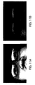
- FIG. 4A the camera 10 photographs a subject at a time when the first LED illuminating device 12 is lit by the first LED drive circuit 120.
- FIG. 4B is one example of an image for an odd-numbered frame Fo photographed by the photographing unit 140 of the camera 10, where R1 in the odd-numbered frame Fo is the pickup of light reflected by glasses etc. of a driver.
- the signal processing unit 104 then classifies the brightness of each of the pixels of the odd-numbered frame Fo into ten stages of, for example, 0 to 9, as shown in FIG. 4C .
- FIG. 5A the camera 10 photographs a subject at a time when the second LED illuminating device 13 is lit by the second LED drive circuit 130.
- FIG. 5B is one example of an image for an even-numbered frame Fe photographed by the photographing unit 140 of the camera 10, where R2 is an even-numbered frame Fe is the pickup of light reflected by glasses etc. of the driver.
- the signal processing unit 104 then classifies the brightness of each of the pixels of the even-numbered frame Fe into ten stages of, for example, 0 to 9, as shown in FIG. 5C .
- the signal processing unit 104 compares the brightness of each pixel positioned at the same relative positions on the odd-numbered frame Fo and the even-numbered frame Fe and extracts pixels where the brightness for each relative position is low.
- the signal processing unit 104 extracts pixels positioned at the coordinate (0, 0) of the even-numbered frame Fe for which the brightness is low. Further, when the relative positions are both coordinate (0, 1), the brightness of the pixels at the odd-numbered frame Fo of FIG. 4C is 1, and the brightness of the pixels at the even-numbered frame Fe of FIG. 5C is 2. In this event, the signal processing unit 104 extracts pixels positioned at the coordinate (0, 1) of the odd-numbered frame Fo for which the brightness is low.
- the signal processing unit 104 compares brightness and extracts pixels for all of the coordinates of the odd-numbered frame Fo and the even-numbered frame Fe and generates one new facial image by an appropriately arraying of each of the extracted pixels.
- the signal processing unit 104 generates a facial image f0 shown in FIG. 6A for the example of the odd-numbered frame Fo shown in FIG. 4B and the even-numbered frame Fe shown in FIG. 5B .
- the vehicle-mounted camera 1 alternately lights the first LED illuminating device 12 and the second LED illuminating device 13 and the face of the driver is photographed at the photographing unit 140 in synchronism with the timing of the lighting of each of the illuminating devices.
- the signal processing unit 104 compares the brightness of each pixel positioned at the same respective relative positions on the odd-numbered frame and the even-numbered frame photographed by the photographing unit 140 and extracts pixels of low brightness positioned at each relative position.
- the signal processing unit 104 then synthesizes each extracted pixel and generates a new facial image.
- the picking up of reflected light of a high degree of brightness can therefore be reduced as shown in the example of a facial image f0 in FIG. 6A for the facial image newly created by the signal processing unit 104.
- ECU 2 is able to detect inattentive driving by the driver in a more accurate manner based on facial images after the reduction of the reflected light.
- the signal processing unit 104 extracts pixels of a low brightness positioned at regions where the reflected light is picked up in processing synthesizing a new facial image shown in the first embodiment. This then impedes each control process executed based on the facial image after synthesis.
- first exposure control processing In order to avoid this problem, it is necessary to control exposure time so that odd-numbered frames photographed at the time of lighting of the first LED illuminating device 12 and even-numbered frames photographed at the time of lighting of the second LED illuminating device 13 have substantially the same brightness.
- This kind of exposure control processing is referred to as "first exposure control processing" in the following.
- the overall structure of the vehicle-mounted camera system of the second embodiment that is an example of carrying out first exposure control processing is basically the same as the example shown in FIG. 1 .
- a first exposure control program for first exposure control processing and various setting values are also stored in the EEPROM 160 the vehicle-mounted camera 1 of the second embodiment is provided with.
- the EEPROM 160 stores a brightness difference maximum value BDmax, a brightness difference minimum value BDmin, a maximum exposure value ETmax, and a minimum exposure value ETmin as setting values.
- the brightness difference maximum value BDmax and the brightness difference minimum value BDmin indicate an maximum and a minimum of the permitted range for reducing the influence of reflected light on the facial image using synthesis processing by the signal processing unit 104 even when the brightness (average value) of odd-numbered frames and the brightness (average value) of even-numbered frames are different.
- the maximum exposure value ETmax and minimum exposure value ETmin indicate a maximum value and a minimum value for exposure time for which exposure of a facial image by the photographing unit 140 is appropriate.
- the exposure time is the maximum exposure value ETmax or more, the facial image is overexposed.
- the exposure time is less than the minimum exposure value ETmin, the facial image is underexposed.
- the facial image is exposed in an appropriate manner if the exposure time is less than the maximum exposure value ETmax and larger than the minimum exposure value ETmin.
- the CPU 101 reads out a first exposure control program from the EEPROM 160 and executes the first exposure control program, for example, every photographing interval (for example, 1/30 seconds) of the photographing unit 140.
- the CPU 101 obtains average values for brightness of each frame (step S11).
- the CPU 101then determines whether or not a "brightness difference" that is a value for the average value of the brightness of the even-numbered frames subtracted from the average value of the brightness of the odd-numbered frames is larger than the brightness difference maximum value BDmax (step S12).
- step S12 If the brightness difference is larger than the brightness difference maximum value BDmax (step S12: YES), the CPU 101determines whether or not the exposure time is greater than the maximum exposure value ETmax in order to determine whether or not the exposure time when photographing the odd-numbered frames is too long (step S 13).
- step S13: YES If the exposure time when photographing the odd-numbered frames is greater than the maximum exposure value ETmax (step S13: YES), then the odd-numbered frames are overexposed. The CPU 101 therefore reduces the exposure time by a prescribed time (step S14). Step S15 is then proceeded to. If the exposure time is shorter than the maximum exposure value ETmax (step S13: NO), the CPU 101 determines whether or not the exposure time is less than the minimum exposure value ETmin in order to determine whether or not the exposure time when photographing even-numbered frames is too short (step S15).
- step S15 If the exposure time when photographing even-numbered frames is less than the minimum exposure value ETmin (step S15: YES), the even-numbered frames are underexposed.
- the CPU 101 therefore increases the exposure time by a prescribed time (step S16), and the processing ends. If the exposure time is larger than the minimum exposure value ETmin (step S15: NO), the CPU 101 ends the processing.
- step S12 determines whether or not the brightness difference is smaller than the brightness difference minimum value BDmin (step S 17).
- step S17: NO If the brightness difference is greater than the brightness difference minimum value BDmin (step S17: NO), the CPU 101 ends the processing. If the brightness difference is smaller than the brightness difference minimum value BDmin (step S17: YES), the CPU 101 determines whether or not the exposure time is greater than the maximum exposure value ETmax in order to determine whether or not the exposure time when photographing the even-numbered frames is too long (step S18).
- step S 18 If the exposure time when photographing the even-numbered frames is greater than the maximum exposure value ETmax (step S 18: YES), then the even-numbered frames are overexposed.
- the CPU 101 therefore reduces the exposure time by a prescribed time (step S 19) and the processing proceeds to step S20. If the exposure time is shorter than the maximum exposure value ETmax (step S18: NO), the CPU 101 determines whether or not the exposure time when photographing odd-numbered frames is less than the minimum exposure value ETmin (step S20).
- step S20 If the exposure time when photographing odd-numbered frames is less than the minimum exposure value ETmin (step S20: YES), the odd-numbered frames are underexposed.
- the CPU 101 therefore increases the exposure time by a prescribed time (step S21), and the processing ends. If the exposure time is longer than the minimum exposure value ETmin (step S20: NO), the CPU 101 ends the processing.
- the CPU 101 therefore controls the exposure time when photographing odd-numbered frames and the exposure time when photographing even-numbered frames respectively so that the difference in brightness between the odd-numbered frames and the even-numbered frames becomes a prescribed value or less by repeating the first exposure control processing. It is therefore possible to sufficiently reduce the influence of reflected light picked up in the facial image of the driver by having the signal processing unit 104 synthesize new facial images using each frame photographed in this manner.
- the CPU 101 controls the exposure time when photographing each of the odd-numbered frames F3, F5, F7, F9 based on the brightness of each odd-numbered frame F1, F3, F5, F7 photographed immediately previously. Further, the CPU 101 controls the exposure time when photographing each even-numbered frame F4, F6, F8, F10 based on the brightness of each even-numbered frame F2, F4, F6, F8 photographed immediately previously.
- the brightness of each frame F1 to F10 is then obtained by calculating the average value of the brightness of each pixel within a detection frame T1 provided at each frame.
- an average value B1 for the brightness of an odd-numbered frame F1 photographed before executing the first first exposure control processing is substantially smaller than an average value B2 for an even-numbered frame F2.
- the brightness difference that is the average value B1 for the brightness of F1 with the average value B2 of the brightness of F2 subtracted is smaller than the brightness difference minimum value BDmin (step S17: YES).
- the CPU 101 therefore reduces the exposure time when photographing even-numbered frames in the processing of step S19 and increases the exposure time when photographing odd-numbered frames in the processing of step S21.
- the odd-numbered frame and the even-numbered frame photographed by the first round of the first exposure control processing are therefore the odd-numbered frame F3 and the even-numbered frame F4 as shown in FIG. 8A .
- the brightness difference between the frames F3 and F4 remains smaller than the brightness difference minimum value BDmin at the time of the brightness difference determination processing (processing of step S17) in the second round of the first exposure control processing.
- the CPU 101 therefore repeatedly executes the processing of steps S19 to S21 so as to change each exposure time to appropriate exposure times when photographing the odd-numbered frames and the even-numbered frames.
- the difference between an average value B9 for the brightness of an odd-numbered frame F9 and an average value B10 for the brightness of an even-numbered frame F10 substantially disappears in the brightness difference determination processing for the fifth round of the first exposure control processing.
- the odd-numbered frame F1shown in FIG. 9A and the even-numbered frame F2 shown in FIG. 9B are the same as each of the frames F1 and F2 photographed before execution of the first round of the first exposure control processing shown in FIG. 8A .
- Each of the frames F1 and F2 in FIGS. 9A and 9B are examples of images that pick up light reflected by the lenses of glasses etc. worn by the driver and R3 and R4 within each of the frames F1 and F2 show the picking up of reflected light by the respective lenses.
- the brightness difference between each of the frames F1 and F2 is substantial.
- a picked-up portion R5 of reflected light within the new facial image f1 is not reduced even in cases when synthesis processing is carried out by the signal processing unit 104 based on each of the frames F1 and F2.
- the odd-numbered frame F9 of FIG. 9D and the even-numbered frame F10 of FIG. 9E are the same as each of the frames F9 and F10 photographed before execution of the fifth round of the first exposure control processing shown in FIG. 8A .
- Each of the frames F9 and F10 of FIG. 9D and FIG. 9E are examples of images that take in reflected light due to the lenses of glasses etc. worn by the driver, where R6 and R7 in the drawing are portions that pick up light reflected by the lenses.
- the picking up of reflected light at the facial image can therefore be sufficiently reduced when the image synthesis processing of the signal processing unit 104 using each of the frames F9 and F10 is adopted as shown in FIG. 9F .
- the structure of the vehicle-mounted camera system of the third embodiment that is an example of carrying out the second exposure control processing is basically the same as the example shown in FIG. 1 .
- a second exposure control program for second exposure control processing is also stored in the EEPROM 160 the vehicle-mounted camera 1 of the third embodiment is provided with.
- the CPU 101 reads out the second exposure control program from the EEPROM 160 and executes the second exposure control program, for example, every frame period (for example, 1/30 seconds) of the photographing unit 140.
- the CPU 101 determines whether or not each exposure time when photographing odd-numbered frames or when photographing even-numbered frames is one third or more of the frame period (step S31). If each exposure time is one third or more of the frame period (step S31: YES), the CPU 101 shortens the exposure time by a prescribed duration (step S32) and ends processing. If the exposure time is less than one third of the frame period (step S31: NO), the CPU 101 ends the processing.
- the exposure time is set to be larger than one third of one frame period (for example, 1/30 seconds), the exposure time is too long. This means that it is therefore easy for light reflected by glasses etc. to be picked up by the facial image as shown in FIG. 11A . In this event, it is not possible to reduce the reflected light picked up by the facial image even if synthesis processing is implemented by the signal processing unit 104.
- the exposure time at the time of photographing using the second exposure control processing is taken to be one third or less of one frame period, the influence of reflected light picked up by the facial image can be reduced as shown in FIG. 11B .
- the vehicle-mounted camera 1 synthesizes new facial images where the extent to which reflected light is taken in is reduced and the ECU 2 then carries out various control using facial images after synthesis.
- the present invention is, however, by no means limited to these embodiments.
- image synthesis processing etc. can be implemented by devices other than the vehicle-mounted camera 1.
- the vehicle-mounted camera 1 photographs each frame showing the face of the driver at the time of alternate illumination by the two illuminating devices
- the ECU 2 synthesizes each frame so as to create one facial image, and this facial image is then utilized.
- the vehicle-mounted camera system of the fourth embodiment is basically the same as the example shown in FIG. 1 and includes a vehicle-mounted camera 1a and an ECU 2a.
- the ECU 2a shown in FIG. 12 includes a signal processing unit 21 and the control unit 22.
- the signal processing unit 21 extracts pixels of low brightness of the pixels of the odd-numbered frames and the even-numbered frames of which the relative positions are the same and generates a new image.
- the control unit 22 then executes substantially the same control operation as the ECU 2 of FIG. 1 based on the image synthesized by the signal processing unit 21.
- the circuit configuration of the vehicle-mounted camera 1a shown in FIG. 12 is basically the same as the vehicle-mounted camera 1 shown in FIG. 1 . However, unlike the signal processing unit 104 of FIG. 1 , a signal processing unit 104a of FIG. 12 does not carry out the processing for synthesizing a new facial image. It is also possible to adopt a configuration where the signal processing unit 104a obtains an average brightness for each facial image and adjusts the exposure time based on this average brightness.
- an image of the face illuminated by the first LED illuminating device 12 and an image of the face illuminated by the second LED illuminating device 13 are alternately provided from a driver 170a of the vehicle-mounted camera 1a to the ECU 2a every 1/30 seconds.
- the signal processing unit 21 of an ECU 2a extracts pixels of low brightness of pixels of the same relative positions on the odd-numbered frame images and the even-numbered frame images, synthesizes a new facial image where the extent to which reflected light is picked up is reduced, and provides the new facial image to the control unit 22.
- the control unit 22 specifies a region of this facial image that indicates the eyes.
- the control unit 22 detects when the driver takes their eyes off the road or appears to fall asleep by determining the direction of the line of sight of the driver based on this region and carries out control according to detection results. It is therefore also possible to sufficiently reduce the influence of the reflected light picked up by the facial image with this configuration.
- Processing executed by devices other than the vehicle-mounted camera 1 such as the ECU 2 in place of the vehicle-mounted camera 1 is not restricted to processing reducing the amount of reflected light picked up at the facial image.
- the first exposure control processing of the second embodiment or processing synchronizing times of lighting of each of the illuminating devices 12 and 13 can also be carried out.
- the frame period of the photographing unit 140 is not limited to 1/30 seconds and can be arbitrary (for example, 1/24 seconds, 1/15 seconds).
- the method the photographing unit 140 uses to transmit images is not limited to non-interlaced methods and can also be, for example, interlaced methods.
- the units for comparing the brightness of the same relative positions of the odd-numbered frames and the even-numbered frames are not limited to one pixel units and can also be block units constituted by a plurality of pixels. In this event, for example, the average brightness occurring at each block is obtained. Blocks, of the blocks positioned in the same relative positions, for which the average brightness is small, can then be extracted. It is therefore possible to advance the processing speed when synthesizing new facial images.
- the number of LED illuminating devices installed is not limited to 2, and can be three or more.
- the method for synthesizing the new facial image is not limited to synthesizing odd-numbered frames and even-numbered frames provided that the extent to which light reflected by lenses etc. is picked up can be sufficiently reduced.
Landscapes
- Engineering & Computer Science (AREA)
- Multimedia (AREA)
- Physics & Mathematics (AREA)
- Signal Processing (AREA)
- General Physics & Mathematics (AREA)
- Theoretical Computer Science (AREA)
- Health & Medical Sciences (AREA)
- Computing Systems (AREA)
- Mechanical Engineering (AREA)
- General Health & Medical Sciences (AREA)
- Ophthalmology & Optometry (AREA)
- Human Computer Interaction (AREA)
- Image Processing (AREA)
- Studio Devices (AREA)
- Traffic Control Systems (AREA)
- Image Analysis (AREA)
- Stroboscope Apparatuses (AREA)
- Fittings On The Vehicle Exterior For Carrying Loads, And Devices For Holding Or Mounting Articles (AREA)
Claims (6)
- An einem Fahrzeug aufgebaute Bildverarbeitungsvorrichtung mit
einer Vielzahl von Beleuchtungseinheiten (12, 13) zur Beleuchtung eines Subjekts,
einer Einschalteinheit (110) zum sequentiellen Einschalten der Vielzahl der Beleuchtungseinheiten zu verschiedenen Zeiten,
einer Fotografiereinheit (140) zum Fotografieren jeweiliger Bilder, die ein Subjekt zeigen, das durch jede Beleuchtungseinheit beleuchtet ist, die durch die Einschalteinheit zu den jeweiligen Zeiten eingeschaltet ist, und
einer Synthetisiereinheit (104) zum Erzeugen und Ausgeben eines das Subjekt zeigenden Bildes durch Extrahieren von Abschnitten geringster Helligkeit aus den Abschnitten jedes Bildes, die sich an denselben relativen Positionen auf jedem Bild befinden, das das durch die Fotografiereinheit (140) fotografierte Subjekt angibt, und durch Synthetisieren der extrahierten Abschnitte,
dadurch gekennzeichnet, dass
die Fotografiereinheit (140) eine Belichtungssteuereinheit (101) zum Erhalten einer Durchschnittshelligkeit für jedes Bild, das das durch die Fotografiereinheit aufgenommene Subjekt zeigt, und Steuerung einer Belichtungszeit der Fotografiereinheit beim Fotografieren von Bildern umfasst, sodass ein Absolutwert einer Differenz zwischen jeder erhaltenen Durchschnittshelligkeit kleiner oder gleich einem bestimmten Wert wird. - An einem Fahrzeug aufgebaute Bildverarbeitungsvorrichtung nach Anspruch 1, wobei zwei der Beleuchtungseinheiten vorgesehen sind,
die Einschalteinheit zum abwechselnden Einschalten der Beleuchtungseinheiten eingerichtet ist,
die Fotografiereinheit zum Fotografieren jeweiliger das Subjekt zeigender Bilder zu einer entsprechenden Zeit, wenn die entsprechende Beleuchtungseinheit durch die Einschalteinheit eingeschaltet ist, eingerichtet ist, und
die Synthetisiereinheit zum Extrahieren von Abschnitten der geringsten Helligkeit aus Abschnitten, die an denselben jeweiligen relativen Positionen auf jedem ungeradzahligen fotografierten Subjektbild und jedem geradzahligen fotografierten Subjektbild positioniert sind, die durch die Fotografiereinheit aufgenommen sind, und zur Erzeugung eines neuen das Subjekt zeigenden Bildes durch Synthetisieren der extrahierten Abschnitte eingerichtet ist. - An einem Fahrzeug aufgebaute Bildverarbeitungsvorrichtung nach Anspruch 1, wobei die Synthetisiereinheit zum Vergleichen der Helligkeit von an denselben relativen Positionen positionierten Bildelementen auf jedem das Subjekt zeigenden Bild, Extrahieren von Bildelementen der geringsten Helligkeit und Synthetisieren jedes extrahierten Bildelements eingerichtet ist.
- An einem Fahrzeug aufgebaute Bildverarbeitungsvorrichtung nach Anspruch 1, wobei die Synthetisiereinheit zum Teilen jedes Bildes, das das durch die Fotografiereinheit aufgenommene Subjekt zeigt, in eine Vielzahl von Blöcken, Vergleichen der Helligkeit jedes an derselben relativen Position auf dem jeweiligen Bild positionierten Blocks, Extrahieren von Blöcken der geringsten Helligkeit und Synthetisieren der extrahierten Blöcke eingerichtet ist.
- An einem Fahrzeug aufgebaute Bildverarbeitungsvorrichtung nach Anspruch 1, ferner mit einer Steuereinheit zur Ausführung einer bestimmten Steuerung beruhend auf einem Bild eines Auges, das in einem neuen durch die Synthetisiereinheit synthetisierten Bild enthalten ist.
- Verfahren zur Steuerung einer an einem Fahrzeug aufgebauten Bildverarbeitungsvorrichtung, mit
einem Einschaltschritt des sequentiellen Einschaltens einer Vielzahl von Beleuchtungseinheiten (12, 13) zu unterschiedlichen Zeiten,
einem Fotografierschritt des Fotografierens jeweiliger Bilder, die ein durch ein jeweilige Beleuchtungseinheit beleuchtetes Subjekt zeigen, die zu entsprechenden Zeiten in dem Einschaltschritt eingeschaltet wird, und
einem Synthetisierschritt des Erzeugens und Ausgebens eines neuen das Subjekt zeigenden Bildes durch Extrahieren von Abschnitten geringster Helligkeit aus den Abschnitten jedes Bildes, die an denselben relativen Positionen auf jedem Bild positioniert sind, das das in dem Fotografierschritt fotografierte Subjekt zeigt, und durch Synthetisieren der extrahierten Abschnitte,
dadurch gekennzeichnet, dass
der Fotografierschritt einen Belichtungssteuerschritt des Erhaltens einer Durchschnittshelligkeit für jedes Bild, das das in dem Fotografierschritt aufgenommene Subjekt zeigt (S11), und ein Steuern einer Belichtungszeit umfasst, wenn Bilder in dem Fotografierschritt fotografiert werden, sodass ein Absolutwert einer Differenz zwischen jeder erhaltenen Durchschnittshelligkeit kleiner oder gleich einem bestimmten Wert wird (S14, S16, S19, S21).
Applications Claiming Priority (2)
| Application Number | Priority Date | Filing Date | Title |
|---|---|---|---|
| JP2006304604A JP4356733B2 (ja) | 2006-11-09 | 2006-11-09 | 車載用画像処理装置とその制御方法 |
| PCT/JP2007/071837 WO2008056789A1 (en) | 2006-11-09 | 2007-11-09 | On-vehicle image-processing device and control method for on-vehicle image-processing device |
Publications (3)
| Publication Number | Publication Date |
|---|---|
| EP2053845A1 EP2053845A1 (de) | 2009-04-29 |
| EP2053845A4 EP2053845A4 (de) | 2011-03-02 |
| EP2053845B1 true EP2053845B1 (de) | 2012-08-01 |
Family
ID=39364599
Family Applications (1)
| Application Number | Title | Priority Date | Filing Date |
|---|---|---|---|
| EP07831568A Not-in-force EP2053845B1 (de) | 2006-11-09 | 2007-11-09 | Mitgeführte Bildverarbeitungsvorrichtung und Steuerungsverfahren für die mitgeführte Bildverarbeitungsvorrichtung |
Country Status (4)
| Country | Link |
|---|---|
| US (1) | US8350903B2 (de) |
| EP (1) | EP2053845B1 (de) |
| JP (1) | JP4356733B2 (de) |
| WO (1) | WO2008056789A1 (de) |
Families Citing this family (25)
| Publication number | Priority date | Publication date | Assignee | Title |
|---|---|---|---|---|
| JP4780088B2 (ja) * | 2007-11-09 | 2011-09-28 | アイシン精機株式会社 | 顔画像撮像装置、顔画像撮像方法、及びそのプログラム |
| JP5033014B2 (ja) * | 2008-02-14 | 2012-09-26 | パナソニック株式会社 | 顔認証装置 |
| KR100936334B1 (ko) * | 2008-06-11 | 2010-01-12 | 현대자동차주식회사 | 얼굴 검출 시스템 |
| JP4666062B2 (ja) * | 2008-11-17 | 2011-04-06 | 株式会社デンソー | 画像撮影装置および方法 |
| JP5429358B2 (ja) * | 2010-03-01 | 2014-02-26 | コニカミノルタ株式会社 | ゴースト検出装置およびそれを用いる撮像装置、ゴースト検出方法、および、ゴースト除去方法 |
| JP5818409B2 (ja) * | 2010-06-17 | 2015-11-18 | キヤノン株式会社 | 眼底撮像装置及びその制御方法 |
| KR101820497B1 (ko) * | 2011-07-27 | 2018-01-22 | 삼성디스플레이 주식회사 | 표시 장치 및 그 구동 방법 |
| JP5345660B2 (ja) * | 2011-09-08 | 2013-11-20 | 本田技研工業株式会社 | 車載機器特定装置 |
| JP5761074B2 (ja) * | 2012-02-24 | 2015-08-12 | 株式会社デンソー | 撮像制御装置及びプログラム |
| US20130342694A1 (en) * | 2012-06-25 | 2013-12-26 | Tandent Vision Science, Inc. | Method and system for use of intrinsic images in an automotive driver-vehicle-assistance device |
| JP5820359B2 (ja) * | 2012-11-28 | 2015-11-24 | フリュー株式会社 | 撮影画像編集装置、画像処理端末、撮影画像編集装置の制御方法、撮影画像編集装置および画像処理端末制御プログラム、およびそれらのコンピュータ読み取り可能な記録媒体 |
| JP6092371B2 (ja) * | 2013-04-10 | 2017-03-08 | 株式会社東芝 | 電子機器および画像処理方法 |
| DE102014113256A1 (de) * | 2014-09-15 | 2016-03-17 | Carl Zeiss Microscopy Gmbh | Bildaufnahmevorrichtung und Verfahren zur Bildaufnahme mit Reflexunterdrückung |
| US9846921B2 (en) * | 2014-09-29 | 2017-12-19 | The Boeing Company | Dynamic image masking system and method |
| FR3044504A1 (fr) * | 2015-12-01 | 2017-06-02 | Valeo Comfort & Driving Assistance | Dispositif de capture d'image et dispositif de surveillance d'un conducteur utilisant un tel dispositif de capture d'image |
| JP6289439B2 (ja) * | 2015-12-16 | 2018-03-07 | オムロンオートモーティブエレクトロニクス株式会社 | 画像処理装置 |
| JP6650829B2 (ja) * | 2016-05-23 | 2020-02-19 | 日本電信電話株式会社 | 画像検索装置、方法、及びプログラム |
| US20190141264A1 (en) * | 2016-05-25 | 2019-05-09 | Mtekvision Co., Ltd. | Driver's eye position detecting device and method, imaging device having image sensor with rolling shutter driving system, and illumination control method thereof |
| KR102371591B1 (ko) * | 2016-10-06 | 2022-03-07 | 현대자동차주식회사 | 운전자 상태 판단 장치 및 방법 |
| JP7078386B2 (ja) * | 2017-12-07 | 2022-05-31 | 矢崎総業株式会社 | 画像処理装置 |
| JP6894880B2 (ja) | 2018-11-07 | 2021-06-30 | 矢崎総業株式会社 | 監視システム |
| DE102020007064B4 (de) * | 2020-11-19 | 2022-08-11 | Daimler Truck AG | Verfahren zum Kalibrieren einer ersten Beleuchtungseinrichtung, einer zweiten Beleuchtungseinrichtung und eines optischen Sensors, Steuereinrichtung zur Durchführung eines solchen Verfahrens, Kalibrierungsvorrichtung mit einer solchen Steuereinrichtung und Kraftfahrzeug mit einer solchen Kalibrierungsvorrichtung |
| WO2022224423A1 (ja) * | 2021-04-23 | 2022-10-27 | 三菱電機株式会社 | 車載用露光制御装置及び露光制御方法 |
| JP2023041097A (ja) | 2021-09-13 | 2023-03-24 | 矢崎総業株式会社 | 検出システム |
| WO2025009720A1 (ko) * | 2023-07-06 | 2025-01-09 | 삼성전자주식회사 | 엘이디를 제어하기 위한 데이터 세트들의 순서를 조절하기 위한 전자 장치, 방법, 및 컴퓨터 판독 가능 저장 매체 |
Family Cites Families (13)
| Publication number | Priority date | Publication date | Assignee | Title |
|---|---|---|---|---|
| DE3803916A1 (de) * | 1988-02-09 | 1989-08-17 | Messerschmitt Boelkow Blohm | Verfahren und vorrichtung zur ermittlung der fahrtauglichkeit eines fahrzeugfuehrers |
| JPH06323832A (ja) | 1993-05-13 | 1994-11-25 | Nissan Motor Co Ltd | 車両用インターフェイス |
| JP3364816B2 (ja) | 1994-12-27 | 2003-01-08 | 三菱電機株式会社 | 画像処理装置 |
| US6088470A (en) * | 1998-01-27 | 2000-07-11 | Sensar, Inc. | Method and apparatus for removal of bright or dark spots by the fusion of multiple images |
| GB9823977D0 (en) * | 1998-11-02 | 1998-12-30 | Scient Generics Ltd | Eye tracking method and apparatus |
| JP2002352229A (ja) * | 2001-05-30 | 2002-12-06 | Mitsubishi Electric Corp | 顔部位検出装置 |
| US7206435B2 (en) * | 2002-03-26 | 2007-04-17 | Honda Giken Kogyo Kabushiki Kaisha | Real-time eye detection and tracking under various light conditions |
| JP2004070512A (ja) | 2002-08-02 | 2004-03-04 | Nissan Motor Co Ltd | 運転者の顔状態検出装置 |
| US7280678B2 (en) * | 2003-02-28 | 2007-10-09 | Avago Technologies General Ip Pte Ltd | Apparatus and method for detecting pupils |
| US7777778B2 (en) * | 2004-10-27 | 2010-08-17 | Delphi Technologies, Inc. | Illumination and imaging system and method |
| JP4122380B2 (ja) | 2005-04-13 | 2008-07-23 | 国立大学法人 北海道大学 | 海藻の分析方法 |
| US7646422B2 (en) * | 2006-10-04 | 2010-01-12 | Branislav Kisacanin | Illumination and imaging system with glare reduction and method therefor |
| JP4876080B2 (ja) * | 2008-01-25 | 2012-02-15 | 富士重工業株式会社 | 環境認識装置 |
-
2006
- 2006-11-09 JP JP2006304604A patent/JP4356733B2/ja active Active
-
2007
- 2007-11-09 WO PCT/JP2007/071837 patent/WO2008056789A1/ja not_active Ceased
- 2007-11-09 US US12/442,076 patent/US8350903B2/en active Active
- 2007-11-09 EP EP07831568A patent/EP2053845B1/de not_active Not-in-force
Also Published As
| Publication number | Publication date |
|---|---|
| EP2053845A1 (de) | 2009-04-29 |
| JP4356733B2 (ja) | 2009-11-04 |
| JP2008123137A (ja) | 2008-05-29 |
| US8350903B2 (en) | 2013-01-08 |
| EP2053845A4 (de) | 2011-03-02 |
| US20090251534A1 (en) | 2009-10-08 |
| WO2008056789A1 (en) | 2008-05-15 |
Similar Documents
| Publication | Publication Date | Title |
|---|---|---|
| EP2053845B1 (de) | Mitgeführte Bildverarbeitungsvorrichtung und Steuerungsverfahren für die mitgeführte Bildverarbeitungsvorrichtung | |
| RU2627933C2 (ru) | Устройство захвата изображения и способ управления им | |
| US7573505B2 (en) | Image capturing apparatus, control method therefor, program, and storage medium | |
| CN107431747B (zh) | 摄像装置 | |
| CN101295355A (zh) | 面部图像获取装置 | |
| JP6722041B2 (ja) | 監視システム | |
| CN102971776A (zh) | 障碍物检测系统以及方法、障碍物检测装置 | |
| JP5551824B2 (ja) | 撮像装置 | |
| KR20050043615A (ko) | 프레임 그래버 | |
| JP2008252401A (ja) | 撮像システム、撮像方法、および撮像プログラム | |
| JPWO2005064922A1 (ja) | 撮像システム | |
| JP5189913B2 (ja) | 画像処理装置 | |
| EP1530367A1 (de) | Bildaufnahmesystem | |
| JP2007286943A (ja) | 信号灯検出装置 | |
| CN102074007B (zh) | 车辆用图像处理装置 | |
| JP2017112486A (ja) | 画像処理装置 | |
| JP2009165081A (ja) | ステレオカメラシステム | |
| JP5222779B2 (ja) | ナンバープレート認識装置 | |
| JP2005229317A (ja) | 画像表示システム及び撮像装置 | |
| JP6323472B2 (ja) | 動画撮像装置 | |
| CN101032169B (zh) | 车辆用图像处理装置 | |
| CN111131667B (zh) | 进行闪烁检测的摄像设备及其控制方法和存储介质 | |
| CN117351530A (zh) | 人脸识别方法、介质、电子设备和程序产品 | |
| JP2009042098A (ja) | 画像処理式物体検出装置 | |
| JP6906084B2 (ja) | カラーカメラ装置及び光学部品 |
Legal Events
| Date | Code | Title | Description |
|---|---|---|---|
| PUAI | Public reference made under article 153(3) epc to a published international application that has entered the european phase |
Free format text: ORIGINAL CODE: 0009012 |
|
| 17P | Request for examination filed |
Effective date: 20090313 |
|
| AK | Designated contracting states |
Kind code of ref document: A1 Designated state(s): DE FR GB |
|
| AX | Request for extension of the european patent |
Extension state: AL BA HR MK RS |
|
| A4 | Supplementary search report drawn up and despatched |
Effective date: 20110131 |
|
| RIC1 | Information provided on ipc code assigned before grant |
Ipc: G08G 1/16 20060101ALI20110125BHEP Ipc: G03B 15/03 20060101AFI20110125BHEP Ipc: B60K 28/02 20060101ALI20110125BHEP Ipc: G06K 9/00 20060101ALI20110125BHEP Ipc: A61B 3/14 20060101ALI20110125BHEP Ipc: G06T 7/00 20060101ALI20110125BHEP Ipc: H04N 5/238 20060101ALI20110125BHEP Ipc: B60R 11/04 20060101ALI20110125BHEP Ipc: G06T 1/00 20060101ALI20110125BHEP Ipc: G06T 3/00 20060101ALI20110125BHEP |
|
| REG | Reference to a national code |
Ref country code: DE Ref legal event code: R079 Ref document number: 602007024411 Country of ref document: DE Free format text: PREVIOUS MAIN CLASS: H04N0005238000 Ipc: G03B0015050000 |
|
| RIC1 | Information provided on ipc code assigned before grant |
Ipc: A61B 3/14 20060101ALI20111222BHEP Ipc: G06K 9/00 20060101ALI20111222BHEP Ipc: G08G 1/16 20060101ALI20111222BHEP Ipc: G03B 15/05 20060101AFI20111222BHEP Ipc: H04N 5/225 20060101ALI20111222BHEP Ipc: G06T 5/50 20060101ALI20111222BHEP Ipc: B60R 11/04 20060101ALI20111222BHEP Ipc: H04N 5/235 20060101ALI20111222BHEP Ipc: H04N 5/232 20060101ALI20111222BHEP |
|
| RTI1 | Title (correction) |
Free format text: ON-VEHICLE IMAGE-PROCESSING DEVICE AND CONTROL METHOD FOR ON-VEHICLE IMAGE-PROCESSING DEVICE |
|
| GRAP | Despatch of communication of intention to grant a patent |
Free format text: ORIGINAL CODE: EPIDOSNIGR1 |
|
| DAX | Request for extension of the european patent (deleted) | ||
| GRAS | Grant fee paid |
Free format text: ORIGINAL CODE: EPIDOSNIGR3 |
|
| GRAA | (expected) grant |
Free format text: ORIGINAL CODE: 0009210 |
|
| AK | Designated contracting states |
Kind code of ref document: B1 Designated state(s): DE FR GB |
|
| REG | Reference to a national code |
Ref country code: GB Ref legal event code: FG4D |
|
| REG | Reference to a national code |
Ref country code: DE Ref legal event code: R096 Ref document number: 602007024411 Country of ref document: DE Effective date: 20120927 |
|
| PLBE | No opposition filed within time limit |
Free format text: ORIGINAL CODE: 0009261 |
|
| STAA | Information on the status of an ep patent application or granted ep patent |
Free format text: STATUS: NO OPPOSITION FILED WITHIN TIME LIMIT |
|
| 26N | No opposition filed |
Effective date: 20130503 |
|
| GBPC | Gb: european patent ceased through non-payment of renewal fee |
Effective date: 20121109 |
|
| REG | Reference to a national code |
Ref country code: DE Ref legal event code: R097 Ref document number: 602007024411 Country of ref document: DE Effective date: 20130503 |
|
| PG25 | Lapsed in a contracting state [announced via postgrant information from national office to epo] |
Ref country code: GB Free format text: LAPSE BECAUSE OF NON-PAYMENT OF DUE FEES Effective date: 20121109 |
|
| PGFP | Annual fee paid to national office [announced via postgrant information from national office to epo] |
Ref country code: DE Payment date: 20131106 Year of fee payment: 7 Ref country code: FR Payment date: 20131108 Year of fee payment: 7 |
|
| REG | Reference to a national code |
Ref country code: DE Ref legal event code: R119 Ref document number: 602007024411 Country of ref document: DE |
|
| REG | Reference to a national code |
Ref country code: FR Ref legal event code: ST Effective date: 20150731 |
|
| PG25 | Lapsed in a contracting state [announced via postgrant information from national office to epo] |
Ref country code: DE Free format text: LAPSE BECAUSE OF NON-PAYMENT OF DUE FEES Effective date: 20150602 |
|
| PG25 | Lapsed in a contracting state [announced via postgrant information from national office to epo] |
Ref country code: FR Free format text: LAPSE BECAUSE OF NON-PAYMENT OF DUE FEES Effective date: 20141201 |