WO2022224423A1 - 車載用露光制御装置及び露光制御方法 - Google Patents
車載用露光制御装置及び露光制御方法 Download PDFInfo
- Publication number
- WO2022224423A1 WO2022224423A1 PCT/JP2021/016404 JP2021016404W WO2022224423A1 WO 2022224423 A1 WO2022224423 A1 WO 2022224423A1 JP 2021016404 W JP2021016404 W JP 2021016404W WO 2022224423 A1 WO2022224423 A1 WO 2022224423A1
- Authority
- WO
- WIPO (PCT)
- Prior art keywords
- mask
- face
- passenger
- exposure control
- detection unit
- Prior art date
Links
- 238000000034 method Methods 0.000 title claims description 35
- 238000001514 detection method Methods 0.000 claims abstract description 155
- 238000003384 imaging method Methods 0.000 claims abstract description 34
- 230000001815 facial effect Effects 0.000 claims description 43
- 238000013459 approach Methods 0.000 claims description 23
- 238000010586 diagram Methods 0.000 description 13
- 238000012544 monitoring process Methods 0.000 description 12
- 239000003086 colorant Substances 0.000 description 4
- 238000002834 transmittance Methods 0.000 description 4
- 230000002950 deficient Effects 0.000 description 2
- 230000000694 effects Effects 0.000 description 2
- 239000007787 solid Substances 0.000 description 1
Images


Classifications
-
- H—ELECTRICITY
- H04—ELECTRIC COMMUNICATION TECHNIQUE
- H04N—PICTORIAL COMMUNICATION, e.g. TELEVISION
- H04N23/00—Cameras or camera modules comprising electronic image sensors; Control thereof
- H04N23/60—Control of cameras or camera modules
-
- H—ELECTRICITY
- H04—ELECTRIC COMMUNICATION TECHNIQUE
- H04N—PICTORIAL COMMUNICATION, e.g. TELEVISION
- H04N23/00—Cameras or camera modules comprising electronic image sensors; Control thereof
- H04N23/70—Circuitry for compensating brightness variation in the scene
-
- H—ELECTRICITY
- H04—ELECTRIC COMMUNICATION TECHNIQUE
- H04N—PICTORIAL COMMUNICATION, e.g. TELEVISION
- H04N23/00—Cameras or camera modules comprising electronic image sensors; Control thereof
- H04N23/70—Circuitry for compensating brightness variation in the scene
- H04N23/76—Circuitry for compensating brightness variation in the scene by influencing the image signals
Definitions
- the present disclosure relates to an in-vehicle exposure control device and an exposure control method.
- an in-vehicle exposure control device that controls the exposure of a captured image of a driver's face when it is determined that the driver is wearing a mask on the captured image.
- An exposure control unit that controls the exposure of a captured image provided by the in-vehicle exposure control device controls, for example, a predetermined region vertically and downwardly below the horizontal edge extracted at the edge of the mask (that is, the mask is present).
- a predetermined region vertically and downwardly below the horizontal edge extracted at the edge of the mask (that is, the mask is present).
- Passengers including the driver, may wear not only masks but also various other accessories (such as sunglasses). Also, the color of the mask is not limited to white, and various other colors may be worn. However, Patent Document 1 does not specifically disclose a method for appropriately controlling exposure even when accessories other than masks or masks other than white are attached.
- the present disclosure has been made to solve the above-described problems, and provides an in-vehicle exposure control apparatus and exposure control capable of appropriately controlling exposure corresponding to various accessories worn by a passenger. Aim to get a method.
- An in-vehicle exposure control apparatus includes an imaging unit that acquires a captured image of a passenger that is output from an imaging device that captures an image of a passenger in a vehicle; A face detection unit for detecting face information of the passenger from an image; a face parts detection unit for detecting face parts from the face information detected by the face detection unit; and face parts detected by the face parts detection unit. and a face part detection accuracy detection unit that detects the detection accuracy of the facial parts detected by the face parts detection accuracy detection unit, and the face parts for which the detection accuracy of the facial parts detected by the facial parts detection accuracy detection unit is equal to or higher than a predetermined detection accuracy are selected as exposure control target face parts.
- an exposure control target face part determination unit that outputs a determination result; a brightness detection unit that detects the average brightness of the exposure control target face part; and an exposure controller for controlling exposure.
- an exposure control method includes steps of acquiring a captured image of the passenger output from an imaging device that captures an image of the passenger boarding the vehicle; detecting a face part from the face information; detecting a detection accuracy of the face part; The steps of determining the facial parts, detecting the average luminance of the facial parts subject to exposure control, and controlling the exposure so that the average luminance approaches the target luminance are provided.
- a vehicle-mounted exposure control apparatus and exposure control method determine whether or not a mask is worn using a passenger's face information, and adjust the average brightness detected from the determination result to be close to a predetermined target brightness. Since the exposure is controlled, there is an effect that the exposure can be appropriately controlled even when the passenger wears the accessory and covers the facial parts.
- FIG. 1 is a schematic diagram of a DMS 100 to which a vehicle-mounted exposure control device 10 of Embodiment 1 is applied;
- FIG. 4 is a flowchart of an exposure control method according to Embodiment 1;
- FIG. 10 is a diagram showing an example of face parts for exposure control in step S104;
- FIG. 10 is a diagram showing an example of face parts for exposure control in step S104;
- FIG. 10 is a diagram showing an example of face parts for exposure control in step S104;
- FIG. 10 is a diagram showing an example of face parts for exposure control in step S104;
- FIG. FIG. 10 is a diagram showing an example of face parts for exposure control in step S104;
- FIG. FIG. 10 is a diagram showing an example of face parts for exposure control in step S104;
- FIG. 11 is a schematic diagram of a DMS 200 to which an in-vehicle exposure control device 20 of Embodiment 2 is applied; 9 is a flowchart of an exposure control method according to Embodiment 2; FIG. 10 is a diagram showing the range of each area detected in steps S203 and S204; FIG. 11 is a schematic diagram of a DMS 300 to which an in-vehicle exposure control device 30 of Embodiment 3 is applied; 10 is a flowchart of an exposure control method according to Embodiment 3;
- FIG. 1 is a schematic diagram of a DMS (Driver Monitoring System) 100 to which a vehicle-mounted exposure control apparatus 10 according to Embodiment 1 is applied.
- the DMS 100 is mounted on a vehicle and performs various monitoring processes for passengers including the driver on board the vehicle.
- the monitoring process of the passenger of the DMS 100 includes, for example, determination of the passenger's condition, personal authentication of the passenger, and the like.
- the DMS 100 includes an imaging device 1 and an in-vehicle exposure control device 10 connected to the imaging device 1 via a network.
- the imaging device 1 is a camera that captures an image of a passenger and outputs the captured image to the in-vehicle exposure control device 10 .
- the in-vehicle exposure control device 10 performs exposure control of the captured image output from the imaging device 1 .
- the in-vehicle exposure control device 10 includes an imaging unit 2 , a face detection unit 3 , a face parts detection unit 4 , a face parts detection accuracy detection unit 5 , an exposure control target face parts determination unit 6 , and a luminance detection unit 7 . , and an exposure control unit 8 .
- the imaging unit 2 acquires the captured image output from the imaging device 1 .
- the imaging unit 2 then outputs the captured image to the face detection unit 3 .
- the face detection unit 3 uses the captured image output from the imaging unit 2 to detect the passenger's face information. Then, the face detection section 3 outputs the detection result of detecting the face information to the face part detection section 4 .
- the face part detection unit 4 uses the detection results output from the face detection unit 3 to detect face parts (eg, eyes, nose, mouth, etc.) that are characteristic points of face information necessary for monitoring processing. Then, the face part detection section 4 outputs the detection result of detecting the face part to the face part detection accuracy detection section 5 .
- face parts eg, eyes, nose, mouth, etc.
- the face part detection accuracy detection unit 5 uses the detection result output from the face part detection unit 4 to detect the detection accuracy that indicates the accuracy of the face part detection result. Then, the face part detection accuracy detection unit 5 outputs the detection result of the detection accuracy to the exposure control target face part determination unit 6 .
- the exposure control target face part determination unit 6 uses the detection result output from the face part detection accuracy detection unit 5 to determine whether the detection accuracy has reached a predetermined first detection accuracy. A facial part that has reached one detection accuracy is selected as an exposure control target facial part whose exposure is to be controlled. Then, the exposure control target facial part determination unit 6 outputs the result to the brightness detection unit 7 .
- the first detection accuracy does not reach the second detection accuracy required for the monitoring process, but it is possible to reach the second detection accuracy for facial parts by controlling the exposure. It is the possible detection accuracy.
- the brightness detection unit 7 uses the result output from the exposure control target facial part determination unit 6 to detect the average brightness of the exposure control target facial part.
- the luminance detection unit 7 then outputs the detection result of the average luminance to the exposure control unit 8 .
- the exposure control unit 8 uses the detection result detected by the luminance detection unit 7 to control exposure so that the average luminance approaches a predetermined target luminance.
- the target luminance is predetermined as luminance with which facial parts can be detected with high detection accuracy, and is luminance at which the detection accuracy of facial parts is equal to or higher than the second detection accuracy required for monitoring processing. is set to
- FIG. 2 is a flow chart of the exposure control method of the first embodiment.
- the exposure control method according to the first embodiment includes a step of acquiring a captured image of the passenger, which is output from the imaging device 1 that captures the passenger riding in the vehicle, when the passenger is wearing the accessory. a step S101 for detecting facial information of the passenger from the captured image; a step S102 for detecting facial parts from the facial information; a step S103 for detecting the detection accuracy of the facial parts; A step S104 of determining a face part having a detection accuracy equal to or higher than a predetermined detection accuracy as an exposure control target face part; A step S106 for controlling the is provided.
- step S101 of detecting the face information of the passenger from the captured image the captured image output by the step of outputting the captured image of the passenger output from the imaging device for capturing the image of the passenger on board the vehicle. is used to detect the face information of the passenger.
- step S102 of detecting facial parts from facial information facial parts are detected using the passenger's facial information detected in step S101.
- step S103 of detecting the detection accuracy of the face part the detection accuracy indicating the accuracy of the detection result of the face part is detected using the face part detected in step S102.
- the detection accuracy is detected, for example, by calculating based on the rate at which the position of the face part matches the position of the face part stored in advance.
- step S104 a face part whose detection accuracy is equal to or higher than a predetermined detection accuracy is determined to be an exposure control target face part. It is then determined whether or not the first detection accuracy has been reached, and the facial part that has reached the first detection accuracy is selected as an exposure control target facial part whose exposure is to be controlled.
- FIG. 3 to 6 are diagrams showing examples of facial parts to be subjected to exposure control in step S104.
- the face parts that have reached the first detection accuracy are indicated by square frames, and the face parts that have not reached the first detection accuracy (defective part B) are indicated by solid square frames. It is shown enclosed.
- FIG. 3 shows a case where the passenger's right eye is shielded by an eyepatch or the like. In this case, the unshielded left eye and mouth are determined as the exposure control target face part A, and the shielded right eye is determined as the missing part B.
- FIG. FIG. 4 shows a case where the passenger's eyes are shielded by sunglasses or the like with low transmittance.
- the unshielded mouth is determined to be the exposure control target face part A, and since the transmittance of the sunglasses that shield the eyes is low, it is not possible to detect the eyes through the sunglasses. Both eyes are determined to be missing parts B.
- FIG. 5 shows a case where the eyes of the passenger are shielded by sunglasses or the like with high transmittance and the mouth is shielded by a mask or the like. In this case, since the sunglasses that shield the eyes have a high transmittance, it is possible to detect the eyes through the sunglasses, so the detection accuracy of the detected eyes has reached the first detection accuracy. is determined as the exposure control target part A, and the blocked mouth is determined as the defective part B.
- FIG. 6 shows a case where the passenger's right eye is covered with an eyepatch or the like and the mouth is covered with a mask or the like.
- the unshielded left eye is determined as the exposure control target face part A
- the shielded right eye and mouth are determined as the missing part B.
- step S105 for detecting the average brightness of the exposure control target facial parts the average brightness of the exposure control target facial parts determined in step S104 is detected.
- step S106 for controlling exposure so that the average brightness reaches the target brightness if the average brightness of the exposure control target facial part detected in step S105 does not reach the predetermined target brightness, the average brightness is reduced to the target brightness. Exposure is controlled by adjusting the exposure time and gain so as to approach the target brightness.
- the detection accuracy of the face part required for the monitoring process is increased by controlling the exposure. It is determined whether or not the first detection accuracy, which is a detection accuracy capable of reaching the second detection accuracy, has been reached, and the face part that has reached the first detection accuracy is set as the face part subject to exposure control.
- the average brightness of the face part subject to exposure control is detected, and the exposure is controlled so that the average brightness approaches the target brightness.
- exposure can be appropriately controlled even when the occupant is wearing various accessories including a mask, and the monitoring process can be smoothed and accurate.
- FIG. 5 exposure can be appropriately controlled even when a mask and sunglasses are worn at the same time.
- the in-vehicle exposure control apparatus 10 and the exposure control method of Embodiment 1 detect facial parts using facial information of a passenger, and the average brightness of the facial parts reaching a predetermined detection accuracy is Since the exposure is controlled so as to approach the target brightness, the exposure can be appropriately controlled even when the facial parts are blocked by the accessories worn by the passenger.
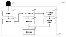
- FIG. 7 is a schematic diagram of a DMS 200 to which the in-vehicle exposure control device 20 of Embodiment 2 is applied. As shown in FIG. 7, although it is different from the first embodiment in that a mask detection unit 24 is provided, the rest except for the face parts detection unit 4, the face parts detection accuracy detection unit 5, and the exposure control target face parts determination unit 6. is the same as that of the first embodiment.
- the mask detection unit 24 compares the face information output from the face detection unit 23 with pre-stored face information, and detects whether or not a mask is worn. Then, the mask detection section 24 outputs the detection result to the luminance detection section 25 .
- the luminance detection unit 25 detects the average luminance of the area E of the face area C excluding the mask area D, and detects the average luminance of the area E without the mask. , the average brightness of the face region C is detected. The luminance detection unit 25 then outputs the detection result of the average luminance to the exposure control unit 26 .
- the exposure control unit 26 uses the detection result output from the brightness detection unit 25 to control exposure so that the average brightness approaches the target brightness.
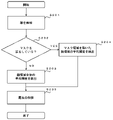
- FIG. 8 is a flow chart of the exposure control method of the second embodiment.
- An exposure control method according to Embodiment 2 includes the step of acquiring a captured image of a passenger in a vehicle output from an imaging device that captures an image of the passenger while the passenger is wearing an accessory.
- a step S201 of detecting face information of the passenger from the captured image a step S202 of detecting whether or not the passenger is wearing a mask from the face information, and if it is detected that the mask is worn, the face information has step S204 of detecting the average brightness of the area of the face area excluding the mask area covered by the mask (step S203), and detecting the average brightness of the face area C when it is detected that the mask is not worn;
- a step S205 is provided to control exposure so that the average luminance approaches the target luminance.
- the captured image output by the step of outputting the captured image of the passenger output from the imaging device that captures the image of the passenger on board the vehicle. is used to detect the face information of the passenger.
- step S202 for detecting whether or not the passenger is wearing a mask from the face information the face information detected in step S201 is compared with pre-stored face information to detect whether or not the passenger is wearing a mask.
- the pre-stored face information is, for example, face information when the passenger is not wearing a mask or face information when the passenger is wearing a mask.
- the mask worn by the passenger which is stored in advance in the face information, may be a white mask including a relatively light color such as yellow or light blue other than white, or a black mask such as navy blue or brown. , and various colors such as black masks, including relatively dark ones.
- step S202 If it is detected in step S202 that a mask is worn, the process proceeds to step S203 for detecting the average brightness of the face area of the face information, excluding the mask area blocked by the mask.
- step S203 the average luminance of the area E of the face area C excluding the mask area D is detected.
- step S202 If it is detected in step S202 that no mask is worn, the process proceeds to step S204 for detecting the average brightness of the face region C. In step S204, the average brightness of the face area C is detected.
- FIG. 9 is a diagram showing the range of each area detected in steps S203 and S204.
- a facial area C is an area of facial information of the passenger, and is a range indicated by a dotted line frame.
- the mask area D is the area of the face area C that is shielded by the mask, and the area within the solid line frame is the hatched area.
- an area E is an area of the face area C excluding the mask area D, and is a range indicated by a solid-line frame.
- step S205 which controls exposure so that the average luminance approaches the target luminance
- the exposure time is adjusted so that the average luminance approaches the target luminance. and control the exposure by adjusting the gain.
- the detected facial information of the passenger is compared with the pre-stored facial information.
- the area where the average brightness is detected is changed, and the exposure is controlled so that the average brightness of the area approaches the target brightness.
- the in-vehicle exposure control apparatus 20 and the exposure control method according to the second embodiment detect whether or not the mask is worn by using the face information of the occupant, and determine the area for detecting the average luminance based on whether or not the mask is worn.
- the exposure is controlled so that the average brightness of the relevant area approaches the target brightness, so even if the face parts are blocked by the mask worn by the passenger, the exposure can be controlled appropriately. It works.
- the face information detected in step S201 is compared with pre-stored face information. can do.
- FIG. 10 is a schematic diagram of a DMS 300 to which the in-vehicle exposure control device 30 of Embodiment 3 is applied. As shown in FIG. 10, it differs from the second embodiment in that a mask type identifying section 35 and a target luminance adjusting section 36 are provided, but other configurations are the same as those of the second embodiment.
- the mask detection unit 34 compares the face information output from the face detection unit 33 with pre-stored face information, and detects whether or not a mask is worn. Then, the mask detection section 34 outputs the detection result to the luminance detection section 37 . Further, when the mask detection unit 34 detects that the mask is attached, the detection result is output to the mask type identification unit 35 .
- the mask type identification unit 35 identifies the type of mask using the mask wearing detection result output from the mask detection unit 34 . Then, the mask type identifying section 35 outputs the identification result to the target luminance adjusting section 36 .
- the target brightness adjustment unit 36 uses the identification result output from the mask type identification unit 35 to adjust the target brightness according to the identified mask. Then, the target brightness adjustment section 36 outputs the adjusted target brightness to the exposure control section 38 .
- the exposure control unit 38 uses the detection result output from the brightness detection unit 37 to control exposure so that the average brightness approaches the target brightness. However, when the target brightness is adjusted by the target brightness adjustment unit 36, the exposure is controlled so that the average brightness approaches the adjusted target brightness output from the target brightness adjustment unit 36.
- FIG. 11 is a flow chart of the third embodiment.
- An exposure control method according to Embodiment 3 includes the step of obtaining a captured image of a passenger in a vehicle output from an imaging device that captures an image of the passenger while the passenger is wearing an accessory.
- a step S301 of detecting facial information of the passenger from the captured image a step S302 of detecting whether or not the passenger is wearing a mask from the facial information, and if it is detected that the mask is not worn, the facial information
- a step S303 of detecting the average luminance of the face area of the a step S307 of controlling the exposure so that the average luminance approaches the target luminance, and a step S307 of identifying the type of the mask if it is detected that the mask is attached.
- step S304 if the mask type is identified as a white mask, the target brightness is adjusted higher than when no mask is attached (step S305), and if the mask type is identified as a black mask. includes a step S306 of adjusting the target brightness to be lower than without the mask.
- the type of mask is identified in step S304 for identifying the type of mask.
- the method of identifying the type of mask is, for example, a method of detecting the color of the mask from the reflectance of the mask.
- a mask with a reflectance above a certain value can be classified as a white mask, and a mask with a reflectance below a certain value can be classified as a black mask.
- White masks include, in addition to white, relatively light colors such as yellow and light blue.
- the black mask includes not only black but also relatively dark colors such as navy blue and brown.
- the mask type may be identified based on a comparison between the detected mask information and pre-stored multiple types of mask information.
- step S305 the target luminance is adjusted higher than when no mask is attached.
- the white mask is attached, the brightness of the white mask is detected to be higher than that of the other face areas. Therefore, in step S305, the target brightness is adjusted to be higher than in the case of no mask.
- step S306 the target luminance is adjusted to be lower than when no mask is attached.
- the black mask is detected to be lower than the other facial areas, so in step S306, the target luminance is adjusted to be lower than when there is no mask.
- step 307 which controls exposure so that the average luminance approaches the target luminance
- the exposure time and gain are adjusted so that the average luminance approaches the target luminance. You control the exposure by adjusting the . However, if the target brightness has been adjusted in step S305 or step S306, exposure is controlled so that the average brightness approaches the target brightness adjusted in steps S305 and S306.
- the exposure control method of Embodiment 3 the type of mask worn by the passenger is identified, the target brightness is adjusted according to the type, and the exposure is controlled based on the target brightness. Therefore, the exposure can be appropriately controlled regardless of the type of mask, and the monitoring process can be performed smoothly and with high accuracy.
- the in-vehicle exposure control apparatus and exposure control method of Embodiment 3 in addition to the effects of Embodiment 2, identify the type of the detected mask and set the target luminance according to the identified type. is adjusted and the exposure is controlled based on the target luminance, it is possible not only to accurately determine whether or not the passenger is wearing a mask, but also to appropriately control the exposure according to the type of mask. Therefore, it is possible to appropriately control the exposure even when the passenger wears the accessory and covers the facial parts.
Abstract
本開示による車載用露光制御装置10は、撮像装置1から出力される搭乗者の撮像画像を取得する撮像部2と、前記撮像部に取得された前記撮像画像から前記搭乗者の顔情報を検知する顔検知部3と、前記顔検知部に検知された前記顔情報から顔パーツを検知する顔パーツ検知部4と、前記顔パーツ検知部に検知された顔パーツの検知精度を検出する顔パーツ検知精度検出部5と、前記顔パーツ検知精度検出部に検出された前記顔パーツの前記検知精度が予め定められた検知精度以上である顔パーツを露光制御対象顔パーツと判定し、判定結果を出力する露光制御対象顔パーツ判定部6と、前記露光制御対象顔パーツの平均輝度を検出する輝度検出部7と、前記露光制御対象顔パーツの平均輝度が目標輝度に近づくように露光を制御する露光制御部8とを備える。
Description
本開示は、車載用露光制御装置及び露光制御方法に関する。
従来、運転者の顔を撮像した撮像画像上において、運転者がマスクを装着していると判定された場合に撮像画像の露光を制御する車載用露光制御装置が知られている(例えば、特許文献1)。当該車載用露光制御装置が有する撮像画像の露光を制御する露光制御部は、例えば、マスク端部で抽出された水平エッジよりも上下方向下方向の予め定められた領域(つまり、当該マスクが存在する領域)が予め定められた輝度値以上であることから運転者がマスクを装着していると判定された場合、当該マスク(例えば、白色)による撮像画像の過剰な露光調整を抑制する。よって、他の部位(例えば、眼等)に対する露光が不適切になることを防止でき、運転者の視線を検出することができる。
車両に搭乗している運転者を含む搭乗者は、マスクに限らず、他の様々なアクセサリ(例えば、サングラス等)を装着する可能性がある。また、マスクの色も白色に限らず、他の様々な色を装着する可能性がある。しかしながら、特許文献1には、マスク以外のアクセサリや白色以外のマスクを装着している場合においても適切に露光を制御する方法については、具体的に開示されていない。
本開示は上記した問題点を解決するためになされたものであり、搭乗者が装着している様々なアクセサリに対応して適切に露光を制御することが可能な車載用露光制御装置及び露光制御方法を得ることを目的とする。
本開示に関わる車載用露光制御装置は、車両に搭乗している搭乗者を撮影する撮像装置から出力される前記搭乗者の撮像画像を取得する撮像部と、前記撮像部に取得された前記撮像画像から前記搭乗者の顔情報を検知する顔検知部と、前記顔検知部に検知された前記顔情報から顔パーツを検知する顔パーツ検知部と、前記顔パーツ検知部に検知された顔パーツの検知精度を検出する顔パーツ検知精度検出部と、前記顔パーツ検知精度検出部に検出された前記顔パーツの前記検知精度が予め定められた検知精度以上である顔パーツを露光制御対象顔パーツと判定し、判定結果を出力する露光制御対象顔パーツ判定部と、前記露光制御対象顔パーツの平均輝度を検出する輝度検出部と、前記露光制御対象顔パーツの平均輝度が目標輝度に近づくように露光を制御する露光制御部と、を備える。
また、本開示に関わる露光制御方法は、車両に搭乗している搭乗者を撮影する撮像装置から出力される前記搭乗者の撮像画像を取得するステップと、前記撮像画像から前記搭乗者の顔情報を検知するステップと、前記顔情報から顔パーツを検知するステップと、前記顔パーツの検知精度を検出するステップと、前記検知精度が予め定められた検知精度以上である顔パーツを露光制御対象顔パーツと判定するステップと、前記露光制御対象顔パーツの平均輝度を検出するステップと、前記平均輝度が目標輝度に近づくように露光を制御するステップと、を備える。
本開示の車載用露光制御装置及び露光制御方法は、搭乗者の顔情報を用いてマスクの装着有無を判定し、その判定結果から検出された平均輝度を予め定められた目標輝度に近づけるように露光を制御するため、搭乗者がアクセサリを装着し顔パーツを遮蔽している場合においても適切に露光を制御することができるという効果を奏する。
実施の形態1.
実施の形態1における車載用露光制御装置10および露光制御方法について図1から図6を用いて説明する。図1は実施の形態1の車載用露光制御装置10が適用されるDMS(Driver Monitoring System)100の概略図である。当該DMS100は、車両に搭載され、当該車両に搭乗している運転者を含む搭乗者を対象とした種々のモニタリング処理を行うものである。当該DMS100が有する搭乗者に対してのモニタリング処理としては、例えば、当該搭乗者の状態判定、及び、当該搭乗者の個人認証等が挙げられる。
当該DMS100は、撮像装置1と、撮像装置1にネットワークを介して接続される車載用露光制御装置10を備える。
撮像装置1は、搭乗者を撮影し、その撮像画像を車載用露光制御装置10へ出力するカメラである。
車載用露光制御装置10は、撮像装置1から出力された撮像画像の露光制御を行うものである。車載用露光制御装置10は、撮像部2と、顔検知部3と、顔パーツ検知部4と、顔パーツ検知精度検出部5と、露光制御対象顔パーツ判定部6と、輝度検出部7と、露光制御部8とを備える。
撮像部2は、撮像装置1から出力される撮像画像を取得する。そして、撮像部2は、当該撮像画像を顔検知部3へ出力する。
顔検知部3は、撮像部2から出力される撮像画像を用いて、搭乗者の顔情報を検知する。そして、顔検知部3は、当該顔情報を検知した検知結果を顔パーツ検知部4へ出力する。
顔パーツ検知部4は、顔検知部3から出力される検知結果を用いて、モニタリング処理に必要な顔情報の特徴点となる顔パーツ(例えば、目、鼻及び口等)を検知する。そして、顔パーツ検知部4は、当該顔パーツを検知した検知結果を顔パーツ検知精度検出部5へ出力する。
顔パーツ検知精度検出部5は、顔パーツ検知部4から出力される検知結果を用いて、顔パーツの検知結果の精度を示す検知精度を検出する。そして、顔パーツ検知精度検出部5は、当該検知精度の検出結果を露光制御対象顔パーツ判定部6へ出力する。
露光制御対象顔パーツ判定部6は、顔パーツ検知精度検出部5から出力される検出結果を用いて、検知精度が予め定められた第一の検知精度に達しているか否かを判定し、第一の検知精度に達している顔パーツを、露光を制御する対象とする露光制御対象顔パーツとして選択する。そして、露光制御対象顔パーツ判定部6は、当該結果を輝度検出部7へ出力する。
ここで、第一の検知精度とは、モニタリング処理に必要な第二の検知精度には達していないものの、露光を制御することにより顔パーツの検知精度を第二の検知精度に到達させることが可能な検知精度のことである。
ここで、第一の検知精度とは、モニタリング処理に必要な第二の検知精度には達していないものの、露光を制御することにより顔パーツの検知精度を第二の検知精度に到達させることが可能な検知精度のことである。
輝度検出部7は、露光制御対象顔パーツ判定部6から出力される結果を用いて、当該露光制御対象顔パーツの平均輝度を検出する。そして、輝度検出部7は、当該平均輝度の検出結果を露光制御部8へ出力する。
露光制御部8は、輝度検出部7から検出される検出結果を用いて、平均輝度が予め定められた目標輝度に近づくように露光を制御する。
ここで、目標輝度とは、高い検知精度で顔パーツを検知可能な輝度として予め定められたものであり、顔パーツの検知精度がモニタリング処理に必要な第二の検知精度以上となるような輝度に設定される。
ここで、目標輝度とは、高い検知精度で顔パーツを検知可能な輝度として予め定められたものであり、顔パーツの検知精度がモニタリング処理に必要な第二の検知精度以上となるような輝度に設定される。
次に、実施の形態1の車載用露光制御装置10を用いた露光制御方法について説明する。図2は実施の形態1の露光制御方法のフローチャートである。実施の形態1の露光制御方法は、搭乗者がアクセサリを装着している場合における、車両に搭乗している搭乗者を撮影する撮像装置1から出力される当該搭乗者の撮像画像を取得するステップと、当該撮像画像から当該搭乗者の顔情報を検知するステップS101と、当該顔情報から顔パーツを検知するステップS102と、当該顔パーツの検知精度を検出するステップS103と、当該検知精度が予め定められた検知精度以上である顔パーツを露光制御対象顔パーツと判定するステップS104と、当該露光制御対象顔パーツの平均輝度を検出するステップS105と、当該平均輝度が目標輝度に近づくように露光を制御するステップS106を備える。
撮像画像から当該搭乗者の顔情報を検知するステップS101では、車両に搭乗している搭乗者を撮影する撮像装置から出力される当該搭乗者の撮像画像を出力するステップにより出力される当該撮像画像を用いて、当該搭乗者の顔情報を検知する。
顔情報から顔パーツを検知するステップS102では、ステップS101で検知された当該搭乗者の顔情報を用いて、顔パーツを検知する。
顔パーツの検知精度を検出するステップS103では、ステップS102で検知された顔パーツを用いて、当該顔パーツの検知結果の精度を示す検知精度を検出する。
ここで、当該検知精度は、例えば、当該顔パーツの位置が予め記憶された顔パーツの位置と一致している割合に基づいて算出することで検出される。
ここで、当該検知精度は、例えば、当該顔パーツの位置が予め記憶された顔パーツの位置と一致している割合に基づいて算出することで検出される。
検知精度が予め定められた検知精度以上である顔パーツを露光制御対象顔パーツと判定するステップS104では、ステップS103で検出された当該顔パーツの検知精度を用いて、当該検知精度が予め定められた第一の検知精度に達しているか否かを判定し、第一の検知精度に達している当該顔パーツを、露光を制御する対象とする露光制御対象顔パーツとして選択する。
図3から図6は、ステップS104における露光制御対象顔パーツの例を示す図である。第一の検知精度に達している顔パーツ(露光制御対象顔パーツA)を四角枠で囲んで表し、第一の検知精度に達していない顔パーツ(欠損パーツB)を塗り潰された四角枠で囲んで表している。
図3は、搭乗者の右目が眼帯等で遮蔽されている場合である。この場合、遮蔽されていない左目及び口が露光制御対象顔パーツAと判定され、遮蔽されている右目は欠損パーツBと判定される。図4は、搭乗者の両目が透過率の低いサングラス等で遮蔽されている場合である。この場合、遮蔽されていない口が露光制御対象顔パーツAと判定され、両目を遮蔽するサングラスの透過率が低いことから、当該サングラスを透過して当該両目を検出することは可能でないため、当該両目は欠損パーツBと判定される。図5は、搭乗者の両目が透過率の高いサングラス等で遮蔽され、また口がマスク等で遮蔽されている場合である。この場合、両目を遮蔽するサングラスの透過率が高いことから、当該サングラスを透過して当該両目を検出することは可能なため、検出された当該両目の検知精度が第一の検知精度に達していれば露光制御対象パーツAと判定され、遮蔽されている口は欠損パーツBと判定される。図6は、搭乗者の右目が眼帯等で遮蔽され、また口がマスク等で遮蔽されている場合である。この場合、遮蔽されていない左目が露光制御対象顔パーツAと判定され、遮蔽されている右目及び口は欠損パーツBと判定される。
図3は、搭乗者の右目が眼帯等で遮蔽されている場合である。この場合、遮蔽されていない左目及び口が露光制御対象顔パーツAと判定され、遮蔽されている右目は欠損パーツBと判定される。図4は、搭乗者の両目が透過率の低いサングラス等で遮蔽されている場合である。この場合、遮蔽されていない口が露光制御対象顔パーツAと判定され、両目を遮蔽するサングラスの透過率が低いことから、当該サングラスを透過して当該両目を検出することは可能でないため、当該両目は欠損パーツBと判定される。図5は、搭乗者の両目が透過率の高いサングラス等で遮蔽され、また口がマスク等で遮蔽されている場合である。この場合、両目を遮蔽するサングラスの透過率が高いことから、当該サングラスを透過して当該両目を検出することは可能なため、検出された当該両目の検知精度が第一の検知精度に達していれば露光制御対象パーツAと判定され、遮蔽されている口は欠損パーツBと判定される。図6は、搭乗者の右目が眼帯等で遮蔽され、また口がマスク等で遮蔽されている場合である。この場合、遮蔽されていない左目が露光制御対象顔パーツAと判定され、遮蔽されている右目及び口は欠損パーツBと判定される。
露光制御対象顔パーツの平均輝度を検出するステップS105では、ステップS104で判定された露光制御対象顔パーツの平均輝度を検出する。
平均輝度が目標輝度に達するように露光を制御するステップS106では、ステップS105で検出された露光制御対象顔パーツの平均輝度が予め定められた目標輝度に達していない場合は、当該平均輝度が当該目標輝度に近づくように露光時間及びゲインを調整することで露光を制御する。
すなわち、実施の形態1の露光制御方法では、搭乗者のモニタリング処理に必要な顔パーツがアクセサリによって遮蔽されている場合、当該顔パーツの検知精度が、露光を制御することでモニタリング処理に必要な第二の検知精度に達することが可能な検知精度である第一の検知精度に達しているか否かを判定し、第一の検知精度に達している顔パーツを露光制御対象顔パーツとし、当該露光制御対象顔パーツの平均輝度を検出し、当該平均輝度が目標輝度に近づくよう、露光を制御する。これにより、搭乗者がマスクを含む様々なアクセサリを装着している場合であっても、露光を適切に制御することができ、モニタリング処理を円滑にし、且つ精度を高めることができる。具体例としては、例えば、図5のように、マスクとサングラスを同時に着用している場合であっても、露光を適切に制御することができる。
以上のように、実施の形態1の車載用露光制御装置10及び露光制御方法は、搭乗者の顔情報を用いて顔パーツを検知し、予め定められた検知精度に達する顔パーツの平均輝度が目標輝度に近づくように露光を制御するため、搭乗者のアクセサリの装着により顔パーツが遮蔽された場合であっても、適切に露光を制御することができるという効果を奏する。
実施の形態2.
実施の形態2における車載用露光制御装置20及び露光制御方法について図7から図9を用いて説明する。図7は実施の形態2の車載用露光制御装置20が適用されるDMS200の概略図である。図7のように、マスク検出部24が備えられている点で実施の形態1と異なるが、顔パーツ検知部4、顔パーツ検知精度検出部5及び露光制御対象顔パーツ判定部6を除くその他の構成については実施の形態1と同様である。
実施の形態2における車載用露光制御装置20及び露光制御方法について図7から図9を用いて説明する。図7は実施の形態2の車載用露光制御装置20が適用されるDMS200の概略図である。図7のように、マスク検出部24が備えられている点で実施の形態1と異なるが、顔パーツ検知部4、顔パーツ検知精度検出部5及び露光制御対象顔パーツ判定部6を除くその他の構成については実施の形態1と同様である。
マスク検出部24は、顔検知部23から出力される顔情報と予め記憶された顔情報を比較し、マスクの装着有無を検出する。そして、マスク検出部24は、当該検出結果を輝度検出部25へ出力する。
輝度検出部25は、マスク検出部24から出力される検出結果が、マスクの装着有りの場合は顔領域Cのうちマスク領域Dを除いた領域Eの平均輝度を検出し、マスクの装着無しの場合は、顔領域Cの平均輝度を検出する。そして、輝度検出部25は、当該平均輝度の検出結果を露光制御部26へ出力する。
露光制御部26は、輝度検出部25から出力される検出結果を用いて、当該平均輝度が目標輝度に近づくように露光を制御する。
次に、実施の形態2の車載用露光制御装置20を用いた露光制御方法について説明する。図8は実施の形態2の露光制御方法のフローチャートである。実施の形態2の露光制御方法は、搭乗者がアクセサリを装着している場合における、車両に搭乗している搭乗者を撮影する撮像装置から出力される前記搭乗者の撮像画像を取得するステップと、当該撮像画像から当該搭乗者の顔情報を検知するステップS201と、顔情報から搭乗者のマスクの装着有無を検出するステップS202と、マスクの装着有りと検出された場合、当該顔情報が有する顔領域のうちマスクで遮蔽されるマスク領域を除いた領域の平均輝度を検出し(ステップS203)、マスクの装着無しと検出された場合、前記顔領域Cの平均輝度を検出するステップS204と、当該平均輝度が目標輝度に近づくように露光を制御するステップS205を備える。
撮像画像から当該搭乗者の顔情報を検知するステップS201では、車両に搭乗している搭乗者を撮影する撮像装置から出力される当該搭乗者の撮像画像を出力するステップにより出力される当該撮像画像を用いて、当該搭乗者の顔情報を検知する。
顔情報から当該搭乗者のマスクの装着有無を検出するステップS202では、ステップS201で検知される顔情報と予め記憶された顔情報を比較し、マスク装着の有無を検出する。
ここで、予め記憶された顔情報とは、例えば、搭乗者がマスクを装着していない場合の顔情報や、搭乗者がマスクを装着している場合の顔情報のことである。当該顔情報に予め記憶された搭乗者が装着しているマスクは、白色の他、例えば、黄色や水色等、比較的淡色のものを含む白系マスクや、黒色の他、例えば、紺色や茶色等、比較的濃色のものを含む黒系マスクなど様々な色を持っている。
ここで、予め記憶された顔情報とは、例えば、搭乗者がマスクを装着していない場合の顔情報や、搭乗者がマスクを装着している場合の顔情報のことである。当該顔情報に予め記憶された搭乗者が装着しているマスクは、白色の他、例えば、黄色や水色等、比較的淡色のものを含む白系マスクや、黒色の他、例えば、紺色や茶色等、比較的濃色のものを含む黒系マスクなど様々な色を持っている。
ステップS202でマスクの装着有りと検出された場合は、顔情報が有する顔領域のうちマスクで遮蔽されるマスク領域を除いた領域の平均輝度を検出するステップS203に移行する。ステップS203では、顔領域Cのうちマスク領域Dを除いた領域Eの平均輝度を検出する。
ステップS202でマスクの装着無しと検出された場合は、顔領域Cの平均輝度を検出するステップS204に移行する。ステップS204では、顔領域Cの平均輝度を検出する。
図9は、ステップS203及びS204で検出される各領域の範囲を示す図である。顔領域Cは当該搭乗者の顔情報の領域であり、点線枠で示される範囲である。次に、マスク領域Dは顔領域Cのうちマスクで遮蔽されている領域であり、実線枠内が斜線で示される範囲である。最後に、領域Eは顔領域Cのうちマスク領域Dを除いた領域であり、実線枠で示される範囲である。
平均輝度が目標輝度に近づくように露光を制御するステップS205では、ステップS203及びS204で検出された平均輝度が目標輝度に達していない場合は、当該平均輝度が当該目標輝度に近づくように露光時間及びゲインを調整することで露光を制御する。
すなわち、実施の形態2の露光制御方法では、搭乗者のモニタリング処理に必要な顔パーツがマスクによって遮蔽されている場合、検出された当該搭乗者の顔情報と予め記憶された顔情報を比較することでマスクの装着有無を検出し、マスクの装着有無によって平均輝度を検出する領域を変化させ、当該領域の平均輝度が目標輝度に近づくよう、露光を制御する。これにより、搭乗者がマスクを装着している場合であっても、露光を適切に制御することができ、モニタリング処理を円滑にし、且つ精度を高めることができる。
以上のように、実施の形態2の車載用露光制御装置20及び露光制御方法は、搭乗者の顔情報を用いてマスクの装着有無を検出し、マスクの装着有無によって平均輝度を検出する領域を変化させ、当該領域の平均輝度が目標輝度に近づくように露光を制御するため、搭乗者のマスクの装着により顔パーツが遮蔽された場合であっても、適切に露光を制御することができるという効果を奏する。
また、搭乗者のマスクの装着有無を検出する場合、ステップS201で検出された顔情報と予め記憶された顔情報を比較することで検出するため、当該搭乗者のマスクの装着有無を精度良く検出することができる。
実施の形態3.
実施の形態3における車載用露光制御装置30及び露光制御方法について図10及び図11を用いて説明する。図10は実施の形態3の車載用露光制御装置30が適用されるDMS300の概略図である。図10のように、マスク種類識別部35及び目標輝度調整部36が備えられている点で実施の形態2と異なるが、その他の構成については実施の形態2と同様である。
実施の形態3における車載用露光制御装置30及び露光制御方法について図10及び図11を用いて説明する。図10は実施の形態3の車載用露光制御装置30が適用されるDMS300の概略図である。図10のように、マスク種類識別部35及び目標輝度調整部36が備えられている点で実施の形態2と異なるが、その他の構成については実施の形態2と同様である。
マスク検出部34は、顔検知部33から出力される顔情報と予め記憶された顔情報を比較し、マスクの装着有無を検出する。そして、マスク検出部34は、当該検出結果を輝度検出部37へ出力する。また、マスク検出部34がマスクの装着有りと検出した場合は、マスク種類識別部35へ当該検出結果を出力する。
マスク種類識別部35は、マスク検出部34から出力されるマスクの装着有りの検出結果を用いて、当該マスクの種類を識別する。そして、マスク種類識別部35は、目標輝度調整部36へ当該識別結果を出力する。
目標輝度調整部36は、マスク種類識別部35から出力される識別結果を用いて、識別されたマスクに応じた目標輝度を調整する。そして、目標輝度調整部36は、露光制御部38へ調整された目標輝度を出力する。
露光制御部38は、輝度検出部37から出力される検出結果を用いて、当該平均輝度が目標輝度に近づくように露光を制御する。ただし、目標輝度調整部36により目標輝度の調整が行われている場合は、当該平均輝度が目標輝度調整部36から出力される調整された目標輝度に近づくように露光を制御する。
次に、実施の形態3の車載用露光制御装置30を用いた露光制御方法について説明する。図11は実施の形態3のフローチャートである。実施の形態3の露光制御方法は、搭乗者がアクセサリを装着している場合における、車両に搭乗している搭乗者を撮影する撮像装置から出力される前記搭乗者の撮像画像を取得するステップと、当該撮像画像から当該搭乗者の顔情報を検知するステップS301と、当該顔情報から当該搭乗者のマスクの装着有無を検出するステップS302と、マスクの装着無しと検出された場合、前記顔情報が有する顔領域の平均輝度を検出するステップS303と、当該平均輝度が目標輝度に近づくように露光を制御するステップS307と、マスクの装着有りと検出された場合、当該マスクの種類を識別するステップS304と、当該マスクの種類が白系マスクと識別された場合は、当該目標輝度をマスクの装着無しの場合よりも高く調整し(ステップS305)、当該マスクの種類が黒系マスクと識別された場合は、当該目標輝度をマスク着用無しの場合よりも低く調整するステップS306を備える。
マスクの装着有りと検出された場合、当該マスクの種類を識別するステップS304では、当該マスクの種類を識別する。
ここで、マスクの種類を識別する方法とは、例えば、当該マスクの反射率からマスクの色を検出する方法である。反射率が一定値以上のものを白系マスク、反射率が一定値以下のものを黒系マスクと分類することができる。白系マスクには、白色の他、例えば、黄色や水色等、比較的淡色のものが含まれる。黒系マスクには、黒色の他、例えば紺色や茶色等、比較的濃色のものが含まれる。また、検出されたマスクの情報と予め記憶された複数種類のマスクの情報との比較に基づいて、マスクの種類を識別してもよい。
ここで、マスクの種類を識別する方法とは、例えば、当該マスクの反射率からマスクの色を検出する方法である。反射率が一定値以上のものを白系マスク、反射率が一定値以下のものを黒系マスクと分類することができる。白系マスクには、白色の他、例えば、黄色や水色等、比較的淡色のものが含まれる。黒系マスクには、黒色の他、例えば紺色や茶色等、比較的濃色のものが含まれる。また、検出されたマスクの情報と予め記憶された複数種類のマスクの情報との比較に基づいて、マスクの種類を識別してもよい。
当該マスクの種類が白系マスクと識別された場合は、目標輝度をマスクの装着無しの場合より高く調整するステップS305に移行する。白系マスクが装着されている場合、白系マスクが他の顔領域よりも輝度が高く検知されてしまうため、ステップS305では、目標輝度をマスク無しの場合より高く調整する。
当該マスクの種類が黒系マスクと識別された場合は、目標輝度をマスクの装着無しの場合よりも低く調整するステップS306に移行する。黒系マスクが装着されている場合、黒系マスクが他の顔領域よりもきどが低く検知されてしまうため、ステップS306では、目標輝度をマスク無しの場合よりも低く調整する。
平均輝度が目標輝度に近づくように露光を制御するステップ307では、ステップS303で検出された平均輝度が目標輝度に達していない場合は、当該平均輝度が当該目標輝度に近づくように露光時間及びゲインを調整することで露光を制御する。ただし、ステップS305又はステップS306で目標輝度の調整が行われている場合は、当該平均輝度がステップS305及びS306で調整された目標輝度に近づくように露光を制御する。
すなわち、実施の形態3の露光制御方法では、搭乗者が着用しているマスクの種類を識別し、その種類に応じて目標輝度を調整し、当該目標輝度に基づいて露光を制御する。したがって、マスクの種類に関わらず露光を適切に制御することができ、モニタリング処理を円滑にし、且つ精度を高めることができる。
以上のように、実施の形態3の車載用露光制御装置及び露光制御方法は、実施の形態2の効果に加えて、検知されたマスクの種類を識別し、識別した種類に対応して目標輝度を調整し、当該目標輝度に基づいて露光を制御することから、搭乗者のマスクの装着有無を精度良く判定することができるだけでなく、マスクの種類に応じて適切に露光を制御することができるため、搭乗者がアクセサリを装着し顔パーツを遮蔽している状態であっても、適切に露光を制御することができるという効果を奏する。
1、21、31 撮像装置
2、22、32 撮像部
3、23、33 顔検知部
4 顔パーツ検知部
5 顔パーツ検知精度検出部
6 露光制御対象顔パーツ判定部
7、25 輝度検出部
8、26 露光制御部
10、20、30 車載用露光制御装置
14、34 マスク検出部
35 マスク種類識別部
36 目標輝度調整部
100、200,300 DMS
A 露光制御対象パーツ
B 欠損パーツ
C 顔領域
D マスク領域
E 領域
2、22、32 撮像部
3、23、33 顔検知部
4 顔パーツ検知部
5 顔パーツ検知精度検出部
6 露光制御対象顔パーツ判定部
7、25 輝度検出部
8、26 露光制御部
10、20、30 車載用露光制御装置
14、34 マスク検出部
35 マスク種類識別部
36 目標輝度調整部
100、200,300 DMS
A 露光制御対象パーツ
B 欠損パーツ
C 顔領域
D マスク領域
E 領域
Claims (6)
- 車両に搭乗している搭乗者を撮影する撮像装置から出力される前記搭乗者の撮像画像を取得する撮像部と、
前記撮像部に取得された前記撮像画像から前記搭乗者の顔情報を検知する顔検知部と、
前記顔検知部に検知された前記顔情報から顔パーツを検知する顔パーツ検知部と、
前記顔パーツ検知部に検知された顔パーツの検知精度を検出する顔パーツ検知精度検出部と、
前記顔パーツ検知精度検出部に検出された前記顔パーツの前記検知精度が予め定められた検知精度以上である顔パーツを露光制御対象顔パーツと判定し、判定結果を出力する露光制御対象顔パーツ判定部と、
前記露光制御対象顔パーツの平均輝度を検出する輝度検出部と、
前記露光制御対象顔パーツの平均輝度が目標輝度に近づくように露光を制御する露光制御部と、
を備える車載用露光制御装置。 - 車両に搭乗している搭乗者を撮影する撮像装置から出力される前記搭乗者の撮像画像を取得する撮像部と、
前記撮像部に取得された前記撮像画像から前記搭乗者の顔情報を検知する顔検知部と、
前記顔検知部に検知された前記顔情報から前記搭乗者のマスクの装着有無を検出するマスク検出部と、
前記マスク検出部に、マスクの装着有りと検出された場合、前記顔情報が有する顔領域のうちマスクで遮蔽されるマスク領域を除いた領域の平均輝度を検出し、マスクの装着無しと検出された場合、前記顔領域の平均輝度を検出する輝度検出部と、
前記輝度検出部に検出された平均輝度が目標輝度に近づくように露光を制御する露光制御部と、
を備える車載用露光制御装置。 - 車両に搭乗している搭乗者を撮影する撮像装置から出力される前記搭乗者の撮像画像を取得する撮像部と、
前記撮像部に取得された前記撮像画像から前記搭乗者の顔情報を検知する顔検知部と、
前記顔検知部に検知された前記顔情報から前記搭乗者のマスクの装着有無を検出するマスク検出部と、
前記マスク検出部に、マスクの装着無しと検出された場合、前記顔情報が有する顔領域の平均輝度を検出する輝度検出部と、
前記輝度検出部に検出された平均輝度が目標輝度に近づくように露光を制御する露光制御部と、
前記マスク検出部にマスクの装着有りと検出された場合、前記マスクの種類を識別するマスク種類識別部を有し、
前記露光制御部は、前記マスクの種類が白系マスクと識別された場合は、マスク着用無しの場合の前記目標輝度を大きくし、前記マスクの種類が黒系マスクと識別された場合は、マスク着用無しの場合よりも前記目標輝度を小さくする目標輝度調整部と、
を備える車載用露光制御装置。 - 車両に搭乗している搭乗者を撮影する撮像装置から出力される前記搭乗者の撮像画像を取得するステップと、
前記撮像画像から前記搭乗者の顔情報を検知するステップと、
前記顔情報から顔パーツを検知するステップと、
前記顔パーツの検知精度を検出するステップと、
前記検知精度が予め定められた検知精度以上である顔パーツを露光制御対象顔パーツと判定するステップと、
前記露光制御対象顔パーツの平均輝度を検出するステップと、
前記平均輝度が目標輝度に近づくように露光を制御するステップと、
を備える露光制御方法。 - 車両に搭乗している搭乗者を撮影する撮像装置から出力される前記搭乗者の撮像画像を取得するステップと、
前記撮像画像から前記搭乗者の顔情報を検知するステップと、
前記顔情報から前記搭乗者のマスクの装着有無を検出するステップと、
マスクの装着有りと検出された場合、前記顔情報が有する顔領域のうちマスクで遮蔽されるマスク領域を除いた領域の平均輝度を検出し、マスクの装着無しと検出された場合、前記顔領域の平均輝度を検出するステップと、
前記平均輝度が目標輝度に近づくように露光を制御するステップと、
を備える露光制御方法。 - 車両に搭乗している搭乗者を撮影する撮像装置から出力される前記搭乗者の撮像画像を取得するステップと、
前記撮像画像から前記搭乗者の顔情報を検知するステップと、
前記顔情報から前記搭乗者のマスクの装着有無を検出するステップと、
マスクの装着無しと検出された場合、前記顔情報が有する顔領域の平均輝度を検出するステップと、
前記平均輝度が目標輝度に近づくように露光を制御するステップと、
マスクの装着有りと検出された場合、前記マスクの種類を識別するステップと、
前記マスクの種類が白系マスクと識別された場合は、前記目標輝度をマスクの装着無しの場合よりも高く調整し、前記マスクの種類が黒系マスクと識別された場合は、前記目標輝度をマスク着用無しの場合よりも低く調整するステップと、
を備える露光制御方法。
Priority Applications (2)
| Application Number | Priority Date | Filing Date | Title |
|---|---|---|---|
| PCT/JP2021/016404 WO2022224423A1 (ja) | 2021-04-23 | 2021-04-23 | 車載用露光制御装置及び露光制御方法 |
| JP2023515986A JPWO2022224423A1 (ja) | 2021-04-23 | 2021-04-23 |
Applications Claiming Priority (1)
| Application Number | Priority Date | Filing Date | Title |
|---|---|---|---|
| PCT/JP2021/016404 WO2022224423A1 (ja) | 2021-04-23 | 2021-04-23 | 車載用露光制御装置及び露光制御方法 |
Publications (1)
| Publication Number | Publication Date |
|---|---|
| WO2022224423A1 true WO2022224423A1 (ja) | 2022-10-27 |
Family
ID=83722115
Family Applications (1)
| Application Number | Title | Priority Date | Filing Date |
|---|---|---|---|
| PCT/JP2021/016404 WO2022224423A1 (ja) | 2021-04-23 | 2021-04-23 | 車載用露光制御装置及び露光制御方法 |
Country Status (2)
| Country | Link |
|---|---|
| JP (1) | JPWO2022224423A1 (ja) |
| WO (1) | WO2022224423A1 (ja) |
Cited By (1)
| Publication number | Priority date | Publication date | Assignee | Title |
|---|---|---|---|---|
| CN117294929A (zh) * | 2023-10-11 | 2023-12-26 | 润芯微科技(江苏)有限公司 | 一种基于车内多模态识别技术的智能拍照方法及系统 |
Citations (6)
| Publication number | Priority date | Publication date | Assignee | Title |
|---|---|---|---|---|
| WO2010100842A1 (ja) * | 2009-03-02 | 2010-09-10 | パナソニック株式会社 | 撮像装置、運転者監視装置、顔部測距方法およびプログラム |
| JP2011130116A (ja) * | 2009-12-16 | 2011-06-30 | Canon Inc | 画像処理装置及び画像処理方法 |
| US20180239977A1 (en) * | 2017-02-17 | 2018-08-23 | Motorola Mobility Llc | Face detection with temperature and distance validation |
| WO2019102619A1 (ja) * | 2017-11-27 | 2019-05-31 | 三菱電機株式会社 | 表情認識装置 |
| WO2020179174A1 (ja) * | 2019-03-05 | 2020-09-10 | 株式会社Jvcケンウッド | 映像処理装置、映像処理方法および映像処理プログラム |
| WO2021024470A1 (ja) * | 2019-08-08 | 2021-02-11 | オムロン株式会社 | モニタリング装置 |
-
2021
- 2021-04-23 JP JP2023515986A patent/JPWO2022224423A1/ja active Pending
- 2021-04-23 WO PCT/JP2021/016404 patent/WO2022224423A1/ja active Application Filing
Patent Citations (6)
| Publication number | Priority date | Publication date | Assignee | Title |
|---|---|---|---|---|
| WO2010100842A1 (ja) * | 2009-03-02 | 2010-09-10 | パナソニック株式会社 | 撮像装置、運転者監視装置、顔部測距方法およびプログラム |
| JP2011130116A (ja) * | 2009-12-16 | 2011-06-30 | Canon Inc | 画像処理装置及び画像処理方法 |
| US20180239977A1 (en) * | 2017-02-17 | 2018-08-23 | Motorola Mobility Llc | Face detection with temperature and distance validation |
| WO2019102619A1 (ja) * | 2017-11-27 | 2019-05-31 | 三菱電機株式会社 | 表情認識装置 |
| WO2020179174A1 (ja) * | 2019-03-05 | 2020-09-10 | 株式会社Jvcケンウッド | 映像処理装置、映像処理方法および映像処理プログラム |
| WO2021024470A1 (ja) * | 2019-08-08 | 2021-02-11 | オムロン株式会社 | モニタリング装置 |
Cited By (2)
| Publication number | Priority date | Publication date | Assignee | Title |
|---|---|---|---|---|
| CN117294929A (zh) * | 2023-10-11 | 2023-12-26 | 润芯微科技(江苏)有限公司 | 一种基于车内多模态识别技术的智能拍照方法及系统 |
| CN117294929B (zh) * | 2023-10-11 | 2024-04-16 | 润芯微科技(江苏)有限公司 | 一种基于车内多模态识别技术的智能拍照方法及系统 |
Also Published As
| Publication number | Publication date |
|---|---|
| JPWO2022224423A1 (ja) | 2022-10-27 |
Similar Documents
| Publication | Publication Date | Title |
|---|---|---|
| KR101747603B1 (ko) | 컬러 나이트 비전 시스템 및 그 동작 방법 | |
| EP2471691B1 (en) | Obstacle detection device, obstacle detection system provided therewith, and obstacle detection method | |
| JP6029954B2 (ja) | 撮像装置 | |
| EP0915328A3 (en) | Tire configuration judging device and tire classifying method using the same | |
| EP2670147A2 (en) | Abnormality diagnosis device and method, imager including the abnormality diagnosis device, mobile vehicle control system and mobile vehicle | |
| KR20120008519A (ko) | 감시장치 | |
| WO2022224423A1 (ja) | 車載用露光制御装置及び露光制御方法 | |
| US20090310859A1 (en) | Automatic color balance control method | |
| KR101821481B1 (ko) | Hud 시스템의 색상 및 휘도 조절장치와 그 방법 | |
| CN114746727A (zh) | 图像处理装置、图像处理方法以及程序 | |
| JP2007201963A (ja) | 撮像装置 | |
| US8310546B2 (en) | Image processing apparatus adapted to recognize object in acquired image | |
| JP4793001B2 (ja) | 画像信号処理回路および撮像システム | |
| JPWO2022224423A5 (ja) | ||
| JP2017203674A (ja) | 変化度合い導出装置、変化度合い導出方法及びプログラム | |
| CN111200709B (zh) | 设定照相机系统的光源的方法、照相机系统及车辆 | |
| JP2010049491A (ja) | 運転状態監視装置 | |
| US20190289185A1 (en) | Occupant monitoring apparatus | |
| KR20190064419A (ko) | 카메라에 의해 얻어진 디지털 비디오에서 색 번짐의 효과를 검출 및 감소하기 위한 방법, 장치 및 시스템 | |
| JP2011118588A (ja) | マスク着用判定装置 | |
| CN112153304B (zh) | 曝光调整方法和系统、驾驶员监控系统、高级驾驶辅助系统 | |
| US10848666B2 (en) | Image capturing device and control method | |
| KR20170032157A (ko) | 촬상 장치 | |
| CN115211098A (zh) | 图像处理装置、图像处理方法和程序 | |
| WO2021024470A1 (ja) | モニタリング装置 |
Legal Events
| Date | Code | Title | Description |
|---|---|---|---|
| 121 | Ep: the epo has been informed by wipo that ep was designated in this application |
Ref document number: 21937915 Country of ref document: EP Kind code of ref document: A1 |
|
| ENP | Entry into the national phase |
Ref document number: 2023515986 Country of ref document: JP Kind code of ref document: A |
|
| NENP | Non-entry into the national phase |
Ref country code: DE |
|
| 122 | Ep: pct application non-entry in european phase |
Ref document number: 21937915 Country of ref document: EP Kind code of ref document: A1 |