EP2053721A2 - Drehmaschine - Google Patents
Drehmaschine Download PDFInfo
- Publication number
- EP2053721A2 EP2053721A2 EP08014860A EP08014860A EP2053721A2 EP 2053721 A2 EP2053721 A2 EP 2053721A2 EP 08014860 A EP08014860 A EP 08014860A EP 08014860 A EP08014860 A EP 08014860A EP 2053721 A2 EP2053721 A2 EP 2053721A2
- Authority
- EP
- European Patent Office
- Prior art keywords
- stator
- rotating electrical
- core
- along
- electrical machine
- Prior art date
- Legal status (The legal status is an assumption and is not a legal conclusion. Google has not performed a legal analysis and makes no representation as to the accuracy of the status listed.)
- Withdrawn
Links
Images


Classifications
-
- H—ELECTRICITY
- H02—GENERATION; CONVERSION OR DISTRIBUTION OF ELECTRIC POWER
- H02K—DYNAMO-ELECTRIC MACHINES
- H02K1/00—Details of the magnetic circuit
- H02K1/06—Details of the magnetic circuit characterised by the shape, form or construction
- H02K1/12—Stationary parts of the magnetic circuit
- H02K1/14—Stator cores with salient poles
- H02K1/145—Stator cores with salient poles having an annular coil, e.g. of the claw-pole type
-
- H—ELECTRICITY
- H02—GENERATION; CONVERSION OR DISTRIBUTION OF ELECTRIC POWER
- H02K—DYNAMO-ELECTRIC MACHINES
- H02K1/00—Details of the magnetic circuit
- H02K1/06—Details of the magnetic circuit characterised by the shape, form or construction
- H02K1/22—Rotating parts of the magnetic circuit
- H02K1/24—Rotor cores with salient poles ; Variable reluctance rotors
- H02K1/243—Rotor cores with salient poles ; Variable reluctance rotors of the claw-pole type
Definitions
- the present invention relates to a rotating electrical machine such as a motor or a dynamo electric generator used in a wide range of applications including electromechanical power applications, industrial applications, home appliance applications and automotive applications.
- Rotating electrical machines are various types of motors and generators such as induction motors, permanent magnet synchronous motors, DC commutator motors and various types of generators, are utilized in a wide range of applications.
- Such a rotating electrical machine may be used as a motor by adopting a principle whereby a stator or a rotor is constituted with a winding and a core and a rotational force is obtained via an electromagnet formed at the core as a current is supplied to the winding.
- a claw pole stator in a rotating electrical machine in the related art normally assumes a structure that includes claw pole structure stages each disposed in correspondence to a specific coil phase with the claw poles corresponding to different coil phases physically offset relative to one another along the circumferential direction so as to shift their phases relative to one another.
- a multiphase motor assuming more than three phases has an advantage over a three-phase motor in that the multiphase motor allows for smoother and more precise positioning, the multiphase motor requires a coil power source for each phase.
- a rotating electrical machine comprises: a stator that includes two stator stages each constituted with a plurality of claw poles extending toward opposite sides along an axial direction at alternate positions and a ring-shaped core back that forms a magnetic path between the claw poles, the two stator stages being stacked over along the axial direction; a stator winding formed by winding a coil in a ring shape and disposed in a space enclosed by the claw poles and the core back at each of the stator stages; and a rotor rotatably disposed at a position facing the claw poles of the stator, and: stator windings corresponding to a plurality of phases are disposed together at least at one of the two stator stages.
- the two stator stages at the stator are disposed with an offset along a circumferential direction by an extent equivalent to an electrical angle ⁇ assuming a value which is approximately a semi-integral multiple of ⁇ .
- the angle ⁇ assumed as the offset at the stator is a 90° electrical angle.
- the stator includes stator windings corresponding to a plurality of phases; and stator windings corresponding to all the phases are wound at one of the two stator stages and a stator winding corresponding to a certain phase excluding a specific phase is wound at the other stator stage.
- stator windings corresponding to the plurality of phases are each wound with a number of turns so that composite magnetic fluxes achieved via the two stator stages achieve magnetic flux linkage waveforms corresponding to the plurality of phases.
- the stator includes stator windings corresponding to three phases; and stator windings corresponding to all three phases are wound at one of the two stator stages and stator windings corresponding to two phases excluding a specific phase are wound at the other stator stage.
- the rotor and the stator have equal numbers of poles.
- the stator stages are each held between two holding plates along the axial direction; and the two holding plates each include a projection and a groove at which the projection fits to fix a relative position between the two stator stages when the two stator stages are stacked one on top of the other along the axial direction.
- a permanent magnet is disposed at the rotor.
- phases of magnetic fluxes generated via different coil groups each constituted with three-phase coils, which are used to generate a multiphase traveling wave magnetic field at the stator are offset by a substantially uniform extent along a rotating direction.
- FIG. 1 shows the stator of the claw pole-type rotating electrical machine achieved in an embodiment of the present invention.
- coils corresponding to a plurality of phases are installed at least at one of the stator stages.
- the numbers of coil turns are set so that the phases of magnetic fluxes induced at the stator cores disposed at the upper stage and the lower stage are offset by an electrical angle of approximately 90° relative to each other.
- the magnetic flux from the rotor 100 is made to concentrate in either core, and thus, even when the level of the magnetomotive force on the rotor side is lowered, a greater electric current can still be generated.
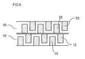
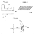
- a gap 140 the size of which is set within a range over which the extent of magnetic flux leakage remains small enough to be tolerated, may be formed between the A core 10 and the B core 20. Assuming that there is an air gap of approximately 0.4 mm between the rotor 100 and the stator unit 1, a gap of approximately 2 mm or more may be formed between the A core 10 and the B core 20 in order to limit the extent of magnetic flux leakage from the A core 10 to the B core 20 and vice versa within an allowable range.
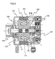
- FIG. 8 is a sectional view of the vehicle alternator taken over a side surface thereof
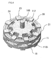
- FIG. 9 is a perspective of the rotor in the vehicle alternator
- FIG. 10 is a perspective of the vehicle alternator in a partial sectional view
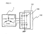
- FIG. 11 is a circuit diagram pertinent to the vehicle alternator.
- the stator unit 1 is enclosed between a front-side housing 212 shown on the left side in FIG. 8 and the rear-side housing 222 shown on the right side in the figure.
- the stator unit 1 includes the A core 10 and the B core 20 disposed side-by-side along the rotary shaft.
- a Ludell-type rotor 100 is rotatably disposed further inward relative to the stator unit 1 with a clearance formed between the stator unit and the rotor 100.
- the shaft is rotatably held via bearings disposed at the front-side housing 212 and the rear-side housing 222.
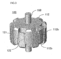
- the Ludell-type rotor 100 shown in FIG. 9 fixed to the shaft, rotates together with the rotary shaft 108.
- the Ludell-type rotor 100 includes a set of claw pole portions 112b each extending from the front side toward the rear side and another set of claw pole portions 112b each extending from the rear side to the front side. Further inward relative to the first set of claw pole portions 112a and the second set of claw pole portions 112b, a field coil 131 that generates a magnetic flux based upon a field current supplied thereto is disposed.
- a pulley disposed at the rotary shaft 108 is caused to rotate with the rotational force transmitted from an internal combustion engine installed in the vehicle via a motive power transmission belt.
- the rotation of the pulley then causes the Ludell-type rotor 100 to rotate, thereby inducing AC power at the stator unit 1.
- the AC power undergoes full wave rectification at a rectifier circuit 151 constituted with diodes 150, such as that shown in FIG. 11 .
- the DC current output from a terminal 242 as a result charges a storage battery 152 installed in the vehicle.
- Two fans 232 fixed to the rotary shaft 108 on the two sides of the Ludell-type rotor 100, are used to cool the inside of the vehicle alternator. As the rotary shaft 108 rotates, air is drawn in through vents 238 formed at the front-side housing 212 and the rear-side housing 222 and then discharged through the vents.
- the width C measured along the circumferential direction at the claw front end is set as small as possible.
- the small width assumed at the front end of the rotor claw pole reduces the extent to which the front end of the claw pole is lifted by the centrifugal force, which, in turn, allows the stator unit 1 and the Ludell-type rotor 100 to be disposed with a smaller distanced from each other. With the distance between the stator unit and the rotor reduced, better efficiency is achieved.
- the embodiment requires only two stages of stator cores each assuming a claw pole structure. In other words, it requires one fewer part compared to that required in the three stage structure in the related art and thus, the structure achieved in the embodiment canbe manufactured at a relatively low cost. Since it requires a smaller number of parts, the stator unit can be provided as a more compact apparatus. Furthermore, substantially equal inductances can be generated and thus substantially uniform current generation characteristics can be achieved at all the phases simply by winding the coils in a simple ring shape.
- N AU , N AV , and N AW representing the numbers of coil turns at the U, V and W coils at the A core 10 and the N BU , N BV , and N BW representing the numbers of coil turns of the U, V and W coils at the B core 20 may be expressed as below.
- N AU Ncos ⁇ U
- N BU Nsin ⁇ U
- N AV Ncos ⁇ V
- N BV Nsin ⁇ V
- N AW Ncos ⁇ W
- N BW Nsin ⁇ W
- ⁇ ⁇ /2 + 2nn (n: integer) corresponds to a forward rotation
- the present invention may be adopted in multiple phase coils assuming four or more different phases, as well as in conjunction with three phase coils.
- ⁇ A , and ⁇ B represent magnetic fluxes interlinking with single turn coils inside the A core 10 and the B core 20 respectively.
- the numbers of coil turns N A1 , N A2 , ... N AM and the numbers of coils N B1 , N B2 , ... N BM are determined so that the electrical phases of the magnetic flux linkages decrease in sequence by 2 ⁇ /M at a time starting at ⁇ 1 .
- the embodiment is described by assuming that the magnetic fluxes ⁇ A and ⁇ B manifest a phase difference relative to each other by 90°.
- N A1 , N B1 , N Ak , N Bk , N AM , and N BM can be written as in (24), (25) and (26) below.
- N A ⁇ 1 Ncos ⁇
- N B ⁇ 1 Nsin ⁇
- N Ak Ncos ⁇ - k - 1 ⁇ M
- N Bk Nsin ⁇ - k - 1 ⁇ M
- N AM Ncos ⁇ - M - 1 ⁇ M
- N BM Nsin ⁇ - M - 1 ⁇ M
- ⁇ represents a parameter that determines the degree of freedom with which the distribution ratios of the number of turns of the U, V and W coils at the A core 10 and the B core 20 are adjusted.
- the self inductances of single turn coils at the A core 10 and the B core 20 have the identical L.
- the individual coils at the A core 10 and the B core 20 are connected in series. Accordingly, the self-inductance L k at each coil is expressed as in (30) below.
- L k L ⁇ N Ak 2 + N Bk 2
- a six-phase coil system in particular, may be regarded as being constituted with two three-phase coil systems. Accordingly, by combining the electric currents generated via the two three-phase coil systems, an electric current with a lesser extent of ripple can be obtained. Since the ripple in the generated electric current causes noise in the generator, a quieter generator can be achieved by adopting the present invention in the six-phase coil system.
- FIGS. 12A ⁇ 12B illustrate another embodiment of the present invention. Apart from the features described below, the embodiment is similar to the first embodiment.
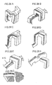
- FIG. 12A shows one of the iron sheet blank 201 used to constitute a laminated core block, which, in turn, is used to form a claw pole 212.
- the width of the claw smallest at the front end, gradually increases toward the base along the axial direction and the claw achieves an R-shape at the base, since the sectional area at the base must be set greater than the sectional area at the front end to accommodate the magnetic flux flowing in from the rotor side of the claw pole 212 and traveling toward the base.
- FIG. 12B shows an assembly formed by layering a plurality of blanks, one of which is shown in FIG.
- FIG. 12A shows the shapes of the blanks laminated one on top of the other.
- FIG. 12C shows the shape achieved by deforming the laminated blank assembly in FIG. 12B .
- the laminated assembly is deformed through plastic deformation such as bending by restraining the inner side along the radial direction, which subsequently forms the claw portion and the outer side along the radial direction, which subsequently forms the yoke portion.
- FIG. 12D presents a view of the laminated assembly 122 in FIG. 12C , taken along the direction perpendicular to the banded (layer edges) surface.
- the claw portion 210a and the yoke portion 210b each have a rectangular section and the area connecting the claw portion and the yoke portion is deformed through bending or the like.
- FIG. 12E is a view of the claw pole formed by using two laminated assemblies shown in FIG. 12C and FIG. 12D having been prepared through a bending process are coupled together at their claw portions12a.
- the two laminated assemblies are set symmetrically along the circumferential direction so as to abut the banded surfaces of the claw portions 12a with each other.
- FIG. 12F is a view of the laminated assembly in FIG. 12E taken along the direction perpendicular to the banded surfaces.
- the laminated assembly in the figure is obviously constituted of two laminated assemblies in FIG. 12D set symmetrically by using an area of the claw portion 210 as the plane of symmetry.
- the laminated assembly in FIG. 12F constitutes a single claw portion.
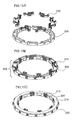
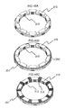
- FIGS. 13A through 13C illustrate a single stage stator formed by using claw poles, one of which is shown in FIGS. 12A through 12F .
- FIG. 13A shows eight laminated assemblies, each used to form the claw pole 212 as described in reference to FIGS. 12A through 12F , disposed along the circumferential direction.
- a holding plate 204 grooves are formed so as to position and hold the laminated assemblies accurately.
- the laminated claw poles 212 are set into the grooves, they are positioned correctly, thereby forming a half stage stator 203 constituting one half of a stage stator, as shown in FIG. 13B .
- FIG. 13C ring-shaped windings can be disposed at a full stage stator 207.
- a full stator for a given stage is formed by disposing a half stage stator 203, such as that shown in FIG. 13C and a half stage stator without any stator coil 14 (or any stator coil 24) disposed therein, such as that shown in FIG. 13B so that they face opposite each other along the axial direction.
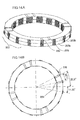
- FIGS. 14A and 14B present external views of the full stage stator 207.
- Holding plates 204 hold the laminated assemblies constituting the claw poles 212 between them. This means that the mechanical strength of the stator is determined by the strength of the holding plates.
- FIG. 14A shows a surface of a holding plate present along the axial direction, the structure assumed at the surface is now described.
- Sets made up of a positioning groove 206 and a positioning projection 205 having a predetermined positional relationship relative to each other are formed at least at three positions along the circumferential direction at the surface facing along the axial direction of the holding plate 204.
- FIG. 14B illustrates this positional relationship. The positional relationship shown in the figure is assumed in the 16-pole, two-stage three-phase motor achieved in the embodiment.
- the individual stage stators are disposed with an offset of 90° electrical angle (11.25° mechanical angle) relative to each other along the circumferential direction.
- the groove and the corresponding projection are set at positions with an offset of 11.25° relative to each other along the circumferential direction.
- a half stage stator 203a and another half stage stator 203b are connected along the axial direction, their positions must be taken into consideration.
- the positional relationship of the projection 205 and the groove 206 on the upper side to those on the lower side is reversed at a position forming an angle of 11.25° from the center of a claw pole, i.e., relative to a position equivalent to a quarter of the full cycle in the electrical angle and, accordingly, the positioning groove 206 is formed at a position forming an 11.25° angle relative to the center of the clawpole and the corresponding projection is formed with an offset of 11.25° relative to the positioning groove.
- Projection/groove pairs, each made up with the projection and the groove are disposed over equal intervals of 90°, so as to enable accurate positioning along the circumferential direction.
- FIG. 15 shows the structure of a given holding plate 204 in a sectional view.
- the holding plate 204 includes guide portions used to hold the stator coil 14 (or the stator coil 24; the same principle applies hereafter). Namely, since the stator coil 14 must be disposed without contacting the core 12, the stator coil 14 is held over a distance so as to form a clearance between the core 12 and the stator coil 14.
- the holding plate assumes a thickness measured along the axial direction which is greater than the thickness of the core blocks and includes a surface ranging along the circumferential direction with a diameter greater than the inner circumferential side measurement of the claw portions, but smaller than the inner diameter of the yoke portion so as to accommodate the installation of the stator coil 14.
- the stator coil 14 is exclusively positioned and held without contacting the core.
- FIG. 16 presents an example that may be adopted when assembling the stators corresponding to the two stages.
- the positional relationship between the stage stators is exclusively determined as the grooves and the projections formed at the holding plates 204 along the axial direction are interlocked.
- the positioning projections 205 and the positioning grooves 206 formed at the upper surface of the stage stator (A core 10) in FIG. 16 are made to fit with the positioning projections 205 and the positioning grooves 206 formed at the lower surface of a stator corresponding to another stage (B core 20).
- the inner circumferential surface and the outer circumferential surface of the stator unit in the rotating electrical machine to be used as a motor or a dynamo electric generator may be machined so as to provide an optimal stator unit.
- the inner circumferential surface and the outer circumferential surface are machined so as to achieve a high level of circularity by using a machining tool such as a lathe.
- the inner circumferential surface and the outer circumferential surface in the assembled state both initially assume an angular contour forming a polygonal shape along the circumferential direction formed by the end surfaces of the laminated assemblies.
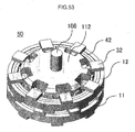
- FIG. 17 shows the components to be assembled into a motor representing an example of the rotating electrical machine according to the present invention.
- a ring-shaped permanent magnet 220 is disposed at the rotor that includes bearings 219a and 219b and the two-stage three-phase stator unit 1 (not shown) is disposed so as to surround the stator.
- An output-side end bracket 211 and a rear-side end bracket 214 are disposed as shown in the figure so as to hold the stator unit and the rotor between them and the entire assembly is fastened together along the axial direction with through bolts 216.
- a complete motor 221 is produced. Since no coil ends are present along the axial direction, a lower profile is achieved along the axial direction and thus, the motor is provided as a compact unit.
- FIGS. 18A through 18C present examples of structures that may be adopted for the holding plates.
- FIG. 18A shows one of the holding plates described in reference to the previous embodiment. It includes grooves at which laminated core blocks are held. It also includes inner circumferential side walls and outer circumferential side walls with which the coil is exclusively positioned and held.
- such holding plates must be constituted of a nonmagnetic material.
- the material must assure a certain level of strength in order to firmly hold the laminated core blocks. For this reason, it is desirable to form the holding plates with a nonmagnetic metal or an organic material such as resin.
- the resin materials that may be used to form the holding plates include LCP (liquid crystal polymer), PPS (polyphenylene sulfide resin), PBT (polybutylene terephthalate resin), PET (polyethylene resin), nylon reinforced with glass fiber and PC (polycarbonate resin).
- LCP liquid crystal polymer
- PPS polyphenylene sulfide resin
- PBT polybutylene terephthalate resin
- PET polyethylene resin
- nylon reinforced with glass fiber and PC polycarbonate resin
- Carbon fiber-reinforced resins and thermosetting resins such as epoxy resin and unsaturated polyester resin, too, are options that may be considered. It is desirable to select the optimal material in conformance to specific conditions set based upon the thermal and mechanical strength requirements of the particular motor or generator.
- the holding plates may be manufactured by using aluminum or copper alloy through die casting, whereas they may be manufactured by using a stainless steel alloy through machining or cold or warm casting.
- the holding plates may be manufactured by using a resin material through injectionmolding or the like.
- FIG. 18B shows a holding plate assuming the shape of a plate. The holding plate assuming this shape can be manufactured with ease through machining such as casting or press molding by using ring-shaped blanks or the like.
- FIG. 18C shows a holding plate that includes an outer circumferential wall that holds in the laminated assemblies. Since no laminated core blocks range beyond the wall in the assembled state, the holding plate may also function as part of a housing.
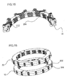
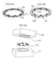
- FIGS. 19A ⁇ 19C Another embodiment of the present invention is described in reference to FIGS. 19A ⁇ 19C .
- the embodiment is identical to the first embodiment described above except for the specific features explained below.
- FIGS. 19A ?? 19C each show a half stage stator 3 corresponding to a given stage.
- the structure of the half stage stator shown in FIG. 19A is similar to that shown in FIG. 13B .
- FIG. 19B shows a structure with a thin holding plate portion 230b covering the coil installation surfaces of the stator core blocks.
- FIG. 19C illustrates how a stator core assuming such a structure may be formed.
- FIG. 19C schematically illustrates a die unit.
- a lower die 231 to be used as a base includes a holding portion with which the laminated core blocks to constitute the claw poles on one side can be accurately positioned along the circumferential direction.
- the required number of claw poles (eight claw poles are disposed along the circumferential direction in this embodiment) are disposed along the circumferential direction and the claw poles set in place are clamped by using an upper die 232 that includes a gate (resin intake port) 233 formed thereat.
- the space formed inside the upper and lower die assumes a shape matching the shape of the holding plate, and the laminated core blocks to constitute the claw poles 212 are set at specific positions in the space assuming a shape identical to that of the holding plate.
- molten metal should be poured through the intake port so as to form a half stage stator 203 with its holding plate portion constituted of metal through die casting.
- Thematerial thatmaybeused in the die casting process may be an aluminum alloy, a zinc alloy or a copper alloy.
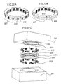
- FIGS. 20A ⁇ 20C Another embodiment of the present invention is described in reference to FIGS. 20A ⁇ 20C .
- the embodiment is identical to the first embodiment described above except for the specific features explained below.
- FIGS. 20A ⁇ 20C each show a stage stator similar to that shown in FIG. 14A .
- FIG. 20A shows a structure similar to that shown in FIGS. 14A and 14B .
- a holding plate portion 330 is present around the laminated core blocks in the structure shown in FIG. 20B as in the structure shown in FIG. 20A
- the holding plate portion 330 in FIG. 32B covers the outer circumferential-side surface of the stator.
- the laminated core blocks are assembled on a holding plate prepared in advance as a separate component in order to achieve the target shape, an integrated stator is obtained by using injection molding dies in the embodiment, as in the fifth embodiment.
- FIG. 20C schematically illustrates how such an integrated stator may be manufactured.
- a lower die 231 used as the base includes a holding portion with which the laminated core blocks to constitute the claw poles on one side can be positioned accurately along the circumferential direction.
- the necessary number of claw poles 212 (eight claw poles are disposed along the circumferential direction in the embodiment) are disposed along the circumferential direction
- a ring-shaped stator coil 14 (stator coil 24) is disposed atop the surfaces of the claw poles ranging axially via an insulating sheet 235 constituted of a thin insulating film, and the core blocks to constitute the claw poles 212 to assume the opposite polarity are positioned and assembled via an insulating sheet 235.
- an upper die 232 that includes a gate (resin intake port) formed thereat.
- the space formed inside the upper and lower dies assumes a shape matching the shape of the holding plate, and the components such as the laminated core blocks to constitute the claw poles 212 and the coil are set at specific positions in the space assuming a shape identical to that of the holding plate 4.
- a resin is poured through the intake port so as to form a single stage stator 207 as an integrated unit that includes as an integrated part thereof a holding plate portion 230 constituted of resin.
- the laminated core blocks and the coil are locked onto the holding plate portion 230 without any gap formed between them, assuring improved strength, thereby allowing the stator to better withstand vibrations and the like.
- the positional accuracy improves as well.
- the metal die casting materials cannot be utilized in the method in the embodiment, since the insulating film on the coil, which is cast together as an integrated part, would become damaged by the heat during the forming process.
- the method achieved in the embodiment may be adopted in conjunction with resin materials such as LCP (liquid crystal polymer), PPS (polyphenylene sulfide resin), PBT (polybutylene terephthalate resin), PET (polyethylene resin), nylon reinforced with glass fiber and PC (polycarbonate resin).
- resin materials such as LCP (liquid crystal polymer), PPS (polyphenylene sulfide resin), PBT (polybutylene terephthalate resin), PET (polyethylene resin), nylon reinforced with glass fiber and PC (polycarbonate resin).
- CFRP liquid crystal polymer
- PPS polyphenylene sulfide resin
- PBT polybutylene terephthalate resin
- PET polyethylene resin
- nylon reinforced with glass fiber and PC polycarbonate resin
- Carbon fiber-reinforced resins and thermosetting resins such as epoxy resin and unsaturated polyester resin are also options that may be considered. It is desirable to select the optimal material by factoring the specific conditions set based upon the thermal and mechanical strength requirements of
- the claw poles at a claw pole motor normally assume a crested shape tapering toward the claw front end.
- a shape maybe formed by punching individual metal sheets or individual groups of sheets in different shapes and stacking them one on top of another.
- FIG. 21 shows a claw pole formed through such a method. Blanks such as that shown in FIG. 12A are obtained through punching by adjusting the height over the area to form the claw pole in correspondence to each blank, and then the blanks are laminated to form a laminated core block so as to achieve the shape shown in the figure.
- the taper angle at the claw is determined in relation to the number of poles.
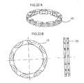
- FIGS. 22A and 22B illustrate an embodiment achieved by adjusting the relationship among the holding plate, the laminated core blocks and the coil.
- the embodiment is similar to the previous embodiments except for the specific features detailed below.
- FIG. 22A is a perspective of a winding bobbin 213, which functions as a holding plate to hold the coil.
- FIG. 22B presents a front view and a side elevation of the bobbin shown in FIG. 22A .
- the winding bobbin 213 includes grooves at which the laminated core blocks are held, as is clearly indicated in the front view.
- the grooves used to hold the laminated core blocks are formed both at the front surface and at the rear surface of the winding bobbin.
- the grooves formed at the front surface to hold the laminated core blocks and the grooves formed at the rear surface to hold the laminated core blocks are offset relative to each other by a predetermined angle along the circumferential direction.
- the bobbin also includes grooves through which a ring-shaped winding is wound, as shown in the side elevation and the perspective.
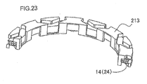
- FIG. 23 shows the winding bobbin 213 in a sectional view, so as to better show the ring-shaped stator coil 14 (24) wound around the bobbin. Inside the bobbin, the ring-shaped stator coil formed by winding a conductor with a round section is installed.
- FIG. 24A shows how the bobbin is combined with the laminated core blocks. The laminated core blocks are each set in the holding groove formed at the winding bobbin 213 and, as a result, the individual laminated core blocks are held securely along the circumference.
- FIG. 24B shows the assembled unit. Theassembled unit ultimately obtained as described above is a single stage stator similar to that shown in FIG. 14D. By adopting the embodiment, the winding can be held with ease and the coil can also be insulated from the stator core with ease.
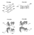
- FIGS. 25A through 25C present an example of a structure that may be adopted in order to obtain laminated core blocks with ease.
- FIG. 25A shows one of the blanks to be used to form a core, similar to that shown in FIG. 12A . Over a central area of the blank, a half blank groove 236a/projection 236b, to be used for purposes of caulking, is formed.
- FIG. 25B shows an assembly formed by laminating such blanks with an offset. The presence of the groove /projection in FIG. 25A allows blanks to be layered even when they need to be slightly offset relative to each other. In other words, laminated core blocks such as that shown in FIG. 25B with the individual blanks fixed firmly one over another, can be obtained with ease through caulking.
- FIG. 25A shows one of the blanks to be used to form a core, similar to that shown in FIG. 12A . Over a central area of the blank, a half blank groove 236a/projection 236b, to be used for purposes
- FIG. 25C illustrates a specific position at which a laminated core block is installed along the circumferential direction in a view taken along the axial direction.
- the claw pole the shape of which is indicated by the parallelograms in the figure, is identical in shape to that in FIG. 25B .
- the claw pole in the embodiment can be formed without the bending process shown in FIG. 12A ⁇ 12F in order to achieve the shape shown in FIG. 12C .
- the claw poles in the embodiment can be formed with ease by using laminated core blocks formed as shown in FIG. 25B .
- FIG. 26A in which the laminated blank assembly is bent at a right angle at one position instead of two positions.
- FIG. 26D which is a variation of FIG. 26C
- the claw portion of the claw pole is constituted with an unbent laminated assembly.
- a circumferential portion to constitute the yoke is formed separately from the claw portion.
- FIGS. 26F and 26G each illustrate a structure in which the eddy current loss occurring as the magnetic flux originating from the claw portion flows into the ring portion is reduced by altering the layering direction along which the blanks are laminated at the ring portion in FIG.
- FIGS. 27A through 27C each show a method whereby laminated core blocks are fixed together through welding.
- the portion of the laminated core block where the coil is to be held is welded over the trunk area.
- Magnetic fluxes originating from the rotor in a claw pole motor equipped with the claw poles in the embodiment flow in through the claw pole surfaces and, for this reason, welding the laminated assemblies may result in an increase in the extent of loss such as the eddy current loss.
- FIGS. 28A through 28C each present an example in which the laminated core block is fastened through caulking.
- a V caulk is formed at the center of the core trunk.
- FIG. 28B presents an example in which a caulk is formed at the front end of the claw pole in order to reduce vibration and noise, based upon a rationale similar to that of the example presented in FIG. 27B . While there may be a concern that this structure may lead to a slight increase in the occurrence of eddy currents, countermeasures such as those shown in FIG. 28C against eddy currents may be taken to reduce eddy currents, e.g., by caulking every other blank over the trunk area.
- FIGS. 29A and 29B illustrate a method that may be adopted when connecting caulks at every other blank.
- FIG. 29A is a perspective illustrating the principle of the method. Blanks, each having a groove 236a and a projection 236b formed therein at specific positions, are disposed so that the grooves 36a and the projections 36b are set alternately to each other along the layering direction to allow a projection to be fitted in a groove at each connecting area.
- FIG. 29B shows the caulking areas in a sectional view. The blanks are alternately connected through the caulking portions on the left-hand side in the figure and through the caulking portions on the right-hand side in the figure in a reiterated pattern so that every other blank in the laminated assembly is connected on the same side.
- FIGS. 31A and 31B another embodiment of the present invention is described.
- the embodiment is similar to the previous embodiments except for the specific features detailed below.
- the radius R1 of the inner surface of the laminated core block formed with blanks assuming a specific shape is set equal to or less than the radius R2 of the section of the ring-shaped stator coil 14 (24).
- the structure shown in FIG. 31A minimizes the gap formed between the stator core and the ring-shaped stator coil 14 (24) so as to improve the space factor required for installation of the coil.
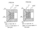
- FIGS. 32A through 32C and 33A through 33C another embodiment of the present invention is described.
- the embodiment is similar to the previous embodiments except for the specific features detailed below.
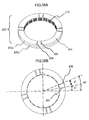
- FIG. 32A is a perspective of a rotor achieved in the embodiment.
- FIGS. 32B and 32C each illustrate a specific shape that may be adopted in grooves formed at a rotor claw pole in a sectional view taken along the axial direction.
- FIG. 33A shows the rotor claw pole in a sectional view taken along the axial direction.
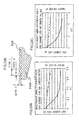
- FIG. 33B presents a graph indicating the relationship of the groove pitch/width ratio to the eddy current loss and the induced voltage.
- FIG. 33C presents a graph indicating the relationship of the groove depth/width ratio to the eddy current loss and the induced voltage. It is to be noted that the same terms and reference numerals are assigned components identical to those in the other embodiments.
- eddy currents also occur at rotor claw poles 242. Since the claws at the rotor are constituted of a magnetic metal such as iron, eddy currents flow by circling around the outer surfaces of the rotor claw poles 242.
- a plurality of grooves 245 extending along the circumferential direction are formed with substantially equal intervals along the axial direction at the outer surface of each rotor claw pole 242, as shown in FIG. 32A .
- the presence of the plurality of grooves 245 formed at the outer surface of the rotor claw pole 242, as described above, increases the electrical resistance, which, in turn, inhibits flows of eddy currents.
- FIGS. 30B and 30C show rotor claw poles 42b with beveled areas 42b-7 formed therein.
- the width Bi of the beveled area located on the side along the direction opposite from the rotating direction, i.e., on the side where the base portion assumes a greater width is set greater than the width Bd of the beveled area located on the side along the direction in which the rotor rotates at rotor claw pole 42.
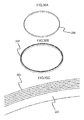
- a yoke portion 251 formed in a ring shape is disposed in the gap created between the laminated core blocks forming the two poles along the axial direction.
- the ring-shaped yoke portion 251 is formed by layering metal sheets along the radial direction.
- a stator coil 14 (24) formed by winding a multiple times a ring-shaped conductor is disposed.
- Each stage stator in the rotating electrical machine is configured by forming a plurality (ten magnetic claw pole pairs in this example) of pole pairs, each pair made up with a claw pole 212a formed with a laminated core block and a claw pole 212b formed with a laminated core circuit and assuming the opposite polarity, along the circumferences of the coil 20 and the ring-shaped yoke portion 251.
- a plurality of such stage stators two stators in the first embodiment described earlier
- a two-stage three-phase rotating electrical machine is formed.
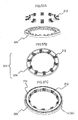
- FIGS. 38A and 38B present external views of the full stage stator 207.
- the laminated assemblies constituting the claw poles 212 are held between holding plates 204.
- the mechanical strength of the stator is thus determined in correspondence to the strength of the holding plates.
- the structure of the holding plates assumed at their surfaces ranging along the axial direction as shown in FIG. 38A is now described.
- a set of positioning grooves 206 and a positioning projection 205 formed with a predetermined positional relationship relative to each other is present at least at three positions along the circumferential direction at the surface of each holding plate 204 ranging along the axial direction.
- FIG. 38B illustrates this positional relationship.
- the positional relationship shown in the figure is adopted in a 20-pole two-stage three-phase motor achieved in the embodiment.
- the holding plates 204 are formed so as to assume a greater thickness along the axial direction than the core blocks and assume a smaller measurement along the circumferential direction than the inner diameter of the stator coil 14 (24). Via this guide portion, the stator coil 14 (24) is exclusively positioned between the yoke portion 251 and the guide portion.
- the inner circumferential surface and the outer circumferential surface are machined so as to achieve a high level of circularity by using a machining tool such as a lathe.
- the inner circumferential surface and the outer circumferential surface in the assembled state both assume an angular contour forming a polygonal shape along the circumference due to the presence of the end surfaces of the laminated assemblies. For this reason, when the rotor with a round section is disposed on the inner circumferential side, non-uniform gaps may be formed and, in such a case, the rotating electrical machine may fail to achieve a satisfactory magnetic flux distribution. Accordingly, by machining the inner circumference through trimming or grinding, better characteristics can be assured.
- the rotating electrical machine may be utilized without first machining the inner circumference, as long as the desired characteristics are already assured.
- the rotating electrical machine may be assembled by ensuring that the claw poles are disposed so as to achieve a smooth, round contour along the circumferential direction.
- the inner circumferential surface may be machined to achieve a diameter of, for instance, 0100 mm ⁇ 0.01 mm.
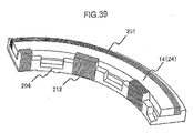
- FIG. 41 shows a structure that may be adopted in the holding plates 204.
- the holding plates each include grooves at which the laminated core blocks are held and an outer side wall via which the ring-shaped yoke portion 251 is exclusively positioned and held.
- the stator coil 14 (24) is held via the outer side wall and the yoke portion 251.
- Such holding plates 204 may be manufactured by using any of the materials listed in reference to the holding plates 204 in the previous embodiments.
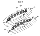
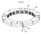
- FIGS. 42 and 43 an embodiment achieved by forming lead grooves via which the ends of the coils 2 are led out at the holding plate 204 shown in FIG. 41 is described.
- the embodiment is identical to the 15 th embodiment except for the particular features described below.
- the leader wires of the individual coils need to be led out from the stators, in order to output the electric currents flowing through the stator coils 14 (24) corresponding to the U-phase, the V-phase and the W-phase to the rectifier circuit 115 such as that shown in FIG. 11 .
- the present invention is adopted in a motor, connectors used to connect the coils to the U, V and W arms at the inverter are equivalent to the leader wires.
- lead grooves 291, through which the stator coils 14 (24) are led out are formed at the holding plates 204 so as to draw out leader wires 292 of the stator coils 14 (24) from the holding plates 204 via the lead grooves, as shown in FIGS. 42 and 43 .
- the lead grooves 291 should each be formed between a claw pole and another claw pole.
- the lead grooves 291 may be formed in a quantity other than that shown in the figure.
- the number of lead grooves may match the number of leader wires 292 required in the generator.
- the lead grooves 291 may be each constituted with a hole or a clearance instead of a groove.
- the bobbin also includes grooves through which a ring-shaped winding is disposed.
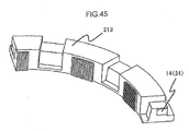
- FIG. 45 shows the winding bobbin 213 in a sectional view, so as to better show the stator coil 14 (24) wound around the winding bobbin 213.
- the ring-shaped coil is installed.
- FIG. 46A illustrates how the laminated core blocks are assembled in conjunction with the bobbin. Via the winding bobbin 213, the laminated core blocks can be held so as to form a circle within the groove in which the laminated core blocks are held.
- FIG. 46B illustrates how the bobbin and the laminated core blocks are then combined with the ring-shaped yoke portion. The figure clearly indicates that the yoke portion can be disposed on the outer circumferential side of the winding bobbin 213.
- FIG. 46C shows the assembled stator, which is a stage stator similar to that shown in FIG. 38A .
- the claw poles at a claw pole motor normally assume a crested shape tapering toward the claw front ends.
- Such a shape may be formed by punching individual metal sheets or individual groups of metal sheets in different shapes and layering them one on top of another.
- FIG. 47 shows a claw pole formed through such a method. Blanks such as that shown in FIG. 35A are obtained through punching by adjusting the height of the area to form the claw pole in correspondence to each blank, and then the blanks are layered to form a laminated core block so as to achieve the shape illustrated in the figure.
- the taper angle of the claw is determined in relation to the number of poles.
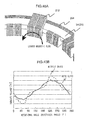
- FIGS. 48A and 48B a structure that may be adopted in the laminated core blocks to improve the motor efficiency by reducing the extent of distortion of the induced voltage is described.
- the embodiment is similar to the 15 th embodiment except for the specific features detailed below.
- the motor output torque is in proportion to the level of induced voltage
- a distortion of the induced voltage causes pulsation in the motor output torque, which, in turn, causes motor vibration and noise.
- the induced voltage should assume a waveform as close as possible to a sine wave.
- One of the primary causes of induced voltage distortion is magnetic flux leakage.
- the magnetic flux leakage shown in FIG. 48A does not interlink with the coil and thus does not contribute in any way whatsoever to the motor characteristics. It simply induces magnetic saturation at the core, which leads to distortion of the induced voltage.
- the leaked magnetic flux flowing along the direction in which the metal sheets are layered to form the laminated core blocks induces an eddy current inside the laminated core to lower the motor efficiency.
- FIG. 48A The structure assumed for the laminated core blocks shown in FIG. 48A reduces such magnetic flux leakage.
- two laminated core blocks form a single pole. Namely, a slit is formed at a halfway position along the circumferential direction at a claw pole.
- the magnetic resistance in the magnetic path of the leaked magnetic flux is increased via the slit, thereby reducing the magnetic flux leakage.
- the extent of magnetic saturation at the core attributable to leaked magnetic flux is lessened, which, in turn, reduces the extent of distortion of the induced voltage.
- FIG. 48B presents examples of the voltage waveforms of voltages induced at claw poles with/without slits formed at the halfway positions. The graph presented in FIG. 48B indicates that the presence of the slits reduces the extent of distortion of the induced voltage. Furthermore, since the eddy current loss attributable to magnetic flux leakage is reduced, the motor efficiency is improved.
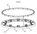
- FIG. 49 shows a structure that may be adopted in conjunction with the 19 th embodiment in order to manufacture a large unit with a high level of productivity.
- FIG. 49 shows two laminated core blocks forming a single pole.
- the yoke portion 251 is split into a plurality of separate blocks along the circumferential direction.
- the yoke portion 251 is separated into a plurality of blocks at halfway positions of the individual poles. Namely, a magnetic flux originating from the rotor and flowing in through a claw pole flows to the yoke portion blocks 251 on the left side and the right side thereof and then flows out toward the rotor through the claw poles 212 present next to the entry pole along the circumferential direction.
- an outer circumferential wall 258 of the holding plate 4 exclusively determines the positions of the split yoke portion blocks 251 along the radial direction, whereas a plurality of projections 259 formed along the circumferential direction exclusively determines the positions of the split yoke portion blocks 251 along the circumferential direction.
- a half stage stator 203 with the split yoke portion blocks 251 thereof positioned exclusively is obtained.
- an N-phase motor that includes an N-phase coil system with coils corresponding to the U-phase, the V-phase and the W-phase wound so as to achieve N different turn ratios is described.
- N k U , N k V and N k W respectively represent the numbers of turns at the U-phase coil, the V-phase coil and the W-phase coil in the kth coil group of the N-phase coil system.
- the numbers of coil turns may each assume a positive value, the value 0 or a negative value. When the number of coil turns assumes a negative value, the coil is wound along the reverse direction. In addition, the number of coil turns does not need to be a positive or negative integer and may assume a positive or negative non-integral value. When the number of coil turns assumes a non-integral value, the coil is wound through a hole formed at a magnetic pole so as to partially interlink the pole.
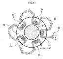
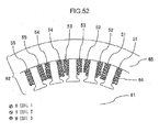
- FIG. 51 shows a five-phase motor achieved in an embodiment of the present invention, which is equipped with three phase coils, i.e., the U-, V- and W-phase coils.
- a motor 60 includes a rotor 61, a stator 62, a three-phase AC power source 63 corresponding to the U, V and W phases and a first coil group 51, a second coil group 52, a third coil group 53, a fourth coil group 54 and a fifth coil group 55 in the five-phase coil system.
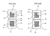
- FIG. 52 shows how the three-phase coil, i.e., the U-phase coils, the V-phase coils and the W-phase coils may be installed.
- U-phase coils 1, V-phase coils 2 and W-phase coils 3 are wound together around stator teeth 64.
- I k 5 I N k U + N k V ⁇ exp - j ⁇ 2 ⁇ ⁇ / 3 + N k W ⁇ exp j ⁇ 2 ⁇ ⁇ / 3
- I 3 5 I - 5 + 6 ⁇ exp - j ⁇ 2 ⁇
- the rotating electrical machine in the example described above includes coils wound through concentrated winding, the present invention may also be adopted equally effectively in conjunction with coils wound through distributed winding.
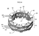
- the ring-shaped stator coil 41 is wound around the A core 10 through the areas enclosed by the core back 11 and the claw poles 21 and 31, whereas the ring-shaped stator coil 42 is wound around the B core 20 through the areas enclosed by the core back 12 and the claw poles 22 and 32.
- the coils are each held along the axial direction at the stator 62 between each claw pole and the next claw pole, which assumes the opposite polarity.
- the core backs each form the magnetic path between adjacent magnetic_poles.
- the coils include a U1 coil, a U2 coil, a V1 coil, a V2 coil, a W1 coil and a W2 coil and their leader wires are shown in the figure. These coils are to be described in detail later.
- the total numbers of coil turns each representing the sum of the numbers of coil turns for the U-phase coil, the V-phase coil and the W-phase coil in a given coil group, which are close to one another at 10.4 and 12, can be achieved in the individual the coil groups by setting N 1 V , and N 2 V respectively to -5.2 and 3 and setting N 1 W and N 2 W respectively to 5.2 and 3 at the two-stage stator.
- the number of coil turns assumes a non-integral value, the corresponding coil has the entry point and then exit point at different positions.
- I k 4 I N k U + N k V ⁇ exp - j ⁇ 2 ⁇ ⁇ / 3 + N k W ⁇ exp j ⁇ 2 ⁇ ⁇ / 3
Applications Claiming Priority (2)
| Application Number | Priority Date | Filing Date | Title |
|---|---|---|---|
| JP2007274579A JP2009106044A (ja) | 2007-10-23 | 2007-10-23 | 回転電機 |
| JP2008114764A JP2009268258A (ja) | 2008-04-25 | 2008-04-25 | 回転電機 |
Publications (1)
| Publication Number | Publication Date |
|---|---|
| EP2053721A2 true EP2053721A2 (de) | 2009-04-29 |
Family
ID=40329127
Family Applications (1)
| Application Number | Title | Priority Date | Filing Date |
|---|---|---|---|
| EP08014860A Withdrawn EP2053721A2 (de) | 2007-10-23 | 2008-08-21 | Drehmaschine |
Country Status (2)
| Country | Link |
|---|---|
| US (1) | US20090102314A1 (de) |
| EP (1) | EP2053721A2 (de) |
Cited By (4)
| Publication number | Priority date | Publication date | Assignee | Title |
|---|---|---|---|---|
| WO2014198275A1 (en) * | 2013-06-11 | 2014-12-18 | Danmarks Tekniske Universitet | A large electrically excited synchronous generator |
| TWI576026B (zh) * | 2015-07-17 | 2017-03-21 | 財團法人工業技術研究院 | 電路結構 |
| WO2017069532A1 (en) * | 2015-10-22 | 2017-04-27 | Samsung Electronics Co., Ltd. | Motor and motor control circuit |
| EP3317945A4 (de) * | 2015-10-22 | 2018-07-04 | Samsung Electronics Co., Ltd. | Motor und motorsteuerungsschaltung |
Families Citing this family (24)
| Publication number | Priority date | Publication date | Assignee | Title |
|---|---|---|---|---|
| US7649274B2 (en) * | 2006-02-09 | 2010-01-19 | Windera Power Systems, Inc. | Turbine with constant voltage and frequency output |
| JP4535190B2 (ja) * | 2008-02-07 | 2010-09-01 | 株式会社デンソー | 燃料ポンプ |
| DE102010018472A1 (de) * | 2009-07-03 | 2011-01-05 | Schaeffler Technologies Gmbh & Co. Kg | Lager mit Energieerzeugungseinheit |
| DE102009031609A1 (de) * | 2009-07-03 | 2011-01-05 | Schaeffler Technologies Gmbh & Co. Kg | Lager mit Energieerzeugungseinheit |
| US8319464B2 (en) * | 2009-08-18 | 2012-11-27 | U.S. Department Of Energy | Flux control and one-hundred and eighty degree core systems |
| JP2012245871A (ja) * | 2011-05-27 | 2012-12-13 | Tbk:Kk | 電気式暖房装置および電気自動車 |
| EP2570659B1 (de) * | 2011-09-15 | 2013-11-13 | Siemens Aktiengesellschaft | Windturbine |
| US11146123B2 (en) * | 2012-02-03 | 2021-10-12 | Green Ray Technologies, Llc | Electric machines with energizable and non-energizerable U-shaped stator segments |
| JP5666494B2 (ja) * | 2012-03-01 | 2015-02-12 | セイコープレシジョン株式会社 | アクチュエータ |
| JP5802581B2 (ja) * | 2012-03-14 | 2015-10-28 | 日立オートモティブシステムズ株式会社 | 回転電機及びその生産方法 |
| DE102013208433A1 (de) * | 2012-05-25 | 2013-11-28 | Robert Bosch Gmbh | Elektrowerkzeugmaschine |
| JP6148085B2 (ja) * | 2012-07-31 | 2017-06-14 | アスモ株式会社 | モータ、及びモータのステーコア及びロータコアの製造方法 |
| JP6017220B2 (ja) * | 2012-08-09 | 2016-10-26 | ミネベア株式会社 | クローポール型モータ |
| US9450475B2 (en) * | 2012-11-01 | 2016-09-20 | Verde Smart Motors, Inc. | Methods and apparatus for a motor |
| US9887608B2 (en) * | 2013-01-24 | 2018-02-06 | Asmo Co., Ltd. | Rotor, stator and motor |
| TWI497814B (zh) * | 2013-04-09 | 2015-08-21 | Wistron Neweb Corp | 天線旋轉機構 |
| US10141821B2 (en) | 2013-09-24 | 2018-11-27 | Denso Corporation | Motor and rotor |
| KR101597965B1 (ko) * | 2014-07-02 | 2016-02-29 | 전자부품연구원 | 복합 자속을 이용한 모터 |
| JP6222032B2 (ja) * | 2014-10-14 | 2017-11-01 | 株式会社デンソー | 回転電機 |
| US10581310B2 (en) * | 2016-09-04 | 2020-03-03 | Meghdad Rezaee | Electromechanical converter for automatically changing and adjusting driving torque in a vehicle |
| US20180083505A1 (en) * | 2016-09-19 | 2018-03-22 | Shenzhen Baici Energy Co., Ltd. | Divided Magnetic Generator |
| CN108173404B (zh) * | 2018-02-10 | 2023-08-11 | 安徽万至达电机科技有限公司 | 超声振动电机 |
| SE542749C2 (en) * | 2018-12-04 | 2020-07-07 | Sem Ab | Crankshaft driven flywheel magneto generator with circular winding for power supply in handheld batteryless combustion engines |
| CN113315270A (zh) * | 2021-06-02 | 2021-08-27 | 河北工业大学 | 一种爪极电机定子铁芯、及应用该定子铁芯的电机组件 |
Citations (2)
| Publication number | Priority date | Publication date | Assignee | Title |
|---|---|---|---|---|
| JP2007274579A (ja) | 2006-03-31 | 2007-10-18 | Oki Electric Ind Co Ltd | 映像監視システム |
| JP2008114764A (ja) | 2006-11-07 | 2008-05-22 | Mazda Motor Corp | 車両の障害物検知装置 |
Family Cites Families (2)
| Publication number | Priority date | Publication date | Assignee | Title |
|---|---|---|---|---|
| CN1835339A (zh) * | 2005-03-18 | 2006-09-20 | 日立粉末冶金株式会社 | 三相爪极型电机 |
| JP4878183B2 (ja) * | 2005-03-18 | 2012-02-15 | 株式会社日立産機システム | 多相クローポール型モータ |
-
2008
- 2008-08-21 EP EP08014860A patent/EP2053721A2/de not_active Withdrawn
- 2008-08-22 US US12/197,116 patent/US20090102314A1/en not_active Abandoned
Patent Citations (2)
| Publication number | Priority date | Publication date | Assignee | Title |
|---|---|---|---|---|
| JP2007274579A (ja) | 2006-03-31 | 2007-10-18 | Oki Electric Ind Co Ltd | 映像監視システム |
| JP2008114764A (ja) | 2006-11-07 | 2008-05-22 | Mazda Motor Corp | 車両の障害物検知装置 |
Cited By (6)
| Publication number | Priority date | Publication date | Assignee | Title |
|---|---|---|---|---|
| WO2014198275A1 (en) * | 2013-06-11 | 2014-12-18 | Danmarks Tekniske Universitet | A large electrically excited synchronous generator |
| TWI576026B (zh) * | 2015-07-17 | 2017-03-21 | 財團法人工業技術研究院 | 電路結構 |
| US10448501B2 (en) | 2015-07-17 | 2019-10-15 | Industrial Technology Research Institute | Circuit structure |
| WO2017069532A1 (en) * | 2015-10-22 | 2017-04-27 | Samsung Electronics Co., Ltd. | Motor and motor control circuit |
| EP3317945A4 (de) * | 2015-10-22 | 2018-07-04 | Samsung Electronics Co., Ltd. | Motor und motorsteuerungsschaltung |
| US10411528B2 (en) | 2015-10-22 | 2019-09-10 | Samsung Electronics Co., Ltd. | Motor and motor control circuit |
Also Published As
| Publication number | Publication date |
|---|---|
| US20090102314A1 (en) | 2009-04-23 |
Similar Documents
| Publication | Publication Date | Title |
|---|---|---|
| EP2053721A2 (de) | Drehmaschine | |
| JP6977555B2 (ja) | 回転電機 | |
| US10720820B2 (en) | Rotating electric machine and method for manufacturing the rotating electric machine | |
| US20090001843A1 (en) | Rotating electrical machine | |
| US7348706B2 (en) | Stator assembly for an electric machine and method of manufacturing the same | |
| US8319386B2 (en) | Motor | |
| JP4586717B2 (ja) | モータ | |
| US20090315424A1 (en) | Permanent magnet synchronous machine with shell magnets | |
| WO2021039736A1 (ja) | 回転電機 | |
| WO2012063684A1 (ja) | 回転電機 | |
| WO2009113215A1 (ja) | 回転電機用の固定子鉄心およびその製造方法 | |
| JP2016167907A (ja) | 回転電機および電動パワーステアリング装置 | |
| JP2020141551A (ja) | 回転電機 | |
| JPH05115141A (ja) | スロツトレスモータ | |
| JP2020137371A (ja) | 電機子及び回転電機 | |
| JP2009027904A (ja) | 回転電機 | |
| JP2020137376A (ja) | 電機子 | |
| JP2016154445A (ja) | 回転電機、およびその回転電機を備えた車両 | |
| JP2009106044A (ja) | 回転電機 | |
| JP2020137375A (ja) | 回転電機 | |
| US20220263356A1 (en) | Motor | |
| JP2015027258A (ja) | 回転電機、固定子および固定子巻線 | |
| JP2020137373A (ja) | 電機子及び回転電機 | |
| JP2019047630A (ja) | 回転電機 | |
| US20230042319A1 (en) | Electrical machine including axial flux rotor and coreless stator |
Legal Events
| Date | Code | Title | Description |
|---|---|---|---|
| PUAI | Public reference made under article 153(3) epc to a published international application that has entered the european phase |
Free format text: ORIGINAL CODE: 0009012 |
|
| 17P | Request for examination filed |
Effective date: 20090102 |
|
| AK | Designated contracting states |
Kind code of ref document: A2 Designated state(s): AT BE BG CH CY CZ DE DK EE ES FI FR GB GR HR HU IE IS IT LI LT LU LV MC MT NL NO PL PT RO SE SI SK TR |
|
| AX | Request for extension of the european patent |
Extension state: AL BA MK RS |
|
| STAA | Information on the status of an ep patent application or granted ep patent |
Free format text: STATUS: THE APPLICATION HAS BEEN WITHDRAWN |
|
| 18W | Application withdrawn |
Effective date: 20100308 |