EP2052439B1 - Elektrische steckverbindung - Google Patents
Elektrische steckverbindung Download PDFInfo
- Publication number
- EP2052439B1 EP2052439B1 EP07801630A EP07801630A EP2052439B1 EP 2052439 B1 EP2052439 B1 EP 2052439B1 EP 07801630 A EP07801630 A EP 07801630A EP 07801630 A EP07801630 A EP 07801630A EP 2052439 B1 EP2052439 B1 EP 2052439B1
- Authority
- EP
- European Patent Office
- Prior art keywords
- contact
- lug
- electrical plug
- plug connection
- connection according
- Prior art date
- Legal status (The legal status is an assumption and is not a legal conclusion. Google has not performed a legal analysis and makes no representation as to the accuracy of the status listed.)
- Not-in-force
Links
- 239000004020 conductor Substances 0.000 claims abstract description 23
- 239000011810 insulating material Substances 0.000 claims abstract description 6
- 239000000463 material Substances 0.000 claims description 4
- 230000008878 coupling Effects 0.000 abstract 2
- 238000010168 coupling process Methods 0.000 abstract 2
- 238000005859 coupling reaction Methods 0.000 abstract 2
- 230000001681 protective effect Effects 0.000 description 3
- 239000003351 stiffener Substances 0.000 description 2
- 230000037431 insertion Effects 0.000 description 1
- 238000003780 insertion Methods 0.000 description 1
- 238000000926 separation method Methods 0.000 description 1
Images

Classifications
-
- H—ELECTRICITY
- H01—ELECTRIC ELEMENTS
- H01R—ELECTRICALLY-CONDUCTIVE CONNECTIONS; STRUCTURAL ASSOCIATIONS OF A PLURALITY OF MUTUALLY-INSULATED ELECTRICAL CONNECTING ELEMENTS; COUPLING DEVICES; CURRENT COLLECTORS
- H01R4/00—Electrically-conductive connections between two or more conductive members in direct contact, i.e. touching one another; Means for effecting or maintaining such contact; Electrically-conductive connections having two or more spaced connecting locations for conductors and using contact members penetrating insulation
- H01R4/24—Connections using contact members penetrating or cutting insulation or cable strands
- H01R4/2416—Connections using contact members penetrating or cutting insulation or cable strands the contact members having insulation-cutting edges, e.g. of tuning fork type
- H01R4/242—Connections using contact members penetrating or cutting insulation or cable strands the contact members having insulation-cutting edges, e.g. of tuning fork type the contact members being plates having a single slot
- H01R4/2425—Flat plates, e.g. multi-layered flat plates
- H01R4/2429—Flat plates, e.g. multi-layered flat plates mounted in an insulating base
- H01R4/2433—Flat plates, e.g. multi-layered flat plates mounted in an insulating base one part of the base being movable to push the cable into the slot
-
- H—ELECTRICITY
- H01—ELECTRIC ELEMENTS
- H01R—ELECTRICALLY-CONDUCTIVE CONNECTIONS; STRUCTURAL ASSOCIATIONS OF A PLURALITY OF MUTUALLY-INSULATED ELECTRICAL CONNECTING ELEMENTS; COUPLING DEVICES; CURRENT COLLECTORS
- H01R4/00—Electrically-conductive connections between two or more conductive members in direct contact, i.e. touching one another; Means for effecting or maintaining such contact; Electrically-conductive connections having two or more spaced connecting locations for conductors and using contact members penetrating insulation
- H01R4/28—Clamped connections, spring connections
- H01R4/48—Clamped connections, spring connections utilising a spring, clip, or other resilient member
- H01R4/4809—Clamped connections, spring connections utilising a spring, clip, or other resilient member using a leaf spring to bias the conductor toward the busbar
- H01R4/4811—Spring details
- H01R4/4816—Spring details the spring shape preventing insertion of the conductor end when the spring is unbiased
-
- H—ELECTRICITY
- H01—ELECTRIC ELEMENTS
- H01R—ELECTRICALLY-CONDUCTIVE CONNECTIONS; STRUCTURAL ASSOCIATIONS OF A PLURALITY OF MUTUALLY-INSULATED ELECTRICAL CONNECTING ELEMENTS; COUPLING DEVICES; CURRENT COLLECTORS
- H01R4/00—Electrically-conductive connections between two or more conductive members in direct contact, i.e. touching one another; Means for effecting or maintaining such contact; Electrically-conductive connections having two or more spaced connecting locations for conductors and using contact members penetrating insulation
- H01R4/28—Clamped connections, spring connections
- H01R4/48—Clamped connections, spring connections utilising a spring, clip, or other resilient member
- H01R4/4809—Clamped connections, spring connections utilising a spring, clip, or other resilient member using a leaf spring to bias the conductor toward the busbar
- H01R4/4846—Busbar details
Definitions
- the invention relates to an electrical connector consisting of a plug with a contact carrier made of insulating material, in which at least one contact tab or a contact lug are used, which have a fastening device for a preferably surrounding an insulating jacket conductor or a contact element for a connector, and consisting of a coupler with a contact carrier made of insulating material, in which at least one contact lug or a contact tab are used, which have a contact element for a connector or a fastening device for a preferably surrounding with an insulating conductor, wherein the plug and the contact tab at least are partially plugged together with the coupler and the contact lug, according to the features of the preamble of claim 1.
- a generic electrical connector is well known and is among other things also manufactured by the applicant (see for example the document DE 4 322 790 ).
- This connector has a contact carrier on the plug and a contact carrier on the coupler, wherein the tabs have on the end facing away from the plug contact elements for a connector.
- the contact tabs each have a fastening device for connecting an electrical conductor.
- the fastening device is equipped with a nut which partially engages in openings in the contact tab and is jammed in this.
- the nut is associated with a screw, the screw having a washer which clamps the electrical conductor.
- the washer in turn has a nose, the in a recess of the contact carrier is sufficient to cause a rotation of the washer.
- it is a very expensive attachment device for the conductor, which apart from the contact tab consists of a further three parts, which also designed complicated and thus are expensive to install.
- Object of the present invention is therefore to simplify and cheapen the fastening device and thus the contact tab or the contact lug and the complete connector.
- the fastening device is designed as a clamping spring whose spring force jammed the conductor with the contact tab or the contact lug.
- the contact lug or contact lug is folded, at least in the region of the clamping spring, from metallic flat material, preferably box-shaped, with end lugs being formed, which overlap.
- the end tabs are arranged in the overlapping region at a distance from each other, so that there is a gap between them.
- a slot is incorporated in the end tabs, preferably in the flag or the tab of the contact lug or contact tab facing away from half of the end tabs, which penetrates both end tabs.
- This slot has a width which corresponds to the inner dimension of the box-shaped attachment of the contact tab or the contact lug. Since this slot extends in both end tabs to their ends, it can already be incorporated in the metallic sheet before it is folded.
- the flag or the tab which is preferably designed as a clamping strap, can already be incorporated in the metallic flat material, wherein in particular between the clamping plate and the box-shaped attachment of the contact tab laterally slots are incorporated, so that the clamping plate can be folded independently of the box-shaped attachment.
- the clamping spring is advantageously made of flat material, has a flat strip and an adjoining spring clip and a tongue, wherein the flat stiffener is inserted into the distance between the two end tabs and that until the tongue, which is executed at right angles to the flat strip , can be inserted into the slot of the two end tabs or snaps there.
- the clamping spring can be fastened to the contact lug or contact lug without additional aids or tools.
- An opening is incorporated in the tongue disposed outside the outer end tab when no force is applied to the clamping spring, the opening then being disposed within the inner end tab when a force is applied to the outer surface of the clamping spring and thus the tongue is inserted further into the slot. If an electrical conductor is then inserted into the opening when it is arranged inside the inner end flap, then the tongue and thus the opening is pushed outward by the spring force of the spring clip, so that the conductor is clamped on the inside of one end flap.
- a slot-like gap is incorporated in the opening, namely on the side of the opening facing away from the contact lug or contact lug, the gap width of which corresponds approximately to the diameter of the conductor without an insulating jacket.
- This slot-like gap serves as a stripper. Namely, in the opening, when this is arranged outside the outer tab, an electrical conductor with insulating jacket inserted and pressed the clamping spring in the direction of contact lug or contact tab, so the slit-like gap cuts into the insulating, so that it is separated after train on the head can be.
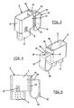
- FIGS. 1 to 5 is referred to the reference numeral 1 a plug having a contact carrier 2, which is covered by a protective cover 3.
- the contact carrier recesses 4 are provided, are used in the contact tabs 5.
- the contact tabs 5 are based on a metallic sheet, which is punched and processed accordingly and then folded.
- the contact tabs 5 have on the one hand the resilient clamping plate 6 and a box-shaped attachment 7. The clamping plate 6 and the attachment 7 are partially separated by lateral separating slots.
- a projection 8 is incorporated in the wall of the attachment 7, which establishes a positional fixation after insertion of the contact tab 5 in the contact carrier 2 in that the projection 8 engages in the designated recess 9 of the contact carrier 2.
- the contact tab 5 has after folding the attachment 7 end tabs 10, which are arranged at a distance from each other.
- a slot 11 is incorporated, which penetrates both end flaps and extends into the interior of the attachment 7.
- the slot 11 has a maximum width equal to the inner dimension of the attachment 7, so that only the end tabs 10 are cut and not the side walls of the attachment 7.
- a clamping spring 12 is inserted, with its flat strip 13 between the end tabs 10 sticks out.
- a spring clip 14 at the end of which a tongue 15 is bent approximately at right angles and projects into the slot 11 in both end flaps 10.
- the tongue 15 has an opening 16, to which a slot-like gap 17 connects.
- a flexible strip 18 is formed, which is adjacent to the clamping spring 12 when a contact tab 5 is inserted into the recess of the contact carrier 2. Is in the opening 16, which is sufficiently large to receive a conductor including the insulating jacket, this inserted and exerted on the clamping spring 12 or the bar 18, a force, the slit-like gap separates the insulating jacket from the conductor, because this in turn supported on the outer surface of the outer flap 10.
- the electrical conductor is now pulled out of the opening 16 or the slot-like gap 17, the bar 18 and thus the clamping spring 12 and the tongue 15 so far inserted into the slot 11 until the opening 16 on the inside of the inner end flap 10 is arranged. There, the conductor is then inserted into the opening 16, so that the spring clip 14 clamped after completion of the force on the bar 18 or clamping spring 12 via the tongue 15 and the opening 16 the conductor on the inner wall of the inner end flap 10.
Landscapes
- Coupling Device And Connection With Printed Circuit (AREA)
- Details Of Connecting Devices For Male And Female Coupling (AREA)
Description
- Die Erfindung bezieht sich auf eine elektrische Steckverbindung bestehend aus einem Stecker mit einem aus isolierendem Material hergestellten Kontaktträger, in dem zumindest eine Kontaktlasche oder eine Kontaktfahne eingesetzt sind, die eine Befestigungsvorrichtung für einen vorzugsweise mit einem Isoliermantel umgebenden Leiter oder ein Kontaktelement für einen Steckverbinder aufweisen, und bestehend aus einem Kuppler mit einem aus isolierendem Material hergestellten Kontaktträger, in dem zumindest eine Kontaktfahne oder eine Kontaktlasche eingesetzt sind, die ein Kontaktelement für einen Steckverbinder oder eine Befestigungsvorrichtung für einen vorzugsweise mit einem Isoliermantel umgebenden Leiter aufweisen, wobei der Stecker und die Kontaktlasche zumindest teilweise mit dem Kuppler und der Kontaktfahne zusammensteckbar sind, gemäß den Merkmalen des Oberbegriffes des Patentanspruches 1.
- Eine gattungsgemäße elektrische Steckverbindung ist allgemein bekannt und wird unter anderem auch von der Anmelderin hergestellt (siehe z.B. das Dokument
DE 4 322 790 ). Diese Steckverbindung weist einen Kontaktträger am Stecker und einen Kontaktträger am Kuppler auf, wobei die Kontaktfahnen auf dem dem Stecker abgewandten Ende Kontaktelemente für einen Steckverbinder aufweisen. In jedem Kontaktträger sind mehrere Kontaktfahnen und Kontaktlaschen untergebracht. Die Kontaktlaschen weisen je eine Befestigungsvorrichtung zum Anschließen eines elektrischen Leiters auf. Die Befestigungsvorrichtung ist mit einer Mutter ausgerüstet, die teilweise in Öffnungen in der Kontaktlasche eingreift und in diesen verklemmt ist. Der Mutter ist eine Schraube zugeordnet, wobei die Schraube eine Unterlegscheibe aufweist, die den elektrischen Leiter einklemmt. Die Unterlegscheibe ihrerseits weist eine Nase auf, die in einer Aussparung des Kontaktträgers reicht, um eine Drehsicherung der Unterlegscheibe zu bewirken.
Insgesamt handelt es sich um eine sehr aufwändige Befestigungsvorrichtung für den Leiter, die abgesehen von der Kontaktlasche aus weiteren drei Teilen besteht, die darüber hinaus kompliziert gestaltet und damit aufwändig in der Montage sind. - Aufgabe der vorliegenden Erfindung ist es daher, die Befestigungsvorrichtung und damit die Kontaktlasche oder die Kontaktfahne sowie die komplette Steckverbindung zu vereinfachen und zu verbilligen.
- Diese Aufgabe ist durch die Merkmale des Patentanspruches 1 gelöst.
- Erfindungsgemäß ist vorgesehen, dass die Befestigungsvorrichtung als Klemmfeder ausgebildet ist, deren Federkraft den Leiter mit der Kontaktlasche oder der Kontaktfahne verklemmt. Durch diese Ausgestaltung der Erfindung wird die Anzahl der Bauteile erheblich reduziert, da nunmehr nur eine Klemmfeder erforderlich ist, um den Leiter mit der Kontaktlasche oder der Kontaktfahne zu verbinden.
- In vorteilhafter Weise wird die Kontaktlasche oder Kontaktfahne zumindest im Bereich der Klemmfeder aus metallischem Flachmaterial, vorzugsweise kastenförmig, gefaltet, wobei Endlaschen angeformt sind, die sich überdecken.
- Vorzugsweise sind die Endlaschen im Überdeckungsbereich mit Abstand zueinander angeordnet, so dass sich zwischen diesen ein Spalt ergibt. Dabei ist in die Endlaschen, vorzugsweise in der der Fahne oder der Lasche der Kontaktfahne oder Kontaktlasche abgewandten Hälfte der Endlaschen ein Schlitz eingearbeitet, der beide Endlaschen durchdringt. Dieser Schlitz hat eine Breite, die der Innenabmessung des kastenförmigen Aufsatzes der Kontaktlasche oder der Kontaktfahne entspricht. Da dieser Schlitz in beiden Endlaschen bis zu deren Enden reicht, kann er bereits in dem metallischen Flachmaterial eingearbeitet werden, bevor dieses gefaltet wird. Auch die Fahne bzw. die Lasche, die vorzugsweise als Klemmlasche ausgebildet ist, kann bereits in dem metallischen Flachmaterial eingearbeitete werden, wobei insbesondere zwischen der Klemmlasche und dem kastenförmigen Aufsatz der Kontaktlasche jeweils seitlich Schlitze eingearbeitet sind, damit die Klemmlasche unabhängig von dem kastenförmigen Aufsatz entsprechend gefaltet werden kann.
- Die Klemmfeder ist in vorteilhafter Weise aus Flachmaterial hergestellt, weist einen Flachstreifen auf und einen daran anschließenden Federbügel und eine Zunge, wobei der Flachsteifen in den Abstand zwischen die beiden Endlaschen eingeschoben wird und zwar so weit, bis die Zunge, die rechtwinklig zum Flachstreifen ausgeführt ist, in den Schlitz der beiden Endlaschen eingeführt werden kann beziehungsweise dort einrastet. Dadurch kann die Klemmfeder ohne weitere Hilfsmittel oder Werkzeuge an der Kontaktlasche oder Kontaktfahne befestigt werden. In der Zunge ist eine Öffnung eingearbeitet, die außerhalb der äußeren Endlasche angeordnet ist, wenn keine Kraftausübung auf die Klemmfeder ausgeübt wird, wobei die Öffnung dann innerhalb der inneren Endlasche angeordnet ist, wenn auf die Außenfläche der Klemmfeder eine Kraft ausgeübt wird und damit die Zunge weiter in den Schlitz eingeführt wird. Wird in die Öffnung dann, wenn diese innerhalb der inneren Endlasche angeordnet ist, ein elektrischer Leiter eingesteckt, so wird durch die Federkraft des Federbügels die Zunge und damit die Öffnung nach außen geschoben, so dass der Leiter an der Innenseite der einen Endlasche eingeklemmt wird.
- In vorteilhafter Weise ist an die Öffnung, und zwar auf der Seite der Öffnung, die der Kontaktfahne oder Kontaktlasche abgewandt ist, ein schlitzartiger Spalt eingearbeitet, dessen Spaltbreite etwa dem Durchmesser des Leiters ohne Isoliermantel entspricht. Dieser schlitzartige Spalt dient als Abisolierzange. Wird nämlich in die Öffnung, wenn diese außerhalb der äußeren Lasche angeordnet ist, ein elektrischer Leiter mit Isoliermantel eingesteckt und die Klemmfeder in Richtung Kontaktahne beziehungsweise Kontaktlasche gedrückt, so schneidet der schlitzartige Spalt in den Isoliermantel ein, so dass dieser nach Zug auf den Leiter abgetrennt werden kann.
- Ein Ausführungsbeispiel einer erfindungsgemäßen Befestigungsvorrichtung, auf das die Erfindung jedoch nicht beschränkt ist und im Rahmen der konstruktiven Gegebenheiten der Steckverbindung variiert werden kann, ist im Folgenden erläutert und anhand der Figuren beschrieben.
- Es zeigen:
- Figur 1:
- einen erfindungsgemäßen Stecker in perspektivischer Darstellung mit Schnitt durch eine Schutzhaube,
- Figur 2:
- einen Schnitt durch den Stecker gemäß
Figur 1 entsprechend der Schnittlinie durch die Schutzhaube inFigur 1 , - Figur 3:
- eine perspektivische Außenansicht einer Kontaktlasche gemäß der Erfindung,
- Figur 4:
- eine Außenansicht der Kontaktlasche nach
Figur 3 mit einer um 180° verdrehten Blickrichtung und - Figur 5:
- eine Seitenansicht der Kontaktlasche.
- In den
Figuren 1 bis 5 ist mit der Beziugsziffer 1 ein Stecker bezeichnet, der einen Kontaktträger 2 aufweist, der von einer Schutzhaube 3 abgedeckt ist. In dem Kontaktträger sind Aussparungen 4 vorgesehen, in die Kontaktlaschen 5 eingesetzt werden. Es handelt sich insgesamt um vier Aussparungen, in denen vier Kontaktlaschen eingesetzt werden können. Die Kontaktlaschen 5 basieren auf einem metallischen Flachmaterial, das entsprechend gestanzt und bearbeitet und anschließend gefaltet ist. Die Kontaktlaschen 5 weisen zum einen die federnde Klemmlasche 6 und einen kastenförmigen Aufsatz 7 auf. Die Klemmlasche 6 und der Aufsatz 7 sind durch seitliche Trennschlitze teilweise voneinander getrennt. - Wie in den
Figuren 3 und 5 gezeigt ist, ist in der Wand des Aufsatzes 7 ein Vorsprung 8 eingearbeitet, der nach Einsetzen der Kontaktlasche 5 in den Kontaktträger 2 eine Lagefixierung dadurch herstellt, dass der Vorsprung 8 in die mit 9 bezeichnete Ausnehmung des Kontaktträgers 2 einrastet. Die Kontaktlasche 5 weist nach dem Falten des Aufsatzes 7 Endlaschen 10 auf, die mit Abstand zueinander angeordnet sind. In die Endlaschen 10 ist ein Schlitz 11 eingearbeitet, der beide Endlaschen durchdringt und bis in den Innenraum des Aufsatzes 7 reicht. Der Schlitz 11 hat eine Breite, die maximal dem Innenmaß des Aufsatzes 7 entspricht, so dass nur die Endlaschen 10 eingeschnitten sind und nicht die Seitenwände des Aufsatzes 7. Zwischen die Endlaschen 10 ist eine Klemmfeder 12 eingesetzt, die mit ihrem Flachstreifen 13 zwischen die Endlaschen 10 ragt. An den Flachsteifen 13 schließt sich ein Federbügel 14 an, an dessen Ende etwa rechtwinklig abgekröpft eine Zunge 15 angeformt ist, die in den Schlitz 11 in beiden Endlaschen 10 ragt. Die Zunge 15 weist eine Öffnung 16 auf, an die sich ein schlitzartiger Spalt 17 anschließt. Neben der Aussparung 4 am Kontaktträger 2 ist eine biegsame Leiste 18 angeformt, die der Klemmfeder 12 benachbart ist, wenn eine Kontaktlasche 5 in die Aussparung des Kontaktträgers 2 eingesetzt ist. Wird in die Öffnung 16, die hinreichend groß ist, um einen Leiter einschließlich des Isoliermantels aufzunehmen, dieser eingesteckt und auf die Klemmfeder 12 oder die Leiste 18 eine Kraft ausgeübt, so trennt der schlitzartige Spalt den Isoliermantel von dem Leiter ab, weil dieser seinerseits sich auf der Außenfläche der äußeren Lasche 10 abstützt. Nach Abtrennen des Isoliermantels wird nun der elektrische Leiter aus der Öffnung 16 beziehungsweise dem schlitzartigen Spalt 17 herausgezogen, die Leiste 18 und damit die Klemmfeder 12 beziehungsweise die Zunge 15 so weit in den Schlitz 11 eingeschoben, bis die Öffnung 16 auf der Innenseite der inneren Endlasche 10 angeordnet ist. Dort wird dann der Leiter in die Öffnung 16 eingesteckt, so dass der Federbügel 14 nach Beendigung der Krafteinwirkung auf die Leiste 18 oder Klemmfeder 12 über die Zunge 15 und die Öffnung 16 den Leiter an der Innenwand der inneren Endlasche 10 verklemmt. -
- 1
- Stecker
- 2
- Kontaktträger
- 3
- Schutzhaube
- 4
- Aussparung
- 5
- Kontaktlaschen
- 6
- Klemmlasche
- 7
- kastenförmiger Aufsatz
- 8
- Vorsprung
- 9
- Ausnehmung
- 10
- Endlaschen
- 11
- Schlitz
- 12
- Klemmfeder
- 13
- Flachsteifen
- 14
- Federbügel
- 15
- Zunge
- 16
- Öffnung
- 17
- schlitzartiger Spalt
- 18
- Leiste
Claims (11)
- Elektrische Steckverbindung bestehend aus einem Stecker (1) mit einem aus isolierendem Material hergestellten Kontaktträger (2), in dem zumindest eine Kontaktlasche (5) oder eine Kontaktfahne eingesetzt sind, die eine Befestigungsvorrichtung für einen vorzugsweise mit einem Isoliermantel umgebenden Leiter oder ein Kontaktelement für einen Steckverbinder aufweisen, und bestehend aus einem Kuppler mit einem aus isolierendem Material hergestelltem Kontaktträger, in dem zumindest eine Kontaktfahne oder eine Kontaktlasche eingesetzt sind, die ein Kontaktelement für einen Steckverbinder oder eine Befestigungsvorrichtung für einen vorzugsweise mit einem Isoliermantel umgebenden Leiter aufweisen, wobei der Stecker (1) und die Kontaktlasche (5) zumindest teilweise mit dem Kuppler und der Kontaktfahne zusammensteckbar sind, dadurch gekennzeichnet, dass die Befestigungsvorrichtung als Klemmfeder (12) ausgebildet ist, deren Federkraft den Leiter mit der Kontaktlasche (5) oder der Kontaktfahne verklemmt.
- Elektrische Steckverbindung nach Anspruch 1, dadurch gekennzeichnet, dass die Kontaktlasche (5) oder die Kontaktfahne zumindest im Bereich der Klemmfeder (12) aus metallischem Flachmaterial, vorzugsweise kastenförmig (Aufsatz 7) gefaltet ist und dass Endlaschen (10) angeformt sind, die sich überdecken.
- Elektrische Steckverbindung nach einem der Ansprüche 1 oder 2, dadurch gekennzeichnet, dass die Endlaschen (10) im Überdeckungsbereich mit Abstand zueinander angeordnet sind.
- Elektrische Steckverbindung nach einem der vorhergehenden Ansprüche, dadurch gekennzeichnet, dass in die Endlaschen (10), vorzugsweise in der der Fahne oder der Lasche (6) der Kontaktfahne oder Kontaktlasche (5) abgewandten Hälfte der Endlaschen (10), ein Schlitz (11) eingearbeitet ist.
- Elektrische Steckverbindung nach einem der vorhergehenden Ansprüche, dadurch gekennzeichnet, dass die Klemmfeder (12) einen Flachstreifen (13), einen Federbügel (14) und eine Zunge (15) aufweist.
- Elektrische Steckverbindung nach einem der vorhergehenden Ansprüche, dadurch gekennzeichnet, dass der Flachstreifen (13) im Abstand zwischen den Endlaschen (10) angeordnet ist und dass die Zunge (15) im Schlitz (11) der Endlaschen (10) eingesteckt ist.
- Elektrische Steckverbindung nach einem der vorhergehenden Ansprüche, dadurch gekennzeichnet, dass in der Zunge (15) eine Öffnung (16) eingearbeitet und derart angeordnet ist, dass nach Kraftausübung auf die Klemmfeder (12) entgegen deren Federkraft die Öffnung (16) innerhalb der inneren Endlasche (10) angeordnet ist.
- Elektrische Steckverbindung nach einem der vorhergehenden Ansprüche, dadurch gekennzeichnet, dass die Klemmfeder (12), insbesondere der Federbügel (14) und die Zunge (15) sowie die Öffnung (16) in der Zunge, so ausgelegt und ausgeführt ist, dass die Öffnung (16) in Ruhelage der Klemmfeder (12) aufgrund der Federkraft außerhalb der äußeren Endlasche (10) angeordnet ist.
- Elektrische Steckverbindung nach einem der vorhergehenden Ansprüche, dadurch gekennzeichnet, dass im Anschluss an die Öffnung (16), der Kontaktfahne oder Kontaktlasche (5) abgewandt, ein schlitzartiger Spalt (17) eingearbeitet ist, dessen Spaltbreite etwa dem Durchmesser des Leiters ohne Isoliermantel entspricht.
- Elektrische Steckverbindung nach einem der vorhergehenden Ansprüche, dadurch gekennzeichnet, dass der Durchmesser der vorzugsweise kreisrund ausgebildeten Öffnung (16) zumindest dem Außendurchmesser des Isoliermantels entspricht.
- Elektrische Steckverbindung nach einem der vorhergehenden Ansprüche, dadurch gekennzeichnet, dass in den Kontaktträger (2) eine Aussparung (4) für zumindest eine Kontaktfahne oder eine Kontaktlasche (5) mit Klemmfeder (12) eingearbeitet ist und dass der Kontaktträger (2) der Klemmfeder (12) benachbart eine biegsame Leiste (18) aufweist.
Applications Claiming Priority (2)
| Application Number | Priority Date | Filing Date | Title |
|---|---|---|---|
| DE102006038253A DE102006038253A1 (de) | 2006-08-16 | 2006-08-16 | Elektrische Steckverbindung |
| PCT/EP2007/007139 WO2008019810A1 (de) | 2006-08-16 | 2007-08-13 | Elektrische steckverbindung |
Publications (2)
| Publication Number | Publication Date |
|---|---|
| EP2052439A1 EP2052439A1 (de) | 2009-04-29 |
| EP2052439B1 true EP2052439B1 (de) | 2009-12-02 |
Family
ID=38577492
Family Applications (1)
| Application Number | Title | Priority Date | Filing Date |
|---|---|---|---|
| EP07801630A Not-in-force EP2052439B1 (de) | 2006-08-16 | 2007-08-13 | Elektrische steckverbindung |
Country Status (4)
| Country | Link |
|---|---|
| EP (1) | EP2052439B1 (de) |
| AT (1) | ATE450904T1 (de) |
| DE (2) | DE102006038253A1 (de) |
| WO (1) | WO2008019810A1 (de) |
Cited By (1)
| Publication number | Priority date | Publication date | Assignee | Title |
|---|---|---|---|---|
| CN105048116A (zh) * | 2015-08-12 | 2015-11-11 | 昆山高健电子工业有限公司 | 出pin搭接连接器 |
Family Cites Families (13)
| Publication number | Priority date | Publication date | Assignee | Title |
|---|---|---|---|---|
| AT389402B (de) * | 1987-05-27 | 1989-12-11 | Siemens Ag Oesterreich | Klemmfeder |
| DE4322790C2 (de) * | 1993-07-08 | 1996-03-07 | Hirschmann Richard Gmbh Co | Schraubklemme mit u-förmigem Klemmkörper |
| DE29615095U1 (de) * | 1996-08-30 | 1996-10-24 | Harting Elektronik Gmbh, 32339 Espelkamp | Elektrische Steckverbindung |
| US6247960B1 (en) * | 2000-02-01 | 2001-06-19 | Avaya Technology Corp. | Top access slideable insulation displacement connector |
| DE20004053U1 (de) * | 2000-03-03 | 2000-04-27 | SKS Kontakttechnik GmbH, 09380 Thalheim | Rundsteckverbindungseinheit |
| AT5662U1 (de) * | 2000-04-19 | 2002-09-25 | Pc Electric Gmbh | Federnde anschlussklemme |
| DE20115100U1 (de) * | 2001-09-13 | 2001-11-29 | Phoenix Contact GmbH & Co. KG, 32825 Blomberg | Zugfederklemme mit Prüfabgriff |
| AT411198B (de) * | 2001-09-25 | 2003-10-27 | Pc Electric Gmbh | Elektrische steckvorrichtung |
| DE20205805U1 (de) * | 2001-11-09 | 2003-03-27 | Bals Elektrotechnik GmbH & Co. KG, 57399 Kirchhundem | Leiter-Anschlussklemme |
| DE20205823U1 (de) * | 2002-04-12 | 2003-08-21 | Bals Elektrotechnik GmbH & Co. KG, 57399 Kirchhundem | Kupplungsdose |
| PT1355380E (pt) * | 2002-04-12 | 2005-11-30 | Bals Elektrotechnik Gmbh & Co Kg | Borne de conexao de condutor |
| DE202004000419U1 (de) * | 2004-01-14 | 2005-05-25 | Bals Elektrotechnik Gmbh & Co. Kg | Schraubenlose Leiteranschlussklemme |
| ITMI20050072U1 (it) * | 2005-03-07 | 2006-09-08 | Ilme Spa | Elemento di connettore elettrico con contatti ricablabili a molla |
-
2006
- 2006-08-16 DE DE102006038253A patent/DE102006038253A1/de not_active Ceased
-
2007
- 2007-08-13 AT AT07801630T patent/ATE450904T1/de active
- 2007-08-13 WO PCT/EP2007/007139 patent/WO2008019810A1/de not_active Ceased
- 2007-08-13 DE DE502007002218T patent/DE502007002218D1/de active Active
- 2007-08-13 EP EP07801630A patent/EP2052439B1/de not_active Not-in-force
Cited By (2)
| Publication number | Priority date | Publication date | Assignee | Title |
|---|---|---|---|---|
| CN105048116A (zh) * | 2015-08-12 | 2015-11-11 | 昆山高健电子工业有限公司 | 出pin搭接连接器 |
| CN105048116B (zh) * | 2015-08-12 | 2018-11-27 | 昆山高健电子工业有限公司 | 出pin搭接连接器 |
Also Published As
| Publication number | Publication date |
|---|---|
| ATE450904T1 (de) | 2009-12-15 |
| EP2052439A1 (de) | 2009-04-29 |
| DE102006038253A1 (de) | 2008-02-21 |
| DE502007002218D1 (de) | 2010-01-14 |
| WO2008019810A1 (de) | 2008-02-21 |
Similar Documents
| Publication | Publication Date | Title |
|---|---|---|
| EP0510134B1 (de) | Flachkontaktsteckhülse | |
| DE19500959C2 (de) | Elektrischer Steckverbinder | |
| DE102015114697B4 (de) | Halterahmen für Steckverbindermodule | |
| DE3320147A1 (de) | Hf-filter-steckerverbindung | |
| DE2317040A1 (de) | Schraubenlose anschluss- oder verbindungsklemme fuer elektrische leitungen | |
| EP3276757A1 (de) | Stromschienenverbinder und set aus zwei komplementären stromschienenverbindern und metalltrögen mit jeweils darin aufgenommenem stromführungsprofil | |
| WO2017093313A1 (de) | Kabelführungseinrichtung für anschlusskabel eines gassackmoduls, verkabelung, gassackmodul sowie lenkrad oder fahrzeug mit einer derartigen kabelführungseinrichtung | |
| DE20117652U1 (de) | Verbindungseinheit für elektrische Leiter | |
| DE102019135726A1 (de) | Halterahmen für einen Steckverbinder | |
| EP2738884A1 (de) | Montage einer Anschlussvorrichtung | |
| DE112014003944B4 (de) | Verbindungsstruktur eines elektronischen Bauelements und von Metallanschlussstücken | |
| DE102011002135A1 (de) | Steckerelement mit zweiter Kontaktsicherung | |
| EP2012390B1 (de) | Erdungsklammer zum Potentialausgleich von Leitungsführungskanälen | |
| DE102011108123A1 (de) | Kabelanschlussbauteil sowie Kabelanschlusseinrichtung und Kabelverbindungseinrichtung mit einem Kabelanschlussbauteil | |
| EP1311043B1 (de) | Kabeldurchführung durch eine Schirmungswand | |
| EP2475057A1 (de) | Kabeltragvorrichtung | |
| DE102010033112B4 (de) | Elektroinstallationsgerät | |
| EP0695008B1 (de) | Universelle Kabelklemmvorrichtung | |
| EP2071676A2 (de) | Steckeranordnung | |
| WO2013034443A1 (de) | Elektrischer verbinder mit berührschutz | |
| WO2008019810A1 (de) | Elektrische steckverbindung | |
| DE102016015767A1 (de) | Schutzkappe und Set aus Metalltrog und Schutzkappe | |
| EP3273543B1 (de) | Anschlusseinrichtung zum anschluss eines leiters an eine sammelschiene | |
| DE102015110171B4 (de) | Elektrische sicherung für ein fahrzeug und damit ausgestatteter elektrischer stromverteiler | |
| EP3050177A1 (de) | Gehäuseeinrichtung für eine elektrische anschlussklemme sowie elektrische anschlussklemme |
Legal Events
| Date | Code | Title | Description |
|---|---|---|---|
| PUAI | Public reference made under article 153(3) epc to a published international application that has entered the european phase |
Free format text: ORIGINAL CODE: 0009012 |
|
| 17P | Request for examination filed |
Effective date: 20090115 |
|
| AK | Designated contracting states |
Kind code of ref document: A1 Designated state(s): AT BE BG CH CY CZ DE DK EE ES FI FR GB GR HU IE IS IT LI LT LU LV MC MT NL PL PT RO SE SI SK TR |
|
| AX | Request for extension of the european patent |
Extension state: AL BA HR MK RS |
|
| GRAP | Despatch of communication of intention to grant a patent |
Free format text: ORIGINAL CODE: EPIDOSNIGR1 |
|
| GRAS | Grant fee paid |
Free format text: ORIGINAL CODE: EPIDOSNIGR3 |
|
| GRAA | (expected) grant |
Free format text: ORIGINAL CODE: 0009210 |
|
| AK | Designated contracting states |
Kind code of ref document: B1 Designated state(s): AT BE BG CH CY CZ DE DK EE ES FI FR GB GR HU IE IS IT LI LT LU LV MC MT NL PL PT RO SE SI SK TR |
|
| REG | Reference to a national code |
Ref country code: GB Ref legal event code: FG4D Free format text: NOT ENGLISH |
|
| REG | Reference to a national code |
Ref country code: CH Ref legal event code: EP |
|
| REG | Reference to a national code |
Ref country code: IE Ref legal event code: FG4D |
|
| REF | Corresponds to: |
Ref document number: 502007002218 Country of ref document: DE Date of ref document: 20100114 Kind code of ref document: P |
|
| REG | Reference to a national code |
Ref country code: NL Ref legal event code: VDEP Effective date: 20091202 |
|
| PG25 | Lapsed in a contracting state [announced via postgrant information from national office to epo] |
Ref country code: LT Free format text: LAPSE BECAUSE OF FAILURE TO SUBMIT A TRANSLATION OF THE DESCRIPTION OR TO PAY THE FEE WITHIN THE PRESCRIBED TIME-LIMIT Effective date: 20091202 Ref country code: SE Free format text: LAPSE BECAUSE OF FAILURE TO SUBMIT A TRANSLATION OF THE DESCRIPTION OR TO PAY THE FEE WITHIN THE PRESCRIBED TIME-LIMIT Effective date: 20091202 Ref country code: FI Free format text: LAPSE BECAUSE OF FAILURE TO SUBMIT A TRANSLATION OF THE DESCRIPTION OR TO PAY THE FEE WITHIN THE PRESCRIBED TIME-LIMIT Effective date: 20091202 |
|
| LTIE | Lt: invalidation of european patent or patent extension |
Effective date: 20091202 |
|
| PG25 | Lapsed in a contracting state [announced via postgrant information from national office to epo] |
Ref country code: CY Free format text: LAPSE BECAUSE OF FAILURE TO SUBMIT A TRANSLATION OF THE DESCRIPTION OR TO PAY THE FEE WITHIN THE PRESCRIBED TIME-LIMIT Effective date: 20091202 Ref country code: LV Free format text: LAPSE BECAUSE OF FAILURE TO SUBMIT A TRANSLATION OF THE DESCRIPTION OR TO PAY THE FEE WITHIN THE PRESCRIBED TIME-LIMIT Effective date: 20091202 Ref country code: PL Free format text: LAPSE BECAUSE OF FAILURE TO SUBMIT A TRANSLATION OF THE DESCRIPTION OR TO PAY THE FEE WITHIN THE PRESCRIBED TIME-LIMIT Effective date: 20091202 Ref country code: SI Free format text: LAPSE BECAUSE OF FAILURE TO SUBMIT A TRANSLATION OF THE DESCRIPTION OR TO PAY THE FEE WITHIN THE PRESCRIBED TIME-LIMIT Effective date: 20091202 |
|
| REG | Reference to a national code |
Ref country code: IE Ref legal event code: FD4D |
|
| PG25 | Lapsed in a contracting state [announced via postgrant information from national office to epo] |
Ref country code: IE Free format text: LAPSE BECAUSE OF FAILURE TO SUBMIT A TRANSLATION OF THE DESCRIPTION OR TO PAY THE FEE WITHIN THE PRESCRIBED TIME-LIMIT Effective date: 20091202 Ref country code: EE Free format text: LAPSE BECAUSE OF FAILURE TO SUBMIT A TRANSLATION OF THE DESCRIPTION OR TO PAY THE FEE WITHIN THE PRESCRIBED TIME-LIMIT Effective date: 20091202 Ref country code: NL Free format text: LAPSE BECAUSE OF FAILURE TO SUBMIT A TRANSLATION OF THE DESCRIPTION OR TO PAY THE FEE WITHIN THE PRESCRIBED TIME-LIMIT Effective date: 20091202 Ref country code: RO Free format text: LAPSE BECAUSE OF FAILURE TO SUBMIT A TRANSLATION OF THE DESCRIPTION OR TO PAY THE FEE WITHIN THE PRESCRIBED TIME-LIMIT Effective date: 20091202 Ref country code: BG Free format text: LAPSE BECAUSE OF FAILURE TO SUBMIT A TRANSLATION OF THE DESCRIPTION OR TO PAY THE FEE WITHIN THE PRESCRIBED TIME-LIMIT Effective date: 20100302 Ref country code: ES Free format text: LAPSE BECAUSE OF FAILURE TO SUBMIT A TRANSLATION OF THE DESCRIPTION OR TO PAY THE FEE WITHIN THE PRESCRIBED TIME-LIMIT Effective date: 20100313 Ref country code: IS Free format text: LAPSE BECAUSE OF FAILURE TO SUBMIT A TRANSLATION OF THE DESCRIPTION OR TO PAY THE FEE WITHIN THE PRESCRIBED TIME-LIMIT Effective date: 20100402 Ref country code: PT Free format text: LAPSE BECAUSE OF FAILURE TO SUBMIT A TRANSLATION OF THE DESCRIPTION OR TO PAY THE FEE WITHIN THE PRESCRIBED TIME-LIMIT Effective date: 20100402 |
|
| PG25 | Lapsed in a contracting state [announced via postgrant information from national office to epo] |
Ref country code: SK Free format text: LAPSE BECAUSE OF FAILURE TO SUBMIT A TRANSLATION OF THE DESCRIPTION OR TO PAY THE FEE WITHIN THE PRESCRIBED TIME-LIMIT Effective date: 20091202 Ref country code: CZ Free format text: LAPSE BECAUSE OF FAILURE TO SUBMIT A TRANSLATION OF THE DESCRIPTION OR TO PAY THE FEE WITHIN THE PRESCRIBED TIME-LIMIT Effective date: 20091202 |
|
| PLBE | No opposition filed within time limit |
Free format text: ORIGINAL CODE: 0009261 |
|
| STAA | Information on the status of an ep patent application or granted ep patent |
Free format text: STATUS: NO OPPOSITION FILED WITHIN TIME LIMIT |
|
| PG25 | Lapsed in a contracting state [announced via postgrant information from national office to epo] |
Ref country code: GR Free format text: LAPSE BECAUSE OF FAILURE TO SUBMIT A TRANSLATION OF THE DESCRIPTION OR TO PAY THE FEE WITHIN THE PRESCRIBED TIME-LIMIT Effective date: 20100303 |
|
| 26N | No opposition filed |
Effective date: 20100903 |
|
| PG25 | Lapsed in a contracting state [announced via postgrant information from national office to epo] |
Ref country code: DK Free format text: LAPSE BECAUSE OF FAILURE TO SUBMIT A TRANSLATION OF THE DESCRIPTION OR TO PAY THE FEE WITHIN THE PRESCRIBED TIME-LIMIT Effective date: 20091202 |
|
| BERE | Be: lapsed |
Owner name: HIRSCHMANN AUTOMATION AND CONTROL G.M.B.H. Effective date: 20100831 |
|
| PG25 | Lapsed in a contracting state [announced via postgrant information from national office to epo] |
Ref country code: MC Free format text: LAPSE BECAUSE OF NON-PAYMENT OF DUE FEES Effective date: 20100831 Ref country code: IT Free format text: LAPSE BECAUSE OF FAILURE TO SUBMIT A TRANSLATION OF THE DESCRIPTION OR TO PAY THE FEE WITHIN THE PRESCRIBED TIME-LIMIT Effective date: 20091202 |
|
| REG | Reference to a national code |
Ref country code: FR Ref legal event code: ST Effective date: 20110502 |
|
| REG | Reference to a national code |
Ref country code: DE Ref legal event code: R119 Ref document number: 502007002218 Country of ref document: DE Effective date: 20110301 |
|
| PG25 | Lapsed in a contracting state [announced via postgrant information from national office to epo] |
Ref country code: DE Free format text: LAPSE BECAUSE OF NON-PAYMENT OF DUE FEES Effective date: 20110301 Ref country code: FR Free format text: LAPSE BECAUSE OF NON-PAYMENT OF DUE FEES Effective date: 20100831 Ref country code: BE Free format text: LAPSE BECAUSE OF NON-PAYMENT OF DUE FEES Effective date: 20100831 |
|
| PG25 | Lapsed in a contracting state [announced via postgrant information from national office to epo] |
Ref country code: MT Free format text: LAPSE BECAUSE OF FAILURE TO SUBMIT A TRANSLATION OF THE DESCRIPTION OR TO PAY THE FEE WITHIN THE PRESCRIBED TIME-LIMIT Effective date: 20091202 |
|
| REG | Reference to a national code |
Ref country code: CH Ref legal event code: PL |
|
| GBPC | Gb: european patent ceased through non-payment of renewal fee |
Effective date: 20110813 |
|
| PG25 | Lapsed in a contracting state [announced via postgrant information from national office to epo] |
Ref country code: CH Free format text: LAPSE BECAUSE OF NON-PAYMENT OF DUE FEES Effective date: 20110831 Ref country code: LI Free format text: LAPSE BECAUSE OF NON-PAYMENT OF DUE FEES Effective date: 20110831 |
|
| PG25 | Lapsed in a contracting state [announced via postgrant information from national office to epo] |
Ref country code: GB Free format text: LAPSE BECAUSE OF NON-PAYMENT OF DUE FEES Effective date: 20110813 |
|
| PG25 | Lapsed in a contracting state [announced via postgrant information from national office to epo] |
Ref country code: HU Free format text: LAPSE BECAUSE OF FAILURE TO SUBMIT A TRANSLATION OF THE DESCRIPTION OR TO PAY THE FEE WITHIN THE PRESCRIBED TIME-LIMIT Effective date: 20100603 Ref country code: LU Free format text: LAPSE BECAUSE OF NON-PAYMENT OF DUE FEES Effective date: 20100813 |
|
| PG25 | Lapsed in a contracting state [announced via postgrant information from national office to epo] |
Ref country code: TR Free format text: LAPSE BECAUSE OF FAILURE TO SUBMIT A TRANSLATION OF THE DESCRIPTION OR TO PAY THE FEE WITHIN THE PRESCRIBED TIME-LIMIT Effective date: 20091202 |
|
| REG | Reference to a national code |
Ref country code: AT Ref legal event code: MM01 Ref document number: 450904 Country of ref document: AT Kind code of ref document: T Effective date: 20120831 |
|
| PG25 | Lapsed in a contracting state [announced via postgrant information from national office to epo] |
Ref country code: AT Free format text: LAPSE BECAUSE OF NON-PAYMENT OF DUE FEES Effective date: 20120831 |