EP2050708B1 - Beweglicher Fahrsteig bestehend aus Selbststützendes Führungssystem - Google Patents
Beweglicher Fahrsteig bestehend aus Selbststützendes Führungssystem Download PDFInfo
- Publication number
- EP2050708B1 EP2050708B1 EP08380203.3A EP08380203A EP2050708B1 EP 2050708 B1 EP2050708 B1 EP 2050708B1 EP 08380203 A EP08380203 A EP 08380203A EP 2050708 B1 EP2050708 B1 EP 2050708B1
- Authority
- EP
- European Patent Office
- Prior art keywords
- longitudinal members
- longitudinal
- profile
- handrail
- elongated holes
- Prior art date
- Legal status (The legal status is an assumption and is not a legal conclusion. Google has not performed a legal analysis and makes no representation as to the accuracy of the status listed.)
- Active
Links
Images


Classifications
-
- B—PERFORMING OPERATIONS; TRANSPORTING
- B66—HOISTING; LIFTING; HAULING
- B66B—ELEVATORS; ESCALATORS OR MOVING WALKWAYS
- B66B23/00—Component parts of escalators or moving walkways
- B66B23/14—Guiding means for carrying surfaces
-
- B—PERFORMING OPERATIONS; TRANSPORTING
- B66—HOISTING; LIFTING; HAULING
- B66B—ELEVATORS; ESCALATORS OR MOVING WALKWAYS
- B66B23/00—Component parts of escalators or moving walkways
- B66B23/22—Balustrades
Definitions
- the present invention relates to a moving walkway system by way of pallets provided with rollers comprising a self-supporting guiding means for guiding movement of the pallets.
- a walkway with a frame of welded structural profiles is very heavy, the total loads therefore not being completely optimized. Not only is the frame designed to support the weight of the parts forming the mechanism of the walkway but to also support its own weight.
- Patent application EP1074507A1 proposes a walkway aimed at solving part of the problems of the traditional concept by means of frames of side panels forming a lattice and arranged laterally to the track of the pallets or steps of stairs. These side panels are joined to one another by means of welded crossbeams forming a closed frame. In addition to being expensive and rather non-productive, it is not compatible with the manufacture of modular frames or with field assembly due to the fact that it uses welded frames.
- the use of the walls of the profile as the enclosure does not allow customizing the enclosure according to the demand, such enclosure being conditioned to the appearance of the actual guiding profile and to its dimensions, preventing different configurations thereof.
- Using the guiding profile as a cover for the actual walkway means that when the walkway is underground it is impossible to access each of the supports to regulate it, making said walkway configuration impossible and allowing only one possible walkway configuration above ground level.
- Patent document WO05070810 proposes the use of the same guiding profile and frame for supporting the glass of the handrail. This involves the use of excessive material considering that the supports for the glass are usually discrete and it would entail continuous support.
- Patent document WO05070810 proposes a moving walkway with a frame manufactured from an extruded metal profile which can be used for guiding the pallets of the moving walkway, the support rollers of the pallets rolling on said extruded profile.
- Extrusion is a process that makes it difficult to use steel because it obliges using considerably smooth shapes and considerable thicknesses, making it virtually impossible to manufacture a profile complying with all the requirements demanded of the guide concept of patent document WO05070810 in steel.
- Aluminum on the other hand presents problems as to its behavior regarding wear when it is used as a guide against the support rollers of the pallet.
- the aluminum frame has much lower resistance than a steel frame and therefore, in comparative terms, a frame manufactured in aluminum must have more frequent supports than a frame manufactured in steel. This involves a larger number of parts and a more complicated assembly.
- the object of the present invention is to eliminate the frame of welded profiles traditionally used for moving walkways and stairs and all the problems it entails by means of a metal profile including the upper and lower tracks for guiding the pallets transporting users of the walkway or stairs.
- the generic term pallet comprises both the plates of moving walkways and the steps of stairs.
- the profile has a track for the upper pallet section and another track for the lower section, separated from one another by the necessary distance so that the pallets can pass with enough clearance in relation to the connecting crossbeam with the symmetrical profile.
- the tracks are finished at their end farthest from the pallets with an inclined wall transversely guiding the pallets transporting users.
- the enclosure of the walkway is not directly formed by the guide profile, but the cover is arranged separately, assembled on the discrete parts or on the side of the guide profile.
- Different cover configurations can thus be adopted depending on if the walkway is underground or above ground, or it can even adopt a possible special configuration in terms of both geometry and finishes.
- the cover adapted to each of the options allows optimizing the amount of material used given that in the event that the walkway is underground, the cover ends in the ground and material that would otherwise be unnecessary would not be arranged underground.
- Separating the cover of the guide profile allows providing parts that can be replaced in the event of damage due to external agents which would otherwise oblige replacing the complete profile.
- the support of the cover is carried out either on the discrete part supporting the handrail or on the outer surface of the guide profile.
- the regulation of the lower supports of the profile can easily be accessed by dismantling the cover because a space is provided allowing such access between the actual cover and the area of the profile farthest from the track.
- elongated holes are also included in the upper face of the profile allowing access to said supports, allowing the regulation from the inside.
- Another elongated hole is arranged in the lower face which is used for the assembly of the support part of the walkway which will rest on the ground of the slab in which it is arranged or on a reinforcing frame.
- Each profile and its symmetrical profile are assembled by means of a crossbeam which is laterally screwed to elongated holes, leaving the necessary tolerance between the tracks for correct guiding between the rollers transporting the pallets of the moving walkway.
- the profile has two internal bends. One of them will be used for carrying cables along the length of the walkway and another one will be used for arranging the supports such that it does not involve an increase of the effective height of the walkway when it is arranged directly on the ground.
- the guide profile is manufactured by rolling and subsequent laser welding, a process which provides considerably more versatility than other steel profile manufacturing processes such as extrusion; the use of said metal is therefore much more viable and more suited for the application than other lightweight metals such as aluminum.
- the rolled profile will be designed with longitudinal elongated holes which allow assembling profiles with one another, with the connecting crossbeams, with the supports on the ground, on a reinforcing frame or with other discrete parts assembled directly on the profile. If the profile were extruded, the parts assembled thereon would have to be assembled either on elongated holes which would require machining after extrusion or on roller paths from the extrusion entailing using material in areas in which it is not needed since the roller paths are continuous and the anchors are discrete.
- the elongated holes necessary for the connection between consecutive profiles by means of parts that are partially introduced in each of them and are screwed to the elongated holes of the ends of the profiles will also be carried out during rolling.
- This connection between profiles can be carried out with one or several parts and even with parts which preserve continuity on the outer part of the guide profiles, also screwed to the elongated holes resulting from the rolling.
- Figure 1 is a section of the walkway with the guide profile, the discrete handrail support, the cover and the supports of the walkway.
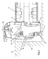
- Figure 2 is a section of the underground walkway with access to the support of the walkway.
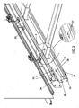
- Figure 3 is an isometric view of the profile with the crossbeams and the glass assembled.
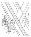
- Figure 4 is an isometric view of the discrete support part of the handrail.
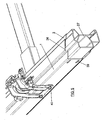
- Figure 5 depicts a continuous part which, tongued and grooved with the guide profile, performs the connection between profiles.
- Figure 6 depicts a type of anchor of the parts adjacent to the longitudinal member by means of a T-shaped roller path.
- the longitudinal guide members have a forward movement track, or upper track and a return track, or lower track, on which the support rollers 4 of the pallets 5 transporting users roll.
- Each longitudinal guide member has a symmetrical longitudinal member, both being connected by a connecting crossbeam 6 ensuring the distance between the guiding noses 7 of both longitudinal members.
- each longitudinal member and on its outermost face discrete parts 8 acting as a support for the glass of the handrail and as a support for the outer cover 9, for the outer profile 10 and for the base 11.
- the longitudinal members are longitudinal members comprising a plurality of profiles arranged laterally one after another to define a closed longitudinal member cross section contour.
- the longitudinal members are manufactured by rolling and subsequent laser welding of the profiles forming them, providing the necessary tolerances and allowing the absence of regulation in the assembly.
- these profiles have in their two inner surfaces, a third inclined surface 12' and a second vertical surface 12", to fix the position of the crossbeam 6 in relation to the profile 1 both vertically and transversely to the movement of the walkway.
- the fact that the cover is separate from the guide profile allows adopting different configurations cutting the profile at different levels in the vertical direction 13 depending on the level at which the ground is located.
- the cover can be fixed to the handrail support part 8 by means of anchoring surfaces 15 coming out of said part or even to the outer surface 16 of the guide profile.
- the outer profile 10 is screwed in the same manner to the discrete support part 8.
- Figure 2 shows an underground walkway with the pallets 5 at ground level 14.
- the supports 17 of the walkway can be accessed through the space 18 between the side 16 of the profile and the pit 19
- Figure 3 also shows one of the elongated holes 20 located in the upper part of the profile to allow regulation of the supports from the upper area of the profile.
- other elongated holes are arranged in alignment with the former at the lower part on which the supports 17 of the walkway are screwed in the event that there is sufficient space, as in the case of Figure 1 .
- the profile 1 has a first internal bend 21 for housing the support of the walkway and reducing the effective height of the walkway as in Figure 2 .
- the support is regulated by the space 18.
- a second internal bend 22 is equally included in the profile such that the cables 23 which have to be distributed along the entire length of the walkway can be housed.
- the guide profiles can be connected to one another by means of connecting parts 24 carried out as shown in Figure 3 .
- connecting parts 24 carried out as shown in Figure 3 .
- the track is further provided with continuity by means of the miter cut 26.
- the profiles can also be connected to one another by means of external connections 25 which are screwed directly to the elongated holes through both the inner part and the outer part of the profile.
- a profile 27 the shape of which coincides with the inside of the guide profile 1 can be arranged, making the tongue and grooving between two contiguous profiles complete.
- Figure 4 shows an image of the discrete support part of the handrail which is screwed to the upper part 28 of the profile and to the outer part 29.
- Figure 3 shows an image of the rolled profile 1 in which a series of elongated holes are punched:
- All these holes are punched during rolling, preventing any type of machining on the manufactured profile and therefore preventing any unnecessary cost.
- the elongated holes can also be replaced with T-shaped roller paths 41 such that the connection can be carried out at any point of the profile.
- One embodiment of the invention thus relates to a self-supporting guiding system for a conveyor system by means of pallets 5 provided with rollers 4 for guiding movement of the pallets 5.
- the generic term pallet comprises both plates of walkways and steps of stairs.
- the guiding system or frame comprises:
- At least,one of the two longitudinal members comprises at least one surface 7 forming an angle ⁇ 90° with at least one of the two tracks 2, 3 on each side of the roller 4 to prevent a transverse movement of the pallets 5.
- At least one of the two longitudinal members comprises at least one surface 7 forming an angle ⁇ 90° with at least one of the two tracks 2, 3, on one side of the roller 4 to prevent a transverse movement of the pallets 5.
- the means for fixing the longitudinal members additionally comprise a plurality of first elongated holes 37.
- the longitudinal members likewise comprise a plurality of profiles arranged laterally one after another to define a closed longitudinal member cross section contour.
- the longitudinal members have a constant cross section.
- the inner surface of the longitudinal members has a first vertical surface 12" and a third surface selected from inclined and horizontal 12' configured to form a transverse and vertical reference for positioning of the connecting crossbeam 6.
- the enclosure of the system is screwed to an element selected from the discrete part 8, the side of the longitudinal members, and combinations thereof to allow different configurations depending on the position of the system in relation to the ground or the product finishing needs.
- a large enough space is left between the enclosure 9 and the outside of the longitudinal members so as to access the support of the system when the system has an underground configuration.
- the discrete part 8 is manufactured by means of a process selected from casting, forging, press forming and combinations thereof.
- the system of the invention additionally comprises:
- the longitudinal members comprise a first internal bend 21 to provide a space in which there is arranged the support 17 of the system to reduce an effective height of the system.
- the longitudinal members comprise a second internal bend 22 to provide a space through which the cables circulate for the operation of the system.
- the longitudinal members are connected to one another by means of parts 27 copying an internal geometry of the longitudinal members, said parts 27 overlapping between two contiguous longitudinal members, each of the parts 27 being screwed to at least one fifth elongated hole 39 of each contiguous longitudinal member.
- the longitudinal members are connected by connecting parts 25 which externally connect two contiguous longitudinal members being screwed to sixth elongated holes 35 in the running direction of the system.
- At least one of the connecting crossbeams 6 is manufactured by means of a process selected from machining, extrusion, rolling, casting and combinations thereof.
- the longitudinal members are manufactured by rolling.
- the elongated holes 20, 39 and the anchors in the areas of the elongated holes 37, 36, 17', 35 are obtained by punching during the rolling process.
- the elongated holes 20, 39 are obtained by punching and the anchors in the areas of the elongated holes 37, 36, 17', 35 are carried out by means of a T-shaped roller path 41 during the rolling process.
- the discrete support part 8 comprises in an upper part at least three flanges 33 arranged on alternating sides of the handrail configured to press the handrail by means of at least one clamp screwed to the flanges of one side of the handrail 101 against the flanges of the other side of the handrail 101 to fix the handrail 101 to the frame.
Landscapes
- Escalators And Moving Walkways (AREA)
Claims (16)
- Fahrsteig-System über Paletten (5), ausgestattet mit Rollen (4), bestehend aus selbsttragenden Führungsmitteln zur Führung der Bewegung der Paletten (5), umfassend:einen ersten Längsträger und einen symmetrisch zum ersten Längsträger in Bezug auf eine longitudinale Mittelebene des Fördersystems angeordneten zweiten Längsträger, um eine Vorwärtsbewegungsschiene und eine Rücklaufschiene der Rollen (4) zu definieren;zumindest eine Verbindungstraverse (6) zur Verbindung der Längsträger; wobei die Längsträger umfassen:eine obere Oberfläche, die die Vorwärtsbewegungsschiene (2), auf der die Rollen (4) laufen, umfasst;eine untere Oberfläche, die die Rücklaufschiene (3), auf der die Rollen (4) laufen, umfasst;eine innere Oberfläche, die Mittel zur Befestigung der Längsträger umfasst;eine äußere Oberfläche;der erste Längsträger wird mit Hilfe von zumindest einer Verbindungstraverse (6) mit dem zweiten Längsträger verbunden, um eine notwendige Toleranz zwischen den Längsträgern zu gewährleisten;dadurch gekennzeichnet, dass:ein Gehäuse (9) des Fahrsteigs nicht direkt vom Führungsprofil gebildet wird, sondern separat angeordnet wird;die Längsträger eine Mehrzahl von seitlich nacheinander angeordneten Profilen umfassen, um eine geschlossene Längsträgerquerschnittskontur zu definieren.
- System nach Anspruch 1, dadurch gekennzeichnet, dass zumindest einer der beiden Längsträger zumindest eine Oberfläche (7), die einen Winkel von ≥90° mit zumindest einer der beiden Schienen (2, 3) auf beiden Seiten der Rolle (4) bildet, um eine Querbewegung der Paletten (5) zu verhindern, umfasst.
- System nach Anspruch 1, dadurch gekennzeichnet, dass zumindest einer der beiden Längsträger zumindest eine Oberfläche (7), die einen Winkel von ≥90° mit zumindest einer der beiden Schienen (2, 3) auf einer Seite der Rolle (4) bildet, um eine Querbewegung der Paletten (5) zu verhindern, umfasst.
- System nach einem der Ansprüche 1-3, dadurch gekennzeichnet, dass die Mittel zur Befestigung der Längsträger eine Mehrzahl von ersten Langlöchern (37) umfassen.
- System nach einem der Ansprüche 1-4, dadurch gekennzeichnet, dass die Mehrzahl von Profilen rollende Profile sind.
- System nach einem der Ansprüche 1-5, dadurch gekennzeichnet, dass die Längsträger einen konstanten Querschnitt aufweisen.
- System nach einem der Ansprüche 1-6, dadurch gekennzeichnet, dass die innere Oberfläche der Längsträger eine erste vertikale Oberfläche (12") und eine dritte Oberfläche, ausgewählt aus geneigter und horizontaler (12') aufweist, konfiguriert, um eine Quer- und Vertikalreferenz zur Positionierung der Verbindungstraverse (6) zu bilden.
- System nach einem der Ansprüche 1-7, dadurch gekennzeichnet, dass auf einer Oberfläche, ausgewählt aus der oberen Oberfläche (28), der äußeren Oberfläche (29) und Kombinationen davon, ein mit einer Mehrzahl von zweiten Langlöchern (36) verschraubtes diskretes Teil (8) aufliegt, konfiguriert zur:Sicherung eines Gehäuses des Systems;Unterstützung eines Glases, den Handlauf (101) des Systems bildend;Unterstützung eines äußeren Profils (10);Unterstützung einer Basis des Systems (11).
- System nach Anspruch 8, dadurch gekennzeichnet, dass das Gehäuse des Systems mit einem Element, ausgewählt aus dem diskreten Teil (8), der Seite der Längsträger und Kombinationen davon, verschraubt ist.
- System nach einem der Ansprüche 8-9, dadurch gekennzeichnet, dass ein ausreichend großer Raum zwischen dem Gehäuse (9) und der Außenseite der Längsträger vorhanden ist, um Zugriff zur Stütze des Systems zu haben, wenn das System eine unterirdische Konfiguration hat.
- System nach einem der Ansprüche 1-10, dadurch gekennzeichnet, dass es
eine Mehrzahl dritter Langlöcher (17') in der unteren Oberfläche, auf der die Stützen (17) des Systems an einer Stelle, ausgewählt aus dem Boden, einem Verstärkungsrahmen und Kombinationen davon, montiert sind,
eine Mehrzahl vierter Langlöcher (20) in der oberen Oberfläche (28), um einen Zugriff zur Regulierung der Stütze (17) zu ermöglichen, umfasst. - System nach Anspruch 11, dadurch gekennzeichnet, dass die Längsträger eine erste interne Biegung (21) umfassen, zur Bereitstellung eines Raumes, in dem die Stütze (17) des Systems angebracht ist, um eine effektive Höhe des Systems zu reduzieren.
- System nach einem der Ansprüche 1-12, dadurch gekennzeichnet, dass die Längsträger eine zweite interne Biegung (22) umfassen, zur Bereitstellung eines Raumes, durch den die Kabel für den Betrieb des Systems zirkulieren.
- System nach einem der Ansprüche 1-13, dadurch gekennzeichnet, dass die Längsträger mit Hilfe von Teilen (27), die eine interne Geometrie der Längsträger nachbilden, miteinander verbunden sind, wobei sich die Teile (27) zwischen zwei benachbarten Längsträgern überlappen, wobei jedes der Teile (27) mit zumindest einem fünften Langloch (39) des jeweiligen benachbarten Längsträgers verschraubt wird.
- System nach einem der Ansprüche 1-14, dadurch gekennzeichnet, dass die Längsträger mit Hilfe von Verbindungsteilen (25), die extern zwei benachbarte Längsträger verbinden, verbunden sind, wobei sie mit sechsten Langlöchern (35) in Laufrichtung des Systems verschraubt werden.
- System nach einem der Ansprüche 8-15, dadurch gekennzeichnet, dass das diskrete Stützteil (8) in einem oberen Teil zumindest drei, an beiden Seiten des Handlaufes wechselweise angebrachte Flansche (33) umfasst, konfiguriert, um den Handlauf mittels zumindest einer mit den Flanschen einer Seite des Handlaufes (101) verschraubten Klemme gegen die Flansche der anderen Seite des Handlaufes (101) zu drücken, um den Handlauf (101) an dem Rahmen festzumachen.
Applications Claiming Priority (1)
| Application Number | Priority Date | Filing Date | Title |
|---|---|---|---|
| ES200702739A ES2299408B1 (es) | 2007-10-18 | 2007-10-18 | Sistema de guiado autoportante para pasillos rodantes. |
Publications (3)
| Publication Number | Publication Date |
|---|---|
| EP2050708A2 EP2050708A2 (de) | 2009-04-22 |
| EP2050708A3 EP2050708A3 (de) | 2009-07-22 |
| EP2050708B1 true EP2050708B1 (de) | 2015-08-12 |
Family
ID=39357410
Family Applications (1)
| Application Number | Title | Priority Date | Filing Date |
|---|---|---|---|
| EP08380203.3A Active EP2050708B1 (de) | 2007-10-18 | 2008-07-07 | Beweglicher Fahrsteig bestehend aus Selbststützendes Führungssystem |
Country Status (4)
| Country | Link |
|---|---|
| US (1) | US8042675B2 (de) |
| EP (1) | EP2050708B1 (de) |
| CN (1) | CN101412484B (de) |
| ES (2) | ES2299408B1 (de) |
Families Citing this family (8)
| Publication number | Priority date | Publication date | Assignee | Title |
|---|---|---|---|---|
| ES2322536B1 (es) * | 2008-12-12 | 2010-07-07 | Tyhyssenkrupp Elevator Innovation Center, S.A. | Estructura portante para sistemas de transporte de personas y/o mercancias. |
| TWI597230B (zh) * | 2012-09-27 | 2017-09-01 | 伊文修股份有限公司 | 具有階梯輸送帶的手扶梯、具有板狀輸送帶的自動走道及導引片 |
| TWI593618B (zh) | 2012-09-27 | 2017-08-01 | 伊文修股份有限公司 | 手扶梯或自動走道的軌道模組、手扶梯、自動走道、組裝手扶梯或自動走道的方法以及將手扶梯或自動走道現代化的方法 |
| US9239105B2 (en) * | 2013-10-11 | 2016-01-19 | Kone Corporation | Power transmission system for people mover |
| WO2015100749A1 (en) * | 2014-01-06 | 2015-07-09 | Kone Corporation | Moving walk |
| BR112016025014A2 (pt) * | 2014-04-30 | 2017-10-24 | Inventio Ag | sistema de trilho para uma escada rolante ou uma esteira rolante |
| ES2900448T3 (es) * | 2015-06-25 | 2022-03-17 | Tk Elevator Innovation Center S A | Cercha modular para escaleras mecánicas/pasillos rodantes y procedimiento de ensamblaje de una cercha modular para escaleras mecánicas/pasillos rodantes |
| EP3447021B1 (de) | 2017-08-21 | 2023-05-24 | TK Escalator Norte, S.A. | Transportvorrichtung |
Family Cites Families (25)
| Publication number | Priority date | Publication date | Assignee | Title |
|---|---|---|---|---|
| US2656031A (en) * | 1950-07-07 | 1953-10-20 | Multiscope Inc | Moving stairway |
| US4064986A (en) * | 1976-04-30 | 1977-12-27 | Westinghouse Electric Corporation | Escalator having guide wheels and guide track with cooperative non-flat surfaces |
| US4159758A (en) * | 1977-09-19 | 1979-07-03 | Westinghouse Electric Corp. | Transportation apparatus |
| CH648811A5 (de) * | 1980-12-23 | 1985-04-15 | Inventio Ag | Fuehrungseinrichtung fuer die laufelemente von endlosfoerderern, insbesondere fahrtreppen. |
| US4381851A (en) * | 1981-03-11 | 1983-05-03 | Westinghouse Electric Corp. | Track splice |
| KR890004008Y1 (ko) * | 1983-09-19 | 1989-06-15 | 미쓰비시전기 주식회사 | 곡선 에스컬레이터 |
| KR890003872Y1 (ko) * | 1983-11-11 | 1989-06-08 | 미쓰비시전기 주식회사 | 곡선 에스컬레이터의 메인프레임(main frame) |
| US4690264A (en) * | 1986-03-31 | 1987-09-01 | Otis Elevator Company | Multifunction glassholder for escalator balustrade |
| GB2215122A (en) * | 1988-02-12 | 1989-09-13 | Philips Electronic Associated | A method of forming a quantum dot structure |
| JPH0735236B2 (ja) * | 1988-06-06 | 1995-04-19 | 株式会社日立製作所 | 乗客コンベア用枠体 |
| JPH04145919A (ja) * | 1990-10-04 | 1992-05-19 | Kotaro Matsui | 巻線多重回転機 |
| US5601179A (en) * | 1993-01-22 | 1997-02-11 | Otis Elevator Company | Balustrade skirt panel |
| WO1998057880A1 (fr) * | 1997-06-17 | 1998-12-23 | Nippon Fillestar Co., Ltd. | Systeme de transport de pietons |
| ZA996982B (en) * | 1998-11-25 | 2000-05-18 | Inventio Ag | Equipment for the fastening of guide rollers of an escalator step of a moving walkway plate. |
| JP4824157B2 (ja) * | 1999-08-06 | 2011-11-30 | インベンテイオ・アクテイエンゲゼルシヤフト | 長いエスカレータと動く歩道の支持構造体 |
| EP1074507B1 (de) | 1999-08-06 | 2004-12-15 | Inventio Ag | Tragkonstruktion für lange Fahrtreppen und Fahrsteige |
| JP4688276B2 (ja) * | 2000-11-09 | 2011-05-25 | 東芝エレベータ株式会社 | 乗客コンベア装置 |
| US20020175039A1 (en) * | 2001-05-11 | 2002-11-28 | Fargo Richard N. | Escalator support structure |
| MY129702A (en) * | 2001-12-19 | 2007-04-30 | Inventio Ag | Support construction |
| US6860383B2 (en) * | 2002-03-07 | 2005-03-01 | Rapistan Systems Advertising Corp. | Positive displacement sorter |
| DE10300587A1 (de) * | 2003-01-10 | 2004-07-22 | Kone Corp. | Führungssystem für Rollen von Stufen und Paletten einer Personenförderanlage |
| JP4368178B2 (ja) * | 2003-10-10 | 2009-11-18 | 東芝エレベータ株式会社 | 乗客コンベア |
| FI20040090L (fi) * | 2004-01-22 | 2005-07-23 | Kone Corp | Liukukäytävä, -ramppi tai -porras |
| FI20040091L (fi) * | 2004-01-22 | 2005-07-23 | Kone Corp | Liukukäytävä, -ramppi tai -porras |
| DE202004004178U1 (de) * | 2004-03-17 | 2004-09-23 | Thyssenkrupp Fahrtreppen Gmbh | Fahrtreppe oder Fahrsteig |
-
2007
- 2007-10-18 ES ES200702739A patent/ES2299408B1/es active Active
-
2008
- 2008-07-07 ES ES08380203.3T patent/ES2552755T3/es active Active
- 2008-07-07 EP EP08380203.3A patent/EP2050708B1/de active Active
- 2008-09-01 CN CN200810211174.7A patent/CN101412484B/zh active Active
- 2008-10-08 US US12/247,762 patent/US8042675B2/en active Active
Also Published As
| Publication number | Publication date |
|---|---|
| ES2552755T3 (es) | 2015-12-02 |
| EP2050708A3 (de) | 2009-07-22 |
| ES2299408A1 (es) | 2008-05-16 |
| CN101412484A (zh) | 2009-04-22 |
| ES2299408B1 (es) | 2009-06-12 |
| EP2050708A2 (de) | 2009-04-22 |
| CN101412484B (zh) | 2014-03-12 |
| US20090101470A1 (en) | 2009-04-23 |
| US8042675B2 (en) | 2011-10-25 |
Similar Documents
| Publication | Publication Date | Title |
|---|---|---|
| US8042675B2 (en) | Self-supporting guiding system for moving walkways | |
| EP3109195B1 (de) | Modularer fahrtreppen-/fahrsteigträger und verfahren zur montage eines modularen fahrtreppen-/fahrsteigträgers | |
| US9718648B2 (en) | Moving walk | |
| EP3177788A1 (de) | Tragende elemente einer tragenden struktur, dazugehörige verbindungselemente, sowie vorrichtungen und verfahren zur herstellung derselben | |
| US8919527B2 (en) | Conveying equipment for persons | |
| US9944496B2 (en) | Track system for an escalator or a moving walkway | |
| FI91181C (fi) | Teräsbetoninen liittorakenne | |
| US9145284B2 (en) | Method for producing a track and track for a track lifting device | |
| CA2579307C (en) | Lift cage and method for the installation of a lift | |
| EP2944599B1 (de) | Hub- und handhabungsvorrichtung | |
| EP3081520A1 (de) | Verfahren zur installation einer führungsschiene und eine führungsschiene | |
| WO2014121972A1 (en) | Method of manufacturing a beam | |
| EP3231760A1 (de) | Befestigungsmodule und paletten für eine palettentransportvorrichtung | |
| Groche et al. | Bending–rolling combinations for strips with optimized cross-section geometries | |
| CA2578578A1 (en) | Elevator cage and method for the installation an elevator cage | |
| GB2581240A (en) | A structural member | |
| JP5454679B2 (ja) | 乗客コンベア | |
| KR200209562Y1 (ko) | 넓이 조절이 가능한 거푸집 | |
| EP1328460B1 (de) | Stützstruktur für aufzugsführungsschienen | |
| US12240734B2 (en) | Elevator guide rail | |
| DK2199496T3 (en) | STORAGE UNIT FOR COVERING AN INSTALLATION EXCAVATION | |
| CN120457085A (zh) | 电梯设备的导轨元件和导轨结构以及相应的装配方法 | |
| KR20260061618A (ko) | 조립식 랙 구조물 및 그 조립 방법 | |
| HK1234023A1 (en) | Guide rail arrangement and method for installing guide rails | |
| HK1143793B (en) | Passenger conveyor |
Legal Events
| Date | Code | Title | Description |
|---|---|---|---|
| PUAI | Public reference made under article 153(3) epc to a published international application that has entered the european phase |
Free format text: ORIGINAL CODE: 0009012 |
|
| AK | Designated contracting states |
Kind code of ref document: A2 Designated state(s): AT BE BG CH CY CZ DE DK EE ES FI FR GB GR HR HU IE IS IT LI LT LU LV MC MT NL NO PL PT RO SE SI SK TR |
|
| AX | Request for extension of the european patent |
Extension state: AL BA MK RS |
|
| PUAL | Search report despatched |
Free format text: ORIGINAL CODE: 0009013 |
|
| AK | Designated contracting states |
Kind code of ref document: A3 Designated state(s): AT BE BG CH CY CZ DE DK EE ES FI FR GB GR HR HU IE IS IT LI LT LU LV MC MT NL NO PL PT RO SE SI SK TR |
|
| AX | Request for extension of the european patent |
Extension state: AL BA MK RS |
|
| 17P | Request for examination filed |
Effective date: 20091020 |
|
| 17Q | First examination report despatched |
Effective date: 20091204 |
|
| AKX | Designation fees paid |
Designated state(s): AT BE BG CH CY CZ DE DK EE ES FI FR GB GR HR HU IE IS IT LI LT LU LV MC MT NL NO PL PT RO SE SI SK TR |
|
| GRAP | Despatch of communication of intention to grant a patent |
Free format text: ORIGINAL CODE: EPIDOSNIGR1 |
|
| INTG | Intention to grant announced |
Effective date: 20150413 |
|
| GRAS | Grant fee paid |
Free format text: ORIGINAL CODE: EPIDOSNIGR3 |
|
| GRAA | (expected) grant |
Free format text: ORIGINAL CODE: 0009210 |
|
| AK | Designated contracting states |
Kind code of ref document: B1 Designated state(s): AT BE BG CH CY CZ DE DK EE ES FI FR GB GR HR HU IE IS IT LI LT LU LV MC MT NL NO PL PT RO SE SI SK TR |
|
| REG | Reference to a national code |
Ref country code: GB Ref legal event code: FG4D |
|
| REG | Reference to a national code |
Ref country code: CH Ref legal event code: EP |
|
| REG | Reference to a national code |
Ref country code: AT Ref legal event code: REF Ref document number: 741956 Country of ref document: AT Kind code of ref document: T Effective date: 20150815 |
|
| REG | Reference to a national code |
Ref country code: IE Ref legal event code: FG4D |
|
| REG | Reference to a national code |
Ref country code: DE Ref legal event code: R096 Ref document number: 602008039484 Country of ref document: DE |
|
| REG | Reference to a national code |
Ref country code: DE Ref legal event code: R081 Ref document number: 602008039484 Country of ref document: DE Owner name: THYSSENKRUPP ELEVATOR INNOVATION CENTER S.A., , ES Free format text: FORMER OWNERS: THYSSENKRUPP ELEVATOR (ES/PBB) LTD., STAINES, LONDON, GB; THYSSENKRUPP ELEVATOR INNOVATION CENTER S.A., GIJON ASTURIAS, ES |
|
| REG | Reference to a national code |
Ref country code: ES Ref legal event code: FG2A Ref document number: 2552755 Country of ref document: ES Kind code of ref document: T3 Effective date: 20151202 |
|
| RAP2 | Party data changed (patent owner data changed or rights of a patent transferred) |
Owner name: THYSSENKRUPP ELEVATOR INNOVATION CENTER S.A. |
|
| REG | Reference to a national code |
Ref country code: LT Ref legal event code: MG4D |
|
| REG | Reference to a national code |
Ref country code: NL Ref legal event code: MP Effective date: 20150812 |
|
| PG25 | Lapsed in a contracting state [announced via postgrant information from national office to epo] |
Ref country code: NO Free format text: LAPSE BECAUSE OF FAILURE TO SUBMIT A TRANSLATION OF THE DESCRIPTION OR TO PAY THE FEE WITHIN THE PRESCRIBED TIME-LIMIT Effective date: 20151112 Ref country code: LT Free format text: LAPSE BECAUSE OF FAILURE TO SUBMIT A TRANSLATION OF THE DESCRIPTION OR TO PAY THE FEE WITHIN THE PRESCRIBED TIME-LIMIT Effective date: 20150812 Ref country code: LV Free format text: LAPSE BECAUSE OF FAILURE TO SUBMIT A TRANSLATION OF THE DESCRIPTION OR TO PAY THE FEE WITHIN THE PRESCRIBED TIME-LIMIT Effective date: 20150812 |
|
| PG25 | Lapsed in a contracting state [announced via postgrant information from national office to epo] |
Ref country code: PL Free format text: LAPSE BECAUSE OF FAILURE TO SUBMIT A TRANSLATION OF THE DESCRIPTION OR TO PAY THE FEE WITHIN THE PRESCRIBED TIME-LIMIT Effective date: 20150812 Ref country code: IS Free format text: LAPSE BECAUSE OF FAILURE TO SUBMIT A TRANSLATION OF THE DESCRIPTION OR TO PAY THE FEE WITHIN THE PRESCRIBED TIME-LIMIT Effective date: 20151212 Ref country code: PT Free format text: LAPSE BECAUSE OF FAILURE TO SUBMIT A TRANSLATION OF THE DESCRIPTION OR TO PAY THE FEE WITHIN THE PRESCRIBED TIME-LIMIT Effective date: 20151214 Ref country code: HR Free format text: LAPSE BECAUSE OF FAILURE TO SUBMIT A TRANSLATION OF THE DESCRIPTION OR TO PAY THE FEE WITHIN THE PRESCRIBED TIME-LIMIT Effective date: 20150812 Ref country code: SE Free format text: LAPSE BECAUSE OF FAILURE TO SUBMIT A TRANSLATION OF THE DESCRIPTION OR TO PAY THE FEE WITHIN THE PRESCRIBED TIME-LIMIT Effective date: 20150812 |
|
| PG25 | Lapsed in a contracting state [announced via postgrant information from national office to epo] |
Ref country code: NL Free format text: LAPSE BECAUSE OF FAILURE TO SUBMIT A TRANSLATION OF THE DESCRIPTION OR TO PAY THE FEE WITHIN THE PRESCRIBED TIME-LIMIT Effective date: 20150812 |
|
| PG25 | Lapsed in a contracting state [announced via postgrant information from national office to epo] |
Ref country code: EE Free format text: LAPSE BECAUSE OF FAILURE TO SUBMIT A TRANSLATION OF THE DESCRIPTION OR TO PAY THE FEE WITHIN THE PRESCRIBED TIME-LIMIT Effective date: 20150812 Ref country code: DK Free format text: LAPSE BECAUSE OF FAILURE TO SUBMIT A TRANSLATION OF THE DESCRIPTION OR TO PAY THE FEE WITHIN THE PRESCRIBED TIME-LIMIT Effective date: 20150812 |
|
| REG | Reference to a national code |
Ref country code: DE Ref legal event code: R097 Ref document number: 602008039484 Country of ref document: DE |
|
| PG25 | Lapsed in a contracting state [announced via postgrant information from national office to epo] |
Ref country code: RO Free format text: LAPSE BECAUSE OF FAILURE TO SUBMIT A TRANSLATION OF THE DESCRIPTION OR TO PAY THE FEE WITHIN THE PRESCRIBED TIME-LIMIT Effective date: 20150812 |
|
| REG | Reference to a national code |
Ref country code: SK Ref legal event code: T3 Ref document number: E 20163 Country of ref document: SK |
|
| PLBE | No opposition filed within time limit |
Free format text: ORIGINAL CODE: 0009261 |
|
| STAA | Information on the status of an ep patent application or granted ep patent |
Free format text: STATUS: NO OPPOSITION FILED WITHIN TIME LIMIT |
|
| 26N | No opposition filed |
Effective date: 20160513 |
|
| REG | Reference to a national code |
Ref country code: FR Ref legal event code: PLFP Year of fee payment: 9 |
|
| PG25 | Lapsed in a contracting state [announced via postgrant information from national office to epo] |
Ref country code: SI Free format text: LAPSE BECAUSE OF FAILURE TO SUBMIT A TRANSLATION OF THE DESCRIPTION OR TO PAY THE FEE WITHIN THE PRESCRIBED TIME-LIMIT Effective date: 20150812 |
|
| PG25 | Lapsed in a contracting state [announced via postgrant information from national office to epo] |
Ref country code: BE Free format text: LAPSE BECAUSE OF FAILURE TO SUBMIT A TRANSLATION OF THE DESCRIPTION OR TO PAY THE FEE WITHIN THE PRESCRIBED TIME-LIMIT Effective date: 20150812 |
|
| REG | Reference to a national code |
Ref country code: CH Ref legal event code: PL |
|
| GBPC | Gb: european patent ceased through non-payment of renewal fee |
Effective date: 20160707 |
|
| PG25 | Lapsed in a contracting state [announced via postgrant information from national office to epo] |
Ref country code: MC Free format text: LAPSE BECAUSE OF FAILURE TO SUBMIT A TRANSLATION OF THE DESCRIPTION OR TO PAY THE FEE WITHIN THE PRESCRIBED TIME-LIMIT Effective date: 20150812 |
|
| PG25 | Lapsed in a contracting state [announced via postgrant information from national office to epo] |
Ref country code: LI Free format text: LAPSE BECAUSE OF NON-PAYMENT OF DUE FEES Effective date: 20160731 Ref country code: CH Free format text: LAPSE BECAUSE OF NON-PAYMENT OF DUE FEES Effective date: 20160731 |
|
| REG | Reference to a national code |
Ref country code: IE Ref legal event code: MM4A |
|
| PG25 | Lapsed in a contracting state [announced via postgrant information from national office to epo] |
Ref country code: GB Free format text: LAPSE BECAUSE OF NON-PAYMENT OF DUE FEES Effective date: 20160707 |
|
| REG | Reference to a national code |
Ref country code: FR Ref legal event code: PLFP Year of fee payment: 10 |
|
| PG25 | Lapsed in a contracting state [announced via postgrant information from national office to epo] |
Ref country code: IE Free format text: LAPSE BECAUSE OF NON-PAYMENT OF DUE FEES Effective date: 20160707 |
|
| PG25 | Lapsed in a contracting state [announced via postgrant information from national office to epo] |
Ref country code: LU Free format text: LAPSE BECAUSE OF NON-PAYMENT OF DUE FEES Effective date: 20160707 |
|
| PGFP | Annual fee paid to national office [announced via postgrant information from national office to epo] |
Ref country code: CH Payment date: 20170724 Year of fee payment: 10 |
|
| REG | Reference to a national code |
Ref country code: AT Ref legal event code: UEP Ref document number: 741956 Country of ref document: AT Kind code of ref document: T Effective date: 20150812 |
|
| PG25 | Lapsed in a contracting state [announced via postgrant information from national office to epo] |
Ref country code: HU Free format text: LAPSE BECAUSE OF FAILURE TO SUBMIT A TRANSLATION OF THE DESCRIPTION OR TO PAY THE FEE WITHIN THE PRESCRIBED TIME-LIMIT; INVALID AB INITIO Effective date: 20080707 Ref country code: CY Free format text: LAPSE BECAUSE OF FAILURE TO SUBMIT A TRANSLATION OF THE DESCRIPTION OR TO PAY THE FEE WITHIN THE PRESCRIBED TIME-LIMIT Effective date: 20150812 |
|
| PG25 | Lapsed in a contracting state [announced via postgrant information from national office to epo] |
Ref country code: MT Free format text: LAPSE BECAUSE OF NON-PAYMENT OF DUE FEES Effective date: 20160731 Ref country code: GR Free format text: LAPSE BECAUSE OF FAILURE TO SUBMIT A TRANSLATION OF THE DESCRIPTION OR TO PAY THE FEE WITHIN THE PRESCRIBED TIME-LIMIT Effective date: 20150812 |
|
| PG25 | Lapsed in a contracting state [announced via postgrant information from national office to epo] |
Ref country code: BG Free format text: LAPSE BECAUSE OF FAILURE TO SUBMIT A TRANSLATION OF THE DESCRIPTION OR TO PAY THE FEE WITHIN THE PRESCRIBED TIME-LIMIT Effective date: 20150812 |
|
| PG25 | Lapsed in a contracting state [announced via postgrant information from national office to epo] |
Ref country code: FR Free format text: LAPSE BECAUSE OF NON-PAYMENT OF DUE FEES Effective date: 20180731 |
|
| PG25 | Lapsed in a contracting state [announced via postgrant information from national office to epo] |
Ref country code: IT Free format text: LAPSE BECAUSE OF NON-PAYMENT OF DUE FEES Effective date: 20180707 |
|
| P01 | Opt-out of the competence of the unified patent court (upc) registered |
Effective date: 20230526 |
|
| PGFP | Annual fee paid to national office [announced via postgrant information from national office to epo] |
Ref country code: TR Payment date: 20240628 Year of fee payment: 17 |
|
| PGFP | Annual fee paid to national office [announced via postgrant information from national office to epo] |
Ref country code: FI Payment date: 20240722 Year of fee payment: 17 |
|
| PGFP | Annual fee paid to national office [announced via postgrant information from national office to epo] |
Ref country code: CZ Payment date: 20240628 Year of fee payment: 17 |
|
| PGFP | Annual fee paid to national office [announced via postgrant information from national office to epo] |
Ref country code: AT Payment date: 20240722 Year of fee payment: 17 |
|
| PGFP | Annual fee paid to national office [announced via postgrant information from national office to epo] |
Ref country code: SK Payment date: 20250630 Year of fee payment: 18 |
|
| PGFP | Annual fee paid to national office [announced via postgrant information from national office to epo] |
Ref country code: ES Payment date: 20250826 Year of fee payment: 18 |
|
| PGFP | Annual fee paid to national office [announced via postgrant information from national office to epo] |
Ref country code: DE Payment date: 20250722 Year of fee payment: 18 |
|
| PG25 | Lapsed in a contracting state [announced via postgrant information from national office to epo] |
Ref country code: CZ Free format text: LAPSE BECAUSE OF NON-PAYMENT OF DUE FEES Effective date: 20250707 |
|
| REG | Reference to a national code |
Ref country code: AT Ref legal event code: MM01 Ref document number: 741956 Country of ref document: AT Kind code of ref document: T Effective date: 20250707 |
|
| PG25 | Lapsed in a contracting state [announced via postgrant information from national office to epo] |
Ref country code: AT Free format text: LAPSE BECAUSE OF NON-PAYMENT OF DUE FEES Effective date: 20250707 Ref country code: FI Free format text: LAPSE BECAUSE OF NON-PAYMENT OF DUE FEES Effective date: 20250707 |