EP2050552B1 - Dispositif de sortie de produits en vrac - Google Patents
Dispositif de sortie de produits en vrac Download PDFInfo
- Publication number
- EP2050552B1 EP2050552B1 EP20080166994 EP08166994A EP2050552B1 EP 2050552 B1 EP2050552 B1 EP 2050552B1 EP 20080166994 EP20080166994 EP 20080166994 EP 08166994 A EP08166994 A EP 08166994A EP 2050552 B1 EP2050552 B1 EP 2050552B1
- Authority
- EP
- European Patent Office
- Prior art keywords
- intermediate plate
- receptacle
- granular material
- bulk material
- opening
- Prior art date
- Legal status (The legal status is an assumption and is not a legal conclusion. Google has not performed a legal analysis and makes no representation as to the accuracy of the status listed.)
- Active
Links
Images

Classifications
-
- B—PERFORMING OPERATIONS; TRANSPORTING
- B65—CONVEYING; PACKING; STORING; HANDLING THIN OR FILAMENTARY MATERIAL
- B65G—TRANSPORT OR STORAGE DEVICES, e.g. CONVEYORS FOR LOADING OR TIPPING, SHOP CONVEYOR SYSTEMS OR PNEUMATIC TUBE CONVEYORS
- B65G65/00—Loading or unloading
- B65G65/30—Methods or devices for filling or emptying bunkers, hoppers, tanks, or like containers, of interest apart from their use in particular chemical or physical processes or their application in particular machines, e.g. not covered by a single other subclass
- B65G65/34—Emptying devices
- B65G65/40—Devices for emptying otherwise than from the top
- B65G65/48—Devices for emptying otherwise than from the top using other rotating means, e.g. rotating pressure sluices in pneumatic systems
- B65G65/4809—Devices for emptying otherwise than from the top using other rotating means, e.g. rotating pressure sluices in pneumatic systems rotating about a substantially vertical axis
- B65G65/4836—Devices for emptying otherwise than from the top using other rotating means, e.g. rotating pressure sluices in pneumatic systems rotating about a substantially vertical axis and moving material over a stationary surface, e.g. sweep arms or wheels
-
- B—PERFORMING OPERATIONS; TRANSPORTING
- B01—PHYSICAL OR CHEMICAL PROCESSES OR APPARATUS IN GENERAL
- B01J—CHEMICAL OR PHYSICAL PROCESSES, e.g. CATALYSIS OR COLLOID CHEMISTRY; THEIR RELEVANT APPARATUS
- B01J2/00—Processes or devices for granulating materials, e.g. fertilisers in general; Rendering particulate materials free flowing in general, e.g. making them hydrophobic
- B01J2/10—Processes or devices for granulating materials, e.g. fertilisers in general; Rendering particulate materials free flowing in general, e.g. making them hydrophobic in stationary drums or troughs, provided with kneading or mixing appliances
-
- B—PERFORMING OPERATIONS; TRANSPORTING
- B29—WORKING OF PLASTICS; WORKING OF SUBSTANCES IN A PLASTIC STATE IN GENERAL
- B29B—PREPARATION OR PRETREATMENT OF THE MATERIAL TO BE SHAPED; MAKING GRANULES OR PREFORMS; RECOVERY OF PLASTICS OR OTHER CONSTITUENTS OF WASTE MATERIAL CONTAINING PLASTICS
- B29B17/00—Recovery of plastics or other constituents of waste material containing plastics
- B29B17/04—Disintegrating plastics, e.g. by milling
- B29B17/0412—Disintegrating plastics, e.g. by milling to large particles, e.g. beads, granules, flakes, slices
-
- B—PERFORMING OPERATIONS; TRANSPORTING
- B29—WORKING OF PLASTICS; WORKING OF SUBSTANCES IN A PLASTIC STATE IN GENERAL
- B29K—INDEXING SCHEME ASSOCIATED WITH SUBCLASSES B29B, B29C OR B29D, RELATING TO MOULDING MATERIALS OR TO MATERIALS FOR MOULDS, REINFORCEMENTS, FILLERS OR PREFORMED PARTS, e.g. INSERTS
- B29K2067/00—Use of polyesters or derivatives thereof, as moulding material
-
- Y—GENERAL TAGGING OF NEW TECHNOLOGICAL DEVELOPMENTS; GENERAL TAGGING OF CROSS-SECTIONAL TECHNOLOGIES SPANNING OVER SEVERAL SECTIONS OF THE IPC; TECHNICAL SUBJECTS COVERED BY FORMER USPC CROSS-REFERENCE ART COLLECTIONS [XRACs] AND DIGESTS
- Y02—TECHNOLOGIES OR APPLICATIONS FOR MITIGATION OR ADAPTATION AGAINST CLIMATE CHANGE
- Y02W—CLIMATE CHANGE MITIGATION TECHNOLOGIES RELATED TO WASTEWATER TREATMENT OR WASTE MANAGEMENT
- Y02W30/00—Technologies for solid waste management
- Y02W30/50—Reuse, recycling or recovery technologies
- Y02W30/62—Plastics recycling; Rubber recycling
Definitions
- the present invention relates to a device for discharging bulk material.
- a device for discharging bulk material In the context of recycling processes for plastic bottles and in particular for PET bottles, it is customary to crush these bottles and then to clean the crushed items or flakes, for subsequent recycling. As part of this recycling process, it is necessary in some processes to remove the bulk material from a container. In this removal of the bulk material, there is often the problem that the bulk material bridges or wedge some particles of this bulk material together.
- a device for discharging bulk material is from the JP-A-61018642 known. The present invention is therefore based on the object to provide a discharge floor, which is also suitable for bridging bulk materials. The invention will be described with reference to PET flakes from a recycling process, but it will be understood that the invention is also suitable for other bulk materials.
- An inventive device for discharging bulk material has a container into which bulk material can be filled. Furthermore, a distribution grid arranged in the container and an intermediate plate arranged below this distribution grid are provided, wherein the intermediate plate has at least one passage opening for the bulk material. Furthermore, an opening is provided below the intermediate plate, through which the bulk material can be removed from the container. According to the invention Rotatable intermediate plate relative to the distribution grid and the distribution grid stationary relative to the container.
- the area above the intermediate plate is divided into several segments and anschmanend is effected by the rotation of the intermediate plate that the cargo can fall through the passage opening in the intermediate plate. By segmenting the surface above the intermediate plate bridging of the bulk material is prevented.
- the container has a flange device to be flanged to silos, storage, reaction container or the like. More specifically, preferably the entire device is flanged down to silos, storage, reaction vessels or the like, which silos may be cylindrical, conical-closing, conically opening or square.
- the device thus consists of a two-chamber system, wherein a chamber is arranged above the intermediate plate and the other chamber below the intermediate plate.
- the upper area that is, the area above the intermediate plate serves as a storage chamber and also contains the stationary distribution grate (also referred to as Austragsgitter).
- the discharge chamber Below the intermediate plate is the discharge chamber. From this area, the bulk material is discharged from the device and thus from the silo and preferably fed to another unit or other transport systems, such as conveyor belts or trucks. More specifically, for discharging the bulk material, the opening provided below the intermediate plate serves.
- a base plate opposite the container is provided below the intermediate plate and the opening is arranged in this base plate.
- the bulk material can fall through the passage opening of the intermediate plate on the bottom plate during operation.
- a relative to the container rotatable displacement device is provided for this purpose above the bottom plate, which shifts the bulk material relative to the bottom plate. More specifically, in this discharge chamber, that is, the area above the bottom plate, the bulk material is discharged through a rotating rake through the opening or pipe.
- the discharge tray according to the invention for bulk materials of any kind is suitable. Even problematic bulk goods with a tendency to bridge formation can be discharged more uniformly by this discharge.
- the displacement device has a curvature adapted to an opening cross section of the opening in the base plate.
- the displacement device or the rake is curved such that the bulk material is forced into those radial region of the bottom plate, in which the opening is located. More specifically, the bulk material is urged in the movement of the displacement device in a region of the displacement device, which forms a recess in the direction of rotation. In this area, the opening in the bottom plate is provided.
- the rake can also be curved straight or negative.
- the passage opening is a slot extending in a radial direction of the intermediate plate.
- a plurality of such slots may also be provided.
- the passage opening extends substantially along substantially the entire radial length of the intermediate plate, so that in the entire radial region, the bulk material can pass through the intermediate plate.
- passage openings are provided in the form of slots, these are particularly preferably substantially uniformly distributed in the circumferential direction.
- the intermediate plate in the direction of rotation in front of the passage opening on an inclined surface, which preferably covers the passage opening located below this inclined surface.
- this rotating intermediate plate may have one or more discharge slots.
- this inclined surface ensures during the rotation of the intermediate plate for a compression of the bulk material immediately before the inclined surface or ramp, so that compressed material is relieved behind the ramp and through the intermediate plate therethrough falls into the discharge chamber.
- the inclined surface or ramp between 20 ° and 30 ° relative to the plane of the intermediate plate is inclined.
- the number and shape of these discharge slots or passage openings is adapted to the bulk material and is closely related to the entire base area of the device.
- the distribution grille is thus preferably made of vertically installed surfaces, that is perpendicular to the intermediate plate standing sheets and arranged below the emptying floor.
- the device has a drive device which drives the intermediate plate and this drive device is provided below the container.
- this drive device is provided below the container.
- the intermediate plate rotates at a speed between 1 rpm and 10 rpm, preferably between 1 rpm and 7 rpm and, in particular in the case of industrial applications, between 1 rpm and 3 rpm.
- the drive motor is frequency-controlled.
- the distribution grid has between three and twelve, preferably between four and ten and more preferably between four and eight arms extending in the radial direction of the intermediate plate.
- these arms or these star-shaped arranged vertical plates are pointed upwards to avoid any bridging.
- the lower the number of these arms or plates the greater the tendency for rearward mixing of the bulk material.
- the greater the number of these arms or plates the higher the risk of bridging in the device.
- the distribution grid is spaced from the intermediate plate.
- the emptying of the intermediate plate schabend and in this way the core flow is minimized.
- the bulk material from the container according to the "first-in-first-out principle".
- the use is also conceivable for all types of time-controlled processes in reactors.
- the distance between the arms and the intermediate plate is between 10mm and 20mm.
- the device has a centrally arranged conical distributor body above the intermediate plate. It is particularly preferred that this conical body is arranged so that its axis of symmetry coincides with the axis of symmetry of the intermediate plate. This cone causes almost complete emptying of the silo, which is particularly advantageous for processes where product changes are required. Preferably, this conical body rotates together with the intermediate plate.
- the storage chamber which is formed above the intermediate plate, consists of a preferably cylindrical tube, the above-mentioned distribution grid, the aforementioned conical body and the rotating intermediate plate.
- the present invention is further directed to a method for discharging bulk material from a container, wherein in a first step, the bulk material is filled into the container, for example from a silo, and more precisely the bulk material is applied from above on an intermediate plate, which faces a distribution grid, which is arranged above the intermediate plate rotates. Furthermore, the bulk material is carried out by at least one opening provided in the intermediate plate. Furthermore, the bulk material is carried out of the container by a provided below the intermediate plate opening. According to the invention the distribution grid rests against the container and the intermediate plate moves relative to the container and in particular the intermediate plate rotates with respect to Behaltnis.
- the bulk material falls below the intermediate plate on a bottom plate.
- the bulk material is displaced by means of a displacement device relative to the base plate and finally removed from the device by this displacement.
- Fig. 1 shows a perspective view of a device according to the invention 1.
- This device comprises a container 2, which by means of a flange 26 to a silo (not shown) can be flanged, for example, to a bottom of such a silo.
- a distributing grating designated in its entirety by 4, which is provided at the in Fig. 1 has four extending in the radial direction arms (or vertical plates) 8 shown.
- This distribution grid is stationary relative to the container 2 is arranged.
- the reference numeral 13 refers to a funnel-shaped edge, which is also arranged stationarily together with the distribution grid 4.
- an intermediate plate 6 is provided below the distribution grille 4, which is rotatably disposed within the container 2.
- the distribution grid 4 is arranged such that the individual arms do not directly contact the intermediate plate 6, but are arranged slightly above the intermediate plate.
- a passage opening 5 is provided in the form of a slot extending in the radial direction. Furthermore, the intermediate plate 6 has a slope 9, which the underlying passage opening 5 in the vertical direction L covers. This slope is located in the direction of rotation of the intermediate plate in front of the passage opening. At the in Fig. 1 As shown embodiment, therefore, the intermediate plate 6 rotates counterclockwise. The intermediate plate 6 is driven by means of a motor 20 via a shaft 24.
- a bottom plate 12 is provided below the intermediate plate, which in turn is arranged stationary.
- This bottom plate 12 which is preferably made of stainless steel, has a (in Fig. 1 not shown) opening, via which the bulk material can be discharged through a discharge line 7. Furthermore, between the intermediate plate 6 and the bottom plate 12, a above the bottom plate 12 arranged displacement device is provided which shifts the fallen through the passage 5 bulk material relative to the bottom plate 12 until it can escape through the provided in the bottom plate 12 outlet opening.
- the space below the intermediate plate 6 forms a discharge chamber 30 for the bulk material and the space above the intermediate plate 6 a storage chamber 28.
- the device 1 is dimensioned such that the storage chamber 28 has a larger volume than the arranged below the intermediate plate 6 discharge chamber 30th ,
- Fig. 2 shows a cross-sectional view of in Fig. 1 shown device. It can be seen here that above the intermediate plate 6, a cone-shaped body 22 is arranged, which rotates here together with the intermediate plate 6 and allows complete emptying of the silo. Between the intermediate plate 6 and the bottom plate 12 is still a drive sleeve 21 is provided and supports 25, which support the intermediate plate 12 rotatably. In the method according to the invention, it would be possible, for example, to introduce charges having a predetermined mass onto the discharge tray or into the container.
- the passage opening 5 has in the radial direction a width between 3 mm and 20 mm, preferably between 5 mm and 16 mm and particularly preferably between 6 mm and 12 mm.
- the number of arms 8 to be selected depends inter alia on the nature of the concrete bulk material.
- the advantage of less poor, for example, the in Fig. 1 shown four arms 8, is that less bulk or flakes are on the grid or the arms 8 itself and less built-in parts are needed.
- the risk of rearward mixing is increased.
- the provision of a larger number of arms 8 reduces the risk of rearward mixing, however, the effort is increased by the necessary installations.
- the provided above the intermediate plate 6 storage chamber 28 is separated from the provided below the intermediate plate 6 discharge chamber by a sealing device and more preferably by a labyrinth seal. By this seal direct falling through of bulk material outside the passage opening 5 is prevented.
- the area or funnel-shaped edge 13 serves, as stated, as a deflector for the bulk material and thus the avoidance of bridging.
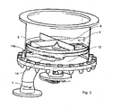
- Fig. 3 shows a further illustration of a device according to the invention. It can be seen here but below the intermediate plate 6 above the bottom plate 12 arranged displacement device 14. This displacement device rotates in any case with respect to the bottom plate 12. Preferably, the rotational movement of this displacement device 14 is synchronized or coupled with the rotational movement of the intermediate plate 6.
- this displacement device 14 By means of this displacement device 14, the bulk material fallen onto the bottom plate 12 is displaced relative to the bottom plate 12 and finally forced to an outlet opening (not shown), through which it can fall.
- This outlet is at the in Fig. 3 shown embodiment provided behind the displacement device 14.
- this outlet opening has a circular profile.
- the displacement device 14 is at least slightly spaced from the bottom plate 12. However, it would also be possible to provide more than one such displacement device. It can be seen that the displacement device has a curvature 14a, which is designed so that during the rotation of the displacement device 14 counter to the clockwise direction, the bulk material is forced into this curvature. Below this curvature is at a predetermined rotational position of the displacement device exactly the opening in the bottom plate 12. In this way, a particularly efficient discharge of the bulk material through the bottom plate 12 is achieved.
- this curvature 14a is adapted to the opening cross-section of the discharge opening and the above-mentioned distance of the displacement device or of the rake is here again dependent on the bulk material.
- this distance relative to the bottom plate is changeable. In this way, a crushing or grinding of the bulk material is prevented and thus spared the product.
Landscapes
- Engineering & Computer Science (AREA)
- Mechanical Engineering (AREA)
- Environmental & Geological Engineering (AREA)
- Chemical & Material Sciences (AREA)
- Organic Chemistry (AREA)
- Chemical Kinetics & Catalysis (AREA)
- Filling Or Emptying Of Bunkers, Hoppers, And Tanks (AREA)
- Formation And Processing Of Food Products (AREA)
- Combined Means For Separation Of Solids (AREA)
- Manufacturing Of Electric Cables (AREA)
- Control And Other Processes For Unpacking Of Materials (AREA)
- Air Transport Of Granular Materials (AREA)
- Threshing Machine Elements (AREA)
- Processes Of Treating Macromolecular Substances (AREA)
Claims (13)
- Dispositif (1) pour le déversement de produit en vrac, avec un réservoir (2) où le produit en vrac peut être versé, avec une grille (4) de répartition disposée dans le réservoir (2) et une plaque (6) intercalaire disposée sous la grille (4) de répartition, ladite plaque intercalaire (6) comportant une ouverture (5) de passage pour le produit en vrac, ainsi qu'une ouverture prévue sous la plaque (6) intercalaire, par laquelle le produit en vrac peut être prélevé du réservoir (2), caractérisé en ce que la plaque (6) intercalaire est rotative par rapport à la grille (4) de répartition et la grille (4) de répartition fixe par rapport au réservoir (2).
- Dispositif (1) selon la revendication 1, caractérisé en ce qu'une plaque (12) de fond fixe par rapport au réservoir (2) est prévue en dessous de la plaque (6) intercalaire, et en ce que l'ouverture (8) est prévue dans ladite plaque (12) de fond.
- Dispositif (1) selon la revendication 2, caractérisé en ce qu'un mécanisme (14) de déplacement rotatif par rapport au réservoir (2) est prévu au-dessus de la plaque (12) de fond, lequel déplace le produit en vrac par rapport à la plaque (12) de fond.
- Dispositif (1) selon la revendication 3, caractérisé en ce que le mécanisme (14) de déplacement présente une courbure (14a) ajustée à la section de l'ouverture.
- Dispositif (1) selon au moins une des revendications précédentes, caractérisé en ce que l'ouverture (5) de passage est une fente s'étendant dans une direction radiale de la plaque (6) intercalaire.
- Dispositif (1) selon au moins une des revendications précédentes, caractérisé en ce que la plaque (6) intercalaire présente un biseau (9) devant l'ouverture (5) de passage dans la direction de rotation, lequel recouvre l'ouverture (5) de passage située sous ledit biseau (9).
- Dispositif (1) selon au moins une des revendications précédentes, caractérisé en ce que le dispositif (1) comporte un mécanisme d'entraînement qui entraîne la plaque (6) intercalaire, et en ce que ledit mécanisme (20) d'entraînement est prévu en dessous du réservoir (2).
- Dispositif (1) selon au moins une des revendications précédentes, caractérisé en ce que la grille de répartition comporte entre 3 et 12, avantageusement entre 4 et 10 et préférentiellement entre 4 et 8 bras (8) s'étendant dans une direction radiale de la plaque (6) intercalaire.
- Dispositif (1) selon au moins une des revendications précédentes, caractérisé en ce que la grille (4) de répartition est espacée de la plaque (6) intercalaire.
- Dispositif (1) selon au moins une des revendications précédentes, caractérisé en ce que le dispositif (1) comporte un corps (22) de répartition conique disposé centralement au-dessus de la plaque (6) intercalaire.
- Procédé de déversement de produit en vrac hors d'un réservoir (2), comportant les étapes :- de remplissage du réservoir (2) avec le produit en vrac, ledit produit en vrac étant versé par en haut sur une plaque (6) intercalaire en rotation par rapport à une grille (4) de répartition disposée au-dessus de la plaque (6) intercalaire ;- de passage du produit en vrac par au moins une ouverture (5) prévue dans la plaque (6) intercalaire ;- d'évacuation du produit en vrac hors du réservoir (2) par une ouverture prévue en-dessous de la plaque (6) intercalaire, caractérisé en ce que la grille (4) de répartition est immobile par rapport au réservoir (2) et en ce que la plaque (6) intercalaire est mobile par rapport au réservoir (2).
- Procédé selon la revendication 11, caractérisé en ce que le produit en vrac tombe sur une plaque (12) de fond en-dessous de la plaque (6) intercalaire.
- Procédé selon la revendication 12, caractérisé en ce que le produit en vrac est déplacé par rapport à la plaque (12) de fond au moyen d'un mécanisme (14) de déplacement.
Priority Applications (1)
| Application Number | Priority Date | Filing Date | Title |
|---|---|---|---|
| PL08166994T PL2050552T3 (pl) | 2007-10-18 | 2008-10-20 | Urządzenie do wyładunku materiału sypkiego |
Applications Claiming Priority (1)
| Application Number | Priority Date | Filing Date | Title |
|---|---|---|---|
| DE200710050315 DE102007050315A1 (de) | 2007-10-18 | 2007-10-18 | Vorrichtung zum Austragen von Schüttgut |
Publications (2)
| Publication Number | Publication Date |
|---|---|
| EP2050552A1 EP2050552A1 (fr) | 2009-04-22 |
| EP2050552B1 true EP2050552B1 (fr) | 2010-04-21 |
Family
ID=40276116
Family Applications (1)
| Application Number | Title | Priority Date | Filing Date |
|---|---|---|---|
| EP20080166994 Active EP2050552B1 (fr) | 2007-10-18 | 2008-10-20 | Dispositif de sortie de produits en vrac |
Country Status (8)
| Country | Link |
|---|---|
| US (1) | US8104645B2 (fr) |
| EP (1) | EP2050552B1 (fr) |
| CN (1) | CN101417754B (fr) |
| AT (1) | ATE464991T1 (fr) |
| BR (1) | BRPI0804351B1 (fr) |
| DE (2) | DE102007050315A1 (fr) |
| ES (1) | ES2347848T3 (fr) |
| PL (1) | PL2050552T3 (fr) |
Families Citing this family (11)
| Publication number | Priority date | Publication date | Assignee | Title |
|---|---|---|---|---|
| CN104373655A (zh) * | 2014-10-16 | 2015-02-25 | 浙江东立绿源科技股份有限公司 | 一种自动化闭合型加料阀门 |
| CN104971892A (zh) * | 2015-07-12 | 2015-10-14 | 安徽捷迅光电技术有限公司 | 不规则颗粒分选机 |
| CN105499112B (zh) * | 2016-01-21 | 2017-10-13 | 吴剑辉 | 一种制药用筛分装置 |
| CN105966936A (zh) * | 2016-06-29 | 2016-09-28 | 温州市朴红农业科技有限公司 | 一种粉料下料装置 |
| US10994305B2 (en) * | 2018-02-07 | 2021-05-04 | David Lee Rahamin | Devices and methods for sifting |
| CN108502335B (zh) * | 2018-04-17 | 2023-08-15 | 深圳贝仕达克技术股份有限公司 | 智能存储装置 |
| RU2705779C1 (ru) * | 2019-05-14 | 2019-11-11 | Федеральное государственное бюджетное образовательное учреждение высшего образования "Российский государственный аграрный университет - МСХА имени К.А. Тимирязева" (ФГБОУ ВО РГАУ - МСХА имени К.А. Тимирязева) | Малогабаритный комбикормовый агрегат |
| CN113244858B (zh) * | 2021-07-02 | 2021-09-14 | 东营科宏化工有限公司 | 一种烷基苯酚制备用催化剂的计量装置 |
| CN115254573B (zh) * | 2022-07-18 | 2023-08-04 | 湖南道生新材料有限公司 | 一种涂料粉末研磨用分选剔除装置 |
| CN115646352A (zh) * | 2022-10-19 | 2023-01-31 | 江苏福亿自动化设备有限公司 | 一种带内部除尘的辊压干法造粒设备 |
| CN116603456A (zh) * | 2023-07-06 | 2023-08-18 | 江苏南大光电材料股份有限公司 | 用于固体原料的加料装置 |
Family Cites Families (19)
| Publication number | Priority date | Publication date | Assignee | Title |
|---|---|---|---|---|
| US1668825A (en) * | 1925-11-28 | 1928-05-08 | Sobek Emanuel | Discharge funnel for silos |
| US2672075A (en) * | 1949-03-23 | 1954-03-16 | Fraser Douglas | Machine for treating paper mill waste |
| US2592676A (en) * | 1949-04-23 | 1952-04-15 | Cecile Franklin | Sand urn |
| US2877937A (en) * | 1957-11-01 | 1959-03-17 | Gordon E Weir | Measuring dispenser |
| US3260415A (en) * | 1964-07-13 | 1966-07-12 | Takeda Chemical Industries Ltd | Particulate solid material discharge apparatus |
| US3893592A (en) * | 1973-10-29 | 1975-07-08 | Louis T Friedman | Measuring and dispensing apparatus |
| DE2400547C3 (de) * | 1974-01-07 | 1978-06-29 | Saxlund Geb. Westerhus-Erichsen, Astrid Alice, 3040 Soltau | Bunker mit Austragvorrichtung |
| DE2519773A1 (de) | 1975-05-02 | 1976-11-11 | Buehler Miag Gmbh | Einschuettgosse fuer schuettgut |
| JPS592027Y2 (ja) | 1979-07-02 | 1984-01-20 | 株式会社 松下産業 | 縦型ロ−タリバルブ |
| JPS5889523A (ja) | 1981-11-17 | 1983-05-27 | Sumitomo Metal Ind Ltd | 粉体の分配輸送方法及び装置 |
| US4543181A (en) * | 1982-12-16 | 1985-09-24 | Kamyr, Inc. | Medium consistency flat disk pressure screen |
| JPS6118642A (ja) | 1984-07-04 | 1986-01-27 | Kubota Ltd | 粉粒体供給装置 |
| DE3626003A1 (de) | 1986-07-31 | 1988-02-11 | Hans Juergen Dipl Ing Meyer | Silo fuer schuettgut |
| SU1662911A2 (ru) * | 1986-08-29 | 1991-07-15 | Институт Горного Дела Со Ан Ссср | Дозатор сыпучих материалов |
| DE3942558A1 (de) * | 1989-12-22 | 1991-06-27 | Schwedes Joerg | Silo mit einer austragvorrichtung |
| US5360141A (en) * | 1991-04-08 | 1994-11-01 | Tecnorama S.R.L. | Device for metering powder, grained or micropearl dyeing materials |
| CN2143866Y (zh) * | 1992-12-29 | 1993-10-20 | 新疆农业科学院农业机械化研究所 | 葡萄干脱粒清选机 |
| DE19953659A1 (de) | 1999-11-08 | 2001-05-10 | Buehler Ag | Verfahren und Vorrichtung zur Dekontamination von Polykondensaten |
| CN2875033Y (zh) * | 2006-01-17 | 2007-03-07 | 张齐山 | 人力、动力两用打谷机 |
-
2007
- 2007-10-18 DE DE200710050315 patent/DE102007050315A1/de not_active Withdrawn
-
2008
- 2008-10-16 BR BRPI0804351A patent/BRPI0804351B1/pt active IP Right Grant
- 2008-10-17 US US12/288,270 patent/US8104645B2/en active Active
- 2008-10-20 ES ES08166994T patent/ES2347848T3/es active Active
- 2008-10-20 EP EP20080166994 patent/EP2050552B1/fr active Active
- 2008-10-20 AT AT08166994T patent/ATE464991T1/de active
- 2008-10-20 DE DE200850000559 patent/DE502008000559D1/de active Active
- 2008-10-20 PL PL08166994T patent/PL2050552T3/pl unknown
- 2008-10-20 CN CN2008101706717A patent/CN101417754B/zh active Active
Also Published As
| Publication number | Publication date |
|---|---|
| US8104645B2 (en) | 2012-01-31 |
| DE502008000559D1 (de) | 2010-06-02 |
| CN101417754B (zh) | 2013-06-05 |
| ES2347848T3 (es) | 2010-11-04 |
| CN101417754A (zh) | 2009-04-29 |
| BRPI0804351A2 (pt) | 2009-10-06 |
| EP2050552A1 (fr) | 2009-04-22 |
| PL2050552T3 (pl) | 2010-11-30 |
| US20090107894A1 (en) | 2009-04-30 |
| ATE464991T1 (de) | 2010-05-15 |
| BRPI0804351B1 (pt) | 2017-04-04 |
| DE102007050315A1 (de) | 2009-04-23 |
Similar Documents
| Publication | Publication Date | Title |
|---|---|---|
| EP2050552B1 (fr) | Dispositif de sortie de produits en vrac | |
| DE102011112016B3 (de) | Verfahren zum Reinigen von Dosiervorrichtungen, die zum Beschicken von Vorrichtungen - zum Beispiel Extruder, Spritzgussmaschinen oder dergleichen - mit Schüttgütern - Pellets, Spänen, Granulaten, Pulvern, Flakes, Körnen, Mehl oder dergleichen - dienen, und Vorrichtung zur Durchführung eines derartigen Verfahrens und Steuerung für die Reinigung einer derartigen Dosiervorrichtung | |
| DE102005046207B4 (de) | Vorrichtung zum Zerkleinern von Haufwerk | |
| EP0003779B1 (fr) | Appareil de traitement et de broyage | |
| EP4168168B1 (fr) | Silo de mélange pour matériau en vrac, installation de production dotée d'un tel silo de mélange, et procédé de fonctionnement d'un tel silo de mélange | |
| EP1570919B1 (fr) | Appareil pour la séparation de matériaux substantiellement solides | |
| WO2016177358A1 (fr) | Broyeuse comprenant un système de rotor et procédé servant au broyage d'un produit chargé | |
| DE1285421B (de) | Trommel zum Aufbereiten von Muell | |
| EP0588838B1 (fr) | Dispositif d'ebavurage et de depoussierage de comprimes ou de pillules | |
| EP2564694A1 (fr) | Dispositif dýacheminement | |
| CH667597A5 (de) | Verfahren zum mischen von schuettbaren materialien mit einstellbarem mischungsverhaeltnis. | |
| EP2393598B1 (fr) | Dispositif de broyage de matière plastique | |
| CH660073A5 (de) | Vakuum-trocken-vorrichtung. | |
| WO2012084734A1 (fr) | Dispositif d'aspiration et procédé pour extraire de la matière en vrac d'un contenant | |
| EP3423203B1 (fr) | Dispositif et procédé pour l'introduction simultanée de particules de matériau synthétique et d'un liquide dans un dispositif de nettoyage | |
| DE102011119615A1 (de) | Klumpenbrecher und Verfahren zum Brechen von in einem Schüttgutstrom enthaltenen Klumpen | |
| EP2075107B1 (fr) | Procédé et dispositif destinés à la préparation de déchets en plastique | |
| EP3691799B1 (fr) | Dispositif de tamisage | |
| DE1288888B (de) | Vorrichtung zum Mahlen von stueckigem Gut | |
| EP1904236A1 (fr) | Dispositif de comminution comportant plusieurs arbres rotatifs ou oscillants, essentiellement paralleles, entraines par moteur | |
| EP2203254B1 (fr) | Broyeur vibrant et procédé de nettoyage de broyeurs vibrants | |
| DE102011050900B3 (de) | Vorrichtung zum Einblasen von Dämmstoffen und eine hierfür bestimmte Aufflockeinheit | |
| WO2006010475A1 (fr) | Systeme de dosage et/ou de remplissage destine a des produits en vrac fluides | |
| DE3105075A1 (de) | "zuteiler fuer eine mischung mit heterogener konsistenz" | |
| EP1698732B1 (fr) | Dispositif mobile compact de traitement de sols |
Legal Events
| Date | Code | Title | Description |
|---|---|---|---|
| PUAI | Public reference made under article 153(3) epc to a published international application that has entered the european phase |
Free format text: ORIGINAL CODE: 0009012 |
|
| AK | Designated contracting states |
Kind code of ref document: A1 Designated state(s): AT BE BG CH CY CZ DE DK EE ES FI FR GB GR HR HU IE IS IT LI LT LU LV MC MT NL NO PL PT RO SE SI SK TR |
|
| AX | Request for extension of the european patent |
Extension state: AL BA MK RS |
|
| GRAP | Despatch of communication of intention to grant a patent |
Free format text: ORIGINAL CODE: EPIDOSNIGR1 |
|
| 17P | Request for examination filed |
Effective date: 20090902 |
|
| AKX | Designation fees paid |
Designated state(s): AT BE BG CH CY CZ DE DK EE ES FI FR GB GR HR HU IE IS IT LI LT LU LV MC MT NL NO PL PT RO SE SI SK TR |
|
| GRAS | Grant fee paid |
Free format text: ORIGINAL CODE: EPIDOSNIGR3 |
|
| GRAA | (expected) grant |
Free format text: ORIGINAL CODE: 0009210 |
|
| AK | Designated contracting states |
Kind code of ref document: B1 Designated state(s): AT BE BG CH CY CZ DE DK EE ES FI FR GB GR HR HU IE IS IT LI LT LU LV MC MT NL NO PL PT RO SE SI SK TR |
|
| REG | Reference to a national code |
Ref country code: GB Ref legal event code: FG4D Free format text: NOT ENGLISH |
|
| REG | Reference to a national code |
Ref country code: CH Ref legal event code: EP |
|
| REG | Reference to a national code |
Ref country code: IE Ref legal event code: FG4D Free format text: LANGUAGE OF EP DOCUMENT: GERMAN |
|
| REF | Corresponds to: |
Ref document number: 502008000559 Country of ref document: DE Date of ref document: 20100602 Kind code of ref document: P |
|
| REG | Reference to a national code |
Ref country code: NL Ref legal event code: T3 |
|
| REG | Reference to a national code |
Ref country code: CH Ref legal event code: NV Representative=s name: ROTTMANN, ZIMMERMANN + PARTNER AG |
|
| REG | Reference to a national code |
Ref country code: GR Ref legal event code: EP Ref document number: 20100401746 Country of ref document: GR |
|
| LTIE | Lt: invalidation of european patent or patent extension |
Effective date: 20100421 |
|
| PG25 | Lapsed in a contracting state [announced via postgrant information from national office to epo] |
Ref country code: SE Free format text: LAPSE BECAUSE OF FAILURE TO SUBMIT A TRANSLATION OF THE DESCRIPTION OR TO PAY THE FEE WITHIN THE PRESCRIBED TIME-LIMIT Effective date: 20100421 Ref country code: NO Free format text: LAPSE BECAUSE OF FAILURE TO SUBMIT A TRANSLATION OF THE DESCRIPTION OR TO PAY THE FEE WITHIN THE PRESCRIBED TIME-LIMIT Effective date: 20100721 Ref country code: LT Free format text: LAPSE BECAUSE OF FAILURE TO SUBMIT A TRANSLATION OF THE DESCRIPTION OR TO PAY THE FEE WITHIN THE PRESCRIBED TIME-LIMIT Effective date: 20100421 |
|
| REG | Reference to a national code |
Ref country code: ES Ref legal event code: FG2A Ref document number: 2347848 Country of ref document: ES Kind code of ref document: T3 |
|
| REG | Reference to a national code |
Ref country code: IE Ref legal event code: FD4D |
|
| PG25 | Lapsed in a contracting state [announced via postgrant information from national office to epo] |
Ref country code: SI Free format text: LAPSE BECAUSE OF FAILURE TO SUBMIT A TRANSLATION OF THE DESCRIPTION OR TO PAY THE FEE WITHIN THE PRESCRIBED TIME-LIMIT Effective date: 20100421 Ref country code: LV Free format text: LAPSE BECAUSE OF FAILURE TO SUBMIT A TRANSLATION OF THE DESCRIPTION OR TO PAY THE FEE WITHIN THE PRESCRIBED TIME-LIMIT Effective date: 20100421 Ref country code: IS Free format text: LAPSE BECAUSE OF FAILURE TO SUBMIT A TRANSLATION OF THE DESCRIPTION OR TO PAY THE FEE WITHIN THE PRESCRIBED TIME-LIMIT Effective date: 20100821 Ref country code: HR Free format text: LAPSE BECAUSE OF FAILURE TO SUBMIT A TRANSLATION OF THE DESCRIPTION OR TO PAY THE FEE WITHIN THE PRESCRIBED TIME-LIMIT Effective date: 20100421 Ref country code: FI Free format text: LAPSE BECAUSE OF FAILURE TO SUBMIT A TRANSLATION OF THE DESCRIPTION OR TO PAY THE FEE WITHIN THE PRESCRIBED TIME-LIMIT Effective date: 20100421 |
|
| REG | Reference to a national code |
Ref country code: PL Ref legal event code: T3 |
|
| PG25 | Lapsed in a contracting state [announced via postgrant information from national office to epo] |
Ref country code: CY Free format text: LAPSE BECAUSE OF FAILURE TO SUBMIT A TRANSLATION OF THE DESCRIPTION OR TO PAY THE FEE WITHIN THE PRESCRIBED TIME-LIMIT Effective date: 20100609 |
|
| PG25 | Lapsed in a contracting state [announced via postgrant information from national office to epo] |
Ref country code: EE Free format text: LAPSE BECAUSE OF FAILURE TO SUBMIT A TRANSLATION OF THE DESCRIPTION OR TO PAY THE FEE WITHIN THE PRESCRIBED TIME-LIMIT Effective date: 20100421 Ref country code: DK Free format text: LAPSE BECAUSE OF FAILURE TO SUBMIT A TRANSLATION OF THE DESCRIPTION OR TO PAY THE FEE WITHIN THE PRESCRIBED TIME-LIMIT Effective date: 20100421 Ref country code: IE Free format text: LAPSE BECAUSE OF FAILURE TO SUBMIT A TRANSLATION OF THE DESCRIPTION OR TO PAY THE FEE WITHIN THE PRESCRIBED TIME-LIMIT Effective date: 20100421 |
|
| PLBE | No opposition filed within time limit |
Free format text: ORIGINAL CODE: 0009261 |
|
| STAA | Information on the status of an ep patent application or granted ep patent |
Free format text: STATUS: NO OPPOSITION FILED WITHIN TIME LIMIT |
|
| PG25 | Lapsed in a contracting state [announced via postgrant information from national office to epo] |
Ref country code: RO Free format text: LAPSE BECAUSE OF FAILURE TO SUBMIT A TRANSLATION OF THE DESCRIPTION OR TO PAY THE FEE WITHIN THE PRESCRIBED TIME-LIMIT Effective date: 20100421 Ref country code: SK Free format text: LAPSE BECAUSE OF FAILURE TO SUBMIT A TRANSLATION OF THE DESCRIPTION OR TO PAY THE FEE WITHIN THE PRESCRIBED TIME-LIMIT Effective date: 20100421 |
|
| 26N | No opposition filed |
Effective date: 20110124 |
|
| PG25 | Lapsed in a contracting state [announced via postgrant information from national office to epo] |
Ref country code: MC Free format text: LAPSE BECAUSE OF NON-PAYMENT OF DUE FEES Effective date: 20101031 |
|
| REG | Reference to a national code |
Ref country code: CH Ref legal event code: PFA Owner name: KRONES AG Free format text: KRONES AG#BOEHMERWALDSTRASSE 5#93073 NEUTRAUBLING (DE) -TRANSFER TO- KRONES AG#BOEHMERWALDSTRASSE 5#93073 NEUTRAUBLING (DE) |
|
| PG25 | Lapsed in a contracting state [announced via postgrant information from national office to epo] |
Ref country code: MT Free format text: LAPSE BECAUSE OF FAILURE TO SUBMIT A TRANSLATION OF THE DESCRIPTION OR TO PAY THE FEE WITHIN THE PRESCRIBED TIME-LIMIT Effective date: 20100421 |
|
| PG25 | Lapsed in a contracting state [announced via postgrant information from national office to epo] |
Ref country code: BG Free format text: LAPSE BECAUSE OF FAILURE TO SUBMIT A TRANSLATION OF THE DESCRIPTION OR TO PAY THE FEE WITHIN THE PRESCRIBED TIME-LIMIT Effective date: 20100421 Ref country code: HU Free format text: LAPSE BECAUSE OF FAILURE TO SUBMIT A TRANSLATION OF THE DESCRIPTION OR TO PAY THE FEE WITHIN THE PRESCRIBED TIME-LIMIT Effective date: 20101022 Ref country code: LU Free format text: LAPSE BECAUSE OF NON-PAYMENT OF DUE FEES Effective date: 20101020 |
|
| PG25 | Lapsed in a contracting state [announced via postgrant information from national office to epo] |
Ref country code: TR Free format text: LAPSE BECAUSE OF FAILURE TO SUBMIT A TRANSLATION OF THE DESCRIPTION OR TO PAY THE FEE WITHIN THE PRESCRIBED TIME-LIMIT Effective date: 20100421 |
|
| GBPC | Gb: european patent ceased through non-payment of renewal fee |
Effective date: 20121020 |
|
| PG25 | Lapsed in a contracting state [announced via postgrant information from national office to epo] |
Ref country code: GB Free format text: LAPSE BECAUSE OF NON-PAYMENT OF DUE FEES Effective date: 20121020 Ref country code: PT Free format text: LAPSE BECAUSE OF NON-PAYMENT OF DUE FEES Effective date: 20100421 |
|
| PG25 | Lapsed in a contracting state [announced via postgrant information from national office to epo] |
Ref country code: BG Free format text: LAPSE BECAUSE OF FAILURE TO SUBMIT A TRANSLATION OF THE DESCRIPTION OR TO PAY THE FEE WITHIN THE PRESCRIBED TIME-LIMIT Effective date: 20100721 |
|
| PGFP | Annual fee paid to national office [announced via postgrant information from national office to epo] |
Ref country code: GR Payment date: 20150915 Year of fee payment: 8 |
|
| PGFP | Annual fee paid to national office [announced via postgrant information from national office to epo] |
Ref country code: BE Payment date: 20151012 Year of fee payment: 8 |
|
| REG | Reference to a national code |
Ref country code: FR Ref legal event code: PLFP Year of fee payment: 9 |
|
| REG | Reference to a national code |
Ref country code: CH Ref legal event code: PCAR Free format text: NEW ADDRESS: GARTENSTRASSE 28 A, 5400 BADEN (CH) |
|
| PG25 | Lapsed in a contracting state [announced via postgrant information from national office to epo] |
Ref country code: BE Free format text: LAPSE BECAUSE OF NON-PAYMENT OF DUE FEES Effective date: 20161031 |
|
| PG25 | Lapsed in a contracting state [announced via postgrant information from national office to epo] |
Ref country code: GR Free format text: LAPSE BECAUSE OF NON-PAYMENT OF DUE FEES Effective date: 20170504 |
|
| REG | Reference to a national code |
Ref country code: FR Ref legal event code: PLFP Year of fee payment: 10 |
|
| REG | Reference to a national code |
Ref country code: BE Ref legal event code: MM Effective date: 20161031 |
|
| REG | Reference to a national code |
Ref country code: FR Ref legal event code: PLFP Year of fee payment: 11 |
|
| P01 | Opt-out of the competence of the unified patent court (upc) registered |
Effective date: 20230523 |
|
| PGFP | Annual fee paid to national office [announced via postgrant information from national office to epo] |
Ref country code: PL Payment date: 20250912 Year of fee payment: 18 Ref country code: NL Payment date: 20250912 Year of fee payment: 18 Ref country code: IT Payment date: 20250922 Year of fee payment: 18 |
|
| PGFP | Annual fee paid to national office [announced via postgrant information from national office to epo] |
Ref country code: FR Payment date: 20250908 Year of fee payment: 18 |
|
| REG | Reference to a national code |
Ref country code: CH Ref legal event code: U11 Free format text: ST27 STATUS EVENT CODE: U-0-0-U10-U11 (AS PROVIDED BY THE NATIONAL OFFICE) Effective date: 20251101 |
|
| PGFP | Annual fee paid to national office [announced via postgrant information from national office to epo] |
Ref country code: DE Payment date: 20250902 Year of fee payment: 18 |
|
| PGFP | Annual fee paid to national office [announced via postgrant information from national office to epo] |
Ref country code: AT Payment date: 20250925 Year of fee payment: 18 |
|
| PGFP | Annual fee paid to national office [announced via postgrant information from national office to epo] |
Ref country code: CH Payment date: 20251101 Year of fee payment: 18 |
|
| PGFP | Annual fee paid to national office [announced via postgrant information from national office to epo] |
Ref country code: CZ Payment date: 20251006 Year of fee payment: 18 |
|
| PGFP | Annual fee paid to national office [announced via postgrant information from national office to epo] |
Ref country code: ES Payment date: 20251105 Year of fee payment: 18 |
|
| REG | Reference to a national code |
Ref country code: CH Ref legal event code: R17 Free format text: ST27 STATUS EVENT CODE: U-0-0-R10-R17 (AS PROVIDED BY THE NATIONAL OFFICE) Effective date: 20260410 |