EP2393598B1 - Dispositif de broyage de matière plastique - Google Patents
Dispositif de broyage de matière plastique Download PDFInfo
- Publication number
- EP2393598B1 EP2393598B1 EP10701493.8A EP10701493A EP2393598B1 EP 2393598 B1 EP2393598 B1 EP 2393598B1 EP 10701493 A EP10701493 A EP 10701493A EP 2393598 B1 EP2393598 B1 EP 2393598B1
- Authority
- EP
- European Patent Office
- Prior art keywords
- air
- rotor body
- container
- plastic
- knives
- Prior art date
- Legal status (The legal status is an assumption and is not a legal conclusion. Google has not performed a legal analysis and makes no representation as to the accuracy of the status listed.)
- Active
Links
- 239000004033 plastic Substances 0.000 title description 71
- 229920003023 plastic Polymers 0.000 title description 71
- 229920001169 thermoplastic Polymers 0.000 claims description 9
- 239000004416 thermosoftening plastic Substances 0.000 claims description 9
- 230000000694 effects Effects 0.000 claims description 6
- 238000005549 size reduction Methods 0.000 claims 5
- 239000000463 material Substances 0.000 description 61
- 239000013502 plastic waste Substances 0.000 description 19
- 238000001035 drying Methods 0.000 description 11
- 239000002699 waste material Substances 0.000 description 11
- 238000005520 cutting process Methods 0.000 description 9
- 238000002156 mixing Methods 0.000 description 7
- 239000002245 particle Substances 0.000 description 6
- 238000011049 filling Methods 0.000 description 5
- 239000012815 thermoplastic material Substances 0.000 description 5
- 238000000034 method Methods 0.000 description 4
- 238000012545 processing Methods 0.000 description 4
- 230000015572 biosynthetic process Effects 0.000 description 3
- 238000013461 design Methods 0.000 description 3
- 238000012423 maintenance Methods 0.000 description 3
- 238000004064 recycling Methods 0.000 description 3
- 239000004698 Polyethylene Substances 0.000 description 2
- 239000004743 Polypropylene Substances 0.000 description 2
- 238000007906 compression Methods 0.000 description 2
- 238000011109 contamination Methods 0.000 description 2
- 230000006378 damage Effects 0.000 description 2
- 238000005265 energy consumption Methods 0.000 description 2
- 238000004519 manufacturing process Methods 0.000 description 2
- 230000002093 peripheral effect Effects 0.000 description 2
- -1 polyethylene Polymers 0.000 description 2
- 238000010008 shearing Methods 0.000 description 2
- OKTJSMMVPCPJKN-UHFFFAOYSA-N Carbon Chemical compound [C] OKTJSMMVPCPJKN-UHFFFAOYSA-N 0.000 description 1
- 239000004793 Polystyrene Substances 0.000 description 1
- 208000007536 Thrombosis Diseases 0.000 description 1
- 208000027418 Wounds and injury Diseases 0.000 description 1
- 230000001174 ascending effect Effects 0.000 description 1
- 238000007664 blowing Methods 0.000 description 1
- 229910052799 carbon Inorganic materials 0.000 description 1
- 238000006243 chemical reaction Methods 0.000 description 1
- 238000005056 compaction Methods 0.000 description 1
- 230000006835 compression Effects 0.000 description 1
- 238000009833 condensation Methods 0.000 description 1
- 230000005494 condensation Effects 0.000 description 1
- 238000010276 construction Methods 0.000 description 1
- 238000000280 densification Methods 0.000 description 1
- 230000001419 dependent effect Effects 0.000 description 1
- 238000009826 distribution Methods 0.000 description 1
- 239000000428 dust Substances 0.000 description 1
- 238000000605 extraction Methods 0.000 description 1
- 238000001125 extrusion Methods 0.000 description 1
- 210000001035 gastrointestinal tract Anatomy 0.000 description 1
- 230000005484 gravity Effects 0.000 description 1
- 238000009776 industrial production Methods 0.000 description 1
- 238000001746 injection moulding Methods 0.000 description 1
- 208000014674 injury Diseases 0.000 description 1
- 239000007788 liquid Substances 0.000 description 1
- 238000011068 loading method Methods 0.000 description 1
- 238000005461 lubrication Methods 0.000 description 1
- 230000007257 malfunction Effects 0.000 description 1
- 229910052751 metal Inorganic materials 0.000 description 1
- 239000002184 metal Substances 0.000 description 1
- 150000002739 metals Chemical class 0.000 description 1
- 238000012544 monitoring process Methods 0.000 description 1
- 239000003973 paint Substances 0.000 description 1
- 229920000573 polyethylene Polymers 0.000 description 1
- 229920000098 polyolefin Polymers 0.000 description 1
- 229920001155 polypropylene Polymers 0.000 description 1
- 229920002223 polystyrene Polymers 0.000 description 1
- 239000004800 polyvinyl chloride Substances 0.000 description 1
- 238000004080 punching Methods 0.000 description 1
- 230000000630 rising effect Effects 0.000 description 1
- 238000000926 separation method Methods 0.000 description 1
- 238000005245 sintering Methods 0.000 description 1
- 238000010561 standard procedure Methods 0.000 description 1
- 238000003860 storage Methods 0.000 description 1
- 239000000126 substance Substances 0.000 description 1
- 238000001721 transfer moulding Methods 0.000 description 1
- 238000009423 ventilation Methods 0.000 description 1
- XLYOFNOQVPJJNP-UHFFFAOYSA-N water Substances O XLYOFNOQVPJJNP-UHFFFAOYSA-N 0.000 description 1
- 230000004584 weight gain Effects 0.000 description 1
- 235000019786 weight gain Nutrition 0.000 description 1
Images

Classifications
-
- B—PERFORMING OPERATIONS; TRANSPORTING
- B02—CRUSHING, PULVERISING, OR DISINTEGRATING; PREPARATORY TREATMENT OF GRAIN FOR MILLING
- B02C—CRUSHING, PULVERISING, OR DISINTEGRATING IN GENERAL; MILLING GRAIN
- B02C18/00—Disintegrating by knives or other cutting or tearing members which chop material into fragments
- B02C18/06—Disintegrating by knives or other cutting or tearing members which chop material into fragments with rotating knives
- B02C18/14—Disintegrating by knives or other cutting or tearing members which chop material into fragments with rotating knives within horizontal containers
- B02C18/148—Disintegrating by knives or other cutting or tearing members which chop material into fragments with rotating knives within horizontal containers specially adapted for disintegrating plastics, e.g. cinematographic films
-
- B—PERFORMING OPERATIONS; TRANSPORTING
- B02—CRUSHING, PULVERISING, OR DISINTEGRATING; PREPARATORY TREATMENT OF GRAIN FOR MILLING
- B02C—CRUSHING, PULVERISING, OR DISINTEGRATING IN GENERAL; MILLING GRAIN
- B02C18/00—Disintegrating by knives or other cutting or tearing members which chop material into fragments
- B02C18/06—Disintegrating by knives or other cutting or tearing members which chop material into fragments with rotating knives
- B02C18/16—Details
-
- B—PERFORMING OPERATIONS; TRANSPORTING
- B02—CRUSHING, PULVERISING, OR DISINTEGRATING; PREPARATORY TREATMENT OF GRAIN FOR MILLING
- B02C—CRUSHING, PULVERISING, OR DISINTEGRATING IN GENERAL; MILLING GRAIN
- B02C23/00—Auxiliary methods or auxiliary devices or accessories specially adapted for crushing or disintegrating not provided for in preceding groups or not specially adapted to apparatus covered by a single preceding group
- B02C23/18—Adding fluid, other than for crushing or disintegrating by fluid energy
- B02C23/24—Passing gas through crushing or disintegrating zone
- B02C23/26—Passing gas through crushing or disintegrating zone characterised by point of gas entry or exit or by gas flow path
-
- B—PERFORMING OPERATIONS; TRANSPORTING
- B29—WORKING OF PLASTICS; WORKING OF SUBSTANCES IN A PLASTIC STATE IN GENERAL
- B29B—PREPARATION OR PRETREATMENT OF THE MATERIAL TO BE SHAPED; MAKING GRANULES OR PREFORMS; RECOVERY OF PLASTICS OR OTHER CONSTITUENTS OF WASTE MATERIAL CONTAINING PLASTICS
- B29B17/00—Recovery of plastics or other constituents of waste material containing plastics
- B29B17/04—Disintegrating plastics, e.g. by milling
- B29B17/0412—Disintegrating plastics, e.g. by milling to large particles, e.g. beads, granules, flakes, slices
-
- B—PERFORMING OPERATIONS; TRANSPORTING
- B29—WORKING OF PLASTICS; WORKING OF SUBSTANCES IN A PLASTIC STATE IN GENERAL
- B29K—INDEXING SCHEME ASSOCIATED WITH SUBCLASSES B29B, B29C OR B29D, RELATING TO MOULDING MATERIALS OR TO MATERIALS FOR MOULDS, REINFORCEMENTS, FILLERS OR PREFORMED PARTS, e.g. INSERTS
- B29K2023/00—Use of polyalkenes or derivatives thereof as moulding material
- B29K2023/04—Polymers of ethylene
- B29K2023/06—PE, i.e. polyethylene
-
- B—PERFORMING OPERATIONS; TRANSPORTING
- B29—WORKING OF PLASTICS; WORKING OF SUBSTANCES IN A PLASTIC STATE IN GENERAL
- B29K—INDEXING SCHEME ASSOCIATED WITH SUBCLASSES B29B, B29C OR B29D, RELATING TO MOULDING MATERIALS OR TO MATERIALS FOR MOULDS, REINFORCEMENTS, FILLERS OR PREFORMED PARTS, e.g. INSERTS
- B29K2023/00—Use of polyalkenes or derivatives thereof as moulding material
- B29K2023/10—Polymers of propylene
- B29K2023/12—PP, i.e. polypropylene
-
- B—PERFORMING OPERATIONS; TRANSPORTING
- B29—WORKING OF PLASTICS; WORKING OF SUBSTANCES IN A PLASTIC STATE IN GENERAL
- B29K—INDEXING SCHEME ASSOCIATED WITH SUBCLASSES B29B, B29C OR B29D, RELATING TO MOULDING MATERIALS OR TO MATERIALS FOR MOULDS, REINFORCEMENTS, FILLERS OR PREFORMED PARTS, e.g. INSERTS
- B29K2027/00—Use of polyvinylhalogenides or derivatives thereof as moulding material
- B29K2027/06—PVC, i.e. polyvinylchloride
-
- Y—GENERAL TAGGING OF NEW TECHNOLOGICAL DEVELOPMENTS; GENERAL TAGGING OF CROSS-SECTIONAL TECHNOLOGIES SPANNING OVER SEVERAL SECTIONS OF THE IPC; TECHNICAL SUBJECTS COVERED BY FORMER USPC CROSS-REFERENCE ART COLLECTIONS [XRACs] AND DIGESTS
- Y02—TECHNOLOGIES OR APPLICATIONS FOR MITIGATION OR ADAPTATION AGAINST CLIMATE CHANGE
- Y02W—CLIMATE CHANGE MITIGATION TECHNOLOGIES RELATED TO WASTEWATER TREATMENT OR WASTE MANAGEMENT
- Y02W30/00—Technologies for solid waste management
- Y02W30/50—Reuse, recycling or recovery technologies
- Y02W30/62—Plastics recycling; Rubber recycling
Definitions
- the invention relates to a device for comminution of thermoplastic material comprising a container for receiving the, in particular loosely packed, plastic material and a crushing device projecting into the container or for comminuting the Kunststoffguts and its promotion to a discharge, with the features of the preamble of claim 1.
- Plastic waste varies according to its origin and purity. A distinction is made between production and so-called “post-consumer” waste and between clean, single-grade and mixed, polluted plastic waste.
- plastic waste Before plastic waste can be sent to the actual recycling, it must be pure. For this they are, for example, in the individual fractions polyolefins (as representatives here are called polyethylene PE and polypropylene PP), polyvinyl chloride (PVC) and polystyrene separated and there are adhering foreign substances, such as metals or paints usually removed by physical processes.
- the sorted plastic waste is usually then cleaned with water and then processed by standard methods of plastics processing. These methods include e.g. Extrusion, injection molding or transfer molding, intrusion and sintering processes.
- a device for drying plastic particles which uses a rotary body with a perforated shell, wherein the space expands from the inlet opening of the wet plastic waste to the discharge of the material.
- the plastic waste to be dried is introduced frontally at the smaller end of the rotary body or the perforated shell, wherein the material is thrown in between the rotary body and the perforated jacket existing annular gap against the inner surface of the perforated shell.
- a fan for example in the form of a wing rotating about the axis of the rotary body, is mounted inside the rotary body.
- a disadvantage of this design is that the entire material to be dried in the centrifuge with high energy input must be accelerated and is inevitably compressed. To loosen the plastic waste in order to allow further promotion, the good finally arrives at the lower end to a radial fan, which detects the dried material and expels it through Ausblassstutzen from the device.
- the radial blower is, however, very heavily stressed, it must therefore be carried out particularly thick-walled and also to reduce the resulting noise. Thus, in the blower of this device additional heavy masses must be driven continuously with high energy consumption. A shredding of the plastic waste does not take place or only slightly.
- the DE 92 02 161 presents a device for shredding empty plastic oil cans.
- a cutting disc is provided with cutting blades upwardly employed, wherein directly below the cutting disc designed as a strainer basket for the crushed Plastic shreds and at the bottom of a residual oil pan are arranged.
- a hot air blower is provided that communicates through at least one opening with the hopper. The device is operated discontinuously by filling the hopper with empty canisters, then closed the lid of the hopper and then the motor is driven to drive the cutting disc in motion.
- a rotating screen drum is additionally provided within the hopper at a distance from the cutting wheel, wherein the waste charge is set in rotation in the screen drum while the residual oil is removed more intensively than by draining from the plastic waste.
- a disadvantage of this device is that it can not be operated continuously, since here - comparable to an electric coffee grinder - after filling with a batch of material to be shredded a lid must be closed before the cutting tool can be set in motion. It comes in both the simple design, as well as in the version with a rotating screen drum for compacting the shredded plastic shreds, since they are collected collected after several filling cycles the catcher. In addition, such operation is time-consuming and requires increased monitoring and maintenance.
- a continuous further processing of such pretreated waste therefore requires at least one further storage container as a buffer of the individual waste batches and a suitable device so that the compacted plastic shreds are loosened again and can be transported to the subsequent operations.
- the AT 504 854 shows a method and apparatus for the treatment of preferably thermoplastic waste, the apparatus comprising a receptacle at the bottom of a horizontally rotating carrier disk is mounted with attached at its top mixing or cutting tools.
- the waste material is mixed after the filling of these rotating mixing tools in the region of the receptacle and optionally also comminuted or heated.
- the crushed plastic material is conveyed by the rotational action of the lower mixing tools in a discharge opening on the circumference of the receptacle and passes from there on with a screw conveyor to a subsequent plastic extruder.
- openings are provided through which gas is fed into the receiving container, which is intended to accelerate the drying process of, for example, water-moist plastic waste in the receiving container.
- a disadvantage of this device is that it comes during operation in the region of the receptacle, which is above the rotating disc with the mixing tools, to a thrombus formation and thus to a densification of the wet plastic material on the outer walls of the receptacle.
- the injected, rising gas can only insufficiently flow through the moist plastic material in this area, the desired drying is hindered.
- larger plastic parts and difficult to size materials can not be processed without pre-shredding with this device.
- thermoplastic material according to the preamble of claim 1 having the features of the characterizing part of claim 1.
- a device for the comminution of thermoplastic material, comprising a container for receiving the, in particular loosely packed, plastic material and arranged in the container or arranged therein shredding device for crushing the plastic material, and its promotion to a discharge
- shredding device at least one order a horizontal axis of rotation rotatable rotor body comprises, which is equipped on its peripheral surface with knives, preferably in the container near the orbit of the knife rotor body standing knife are arranged, which exert a shear effect on the plastic goods with the blades of the rotor body
- the device air intakes in Having the area of the crushing device and air outlets in the container wall
- the device comprises a rotor body at least partially surrounding the shell wall, which at a distance from the orbit of the Knife of the rotor body is arranged and profiled by grooves or webs, wherein the air inlets are arranged in the shell wall, wherein the air is guided from a compressed air generating device via lines to the
- the device comprises a compressed air generating device whose output to the air inlets of the device connected.
- the task of the compressed air generating device is to provide compressed air in sufficient quantity to produce a convection flow in the interior of the device and thus to achieve the desired drying effect for the moist plastic material.
- the device according to the invention may have a vapor suction device which is connected to the air outlets of the device.
- the moist air or steam is thus reliably removed from the device and directed to the environment. This condensate formation in the device and an undesirable further moistening of the moist plastic material are prevented by the otherwise existing vapor inside the container.
- the compressed air generating device is designed as a side channel compressor.
- Such side channel blowers are suitable for all applications where more pressure is needed than conventional fans can produce.
- the rotating parts of a side channel compressor do not touch the housing, so there is no friction and therefore no lubrication is necessary.
- the compression process is absolutely oil-free and free of carbon dust, contamination of the air does not take place.
- the Dampfabsaug Skewed is designed as a radial fan.
- the device is expediently designed so that the container for receiving the plastic material communicates with the environment.
- the container for receiving the plastic material communicates with the environment.
- the receptacle may be equipped with a cover or the like to prevent discharge of very light plastic particles from the device.
- a cover is provided at least with an opening for the supply of plastic material.
- the device for comminuting the plastic material which protrudes into the receptacle of the device or is arranged therein comprises a rotatable about a rotation axis rotor body which is equipped on its peripheral surface with knives, preferably arranged in the container near the orbit of the blade of the rotor body standing knife are that exert a shearing effect on the plastic goods with the knives of the rotor body.
- a stuffing gate which is moved back and forth regularly, and thus it is ensured that the plastic material is picked up by the rotor body equipped with knives, then passed into the gap between the rotor body and stationary knives, where it is further comminuted by shearing action.
- the rotor of the comminution device is at least partially surrounded by a casing wall, which is arranged at a distance from the orbit of the blades of the rotor body, wherein the air inlets are arranged in the casing wall.
- the gap space around the rotor body starting with the first stationary knife and then delimited in the circumferential direction of the rotor body by the jacket wall, continues and a longer effect of the shear forces on the plastic material and thus an even more efficient comminution is achieved.
- the air inlets in the shell wall supply the shredder with dry air, which absorbs the residual moisture remaining on the plastic material within the shredder and then rises as moist air or vapor in the receptacle.
- the device without buffer container can be connected directly to a subsequent processing unit, such as a continuous plastic extruder.
- Fig. 1 a device according to the invention for crushing plastic waste in a schematic sectional view of the side
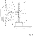
- Fig. 2 a detail of the device in the crushing device in a schematic view from above.
- Fig. 1 the device 1 for comminution of thermoplastic material 2 is shown, comprising a container 3 for receiving the, in particular loosely packed, Kunststoffguts 2 and a projecting into the container 3 or arranged therein shredding device 4 for crushing the plastic material and its promotion to a discharge 5, characterized by air inlets 6 in the crushing device 4 and air outlets 7 in the container wall eighth
- FIG. 1 the device 1 is shown in a sectional view from the side, wherein the selected cutting plane lies vertically in the center of the device 1. This allows a view into the interior of the device 1.
- the moist plastic material 2 passes from the outside by means of a conveyor belt or other, for example, pneumatic conveyor, which in Fig. 1 is not shown and also does not belong to the device 1 according to the invention, through an opening 9 in the container 3 of the device 1.
- the opening 9 is located in the region of the container wall eighth
- the moist plastic material 2 in the container 3 would pass directly in the direction of arrow 10 down to the shredding device 4 and come to lie there close to each other. This would include the residual moisture, which still adheres to the plastic material, included, a drying of the plastic material would be insufficient. Furthermore, the plastics material lying on top of each other would possibly block the gap 11 which is located between the rotor body 12 or the knives 13 fastened thereon, the rotor body 12 rotating in the direction of rotation 14, and the uprights 15, the plastic material 2 thus could not engage in reach the shredder 4 and a trouble-free operation would not be guaranteed.
- the invention is characterized by air inlets 6 in the crushing device 4, in Fig. 1 shown as air inlets 6 in the jacket wall 18, wherein the air from a compressed air generating device 16 is guided via lines to the air inlets 6 and then selectively into the gap 17 between the shell wall 18, which is arranged at a distance from the orbit of the blade 13 of the rotor body 12 is, and the rotor body 12 is injected.
- the air which passes through the air inlets 6 preferably dry in the comminution device 4, guided in the gap 17 mainly in the direction of rotation 14 of the rotor body 12 and thus in the conveying direction of the plastic material 2 and thus 17 moisture is removed from the Kunststoffgut 2 by convection in the gap 17 space Condensate formation on the casing wall 18 and on the rotor body 12 is avoided.
- the compressed air generating device 16 is preferably designed as a side channel compressor 24.
- the main amount of the injected air flows in the direction of rotation 14 along the rotor body 12 through the gap 17 until it at the opposite exit slit 19, which again of one or more stationary knives 15 and on the rotor body 12th attached rotating knives 13 is formed, enters the interior of the container 3.
- a smaller partial flow of the injected air passes contrary to the direction of rotation 14 of the rotor body 12 and thus against the conveying direction of the plastic material 2 within the crushing device 4 through the gap 11 into the interior of the container 3 and thereby possibly loosens in the region of the gap 11 lying Kunststoffgut 2.
- a further smaller partial flow of air blown through the air inlets 6 leaves the gap 17 via the discharge opening 5 and thus passes together with the shredded plastic material in the metering screw 20 and then further into the extruder screw 21, the plastic material for subsequent, in Fig. 1 promotes extruder not shown.
- the air rises from the comminution device 4 in the direction of arrow 22 upwards.
- the flow rate of the air inside the container 3 is selected so that the discontinued plastic material 2 at a low speed in countercurrent in the direction of arrow 10 drops down to the shredder 4 and is dried by the ascending air flow. Very light or flat plastic particles should not be discharged from the container 3.
- a corresponding cover is provided in the region of the opening 9 for the plastic supply, which is designed for example as a fine sieve or flow and adapted to the conveyor, not shown, and the exit of very small plastic particles from the device 1 or through gaps between the device 1 and the conveyor for supplying the plastic material prevented.
- a cover is in Fig. 1 not shown.
- the moist air or steam is discharged in the upper part of the container 3 through air outlets 7 in the container wall 8 out of the device 1 to the environment.
- air outlets 7 are connected to a steam suction device 23.
- the steam extraction device is preferably designed as a radial fan 25, wherein in Fig. 1 two air inlets 7, each with its own radial fan 25 are shown.
- Fig. 1 horizontally in the lower region of the container 3 a stuffing slide 26 is provided. With the help of Stopfschiebers 26, which is moved in the horizontal direction forward and back again, plastic material 2 is reliably supplied to the gap 11. Also shows Fig. 1 the drive 27 of the metering screw 20th
- Fig. 2 shows a detail of the device 1 in the field of crushing device 4 in a schematic sectional view from above.
- the jacket wall 18, which is not here Shown rotor body 12 wrapped, shown with a plurality of air inlets 6.
- the jacket wall 18 is how Fig. 2 shows, profiled by grooves or webs such that the plastic material 2 is pushed together in the gap 17 by the obliquely running grooves or webs in the direction of the centrally disposed discharge opening 5 and from there into the metering screw 20 passes.
- the two screw conveyors 20 and 21 are shown horizontally cut for clarity.
Claims (6)
- Dispositif (1) pour le broyage de matière plastique thermoplastique (2), comprenant un réservoir (3) destiné à contenir la matière plastique, en particulier entassée librement, et un système de broyage (4) pénétrant dans le réservoir ou disposé dans celui-là pour le broyage de la matière plastique, dans lequel le système de broyage (4) comprend au moins un corps de rotor (12) pouvant tourner autour d'un axe de rotation horizontal, qui est équipé de couteaux (13) sur sa surface périphérique, dans lequel des couteaux fixes (15) sont de préférence disposés dans le réservoir (3) à proximité de la trajectoire circulaire des couteaux (13) du corps de rotor (12) et exercent avec les couteaux du corps de rotor un effet de cisaillement sur la matière plastique, dans lequel le dispositif (1) présente des entrées d'air (6) dans la région du système de broyage (4) et des sorties d'air (7) dans la paroi de réservoir (8), et dans lequel le dispositif (1) présente une paroi latérale (18) entourant au moins partiellement le corps de rotor (12), qui est disposée à une distance de la trajectoire circulaire des couteaux (13) du corps de rotor (12) et qui est profilée par des rainures et des nervures, dans lequel les entrées d'air (6) sont disposées dans la paroi latérale (18), dans lequel l'air est conduit depuis un système de production d'air comprimé (16) par des conduites jusqu'aux entrées d'air (6) et dans lequel un guidage de l'air dans la fente (17) est assuré principalement dans la direction de révolution (14) du corps de rotor (12) et dès lors dans la direction de transport de la matière plastique (2), caractérisé en ce que le système de broyage (4) est configuré pour le transport de la matière plastique jusqu'à une ouverture d'extraction (5), dans lequel les rainures ou les nervures font progresser la matière plastique (2) dans la fente (17) en direction de l'ouverture d'extraction (5) lors de la rotation du corps de rotor (12).
- Dispositif (1) selon la revendication 1, caractérisé par un système de production d'air comprimé (16), dont la sortie est raccordée aux entrées d'air (6).
- Dispositif (1) selon une revendication 1 ou 2, caractérisé par un système d'aspiration de vapeur (23) raccordé aux sorties d'air (7).
- Dispositif (1) selon une revendication 2 ou 3, caractérisé en ce que le système de production d'air comprimé (16) est formé par un compresseur à canal latéral (24) et/ou le système d'aspiration de vapeur (23) est formé par une soufflante radiale (25).
- Dispositif (1) selon l'une quelconque des revendications précédentes, caractérisé en ce que le réservoir (3) communique avec l'environnement.
- Dispositif (1) selon l'une quelconque des revendications précédentes, caractérisé en ce qu'un système de transport (20) pour la matière plastique broyée, en particulier une vis de dosage, est raccordé à l'ouverture d'extraction (5).
Priority Applications (1)
| Application Number | Priority Date | Filing Date | Title |
|---|---|---|---|
| PL10701493T PL2393598T3 (pl) | 2009-02-03 | 2010-01-15 | Urządzenie do rozdrabniania tworzyw sztucznych |
Applications Claiming Priority (2)
| Application Number | Priority Date | Filing Date | Title |
|---|---|---|---|
| AT0018509A AT507856B1 (de) | 2009-02-03 | 2009-02-03 | Vorrichtung zur zerkleinerung von kunststoff |
| PCT/EP2010/050439 WO2010089174A1 (fr) | 2009-02-03 | 2010-01-15 | Dispositif de broyage de matière plastique |
Publications (2)
| Publication Number | Publication Date |
|---|---|
| EP2393598A1 EP2393598A1 (fr) | 2011-12-14 |
| EP2393598B1 true EP2393598B1 (fr) | 2019-05-29 |
Family
ID=42122994
Family Applications (1)
| Application Number | Title | Priority Date | Filing Date |
|---|---|---|---|
| EP10701493.8A Active EP2393598B1 (fr) | 2009-02-03 | 2010-01-15 | Dispositif de broyage de matière plastique |
Country Status (8)
| Country | Link |
|---|---|
| US (1) | US20120037739A1 (fr) |
| EP (1) | EP2393598B1 (fr) |
| JP (1) | JP5650665B2 (fr) |
| AT (1) | AT507856B1 (fr) |
| BR (1) | BRPI1008809B1 (fr) |
| ES (1) | ES2743299T3 (fr) |
| PL (1) | PL2393598T3 (fr) |
| WO (1) | WO2010089174A1 (fr) |
Families Citing this family (5)
| Publication number | Priority date | Publication date | Assignee | Title |
|---|---|---|---|---|
| US10725451B2 (en) * | 2013-10-21 | 2020-07-28 | Made In Space, Inc. | Terrestrial and space-based manufacturing systems |
| AT517756B1 (de) * | 2015-09-22 | 2017-11-15 | Next Generation Recyclingmaschinen Gmbh | Vorrichtung und Verfahren zur Verarbeitung von thermoplastischem Kunststoff mit einer Blasvorrichtung für eine Transportschnecke |
| AT517755A1 (de) * | 2015-09-22 | 2017-04-15 | Next Generation Recyclingmaschinen Gmbh | Vorrichtung und Verfahren zur Verarbeitung von thermoplastischem Kunststoff mit einer verbesserten Zerkleinerungs-/Transportvorrichtung |
| CN107115934B (zh) * | 2016-10-26 | 2022-09-20 | 宁波意菲特机械制造有限公司 | 双端交互粉碎的高效撕碎机 |
| AT523082B1 (de) * | 2019-10-16 | 2022-07-15 | Pureloop Gesmbh | Vorrichtung zur Verarbeitung von Material, insbesondere von Kunststoffmaterial |
Family Cites Families (16)
| Publication number | Priority date | Publication date | Assignee | Title |
|---|---|---|---|---|
| US3960334A (en) * | 1975-02-24 | 1976-06-01 | Cumberland Engineering Company, Inc. | Size reduction apparatus |
| DE2609850A1 (de) * | 1976-03-10 | 1977-09-15 | Weiss Gmbh & Co Kg Maschinen F | Verfahren und vorrichtung zur aufbereitung von duennwandigen kunststoffabfaellen zu kunststoffgranulat |
| DE3543370A1 (de) * | 1985-12-07 | 1987-06-11 | Jackering Altenburger Masch | Muehle mit mehreren mahlstufen |
| JPS62282654A (ja) * | 1986-05-30 | 1987-12-08 | マテックス株式会社 | ランナ−粉砕物の圧送装置 |
| DE9202161U1 (fr) | 1992-02-20 | 1992-04-09 | Schmoll, Heinz, 6242 Kronberg, De | |
| US5402948A (en) * | 1993-04-30 | 1995-04-04 | Kaczmarek; Al | Comminuting device with face |
| JPH07150492A (ja) * | 1993-11-30 | 1995-06-13 | Mitsubishi Heavy Ind Ltd | 古紙圧縮成形装置及びシート破砕機並びにカッター |
| DE4425765C2 (de) * | 1994-07-21 | 1999-01-07 | Duerr Systems Gmbh | Anlage zum Reinigen von Werkstücken mittels eines Druckluftstrahles |
| US5556039A (en) * | 1994-10-28 | 1996-09-17 | Nissei Plastic Industrial Co., Ltd. | Crushing machine apparatus and a method for cleaning the crushing machine apparatus |
| JPH08257428A (ja) * | 1995-03-22 | 1996-10-08 | Fuji Photo Film Co Ltd | 写真処理組成物用容器の粉砕機 |
| JP2001190979A (ja) * | 2001-03-15 | 2001-07-17 | Taisei Jushi:Kk | 高速回転粉砕機 |
| US6749138B2 (en) * | 2002-03-05 | 2004-06-15 | Phoenix Technologies, L.P. | Granulator |
| US7077344B2 (en) * | 2002-03-12 | 2006-07-18 | Starlinger & Co. Gesellschaft M.B.H. | Device for the comminution of materials |
| DE102005003849B3 (de) * | 2005-01-27 | 2006-04-20 | Daimlerchrysler Ag | Fahrzeugsitz mit Belüftungsvorrichtung |
| AT503390B1 (de) | 2006-03-30 | 2008-06-15 | Erema | Vorrichtung zur trocknung nassen schüttfähigen gutes, vorzugsweise von kunststoffteilchen |
| AT504854B1 (de) * | 2007-02-15 | 2012-08-15 | Erema | Verfahren und vorrichtung zur aufbereitung eines materials |
-
2009
- 2009-02-03 AT AT0018509A patent/AT507856B1/de not_active IP Right Cessation
-
2010
- 2010-01-15 BR BRPI1008809-1A patent/BRPI1008809B1/pt active IP Right Grant
- 2010-01-15 JP JP2011548630A patent/JP5650665B2/ja active Active
- 2010-01-15 WO PCT/EP2010/050439 patent/WO2010089174A1/fr active Application Filing
- 2010-01-15 ES ES10701493T patent/ES2743299T3/es active Active
- 2010-01-15 US US13/146,914 patent/US20120037739A1/en not_active Abandoned
- 2010-01-15 PL PL10701493T patent/PL2393598T3/pl unknown
- 2010-01-15 EP EP10701493.8A patent/EP2393598B1/fr active Active
Non-Patent Citations (1)
| Title |
|---|
| None * |
Also Published As
| Publication number | Publication date |
|---|---|
| US20120037739A1 (en) | 2012-02-16 |
| PL2393598T3 (pl) | 2019-12-31 |
| BRPI1008809A2 (pt) | 2016-08-09 |
| AT507856A3 (de) | 2011-08-15 |
| BRPI1008809B1 (pt) | 2021-03-09 |
| JP2012516771A (ja) | 2012-07-26 |
| AT507856A2 (de) | 2010-08-15 |
| ES2743299T3 (es) | 2020-02-18 |
| JP5650665B2 (ja) | 2015-01-07 |
| AT507856B1 (de) | 2011-09-15 |
| WO2010089174A1 (fr) | 2010-08-12 |
| EP2393598A1 (fr) | 2011-12-14 |
Similar Documents
| Publication | Publication Date | Title |
|---|---|---|
| AT504854B1 (de) | Verfahren und vorrichtung zur aufbereitung eines materials | |
| EP1276597B1 (fr) | Dispositif et procede de traitement de matiere synthetique thermoplastique | |
| DE102005046207B4 (de) | Vorrichtung zum Zerkleinern von Haufwerk | |
| EP2393646B1 (fr) | Extrudeuse pour matière plastique | |
| DE4103932A1 (de) | Einrichtung zur verringerung des volumens von kunststoffschaumabfaellen | |
| EP2393598B1 (fr) | Dispositif de broyage de matière plastique | |
| EP0390873B1 (fr) | Dispositif pour la mise en uvre de thermoplastiques | |
| DE202012012589U1 (de) | Vorrichtung zum Aufbereiten von Kunststoffmaterial | |
| EP0003779B1 (fr) | Appareil de traitement et de broyage | |
| DE19714944A1 (de) | Aufbereitungsvorrichtung zum Zerkleinern und Fördern von thermoplastischem Kunststoffmaterial | |
| EP1263558B1 (fr) | Dispositif de traitement pour produits en matiere plastique | |
| CH620859A5 (en) | System for reclaiming plastics | |
| EP3431181B1 (fr) | Dispositif de broyage pour différents matériaux | |
| EP0872322B1 (fr) | Procédé et dispositif pour traiter des déchets à base de matières plastiques | |
| WO1991018687A1 (fr) | Procede et dispositif d'elimination d'emballages | |
| EP3609620A1 (fr) | Dispositif et procédé de séparation de matières composites | |
| DE19619612A1 (de) | Seiherschneckenpresse | |
| DE10011949C2 (de) | Anlage zur Verarbeitung von umweltbelastenden Abprodukten | |
| EP1136245A2 (fr) | Installation pour le traitement de déchets polluants | |
| EP1528339A2 (fr) | Appareil pour la décharge de glace fragmentée, en particulier de glace en flocons, et son utilisation dans une machine à produire de la neige | |
| AT5072U1 (de) | Vorrichtung und verfahren zum aufbereiten von thermoplastischem kunststoffgut | |
| DE202005021946U1 (de) | Vorrichtung zum Zerkleinern von Haufwerk |
Legal Events
| Date | Code | Title | Description |
|---|---|---|---|
| PUAI | Public reference made under article 153(3) epc to a published international application that has entered the european phase |
Free format text: ORIGINAL CODE: 0009012 |
|
| 17P | Request for examination filed |
Effective date: 20110708 |
|
| AK | Designated contracting states |
Kind code of ref document: A1 Designated state(s): AT BE BG CH CY CZ DE DK EE ES FI FR GB GR HR HU IE IS IT LI LT LU LV MC MK MT NL NO PL PT RO SE SI SK SM TR |
|
| DAX | Request for extension of the european patent (deleted) | ||
| STAA | Information on the status of an ep patent application or granted ep patent |
Free format text: STATUS: EXAMINATION IS IN PROGRESS |
|
| 17Q | First examination report despatched |
Effective date: 20170421 |
|
| GRAP | Despatch of communication of intention to grant a patent |
Free format text: ORIGINAL CODE: EPIDOSNIGR1 |
|
| STAA | Information on the status of an ep patent application or granted ep patent |
Free format text: STATUS: GRANT OF PATENT IS INTENDED |
|
| INTG | Intention to grant announced |
Effective date: 20190206 |
|
| GRAS | Grant fee paid |
Free format text: ORIGINAL CODE: EPIDOSNIGR3 |
|
| GRAA | (expected) grant |
Free format text: ORIGINAL CODE: 0009210 |
|
| STAA | Information on the status of an ep patent application or granted ep patent |
Free format text: STATUS: THE PATENT HAS BEEN GRANTED |
|
| AK | Designated contracting states |
Kind code of ref document: B1 Designated state(s): AT BE BG CH CY CZ DE DK EE ES FI FR GB GR HR HU IE IS IT LI LT LU LV MC MK MT NL NO PL PT RO SE SI SK SM TR |
|
| REG | Reference to a national code |
Ref country code: GB Ref legal event code: FG4D Free format text: NOT ENGLISH |
|
| REG | Reference to a national code |
Ref country code: CH Ref legal event code: EP |
|
| REG | Reference to a national code |
Ref country code: AT Ref legal event code: REF Ref document number: 1137963 Country of ref document: AT Kind code of ref document: T Effective date: 20190615 |
|
| REG | Reference to a national code |
Ref country code: DE Ref legal event code: R096 Ref document number: 502010016022 Country of ref document: DE |
|
| REG | Reference to a national code |
Ref country code: IE Ref legal event code: FG4D Free format text: LANGUAGE OF EP DOCUMENT: GERMAN |
|
| REG | Reference to a national code |
Ref country code: NL Ref legal event code: MP Effective date: 20190529 |
|
| REG | Reference to a national code |
Ref country code: LT Ref legal event code: MG4D |
|
| PG25 | Lapsed in a contracting state [announced via postgrant information from national office to epo] |
Ref country code: FI Free format text: LAPSE BECAUSE OF FAILURE TO SUBMIT A TRANSLATION OF THE DESCRIPTION OR TO PAY THE FEE WITHIN THE PRESCRIBED TIME-LIMIT Effective date: 20190529 Ref country code: LT Free format text: LAPSE BECAUSE OF FAILURE TO SUBMIT A TRANSLATION OF THE DESCRIPTION OR TO PAY THE FEE WITHIN THE PRESCRIBED TIME-LIMIT Effective date: 20190529 Ref country code: PT Free format text: LAPSE BECAUSE OF FAILURE TO SUBMIT A TRANSLATION OF THE DESCRIPTION OR TO PAY THE FEE WITHIN THE PRESCRIBED TIME-LIMIT Effective date: 20190930 Ref country code: SE Free format text: LAPSE BECAUSE OF FAILURE TO SUBMIT A TRANSLATION OF THE DESCRIPTION OR TO PAY THE FEE WITHIN THE PRESCRIBED TIME-LIMIT Effective date: 20190529 Ref country code: HR Free format text: LAPSE BECAUSE OF FAILURE TO SUBMIT A TRANSLATION OF THE DESCRIPTION OR TO PAY THE FEE WITHIN THE PRESCRIBED TIME-LIMIT Effective date: 20190529 Ref country code: NO Free format text: LAPSE BECAUSE OF FAILURE TO SUBMIT A TRANSLATION OF THE DESCRIPTION OR TO PAY THE FEE WITHIN THE PRESCRIBED TIME-LIMIT Effective date: 20190829 |
|
| PG25 | Lapsed in a contracting state [announced via postgrant information from national office to epo] |
Ref country code: LV Free format text: LAPSE BECAUSE OF FAILURE TO SUBMIT A TRANSLATION OF THE DESCRIPTION OR TO PAY THE FEE WITHIN THE PRESCRIBED TIME-LIMIT Effective date: 20190529 Ref country code: GR Free format text: LAPSE BECAUSE OF FAILURE TO SUBMIT A TRANSLATION OF THE DESCRIPTION OR TO PAY THE FEE WITHIN THE PRESCRIBED TIME-LIMIT Effective date: 20190830 Ref country code: BG Free format text: LAPSE BECAUSE OF FAILURE TO SUBMIT A TRANSLATION OF THE DESCRIPTION OR TO PAY THE FEE WITHIN THE PRESCRIBED TIME-LIMIT Effective date: 20190829 |
|
| PG25 | Lapsed in a contracting state [announced via postgrant information from national office to epo] |
Ref country code: NL Free format text: LAPSE BECAUSE OF FAILURE TO SUBMIT A TRANSLATION OF THE DESCRIPTION OR TO PAY THE FEE WITHIN THE PRESCRIBED TIME-LIMIT Effective date: 20190529 Ref country code: RO Free format text: LAPSE BECAUSE OF FAILURE TO SUBMIT A TRANSLATION OF THE DESCRIPTION OR TO PAY THE FEE WITHIN THE PRESCRIBED TIME-LIMIT Effective date: 20190529 Ref country code: CZ Free format text: LAPSE BECAUSE OF FAILURE TO SUBMIT A TRANSLATION OF THE DESCRIPTION OR TO PAY THE FEE WITHIN THE PRESCRIBED TIME-LIMIT Effective date: 20190529 Ref country code: EE Free format text: LAPSE BECAUSE OF FAILURE TO SUBMIT A TRANSLATION OF THE DESCRIPTION OR TO PAY THE FEE WITHIN THE PRESCRIBED TIME-LIMIT Effective date: 20190529 Ref country code: DK Free format text: LAPSE BECAUSE OF FAILURE TO SUBMIT A TRANSLATION OF THE DESCRIPTION OR TO PAY THE FEE WITHIN THE PRESCRIBED TIME-LIMIT Effective date: 20190529 Ref country code: SK Free format text: LAPSE BECAUSE OF FAILURE TO SUBMIT A TRANSLATION OF THE DESCRIPTION OR TO PAY THE FEE WITHIN THE PRESCRIBED TIME-LIMIT Effective date: 20190529 |
|
| REG | Reference to a national code |
Ref country code: ES Ref legal event code: FG2A Ref document number: 2743299 Country of ref document: ES Kind code of ref document: T3 Effective date: 20200218 |
|
| PG25 | Lapsed in a contracting state [announced via postgrant information from national office to epo] |
Ref country code: SM Free format text: LAPSE BECAUSE OF FAILURE TO SUBMIT A TRANSLATION OF THE DESCRIPTION OR TO PAY THE FEE WITHIN THE PRESCRIBED TIME-LIMIT Effective date: 20190529 |
|
| REG | Reference to a national code |
Ref country code: DE Ref legal event code: R097 Ref document number: 502010016022 Country of ref document: DE |
|
| PG25 | Lapsed in a contracting state [announced via postgrant information from national office to epo] |
Ref country code: TR Free format text: LAPSE BECAUSE OF FAILURE TO SUBMIT A TRANSLATION OF THE DESCRIPTION OR TO PAY THE FEE WITHIN THE PRESCRIBED TIME-LIMIT Effective date: 20190529 |
|
| PLBE | No opposition filed within time limit |
Free format text: ORIGINAL CODE: 0009261 |
|
| STAA | Information on the status of an ep patent application or granted ep patent |
Free format text: STATUS: NO OPPOSITION FILED WITHIN TIME LIMIT |
|
| 26N | No opposition filed |
Effective date: 20200303 |
|
| PG25 | Lapsed in a contracting state [announced via postgrant information from national office to epo] |
Ref country code: SI Free format text: LAPSE BECAUSE OF FAILURE TO SUBMIT A TRANSLATION OF THE DESCRIPTION OR TO PAY THE FEE WITHIN THE PRESCRIBED TIME-LIMIT Effective date: 20190529 |
|
| PG25 | Lapsed in a contracting state [announced via postgrant information from national office to epo] |
Ref country code: MC Free format text: LAPSE BECAUSE OF FAILURE TO SUBMIT A TRANSLATION OF THE DESCRIPTION OR TO PAY THE FEE WITHIN THE PRESCRIBED TIME-LIMIT Effective date: 20190529 |
|
| REG | Reference to a national code |
Ref country code: CH Ref legal event code: PL |
|
| GBPC | Gb: european patent ceased through non-payment of renewal fee |
Effective date: 20200115 |
|
| REG | Reference to a national code |
Ref country code: BE Ref legal event code: MM Effective date: 20200131 |
|
| PG25 | Lapsed in a contracting state [announced via postgrant information from national office to epo] |
Ref country code: GB Free format text: LAPSE BECAUSE OF NON-PAYMENT OF DUE FEES Effective date: 20200115 Ref country code: LU Free format text: LAPSE BECAUSE OF NON-PAYMENT OF DUE FEES Effective date: 20200115 Ref country code: FR Free format text: LAPSE BECAUSE OF NON-PAYMENT OF DUE FEES Effective date: 20200131 |
|
| PG25 | Lapsed in a contracting state [announced via postgrant information from national office to epo] |
Ref country code: BE Free format text: LAPSE BECAUSE OF NON-PAYMENT OF DUE FEES Effective date: 20200131 Ref country code: CH Free format text: LAPSE BECAUSE OF NON-PAYMENT OF DUE FEES Effective date: 20200131 Ref country code: LI Free format text: LAPSE BECAUSE OF NON-PAYMENT OF DUE FEES Effective date: 20200131 |
|
| PG25 | Lapsed in a contracting state [announced via postgrant information from national office to epo] |
Ref country code: IE Free format text: LAPSE BECAUSE OF NON-PAYMENT OF DUE FEES Effective date: 20200115 |
|
| PG25 | Lapsed in a contracting state [announced via postgrant information from national office to epo] |
Ref country code: MT Free format text: LAPSE BECAUSE OF FAILURE TO SUBMIT A TRANSLATION OF THE DESCRIPTION OR TO PAY THE FEE WITHIN THE PRESCRIBED TIME-LIMIT Effective date: 20190529 Ref country code: CY Free format text: LAPSE BECAUSE OF FAILURE TO SUBMIT A TRANSLATION OF THE DESCRIPTION OR TO PAY THE FEE WITHIN THE PRESCRIBED TIME-LIMIT Effective date: 20190529 |
|
| PG25 | Lapsed in a contracting state [announced via postgrant information from national office to epo] |
Ref country code: MK Free format text: LAPSE BECAUSE OF FAILURE TO SUBMIT A TRANSLATION OF THE DESCRIPTION OR TO PAY THE FEE WITHIN THE PRESCRIBED TIME-LIMIT Effective date: 20190529 Ref country code: IS Free format text: LAPSE BECAUSE OF FAILURE TO SUBMIT A TRANSLATION OF THE DESCRIPTION OR TO PAY THE FEE WITHIN THE PRESCRIBED TIME-LIMIT Effective date: 20190929 |
|
| PGFP | Annual fee paid to national office [announced via postgrant information from national office to epo] |
Ref country code: ES Payment date: 20230216 Year of fee payment: 14 Ref country code: AT Payment date: 20230118 Year of fee payment: 14 |
|
| PGFP | Annual fee paid to national office [announced via postgrant information from national office to epo] |
Ref country code: PL Payment date: 20230103 Year of fee payment: 14 Ref country code: IT Payment date: 20230131 Year of fee payment: 14 Ref country code: DE Payment date: 20230119 Year of fee payment: 14 |
|
| P01 | Opt-out of the competence of the unified patent court (upc) registered |
Effective date: 20230514 |
|
| PGFP | Annual fee paid to national office [announced via postgrant information from national office to epo] |
Ref country code: ES Payment date: 20240216 Year of fee payment: 15 |