EP2393598B1 - Device for reducing plastic - Google Patents
Device for reducing plastic Download PDFInfo
- Publication number
- EP2393598B1 EP2393598B1 EP10701493.8A EP10701493A EP2393598B1 EP 2393598 B1 EP2393598 B1 EP 2393598B1 EP 10701493 A EP10701493 A EP 10701493A EP 2393598 B1 EP2393598 B1 EP 2393598B1
- Authority
- EP
- European Patent Office
- Prior art keywords
- air
- rotor body
- container
- plastic
- knives
- Prior art date
- Legal status (The legal status is an assumption and is not a legal conclusion. Google has not performed a legal analysis and makes no representation as to the accuracy of the status listed.)
- Active
Links
Images

Classifications
-
- B—PERFORMING OPERATIONS; TRANSPORTING
- B02—CRUSHING, PULVERISING, OR DISINTEGRATING; PREPARATORY TREATMENT OF GRAIN FOR MILLING
- B02C—CRUSHING, PULVERISING, OR DISINTEGRATING IN GENERAL; MILLING GRAIN
- B02C18/00—Disintegrating by knives or other cutting or tearing members which chop material into fragments
- B02C18/06—Disintegrating by knives or other cutting or tearing members which chop material into fragments with rotating knives
- B02C18/14—Disintegrating by knives or other cutting or tearing members which chop material into fragments with rotating knives within horizontal containers
- B02C18/148—Disintegrating by knives or other cutting or tearing members which chop material into fragments with rotating knives within horizontal containers specially adapted for disintegrating plastics, e.g. cinematographic films
-
- B—PERFORMING OPERATIONS; TRANSPORTING
- B02—CRUSHING, PULVERISING, OR DISINTEGRATING; PREPARATORY TREATMENT OF GRAIN FOR MILLING
- B02C—CRUSHING, PULVERISING, OR DISINTEGRATING IN GENERAL; MILLING GRAIN
- B02C18/00—Disintegrating by knives or other cutting or tearing members which chop material into fragments
- B02C18/06—Disintegrating by knives or other cutting or tearing members which chop material into fragments with rotating knives
- B02C18/16—Details
-
- B—PERFORMING OPERATIONS; TRANSPORTING
- B02—CRUSHING, PULVERISING, OR DISINTEGRATING; PREPARATORY TREATMENT OF GRAIN FOR MILLING
- B02C—CRUSHING, PULVERISING, OR DISINTEGRATING IN GENERAL; MILLING GRAIN
- B02C23/00—Auxiliary methods or auxiliary devices or accessories specially adapted for crushing or disintegrating not provided for in preceding groups or not specially adapted to apparatus covered by a single preceding group
- B02C23/18—Adding fluid, other than for crushing or disintegrating by fluid energy
- B02C23/24—Passing gas through crushing or disintegrating zone
- B02C23/26—Passing gas through crushing or disintegrating zone characterised by point of gas entry or exit or by gas flow path
-
- B—PERFORMING OPERATIONS; TRANSPORTING
- B29—WORKING OF PLASTICS; WORKING OF SUBSTANCES IN A PLASTIC STATE IN GENERAL
- B29B—PREPARATION OR PRETREATMENT OF THE MATERIAL TO BE SHAPED; MAKING GRANULES OR PREFORMS; RECOVERY OF PLASTICS OR OTHER CONSTITUENTS OF WASTE MATERIAL CONTAINING PLASTICS
- B29B17/00—Recovery of plastics or other constituents of waste material containing plastics
- B29B17/04—Disintegrating plastics, e.g. by milling
- B29B17/0412—Disintegrating plastics, e.g. by milling to large particles, e.g. beads, granules, flakes, slices
-
- B—PERFORMING OPERATIONS; TRANSPORTING
- B29—WORKING OF PLASTICS; WORKING OF SUBSTANCES IN A PLASTIC STATE IN GENERAL
- B29K—INDEXING SCHEME ASSOCIATED WITH SUBCLASSES B29B, B29C OR B29D, RELATING TO MOULDING MATERIALS OR TO MATERIALS FOR MOULDS, REINFORCEMENTS, FILLERS OR PREFORMED PARTS, e.g. INSERTS
- B29K2023/00—Use of polyalkenes or derivatives thereof as moulding material
- B29K2023/04—Polymers of ethylene
- B29K2023/06—PE, i.e. polyethylene
-
- B—PERFORMING OPERATIONS; TRANSPORTING
- B29—WORKING OF PLASTICS; WORKING OF SUBSTANCES IN A PLASTIC STATE IN GENERAL
- B29K—INDEXING SCHEME ASSOCIATED WITH SUBCLASSES B29B, B29C OR B29D, RELATING TO MOULDING MATERIALS OR TO MATERIALS FOR MOULDS, REINFORCEMENTS, FILLERS OR PREFORMED PARTS, e.g. INSERTS
- B29K2023/00—Use of polyalkenes or derivatives thereof as moulding material
- B29K2023/10—Polymers of propylene
- B29K2023/12—PP, i.e. polypropylene
-
- B—PERFORMING OPERATIONS; TRANSPORTING
- B29—WORKING OF PLASTICS; WORKING OF SUBSTANCES IN A PLASTIC STATE IN GENERAL
- B29K—INDEXING SCHEME ASSOCIATED WITH SUBCLASSES B29B, B29C OR B29D, RELATING TO MOULDING MATERIALS OR TO MATERIALS FOR MOULDS, REINFORCEMENTS, FILLERS OR PREFORMED PARTS, e.g. INSERTS
- B29K2027/00—Use of polyvinylhalogenides or derivatives thereof as moulding material
- B29K2027/06—PVC, i.e. polyvinylchloride
-
- Y—GENERAL TAGGING OF NEW TECHNOLOGICAL DEVELOPMENTS; GENERAL TAGGING OF CROSS-SECTIONAL TECHNOLOGIES SPANNING OVER SEVERAL SECTIONS OF THE IPC; TECHNICAL SUBJECTS COVERED BY FORMER USPC CROSS-REFERENCE ART COLLECTIONS [XRACs] AND DIGESTS
- Y02—TECHNOLOGIES OR APPLICATIONS FOR MITIGATION OR ADAPTATION AGAINST CLIMATE CHANGE
- Y02W—CLIMATE CHANGE MITIGATION TECHNOLOGIES RELATED TO WASTEWATER TREATMENT OR WASTE MANAGEMENT
- Y02W30/00—Technologies for solid waste management
- Y02W30/50—Reuse, recycling or recovery technologies
- Y02W30/62—Plastics recycling; Rubber recycling
Definitions
- the invention relates to a device for comminution of thermoplastic material comprising a container for receiving the, in particular loosely packed, plastic material and a crushing device projecting into the container or for comminuting the Kunststoffguts and its promotion to a discharge, with the features of the preamble of claim 1.
- Plastic waste varies according to its origin and purity. A distinction is made between production and so-called “post-consumer” waste and between clean, single-grade and mixed, polluted plastic waste.
- plastic waste Before plastic waste can be sent to the actual recycling, it must be pure. For this they are, for example, in the individual fractions polyolefins (as representatives here are called polyethylene PE and polypropylene PP), polyvinyl chloride (PVC) and polystyrene separated and there are adhering foreign substances, such as metals or paints usually removed by physical processes.
- the sorted plastic waste is usually then cleaned with water and then processed by standard methods of plastics processing. These methods include e.g. Extrusion, injection molding or transfer molding, intrusion and sintering processes.
- a device for drying plastic particles which uses a rotary body with a perforated shell, wherein the space expands from the inlet opening of the wet plastic waste to the discharge of the material.
- the plastic waste to be dried is introduced frontally at the smaller end of the rotary body or the perforated shell, wherein the material is thrown in between the rotary body and the perforated jacket existing annular gap against the inner surface of the perforated shell.
- a fan for example in the form of a wing rotating about the axis of the rotary body, is mounted inside the rotary body.
- a disadvantage of this design is that the entire material to be dried in the centrifuge with high energy input must be accelerated and is inevitably compressed. To loosen the plastic waste in order to allow further promotion, the good finally arrives at the lower end to a radial fan, which detects the dried material and expels it through Ausblassstutzen from the device.
- the radial blower is, however, very heavily stressed, it must therefore be carried out particularly thick-walled and also to reduce the resulting noise. Thus, in the blower of this device additional heavy masses must be driven continuously with high energy consumption. A shredding of the plastic waste does not take place or only slightly.
- the DE 92 02 161 presents a device for shredding empty plastic oil cans.
- a cutting disc is provided with cutting blades upwardly employed, wherein directly below the cutting disc designed as a strainer basket for the crushed Plastic shreds and at the bottom of a residual oil pan are arranged.
- a hot air blower is provided that communicates through at least one opening with the hopper. The device is operated discontinuously by filling the hopper with empty canisters, then closed the lid of the hopper and then the motor is driven to drive the cutting disc in motion.
- a rotating screen drum is additionally provided within the hopper at a distance from the cutting wheel, wherein the waste charge is set in rotation in the screen drum while the residual oil is removed more intensively than by draining from the plastic waste.
- a disadvantage of this device is that it can not be operated continuously, since here - comparable to an electric coffee grinder - after filling with a batch of material to be shredded a lid must be closed before the cutting tool can be set in motion. It comes in both the simple design, as well as in the version with a rotating screen drum for compacting the shredded plastic shreds, since they are collected collected after several filling cycles the catcher. In addition, such operation is time-consuming and requires increased monitoring and maintenance.
- a continuous further processing of such pretreated waste therefore requires at least one further storage container as a buffer of the individual waste batches and a suitable device so that the compacted plastic shreds are loosened again and can be transported to the subsequent operations.
- the AT 504 854 shows a method and apparatus for the treatment of preferably thermoplastic waste, the apparatus comprising a receptacle at the bottom of a horizontally rotating carrier disk is mounted with attached at its top mixing or cutting tools.
- the waste material is mixed after the filling of these rotating mixing tools in the region of the receptacle and optionally also comminuted or heated.
- the crushed plastic material is conveyed by the rotational action of the lower mixing tools in a discharge opening on the circumference of the receptacle and passes from there on with a screw conveyor to a subsequent plastic extruder.
- openings are provided through which gas is fed into the receiving container, which is intended to accelerate the drying process of, for example, water-moist plastic waste in the receiving container.
- a disadvantage of this device is that it comes during operation in the region of the receptacle, which is above the rotating disc with the mixing tools, to a thrombus formation and thus to a densification of the wet plastic material on the outer walls of the receptacle.
- the injected, rising gas can only insufficiently flow through the moist plastic material in this area, the desired drying is hindered.
- larger plastic parts and difficult to size materials can not be processed without pre-shredding with this device.
- thermoplastic material according to the preamble of claim 1 having the features of the characterizing part of claim 1.
- a device for the comminution of thermoplastic material, comprising a container for receiving the, in particular loosely packed, plastic material and arranged in the container or arranged therein shredding device for crushing the plastic material, and its promotion to a discharge
- shredding device at least one order a horizontal axis of rotation rotatable rotor body comprises, which is equipped on its peripheral surface with knives, preferably in the container near the orbit of the knife rotor body standing knife are arranged, which exert a shear effect on the plastic goods with the blades of the rotor body
- the device air intakes in Having the area of the crushing device and air outlets in the container wall
- the device comprises a rotor body at least partially surrounding the shell wall, which at a distance from the orbit of the Knife of the rotor body is arranged and profiled by grooves or webs, wherein the air inlets are arranged in the shell wall, wherein the air is guided from a compressed air generating device via lines to the
- the device comprises a compressed air generating device whose output to the air inlets of the device connected.
- the task of the compressed air generating device is to provide compressed air in sufficient quantity to produce a convection flow in the interior of the device and thus to achieve the desired drying effect for the moist plastic material.
- the device according to the invention may have a vapor suction device which is connected to the air outlets of the device.
- the moist air or steam is thus reliably removed from the device and directed to the environment. This condensate formation in the device and an undesirable further moistening of the moist plastic material are prevented by the otherwise existing vapor inside the container.
- the compressed air generating device is designed as a side channel compressor.
- Such side channel blowers are suitable for all applications where more pressure is needed than conventional fans can produce.
- the rotating parts of a side channel compressor do not touch the housing, so there is no friction and therefore no lubrication is necessary.
- the compression process is absolutely oil-free and free of carbon dust, contamination of the air does not take place.
- the Dampfabsaug Skewed is designed as a radial fan.
- the device is expediently designed so that the container for receiving the plastic material communicates with the environment.
- the container for receiving the plastic material communicates with the environment.
- the receptacle may be equipped with a cover or the like to prevent discharge of very light plastic particles from the device.
- a cover is provided at least with an opening for the supply of plastic material.
- the device for comminuting the plastic material which protrudes into the receptacle of the device or is arranged therein comprises a rotatable about a rotation axis rotor body which is equipped on its peripheral surface with knives, preferably arranged in the container near the orbit of the blade of the rotor body standing knife are that exert a shearing effect on the plastic goods with the knives of the rotor body.
- a stuffing gate which is moved back and forth regularly, and thus it is ensured that the plastic material is picked up by the rotor body equipped with knives, then passed into the gap between the rotor body and stationary knives, where it is further comminuted by shearing action.
- the rotor of the comminution device is at least partially surrounded by a casing wall, which is arranged at a distance from the orbit of the blades of the rotor body, wherein the air inlets are arranged in the casing wall.
- the gap space around the rotor body starting with the first stationary knife and then delimited in the circumferential direction of the rotor body by the jacket wall, continues and a longer effect of the shear forces on the plastic material and thus an even more efficient comminution is achieved.
- the air inlets in the shell wall supply the shredder with dry air, which absorbs the residual moisture remaining on the plastic material within the shredder and then rises as moist air or vapor in the receptacle.
- the device without buffer container can be connected directly to a subsequent processing unit, such as a continuous plastic extruder.
- Fig. 1 a device according to the invention for crushing plastic waste in a schematic sectional view of the side
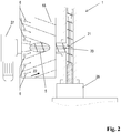
- Fig. 2 a detail of the device in the crushing device in a schematic view from above.
- Fig. 1 the device 1 for comminution of thermoplastic material 2 is shown, comprising a container 3 for receiving the, in particular loosely packed, Kunststoffguts 2 and a projecting into the container 3 or arranged therein shredding device 4 for crushing the plastic material and its promotion to a discharge 5, characterized by air inlets 6 in the crushing device 4 and air outlets 7 in the container wall eighth
- FIG. 1 the device 1 is shown in a sectional view from the side, wherein the selected cutting plane lies vertically in the center of the device 1. This allows a view into the interior of the device 1.
- the moist plastic material 2 passes from the outside by means of a conveyor belt or other, for example, pneumatic conveyor, which in Fig. 1 is not shown and also does not belong to the device 1 according to the invention, through an opening 9 in the container 3 of the device 1.
- the opening 9 is located in the region of the container wall eighth
- the moist plastic material 2 in the container 3 would pass directly in the direction of arrow 10 down to the shredding device 4 and come to lie there close to each other. This would include the residual moisture, which still adheres to the plastic material, included, a drying of the plastic material would be insufficient. Furthermore, the plastics material lying on top of each other would possibly block the gap 11 which is located between the rotor body 12 or the knives 13 fastened thereon, the rotor body 12 rotating in the direction of rotation 14, and the uprights 15, the plastic material 2 thus could not engage in reach the shredder 4 and a trouble-free operation would not be guaranteed.
- the invention is characterized by air inlets 6 in the crushing device 4, in Fig. 1 shown as air inlets 6 in the jacket wall 18, wherein the air from a compressed air generating device 16 is guided via lines to the air inlets 6 and then selectively into the gap 17 between the shell wall 18, which is arranged at a distance from the orbit of the blade 13 of the rotor body 12 is, and the rotor body 12 is injected.
- the air which passes through the air inlets 6 preferably dry in the comminution device 4, guided in the gap 17 mainly in the direction of rotation 14 of the rotor body 12 and thus in the conveying direction of the plastic material 2 and thus 17 moisture is removed from the Kunststoffgut 2 by convection in the gap 17 space Condensate formation on the casing wall 18 and on the rotor body 12 is avoided.
- the compressed air generating device 16 is preferably designed as a side channel compressor 24.
- the main amount of the injected air flows in the direction of rotation 14 along the rotor body 12 through the gap 17 until it at the opposite exit slit 19, which again of one or more stationary knives 15 and on the rotor body 12th attached rotating knives 13 is formed, enters the interior of the container 3.
- a smaller partial flow of the injected air passes contrary to the direction of rotation 14 of the rotor body 12 and thus against the conveying direction of the plastic material 2 within the crushing device 4 through the gap 11 into the interior of the container 3 and thereby possibly loosens in the region of the gap 11 lying Kunststoffgut 2.
- a further smaller partial flow of air blown through the air inlets 6 leaves the gap 17 via the discharge opening 5 and thus passes together with the shredded plastic material in the metering screw 20 and then further into the extruder screw 21, the plastic material for subsequent, in Fig. 1 promotes extruder not shown.
- the air rises from the comminution device 4 in the direction of arrow 22 upwards.
- the flow rate of the air inside the container 3 is selected so that the discontinued plastic material 2 at a low speed in countercurrent in the direction of arrow 10 drops down to the shredder 4 and is dried by the ascending air flow. Very light or flat plastic particles should not be discharged from the container 3.
- a corresponding cover is provided in the region of the opening 9 for the plastic supply, which is designed for example as a fine sieve or flow and adapted to the conveyor, not shown, and the exit of very small plastic particles from the device 1 or through gaps between the device 1 and the conveyor for supplying the plastic material prevented.
- a cover is in Fig. 1 not shown.
- the moist air or steam is discharged in the upper part of the container 3 through air outlets 7 in the container wall 8 out of the device 1 to the environment.
- air outlets 7 are connected to a steam suction device 23.
- the steam extraction device is preferably designed as a radial fan 25, wherein in Fig. 1 two air inlets 7, each with its own radial fan 25 are shown.
- Fig. 1 horizontally in the lower region of the container 3 a stuffing slide 26 is provided. With the help of Stopfschiebers 26, which is moved in the horizontal direction forward and back again, plastic material 2 is reliably supplied to the gap 11. Also shows Fig. 1 the drive 27 of the metering screw 20th
- Fig. 2 shows a detail of the device 1 in the field of crushing device 4 in a schematic sectional view from above.
- the jacket wall 18, which is not here Shown rotor body 12 wrapped, shown with a plurality of air inlets 6.
- the jacket wall 18 is how Fig. 2 shows, profiled by grooves or webs such that the plastic material 2 is pushed together in the gap 17 by the obliquely running grooves or webs in the direction of the centrally disposed discharge opening 5 and from there into the metering screw 20 passes.
- the two screw conveyors 20 and 21 are shown horizontally cut for clarity.
Description
Die Erfindung betrifft eine Vorrichtung zur Zerkleinerung von thermoplastischem Kunststoffgut, die einen Behälter zur Aufnahme des, insbesondere lose gepackten, Kunststoffguts und eine in den Behälter ragende oder darin angeordnete Zerkleinerungseinrichtung zur Zerkleinerung des Kunststoffguts und seiner Förderung zu einer Austragsöffnung umfasst, mit den Merkmalen des Oberbegriffs von Anspruch 1.The invention relates to a device for comminution of thermoplastic material comprising a container for receiving the, in particular loosely packed, plastic material and a crushing device projecting into the container or for comminuting the Kunststoffguts and its promotion to a discharge, with the features of the preamble of
Kunststoffabfälle unterscheiden sich nach ihrer Entstehung und Reinheit. Es wird zwischen Produktions- und sogenannten "Post-Consumer"-Abfällen sowie zwischen sauberen, sortenreinen und vermischten, verschmutzten Kunststoffabfällen unterschieden.Plastic waste varies according to its origin and purity. A distinction is made between production and so-called "post-consumer" waste and between clean, single-grade and mixed, polluted plastic waste.
Bei der industriellen Herstellung von Kunststoffprodukten fällt ein Ausschuss an, welcher während des Anfahrens, Umstellens oder der Wartung von Anlagen entsteht, bis die geforderten Produktdaten erreicht sind, oder der durch das Produktionsverfahren selbst bedingt ist, beispielsweise als Stanzabfall oder als zu verwerfender Randstreifen von Blasfolien.In the industrial production of plastic products, a scrap arises, which arises during the start-up, conversion or maintenance of equipment until the required product data is reached, or which is caused by the production process itself, for example as punching waste or as a discardable edge strip of blown film ,
Bevor Kunststoffabfälle dem eigentlichen Recycling zugeführt werden können, müssen diese rein vorliegen. Dazu werden sie beispielsweise in die einzelnen Fraktionen Polyolefine (als Vertreter seien hier Polyethylen PE sowie Polypropylen PP genannt), Polyvinylchlorid (PVC) und Polystyrol getrennt und es werden anhaftende Fremdstoffe, wie beispielsweise Metalle oder Farben meist mit physikalischen Verfahren entfernt. Die sortenreinen Kunststoffabfälle werden üblicherweise danach mit Wasser gereinigt und anschließend mit gängigen Verfahren der Kunststoffverarbeitung aufbereitet. Zu diesen Verfahren gehören z.B. Extrusion, Spritzgieß- bzw. Spritzpressverfahren, Intrusion und Sinterpressverfahren.Before plastic waste can be sent to the actual recycling, it must be pure. For this they are, for example, in the individual fractions polyolefins (as representatives here are called polyethylene PE and polypropylene PP), polyvinyl chloride (PVC) and polystyrene separated and there are adhering foreign substances, such as metals or paints usually removed by physical processes. The sorted plastic waste is usually then cleaned with water and then processed by standard methods of plastics processing. These methods include e.g. Extrusion, injection molding or transfer molding, intrusion and sintering processes.
Problematisch bei der Verarbeitung von gesammelten Kunststoffabfällen sind dabei die stark schwankenden Betriebsbedingungen bei der Beschickung derartiger Recyclinganlagen. So müssen unterschiedliche Gehalte an Restfeuchte, Verschmutzungen, Dichteschwankungen und Aufgabeportionen beherrscht werden, um aus einem heterogenen Abfall ein homogenes Produkt mit gleichbleibender Produktqualität zu erzielen.The problem with the processing of collected plastic waste are the highly fluctuating operating conditions when loading such recycling plants. Thus, different contents of residual moisture, contamination, density fluctuations and task portions must be mastered in order to achieve a homogeneous product with consistent product quality from a heterogeneous waste.
Nasse Kunststoffabfälle werden zumeist in Zentrifugen getrocknet, durch die Zentrifugalkraft wird die Abtrennung der auf dem Kunststoff anhaftenden Flüssigkeit dabei wesentlich beschleunigt. Nachteilig dabei ist neben dem hohen Energieaufwand die durch die Zentrifugalkraft scheinbare Gewichtszunahme des zu trocknenden Gutes sowie die hohe Verdichtung des Abfallstoffes, der anschließend mit erheblichem Kraftaufwand wieder gelockert und weiter transportiert werden muss.Wet plastic waste is usually dried in centrifuges, the centrifugal force, the separation of adhering to the plastic liquid is significantly accelerated. The disadvantage here is in addition to the high energy consumption apparent by the centrifugal force weight gain of the material to be dried and the high compression of the waste, which then loosened again with considerable effort and must be transported on.
Aus dem Stand der Technik ist dazu beispielsweise aus der
Nachteilig an dieser Ausführung ist, dass das gesamte zu trocknende Gut in der Zentrifuge mit hohem Energieeintrag beschleunigt werden muss und dabei zwangsläufig verdichtet wird. Zur Lockerung des Kunststoffabfalls, um eine Weiterförderung zu ermöglichen, gelangt das Gut am unteren Ende schließlich zu einem Radialgebläse, welches das getrocknete Gut erfasst und es durch Ausblassstutzen aus der Vorrichtung austreibt. Das Radialgebläse wird dabei allerdings sehr stark beansprucht, es muss deshalb und auch zur Reduzierung des entstehenden Lärms besonders dickwandig ausgeführt werden. Damit müssen im Gebläse dieser Vorrichtung zusätzliche schwere Massen mit hohem Energieaufwand laufend angetrieben werden. Eine Zerkleinerung des Kunststoffabfalls findet nicht oder nur geringfügig statt.A disadvantage of this design is that the entire material to be dried in the centrifuge with high energy input must be accelerated and is inevitably compressed. To loosen the plastic waste in order to allow further promotion, the good finally arrives at the lower end to a radial fan, which detects the dried material and expels it through Ausblassstutzen from the device. The radial blower is, however, very heavily stressed, it must therefore be carried out particularly thick-walled and also to reduce the resulting noise. Thus, in the blower of this device additional heavy masses must be driven continuously with high energy consumption. A shredding of the plastic waste does not take place or only slightly.
Die
Nachteilig an dieser Vorrichtung ist, dass sie nicht kontinuierlich betrieben werden kann, da hier - vergleichbar mit einer elektrischen Kaffeemühle - nach dem Befüllen mit einer Charge des zu zerkleinernden Gutes ein Deckel geschlossen werden muss, bevor das Schneidwerkzeug in Gang gesetzt werden kann. Dabei kommt es sowohl bei der einfachen Ausführung, als auch bei der Ausführung mit einer rotierenden Siebtrommel zur Verdichtung der zerkleinerten Kunststoffschnitzel, da diese erst nach mehreren Befüllzyklen gesammelt dem Fangkorb entnommen werden. Außerdem ist eine derartige Betriebsführung zeitintensiv und bedingt einen erhöhten Überwachungs- und Wartungsaufwand.A disadvantage of this device is that it can not be operated continuously, since here - comparable to an electric coffee grinder - after filling with a batch of material to be shredded a lid must be closed before the cutting tool can be set in motion. It comes in both the simple design, as well as in the version with a rotating screen drum for compacting the shredded plastic shreds, since they are collected collected after several filling cycles the catcher. In addition, such operation is time-consuming and requires increased monitoring and maintenance.
Eine kontinuierliche Weiterverarbeitung eines derart vorbehandelten Abfalls erfordert daher zumindest einen weiteren Vorratsbehälter als Zwischenspeicher der einzelnen Abfallchargen sowie eine geeignete Vorrichtung, damit die verdichteten Kunststoffschnitzel wieder gelockert werden und zu den nachfolgenden Arbeitsschritten befördert werden können.A continuous further processing of such pretreated waste therefore requires at least one further storage container as a buffer of the individual waste batches and a suitable device so that the compacted plastic shreds are loosened again and can be transported to the subsequent operations.
Die
Nachteilig an dieser Vorrichtung ist, dass es während des Betriebs im Bereich des Aufnahmebehälters, der oberhalb der rotierenden Scheibe mit den Mischwerkzeugen liegt, zu einer Thrombenbildung und damit zu einer Verdichtung des feuchten Kunststoffmaterials an den Außenwänden des Aufnahmebehälters kommt. Das eingedüste, aufsteigende Gas kann in diesem Bereich das feuchte Kunststoffmaterial nur unzureichend durchströmen, die erwünschte Trocknung wird dadurch behindert. Weiters ist es mit dieser Vorrichtung nicht möglich, eine gleichmäßige, enge Korngrößenverteilung der Kunststoffpartikel zu gewährleisten, denn es können auch größere, flächige Kunststoffabfälle im Ringspalt an den Mischwerkzeugen vorbei direkt zur Austragsöffnung gelangen, ohne zerkleinert worden zu sein. Eine Verblockung der Austragsöffnung durch größere flächige Kunststoffteile und dadurch bedingte Betriebsstörungen sind dann die Folge. Weiters können größere Kunststoffteile und schwer zerkleinerbare Materialien mit dieser Vorrichtung nicht ohne eine Vorzerkleinerung verarbeitet werden.A disadvantage of this device is that it comes during operation in the region of the receptacle, which is above the rotating disc with the mixing tools, to a thrombus formation and thus to a densification of the wet plastic material on the outer walls of the receptacle. The injected, rising gas can only insufficiently flow through the moist plastic material in this area, the desired drying is hindered. Furthermore, it is not possible with this device to ensure a uniform, narrow particle size distribution of the plastic particles, because it can get even larger, flat plastic waste in the annular gap past the mixing tools directly to the discharge, without having been crushed. A blockage of the discharge through larger flat plastic parts and consequent malfunctions are then the result. Furthermore, larger plastic parts and difficult to size materials can not be processed without pre-shredding with this device.
Es besteht demnach Bedarf zur Verbesserung der Nachteile des Standes der Technik derartiger Vorrichtungen, die Kunststoffabfall zerkleinern und auch trocknen können. Es soll eine Vorrichtung zur Verfügung gestellt werden, die vorzugsweise im kontinuierlichen Betrieb ohne energieaufwändige Zentrifugen eine effiziente Trocknung feuchter Kunststoffabfälle sowie gleichzeitig auch deren zuverlässige Zerkleinerung gewährleistet und das so vorbehandelte Abfallmaterial anschließend direkt in einen Extruder gefördert werden kann.There is therefore a need to improve the disadvantages of the prior art of such devices, which can shred plastic waste and also dry. It should be made available a device that ensures preferably in continuous operation without energy-consuming centrifuges efficient drying wet plastic waste and at the same time their reliable comminution and the pretreated waste material can then be conveyed directly into an extruder.
Diese Aufgaben werden von einer Vorrichtung zur Zerkleinerung von thermoplastischem Kunststoffgut gemäß dem Oberbegriff von Anspruch 1 mit den Merkmalen des kennzeichnenden Teiles von Anspruch 1 gelöst.These objects are achieved by a device for comminution of thermoplastic material according to the preamble of
Vorteilhafte Ausgestaltungen der Erfindung sind in den abhängigen Ansprüchen und der Beschreibung dargestellt.Advantageous embodiments of the invention are set forth in the dependent claims and the description.
Bei einer erfindungsgemäßen Vorrichtung zur Zerkleinerung von thermoplastischem Kunststoffgut, umfassend einen Behälter zur Aufnahme des, insbesondere lose gepackten, Kunststoffguts und eine in den Behälter ragende oder darin angeordnete Zerkleinerungseinrichtung zur Zerkleinerung des Kunststoffguts, und seiner Förderung zu einer Austragsöffnung, wobei die Zerkleinerungseinrichtung zumindest einen um eine waagrechte Rotationsachse drehbaren Rotorkörper umfasst, der an seiner Umfangsfläche mit Messern bestückt ist, wobei vorzugsweise im Behälter nahe der Umlaufbahn der Messer des Rotorkörpers stehende Messer angeordnet sind, die mit den Messern des Rotorkörpers einen Schereffekt auf das Kunststoffgut ausüben, wobei die Vorrichtung Lufteinlässe im Bereich der Zerkleinerungseinrichtung und Luftauslässe in der Behälterwand aufweist, und wobei die Vorrichtung eine den Rotorkörper zumindest teilweise umgebende Mantelwand aufweist, die in einem Abstand von der Umlaufbahn der Messer des Rotorkörpers angeordnet ist und durch Rillen oder Stege profiliert ist, wobei die Lufteinlässe in der Mantelwand angeordnet sind, wobei die Luft aus einer Drucklufterzeugungseinrichtung über Leitungen zu den Lufteinlässen geführt wird, und wobei eine Führung der Luft im Spaltraum hauptsächlich in Umdrehungsrichtung des Rotorkörpers und damit in Förderrichtung des Kunststoffgutes erfolgt, wobei die Zerkleinerungseinrichtung zur Förderung des Kunststoffguts zu einer Austragsöffnung ausgebildet ist, wobei die Rillen oder Stege bei Drehung des Rotorkörpers das Kunststoffgut im Spaltraum in Richtung der Austragsöffnung zusammenschieben.In a device according to the invention for the comminution of thermoplastic material, comprising a container for receiving the, in particular loosely packed, plastic material and arranged in the container or arranged therein shredding device for crushing the plastic material, and its promotion to a discharge, wherein the shredding device at least one order a horizontal axis of rotation rotatable rotor body comprises, which is equipped on its peripheral surface with knives, preferably in the container near the orbit of the knife rotor body standing knife are arranged, which exert a shear effect on the plastic goods with the blades of the rotor body, wherein the device air intakes in Having the area of the crushing device and air outlets in the container wall, and wherein the device comprises a rotor body at least partially surrounding the shell wall, which at a distance from the orbit of the Knife of the rotor body is arranged and profiled by grooves or webs, wherein the air inlets are arranged in the shell wall, wherein the air is guided from a compressed air generating device via lines to the air inlets, and wherein a guide of the air in the gap space mainly in the direction of rotation of the rotor body and thus takes place in the conveying direction of the plastic material, wherein the shredding device is designed to convey the plastic material to a discharge, wherein the grooves or webs push the plastics material in the gap in the direction of the discharge opening upon rotation of the rotor body.
Die vorliegende Erfindung bietet die folgenden Vorteile gegenüber dem bekannten Stand der Technik:
- Die Vorrichtung kann vollkontinuierlich und wartungsarm betrieben werden und damit zur Trocknung sowie Zerkleinerung von thermoplastischem Kunststoffgut direkt vor einem kontinuierlich arbeitenden Kunststoff-Extruder eingesetzt werden.
- Sowohl die Oberflächenfeuchte, als auch die vom Material hygroskopisch aufgenommene Feuchte können in der erfindungsgemäßen Vorrichtung getrocknet werden.
- Eine ausschließlich chargenweise Befüllung mit Kunststoffgut ist bei dieser Vorrichtung nicht erforderlich.
- Eine Manipulation und chargenweise Entleerung von getrocknetem und zerkleinertem Kunststoffgut entfällt, das behandelte Kunststoffgut wird kontinuierlich mittels Dosierschnecke aus der Vorrichtung herausgefördert.
- Eine Verdichtung des Kunststoffgutes, zu der es beispielsweise während des Abschleuderns in einer Zentrifuge zwangsläufig kommt, entfällt. Hier bleibt das feuchte Kunststoffgut im Aufnahmebehälter lose verteilt.
- Bei der erfindungsgemäßen Vorrichtung wird im Bereich des Aufnahmebehälters kein rotierender Zentrifugeneinsatz, beispielsweise ein Siebkorb, samt zugehörigem Antrieb benötigt. Eine besonders robuste Ausführung des Gehäuses mit größeren Wandstärken im Bereich des Aufnahmebehälters sowie zusätzliche Sicherheitseinrichtungen, wie bei Zentrifugen erforderlich, die das Herausschleudern des Gutes verhindern bzw. das Bedienungspersonal vor Verletzungen schützen sollen, müssen hier nicht vorgesehen werden. Die Vorrichtung kann damit wesentlich kostengünstiger gebaut werden.
- Durch die Wahl der Lufteinlässe im Bereich der Zerkleinerungseinrichtung wird das Kunststoffgut sowohl in der Zerkleinerungseinrichtung, als auch im Aufnahmebehälter getrocknet. Damit wird eine Kondensatbildung im Inneren der gesamten Vorrichtung zuverlässig verhindert.
- Durch die Konvektionsströmung im Inneren des Aufnahmebehälters, hervorgerufen durch das Einleiten von vorzugsweise trockener, vorgewärmter Luft in die Zerkleinerungseinrichtung und dann weiter in den Aufnahmebehälter bzw. durch die Absaugung der feuchten Luft aus dem Aufnahmebehälter wird für das darin lose verteilte Kunststoffgut eine schnelle Trocknungskinetik erzielt.
- Sollte das aufzubereitende Kunststoffgut vor seiner Zufuhr zur Vorrichtung bereits verdichtet gewesen sein, so wird es im Aufnahmebehälter aufgrund der dort herrschenden Konvektionsströmung gelockert.
- Durch Einblasen der Luft direkt im Bereich der Zerkleinerungseinrichtung und durch Lenken der Luft im Spaltraum hauptsächlich in der gleichen Strömungsrichtung (im Gleichstrom) wie das zu fördernde Kunststoffgut wird zusätzlich die Zufuhr des Kunststoffgutes zur Zerkleinerungseinrichtung unterstützt. Das gesamte Kunststoffgut wird damit zuverlässig in die Zerkleinerungseinrichtung geführt, bevor es von dort zur Austragsöffnung der Vorrichtung gelangen kann.
- Die Vorrichtung ist derart konzipiert, dass nur Kunststoffgut, das mindestens einmal von der Zerkleinerungseinrichtung erfasst wurde und dabei weiter zerkleinert wurde, zur Austragsöffnung der Vorrichtung und danach beispielsweise in einen Kunststoff-Extruder gelangt. Dadurch werden Folgeschäden wie Verblockungen an nachfolgenden Recycling-Maschinen vermieden.
- Auch große Kunststoffteile und schwer zerkleinerbare Materialien können einstufig verarbeitet werden.
- The device can be operated fully continuous and low maintenance and thus used for drying and comminution of thermoplastic material directly in front of a continuously operating plastic extruder.
- Both the surface moisture and the moisture absorbed hygroscopically by the material can be dried in the device according to the invention.
- An exclusively batch filling with plastic material is not required in this device.
- A manipulation and batch emptying of dried and crushed plastic material deleted, the treated plastic material is continuously conveyed out by means of metering screw from the device.
- A compaction of the plastic material, which inevitably occurs during spin-off in a centrifuge, is eliminated. Here it stays moist plastic material loosely distributed in the receptacle.
- In the apparatus according to the invention, no rotating centrifuge insert, for example a screen basket, together with the associated drive is required in the region of the receptacle. A particularly robust design of the housing with larger Wall thicknesses in the area of the receptacle and additional safety devices, such as centrifuges required to prevent the ejection of the goods or to protect the operator from injury need not be provided here. The device can thus be built much cheaper.
- By choosing the air inlets in the crushing device, the plastic material is dried both in the crushing device, as well as in the receptacle. This reliably prevents condensation inside the entire device.
- Due to the convection flow in the interior of the receptacle, caused by the introduction of preferably dry, preheated air into the shredder and then further into the receptacle or by the suction of the moist air from the receptacle is achieved for the loose loose plastic material therein a rapid drying kinetics.
- If the plastic material to be processed has already been compressed before being fed to the device, it is loosened in the receiving container due to the convection flow prevailing there.
- By blowing in the air directly in the crushing device and by directing the air in the gap mainly in the same flow direction (in cocurrent) as the plastic material to be conveyed, the supply of the plastic material to the shredding device is additionally supported. The entire plastic material is thus reliably guided into the comminution device before it can get from there to the discharge opening of the device.
- The device is designed such that only plastic material that has been detected at least once by the comminution device and thereby further comminuted, reaches the discharge opening of the device and then, for example, into a plastic extruder. As a result, consequential damage such as blockages on subsequent recycling machines are avoided.
- Even large plastic parts and difficult-to-size materials can be processed in one step.
Mit aus den Dokumenten
In einer bevorzugten Ausführungsform der Erfindung umfasst die Vorrichtung eine Drucklufterzeugungseinrichtung, deren Ausgang an die Lufteinlässe der Vorrichtung angeschlossen ist. Die Aufgabe der Drucklufterzeugungseinrichtung besteht darin, Druckluft in ausreichender Menge zur Verfügung zu stellen, um eine Konvektionsströmung im Inneren der Vorrichtung zu erzeugen und damit den gewünschten Trocknungseffekt für das feuchte Kunststoffgut zu erreichen.In a preferred embodiment of the invention, the device comprises a compressed air generating device whose output to the air inlets of the device connected. The task of the compressed air generating device is to provide compressed air in sufficient quantity to produce a convection flow in the interior of the device and thus to achieve the desired drying effect for the moist plastic material.
Weiters kann die erfindungsgemäße Vorrichtung eine Dampfabsaugeinrichtung aufweisen, die an die Luftauslässe der Vorrichtung angeschlossen ist. Die feuchte Luft bzw. der Dampf wird damit zuverlässig aus der Vorrichtung abgeführt und an die Umgebung geleitet. Damit werden eine Kondensatbildung in der Vorrichtung sowie ein unerwünschtes weiteres Befeuchten des feuchten Kunststoffgutes durch den sonst vorhandenen Dampf im Inneren des Behälters verhindert.Furthermore, the device according to the invention may have a vapor suction device which is connected to the air outlets of the device. The moist air or steam is thus reliably removed from the device and directed to the environment. This condensate formation in the device and an undesirable further moistening of the moist plastic material are prevented by the otherwise existing vapor inside the container.
Vorteilhafterweise ist bei der Vorrichtung die Drucklufterzeugungseinrichtung als Seitenkanalverdichter ausgebildet. Derartige Seitenkanalverdichter sind für alle Anwendungen geeignet, bei denen mehr Druck benötigt wird als herkömmliche Ventilatoren erzeugen können. Die rotierenden Teile eines Seitenkanalverdichters berühren das Gehäuse nicht, es gibt also keine Reibung und deshalb ist auch keine Schmierung notwendig. Der Verdichtungsvorgang erfolgt absolut ölfrei und kohlenstaubfrei, eine Verunreinigung der Luft findet nicht statt.Advantageously, in the device, the compressed air generating device is designed as a side channel compressor. Such side channel blowers are suitable for all applications where more pressure is needed than conventional fans can produce. The rotating parts of a side channel compressor do not touch the housing, so there is no friction and therefore no lubrication is necessary. The compression process is absolutely oil-free and free of carbon dust, contamination of the air does not take place.
Vorzugsweise ist die Dampfabsaugeinrichtung als Radialgebläse ausgeführt.Preferably, the Dampfabsaugeinrichtung is designed as a radial fan.
Die Vorrichtung ist zweckmäßigerweise so gestaltet, dass der Behälter zur Aufnahme des Kunststoffgutes mit der Umgebung kommuniziert. Durch diese oben offene Bauweise des Behälters ist es einfach möglich, beispielsweise mit einem Förderband oder Förderschacht das feuchte Kunststoffgut in die Vorrichtung zu füllen. Der Aufnahmebehälter kann mit einer Abdeckhaube oder dergleichen ausgerüstet sein, um ein Austragen sehr leichter Kunststoffpartikel aus der Vorrichtung zu verhindern. Eine derartige Abdeckhaube ist aber zumindest mit einer Öffnung für die Zufuhr des Kunststoffgutes versehen.The device is expediently designed so that the container for receiving the plastic material communicates with the environment. By this open-top construction of the container, it is easily possible to fill the moist plastic material into the device, for example with a conveyor belt or conveyor shaft. The receptacle may be equipped with a cover or the like to prevent discharge of very light plastic particles from the device. However, such a cover is provided at least with an opening for the supply of plastic material.
Die Einrichtung zur Zerkleinerung des Kunststoffgutes, welche in den Aufnahmebehälter der Vorrichtung ragt oder darin angeordnet ist, umfasst einen um eine Rotationsachse drehbaren Rotorkörper, der an seiner Umfangfläche mit Messern bestückt ist, wobei vorzugsweise im Behälter nahe der Umlaufbahn der Messer des Rotorkörpers stehende Messer angeordnet sind, die mit den Messern des Rotorkörpers einen Schereffekt auf das Kunststoffgut ausüben. Zusätzlich kann im Bereich der Materialaufgabe in die Zerkleinerungseinrichtung noch ein Stopfschieber vorhanden sein, der regelmäßig vor und zurück bewegt wird und somit sichergestellt wird, dass das Kunststoffgut vom mit Messern bestückten Rotorkörper erfasst, anschließend in den Spalt zwischen Rotorkörper und stehenden Messern gelangt und dort durch Scherwirkung weiter zerkleinert wird.The device for comminuting the plastic material, which protrudes into the receptacle of the device or is arranged therein comprises a rotatable about a rotation axis rotor body which is equipped on its peripheral surface with knives, preferably arranged in the container near the orbit of the blade of the rotor body standing knife are that exert a shearing effect on the plastic goods with the knives of the rotor body. In addition, in the area of the material feed into the comminuting device there may still be a stuffing gate, which is moved back and forth regularly, and thus it is ensured that the plastic material is picked up by the rotor body equipped with knives, then passed into the gap between the rotor body and stationary knives, where it is further comminuted by shearing action.
In der Vorrichtung wird der Rotor der Zerkleinerungseinrichtung zumindest teilweise von einer Mantelwand umgeben, die in einem Abstand von der Umlaufbahn der Messer des Rotorkörpers angeordnet ist, wobei die Lufteinlässe in der Mantelwand angeordnet sind. Mit dieser Ausführungsform wird der Spaltraum um den Rotorkörper, beginnend mit dem ersten stehenden Messer und anschließend in Umfangsrichtung des Rotorkörpers durch die Mantelwand begrenzt, weiter fortgesetzt und es wird eine längere Einwirkung der Scherkräfte auf das Kunststoffgut und damit eine noch effizientere Zerkleinerung erreicht. Die Lufteinlässe in der Mantelwand versorgen die Zerkleinerungseinrichtung mit trockener Luft, welche die noch vorhandene Restfeuchte auf dem Kunststoffgut innerhalb der Zerkleinerungseinrichtung aufnimmt und danach als feuchte Luft bzw. Dampf im Aufnahmebehälter aufsteigt.In the apparatus, the rotor of the comminution device is at least partially surrounded by a casing wall, which is arranged at a distance from the orbit of the blades of the rotor body, wherein the air inlets are arranged in the casing wall. With this embodiment, the gap space around the rotor body, starting with the first stationary knife and then delimited in the circumferential direction of the rotor body by the jacket wall, continues and a longer effect of the shear forces on the plastic material and thus an even more efficient comminution is achieved. The air inlets in the shell wall supply the shredder with dry air, which absorbs the residual moisture remaining on the plastic material within the shredder and then rises as moist air or vapor in the receptacle.
Durch Vorsehen einer Fördereinrichtung, insbesondere einer Dosierschnecke, die an die Austragsöffnung der Vorrichtung angeschlossen ist, wird vorteilhaft das zerkleinerte und getrocknete Kunststoffgut kontinuierlich aus der Vorrichtung ausgetragen. Damit kann die Vorrichtung ohne Pufferbehälter direkt mit einer nachfolgenden Verfahrenseinheit, wie beispielsweise einem kontinuierlich arbeitenden Kunststoff-Extruder verbunden werden.By providing a conveying device, in particular a metering screw, which is connected to the discharge opening of the device, advantageously the comminuted and dried plastic material is continuously discharged from the device. Thus, the device without buffer container can be connected directly to a subsequent processing unit, such as a continuous plastic extruder.
Die Erfindung wird nun anhand eines Ausführungsbeispiels, auf das die Erfindung jedoch nicht beschränkt ist, unter Bezugnahme auf die folgenden Zeichnungen näher beschrieben. In den Zeichnungen zeigen:
In
Zur besseren Übersicht ist in
Das feuchte Kunststoffgut 2 gelangt von außen mittels Förderband oder einer anderwärtigen, beispielsweise pneumatischen Fördereinrichtung, die in
Aufgrund der Schwerkraft würde das feuchte Kunststoffgut 2 im Behälter 3 direkt in Pfeilrichtung 10 nach unten zur Zerkleinerungseinrichtung 4 gelangen und dort dicht aufeinander zu liegen kommen. Damit wäre auch die Restfeuchte, die auf dem Kunststoffgut noch anhaftet, eingeschlossen, eine Trocknung des Kunststoffgutes wäre nur unzureichend möglich. Weiters würde das aufeinander liegende Kunststoffgut den Spalt 11, der sich zwischen dem Rotorkörper 12 bzw. den darauf befestigten Messern 13, wobei der Rotorkörper 12 in Umdrehungsrichtung 14 rotiert, und den stehenden Messern 15 befindet, möglicherweise verblocken, das Kunststoffgut 2 könnte somit nicht in den Zerkleinerer 4 gelangen und ein störungsfreier Betrieb wäre damit nicht gewährleistet.Due to gravity, the moist
Daher ist die Erfindung durch Lufteinlässe 6 im Bereich der Zerkleinerungseinrichtung 4 gekennzeichnet, in
Die Drucklufterzeugungseinrichtung 16 ist vorzugsweise als Seitenkanalverdichter 24 ausgeführt.The compressed
Die Hauptmenge der eingeblasenen Luft strömt in Drehrichtung 14 entlang des Rotorkörpers 12 durch den Spaltraum 17, bis sie am gegenüberliegenden Austrittsspalt 19, der abermals von einem oder mehreren stehenden Messern 15 und den auf dem Rotorkörper 12 befestigten drehenden Messern 13 gebildet wird, in den Innenraum des Behälters 3 gelangt. Ein kleinerer Teilstrom der eingeblasenen Luft gelangt entgegen der Drehrichtung 14 des Rotorkörpers 12 und damit entgegen der Förderrichtung des Kunststoffgutes 2 innerhalb der Zerkleinerungseinrichtung 4 durch den Spalt 11 in das Innere des Behälters 3 und lockert dabei allfällig im Bereich des Spalts 11 liegendes Kunststoffgut 2. Ein weiterer kleinerer Teilstrom der über die Lufteinlässe 6 eingeblasenen Luft verlässt den Spaltraum 17 über die Austragsöffnung 5 und gelangt damit gemeinsam mit dem zerkleinerten Kunststoffgut in die Dosierschnecke 20 und dann weiter in die Extruderschnecke 21, die das Kunststoffgut zum nachfolgenden, in
Im Inneren des Behälters 3 steigt die Luft von der Zerkleinerungseinrichtung 4 in Pfeilrichtung 22 nach oben. Die Strömungsgeschwindigkeit der Luft im Inneren des Behälters 3 wird so gewählt, dass das aufgegebene Kunststoffgut 2 mit geringer Geschwindigkeit im Gegenstrom in Pfeilrichtung 10 nach unten zur Zerkleinerungseinrichtung 4 sinkt und dabei vom aufsteigenden Luftstrom getrocknet wird. Sehr leichte oder flächige Kunststoffpartikel sollen dabei nicht aus dem Behälter 3 ausgetragen werden.Inside the
Zweckmäßigerweise ist dazu eine entsprechende Abdeckhaube im Bereich der Öffnung 9 für die Kunststoffzufuhr vorgesehen, die beispielsweise als feines Sieb oder Fließ ausgeführt und an die nicht dargestellte Fördereinrichtung angepasst ist, und den Austritt sehr kleiner Kunststoffpartikel aus der Vorrichtung 1 bzw. durch Spalte zwischen der Vorrichtung 1 und der Fördereinrichtung zur Zufuhr des Kunststoffgutes verhindert. Eine derartige Abdeckhaube ist in
Die feuchte Luft bzw. der Dampf wird im oberen Teil des Behälters 3 über Luftauslässe 7 in der Behälterwand 8 aus der Vorrichtung 1 heraus an die Umgebung abgeführt. In
Weiters ist in
Claims (6)
- A device (1) for size reduction of thermoplastic goods (2), comprising a container (3) for receiving the in particular loosely packed thermoplastic goods and a size reduction device (4) projecting into the container or arranged therein for reducing the thermoplastic goods in size, wherein the size reduction device (4) comprises at least one rotor body (12) rotatable around a horizontal axis of rotation, which is equipped at its circumferential surface with knives (13), wherein there are arranged preferably in the container (3) near the trajectory of the knives (13) of the rotor body (12) standing knives (15), which exert a shear effect with the knives of the rotor body onto the thermoplastic goods, wherein the device has air inlets (6) in the region of the size reduction device (4) and air outlets (7) in the container wall (8), and wherein the device (1) has a sheath wall (18) surrounding at least in part the rotor body (12), which is arranged spaced apart from the trajectory of the knives (13) of the rotor body (12) and is shaped by grooves or ridges, wherein the air inlets (6) are arranged in the sheath wall (18), wherein the air inlets (6) are arranged in the sheath wall (18), wherein the air is guided from a device for the generation of compressed air (16) via pipes to the air inlets (6), and wherein air is guided in the space of the gap (17) mainly in the direction of rotation (14) of the rotor body (12) and, hence, in the conveying direction of the thermoplastic goods (2), characterized in that the size reduction device (4) is configured to convey the thermoplastic goods to a discharge opening (5), wherein the grooves or ridges, upon rotation of the rotor body (12), push together the thermoplastic goods (2) within the gap space (17) in the direction to the discharge opening (5).
- A device (1) according to claim 1, characterized by a device for the generation of compressed air (16), the discharge of which being attached to the air inlets (6).
- A device (1) according to claim 1 or 2, characterized by a steam suction device (23) attached to the air outlets (7).
- A device (1) according to claim 2 or 3, characterized by the fact that the device for the generation of compressed air (16) is formed as a lateral channel compressor (24) and/or the steam suction device (23) as a radial blower (25).
- A device (1) according to any of the preceding claims, characterized by the fact that the container (3) is in communication with the surrounding.
- A device (1) according to any of the preceding claims, characterized by the fact that there is attached at the discharge opening (5) a conveyor device (20) for the reduced thermoplastic goods, in particular a dosing screw.
Priority Applications (1)
| Application Number | Priority Date | Filing Date | Title |
|---|---|---|---|
| PL10701493T PL2393598T3 (en) | 2009-02-03 | 2010-01-15 | Device for reducing plastic |
Applications Claiming Priority (2)
| Application Number | Priority Date | Filing Date | Title |
|---|---|---|---|
| AT0018509A AT507856B1 (en) | 2009-02-03 | 2009-02-03 | DEVICE FOR CRUSHING PLASTIC |
| PCT/EP2010/050439 WO2010089174A1 (en) | 2009-02-03 | 2010-01-15 | Device for reducing plastic |
Publications (2)
| Publication Number | Publication Date |
|---|---|
| EP2393598A1 EP2393598A1 (en) | 2011-12-14 |
| EP2393598B1 true EP2393598B1 (en) | 2019-05-29 |
Family
ID=42122994
Family Applications (1)
| Application Number | Title | Priority Date | Filing Date |
|---|---|---|---|
| EP10701493.8A Active EP2393598B1 (en) | 2009-02-03 | 2010-01-15 | Device for reducing plastic |
Country Status (8)
| Country | Link |
|---|---|
| US (1) | US20120037739A1 (en) |
| EP (1) | EP2393598B1 (en) |
| JP (1) | JP5650665B2 (en) |
| AT (1) | AT507856B1 (en) |
| BR (1) | BRPI1008809B1 (en) |
| ES (1) | ES2743299T3 (en) |
| PL (1) | PL2393598T3 (en) |
| WO (1) | WO2010089174A1 (en) |
Families Citing this family (5)
| Publication number | Priority date | Publication date | Assignee | Title |
|---|---|---|---|---|
| US10725451B2 (en) * | 2013-10-21 | 2020-07-28 | Made In Space, Inc. | Terrestrial and space-based manufacturing systems |
| AT517755A1 (en) * | 2015-09-22 | 2017-04-15 | Next Generation Recyclingmaschinen Gmbh | Apparatus and method for processing thermoplastic with an improved shredding / transporting device |
| AT517756B1 (en) * | 2015-09-22 | 2017-11-15 | Next Generation Recyclingmaschinen Gmbh | Apparatus and method for processing thermoplastic with a blowing device for a screw conveyor |
| CN107115934B (en) * | 2016-10-26 | 2022-09-20 | 宁波意菲特机械制造有限公司 | Double-end interactive crushing efficient shredder |
| AT523082B1 (en) * | 2019-10-16 | 2022-07-15 | Pureloop Gesmbh | Device for processing material, in particular plastic material |
Family Cites Families (16)
| Publication number | Priority date | Publication date | Assignee | Title |
|---|---|---|---|---|
| US3960334A (en) * | 1975-02-24 | 1976-06-01 | Cumberland Engineering Company, Inc. | Size reduction apparatus |
| DE2609850A1 (en) * | 1976-03-10 | 1977-09-15 | Weiss Gmbh & Co Kg Maschinen F | Disintegrating and sintering thin thermoplastic waste - by using frictional heat from rotating cutters plus hot air current |
| DE3543370A1 (en) * | 1985-12-07 | 1987-06-11 | Jackering Altenburger Masch | MILL WITH SEVERAL GRINDINGS |
| JPS62282654A (en) * | 1986-05-30 | 1987-12-08 | マテックス株式会社 | Force feeder for runner ground product |
| DE9202161U1 (en) | 1992-02-20 | 1992-04-09 | Schmoll, Heinz, 6242 Kronberg, De | |
| US5402948A (en) * | 1993-04-30 | 1995-04-04 | Kaczmarek; Al | Comminuting device with face |
| JPH07150492A (en) * | 1993-11-30 | 1995-06-13 | Mitsubishi Heavy Ind Ltd | Device for compression-molding waste paper and sheet disintegrator and cutter |
| DE4425765C2 (en) * | 1994-07-21 | 1999-01-07 | Duerr Systems Gmbh | System for cleaning workpieces using a compressed air jet |
| US5556039A (en) * | 1994-10-28 | 1996-09-17 | Nissei Plastic Industrial Co., Ltd. | Crushing machine apparatus and a method for cleaning the crushing machine apparatus |
| JPH08257428A (en) * | 1995-03-22 | 1996-10-08 | Fuji Photo Film Co Ltd | Pulverizer for photographic processing composition container |
| JP2001190979A (en) * | 2001-03-15 | 2001-07-17 | Taisei Jushi:Kk | High speed rotating crusher |
| US6749138B2 (en) * | 2002-03-05 | 2004-06-15 | Phoenix Technologies, L.P. | Granulator |
| US7077344B2 (en) * | 2002-03-12 | 2006-07-18 | Starlinger & Co. Gesellschaft M.B.H. | Device for the comminution of materials |
| DE102005003849B3 (en) * | 2005-01-27 | 2006-04-20 | Daimlerchrysler Ag | Ventilated seat for vehicle has ventilation layer integrated into upholstery in order to ventilate it |
| AT503390B1 (en) | 2006-03-30 | 2008-06-15 | Erema | DEVICE FOR DRYING WET BREAKABLE GOOD, PREFERABLY OF PLASTIC PARTICLES |
| AT504854B1 (en) * | 2007-02-15 | 2012-08-15 | Erema | METHOD AND DEVICE FOR PREPARING A MATERIAL |
-
2009
- 2009-02-03 AT AT0018509A patent/AT507856B1/en not_active IP Right Cessation
-
2010
- 2010-01-15 US US13/146,914 patent/US20120037739A1/en not_active Abandoned
- 2010-01-15 WO PCT/EP2010/050439 patent/WO2010089174A1/en active Application Filing
- 2010-01-15 PL PL10701493T patent/PL2393598T3/en unknown
- 2010-01-15 ES ES10701493T patent/ES2743299T3/en active Active
- 2010-01-15 JP JP2011548630A patent/JP5650665B2/en active Active
- 2010-01-15 EP EP10701493.8A patent/EP2393598B1/en active Active
- 2010-01-15 BR BRPI1008809-1A patent/BRPI1008809B1/en active IP Right Grant
Non-Patent Citations (1)
| Title |
|---|
| None * |
Also Published As
| Publication number | Publication date |
|---|---|
| WO2010089174A1 (en) | 2010-08-12 |
| AT507856B1 (en) | 2011-09-15 |
| AT507856A2 (en) | 2010-08-15 |
| ES2743299T3 (en) | 2020-02-18 |
| BRPI1008809A2 (en) | 2016-08-09 |
| JP2012516771A (en) | 2012-07-26 |
| JP5650665B2 (en) | 2015-01-07 |
| US20120037739A1 (en) | 2012-02-16 |
| AT507856A3 (en) | 2011-08-15 |
| BRPI1008809B1 (en) | 2021-03-09 |
| EP2393598A1 (en) | 2011-12-14 |
| PL2393598T3 (en) | 2019-12-31 |
Similar Documents
| Publication | Publication Date | Title |
|---|---|---|
| AT504854B1 (en) | METHOD AND DEVICE FOR PREPARING A MATERIAL | |
| EP1276597B1 (en) | Device and method for processing thermoplastic synthetic material | |
| DE102005046207B4 (en) | Device for crushing debris | |
| EP2393646B1 (en) | Plastic extruder | |
| DE4103932A1 (en) | DEVICE FOR REDUCING THE VOLUME OF PLASTIC FOAM | |
| EP2393598B1 (en) | Device for reducing plastic | |
| EP0390873B1 (en) | Device for processing thermoplastics | |
| DE202012012589U1 (en) | Device for processing plastic material | |
| EP0003779B1 (en) | Treating and grinding apparatus | |
| DE19714944A1 (en) | Processing device for crushing and conveying thermoplastic material | |
| EP1263558B1 (en) | Processing device for synthetic material | |
| CH620859A5 (en) | System for reclaiming plastics | |
| EP0872322B1 (en) | Method and device for treating plastic based waste | |
| EP3431181B1 (en) | Crushing device for various materials | |
| WO1991018687A1 (en) | Process and device for disposing of packings | |
| EP3609620A1 (en) | Device and method for separating material composites | |
| DE19619612A1 (en) | Filtering worm extruder for pressing oil seeds or other pressable goods | |
| DE10011949C2 (en) | Plant for the processing of environmentally harmful waste products | |
| EP1136245A2 (en) | Installation for the processing of pollutant waste products | |
| EP1528339A2 (en) | Apparatus for removing crushed ice, in particular flake ice, and the use of it in a snow making machine | |
| AT5072U1 (en) | DEVICE AND METHOD FOR TREATING THERMOPLASTIC PLASTIC MATERIAL | |
| DE202005021946U1 (en) | Device for crushing debris |
Legal Events
| Date | Code | Title | Description |
|---|---|---|---|
| PUAI | Public reference made under article 153(3) epc to a published international application that has entered the european phase |
Free format text: ORIGINAL CODE: 0009012 |
|
| 17P | Request for examination filed |
Effective date: 20110708 |
|
| AK | Designated contracting states |
Kind code of ref document: A1 Designated state(s): AT BE BG CH CY CZ DE DK EE ES FI FR GB GR HR HU IE IS IT LI LT LU LV MC MK MT NL NO PL PT RO SE SI SK SM TR |
|
| DAX | Request for extension of the european patent (deleted) | ||
| STAA | Information on the status of an ep patent application or granted ep patent |
Free format text: STATUS: EXAMINATION IS IN PROGRESS |
|
| 17Q | First examination report despatched |
Effective date: 20170421 |
|
| GRAP | Despatch of communication of intention to grant a patent |
Free format text: ORIGINAL CODE: EPIDOSNIGR1 |
|
| STAA | Information on the status of an ep patent application or granted ep patent |
Free format text: STATUS: GRANT OF PATENT IS INTENDED |
|
| INTG | Intention to grant announced |
Effective date: 20190206 |
|
| GRAS | Grant fee paid |
Free format text: ORIGINAL CODE: EPIDOSNIGR3 |
|
| GRAA | (expected) grant |
Free format text: ORIGINAL CODE: 0009210 |
|
| STAA | Information on the status of an ep patent application or granted ep patent |
Free format text: STATUS: THE PATENT HAS BEEN GRANTED |
|
| AK | Designated contracting states |
Kind code of ref document: B1 Designated state(s): AT BE BG CH CY CZ DE DK EE ES FI FR GB GR HR HU IE IS IT LI LT LU LV MC MK MT NL NO PL PT RO SE SI SK SM TR |
|
| REG | Reference to a national code |
Ref country code: GB Ref legal event code: FG4D Free format text: NOT ENGLISH |
|
| REG | Reference to a national code |
Ref country code: CH Ref legal event code: EP |
|
| REG | Reference to a national code |
Ref country code: AT Ref legal event code: REF Ref document number: 1137963 Country of ref document: AT Kind code of ref document: T Effective date: 20190615 |
|
| REG | Reference to a national code |
Ref country code: DE Ref legal event code: R096 Ref document number: 502010016022 Country of ref document: DE |
|
| REG | Reference to a national code |
Ref country code: IE Ref legal event code: FG4D Free format text: LANGUAGE OF EP DOCUMENT: GERMAN |
|
| REG | Reference to a national code |
Ref country code: NL Ref legal event code: MP Effective date: 20190529 |
|
| REG | Reference to a national code |
Ref country code: LT Ref legal event code: MG4D |
|
| PG25 | Lapsed in a contracting state [announced via postgrant information from national office to epo] |
Ref country code: FI Free format text: LAPSE BECAUSE OF FAILURE TO SUBMIT A TRANSLATION OF THE DESCRIPTION OR TO PAY THE FEE WITHIN THE PRESCRIBED TIME-LIMIT Effective date: 20190529 Ref country code: LT Free format text: LAPSE BECAUSE OF FAILURE TO SUBMIT A TRANSLATION OF THE DESCRIPTION OR TO PAY THE FEE WITHIN THE PRESCRIBED TIME-LIMIT Effective date: 20190529 Ref country code: PT Free format text: LAPSE BECAUSE OF FAILURE TO SUBMIT A TRANSLATION OF THE DESCRIPTION OR TO PAY THE FEE WITHIN THE PRESCRIBED TIME-LIMIT Effective date: 20190930 Ref country code: SE Free format text: LAPSE BECAUSE OF FAILURE TO SUBMIT A TRANSLATION OF THE DESCRIPTION OR TO PAY THE FEE WITHIN THE PRESCRIBED TIME-LIMIT Effective date: 20190529 Ref country code: HR Free format text: LAPSE BECAUSE OF FAILURE TO SUBMIT A TRANSLATION OF THE DESCRIPTION OR TO PAY THE FEE WITHIN THE PRESCRIBED TIME-LIMIT Effective date: 20190529 Ref country code: NO Free format text: LAPSE BECAUSE OF FAILURE TO SUBMIT A TRANSLATION OF THE DESCRIPTION OR TO PAY THE FEE WITHIN THE PRESCRIBED TIME-LIMIT Effective date: 20190829 |
|
| PG25 | Lapsed in a contracting state [announced via postgrant information from national office to epo] |
Ref country code: LV Free format text: LAPSE BECAUSE OF FAILURE TO SUBMIT A TRANSLATION OF THE DESCRIPTION OR TO PAY THE FEE WITHIN THE PRESCRIBED TIME-LIMIT Effective date: 20190529 Ref country code: GR Free format text: LAPSE BECAUSE OF FAILURE TO SUBMIT A TRANSLATION OF THE DESCRIPTION OR TO PAY THE FEE WITHIN THE PRESCRIBED TIME-LIMIT Effective date: 20190830 Ref country code: BG Free format text: LAPSE BECAUSE OF FAILURE TO SUBMIT A TRANSLATION OF THE DESCRIPTION OR TO PAY THE FEE WITHIN THE PRESCRIBED TIME-LIMIT Effective date: 20190829 |
|
| PG25 | Lapsed in a contracting state [announced via postgrant information from national office to epo] |
Ref country code: NL Free format text: LAPSE BECAUSE OF FAILURE TO SUBMIT A TRANSLATION OF THE DESCRIPTION OR TO PAY THE FEE WITHIN THE PRESCRIBED TIME-LIMIT Effective date: 20190529 Ref country code: RO Free format text: LAPSE BECAUSE OF FAILURE TO SUBMIT A TRANSLATION OF THE DESCRIPTION OR TO PAY THE FEE WITHIN THE PRESCRIBED TIME-LIMIT Effective date: 20190529 Ref country code: CZ Free format text: LAPSE BECAUSE OF FAILURE TO SUBMIT A TRANSLATION OF THE DESCRIPTION OR TO PAY THE FEE WITHIN THE PRESCRIBED TIME-LIMIT Effective date: 20190529 Ref country code: EE Free format text: LAPSE BECAUSE OF FAILURE TO SUBMIT A TRANSLATION OF THE DESCRIPTION OR TO PAY THE FEE WITHIN THE PRESCRIBED TIME-LIMIT Effective date: 20190529 Ref country code: DK Free format text: LAPSE BECAUSE OF FAILURE TO SUBMIT A TRANSLATION OF THE DESCRIPTION OR TO PAY THE FEE WITHIN THE PRESCRIBED TIME-LIMIT Effective date: 20190529 Ref country code: SK Free format text: LAPSE BECAUSE OF FAILURE TO SUBMIT A TRANSLATION OF THE DESCRIPTION OR TO PAY THE FEE WITHIN THE PRESCRIBED TIME-LIMIT Effective date: 20190529 |
|
| REG | Reference to a national code |
Ref country code: ES Ref legal event code: FG2A Ref document number: 2743299 Country of ref document: ES Kind code of ref document: T3 Effective date: 20200218 |
|
| PG25 | Lapsed in a contracting state [announced via postgrant information from national office to epo] |
Ref country code: SM Free format text: LAPSE BECAUSE OF FAILURE TO SUBMIT A TRANSLATION OF THE DESCRIPTION OR TO PAY THE FEE WITHIN THE PRESCRIBED TIME-LIMIT Effective date: 20190529 |
|
| REG | Reference to a national code |
Ref country code: DE Ref legal event code: R097 Ref document number: 502010016022 Country of ref document: DE |
|
| PG25 | Lapsed in a contracting state [announced via postgrant information from national office to epo] |
Ref country code: TR Free format text: LAPSE BECAUSE OF FAILURE TO SUBMIT A TRANSLATION OF THE DESCRIPTION OR TO PAY THE FEE WITHIN THE PRESCRIBED TIME-LIMIT Effective date: 20190529 |
|
| PLBE | No opposition filed within time limit |
Free format text: ORIGINAL CODE: 0009261 |
|
| STAA | Information on the status of an ep patent application or granted ep patent |
Free format text: STATUS: NO OPPOSITION FILED WITHIN TIME LIMIT |
|
| 26N | No opposition filed |
Effective date: 20200303 |
|
| PG25 | Lapsed in a contracting state [announced via postgrant information from national office to epo] |
Ref country code: SI Free format text: LAPSE BECAUSE OF FAILURE TO SUBMIT A TRANSLATION OF THE DESCRIPTION OR TO PAY THE FEE WITHIN THE PRESCRIBED TIME-LIMIT Effective date: 20190529 |
|
| PG25 | Lapsed in a contracting state [announced via postgrant information from national office to epo] |
Ref country code: MC Free format text: LAPSE BECAUSE OF FAILURE TO SUBMIT A TRANSLATION OF THE DESCRIPTION OR TO PAY THE FEE WITHIN THE PRESCRIBED TIME-LIMIT Effective date: 20190529 |
|
| REG | Reference to a national code |
Ref country code: CH Ref legal event code: PL |
|
| GBPC | Gb: european patent ceased through non-payment of renewal fee |
Effective date: 20200115 |
|
| REG | Reference to a national code |
Ref country code: BE Ref legal event code: MM Effective date: 20200131 |
|
| PG25 | Lapsed in a contracting state [announced via postgrant information from national office to epo] |
Ref country code: GB Free format text: LAPSE BECAUSE OF NON-PAYMENT OF DUE FEES Effective date: 20200115 Ref country code: LU Free format text: LAPSE BECAUSE OF NON-PAYMENT OF DUE FEES Effective date: 20200115 Ref country code: FR Free format text: LAPSE BECAUSE OF NON-PAYMENT OF DUE FEES Effective date: 20200131 |
|
| PG25 | Lapsed in a contracting state [announced via postgrant information from national office to epo] |
Ref country code: BE Free format text: LAPSE BECAUSE OF NON-PAYMENT OF DUE FEES Effective date: 20200131 Ref country code: CH Free format text: LAPSE BECAUSE OF NON-PAYMENT OF DUE FEES Effective date: 20200131 Ref country code: LI Free format text: LAPSE BECAUSE OF NON-PAYMENT OF DUE FEES Effective date: 20200131 |
|
| PG25 | Lapsed in a contracting state [announced via postgrant information from national office to epo] |
Ref country code: IE Free format text: LAPSE BECAUSE OF NON-PAYMENT OF DUE FEES Effective date: 20200115 |
|
| PG25 | Lapsed in a contracting state [announced via postgrant information from national office to epo] |
Ref country code: MT Free format text: LAPSE BECAUSE OF FAILURE TO SUBMIT A TRANSLATION OF THE DESCRIPTION OR TO PAY THE FEE WITHIN THE PRESCRIBED TIME-LIMIT Effective date: 20190529 Ref country code: CY Free format text: LAPSE BECAUSE OF FAILURE TO SUBMIT A TRANSLATION OF THE DESCRIPTION OR TO PAY THE FEE WITHIN THE PRESCRIBED TIME-LIMIT Effective date: 20190529 |
|
| PG25 | Lapsed in a contracting state [announced via postgrant information from national office to epo] |
Ref country code: MK Free format text: LAPSE BECAUSE OF FAILURE TO SUBMIT A TRANSLATION OF THE DESCRIPTION OR TO PAY THE FEE WITHIN THE PRESCRIBED TIME-LIMIT Effective date: 20190529 Ref country code: IS Free format text: LAPSE BECAUSE OF FAILURE TO SUBMIT A TRANSLATION OF THE DESCRIPTION OR TO PAY THE FEE WITHIN THE PRESCRIBED TIME-LIMIT Effective date: 20190929 |
|
| PGFP | Annual fee paid to national office [announced via postgrant information from national office to epo] |
Ref country code: ES Payment date: 20230216 Year of fee payment: 14 Ref country code: AT Payment date: 20230118 Year of fee payment: 14 |
|
| PGFP | Annual fee paid to national office [announced via postgrant information from national office to epo] |
Ref country code: PL Payment date: 20230103 Year of fee payment: 14 Ref country code: IT Payment date: 20230131 Year of fee payment: 14 Ref country code: DE Payment date: 20230119 Year of fee payment: 14 |
|
| P01 | Opt-out of the competence of the unified patent court (upc) registered |
Effective date: 20230514 |