BRPI1008809B1 - device for crushing plastic product - Google Patents
device for crushing plastic product Download PDFInfo
- Publication number
- BRPI1008809B1 BRPI1008809B1 BRPI1008809-1A BRPI1008809A BRPI1008809B1 BR PI1008809 B1 BRPI1008809 B1 BR PI1008809B1 BR PI1008809 A BRPI1008809 A BR PI1008809A BR PI1008809 B1 BRPI1008809 B1 BR PI1008809B1
- Authority
- BR
- Brazil
- Prior art keywords
- plastic
- container
- air
- rotor body
- plastic product
- Prior art date
Links
Images

Classifications
-
- B—PERFORMING OPERATIONS; TRANSPORTING
- B02—CRUSHING, PULVERISING, OR DISINTEGRATING; PREPARATORY TREATMENT OF GRAIN FOR MILLING
- B02C—CRUSHING, PULVERISING, OR DISINTEGRATING IN GENERAL; MILLING GRAIN
- B02C18/00—Disintegrating by knives or other cutting or tearing members which chop material into fragments
- B02C18/06—Disintegrating by knives or other cutting or tearing members which chop material into fragments with rotating knives
- B02C18/14—Disintegrating by knives or other cutting or tearing members which chop material into fragments with rotating knives within horizontal containers
- B02C18/148—Disintegrating by knives or other cutting or tearing members which chop material into fragments with rotating knives within horizontal containers specially adapted for disintegrating plastics, e.g. cinematographic films
-
- B—PERFORMING OPERATIONS; TRANSPORTING
- B02—CRUSHING, PULVERISING, OR DISINTEGRATING; PREPARATORY TREATMENT OF GRAIN FOR MILLING
- B02C—CRUSHING, PULVERISING, OR DISINTEGRATING IN GENERAL; MILLING GRAIN
- B02C18/00—Disintegrating by knives or other cutting or tearing members which chop material into fragments
- B02C18/06—Disintegrating by knives or other cutting or tearing members which chop material into fragments with rotating knives
- B02C18/16—Details
-
- B—PERFORMING OPERATIONS; TRANSPORTING
- B02—CRUSHING, PULVERISING, OR DISINTEGRATING; PREPARATORY TREATMENT OF GRAIN FOR MILLING
- B02C—CRUSHING, PULVERISING, OR DISINTEGRATING IN GENERAL; MILLING GRAIN
- B02C23/00—Auxiliary methods or auxiliary devices or accessories specially adapted for crushing or disintegrating not provided for in preceding groups or not specially adapted to apparatus covered by a single preceding group
- B02C23/18—Adding fluid, other than for crushing or disintegrating by fluid energy
- B02C23/24—Passing gas through crushing or disintegrating zone
- B02C23/26—Passing gas through crushing or disintegrating zone characterised by point of gas entry or exit or by gas flow path
-
- B—PERFORMING OPERATIONS; TRANSPORTING
- B29—WORKING OF PLASTICS; WORKING OF SUBSTANCES IN A PLASTIC STATE IN GENERAL
- B29B—PREPARATION OR PRETREATMENT OF THE MATERIAL TO BE SHAPED; MAKING GRANULES OR PREFORMS; RECOVERY OF PLASTICS OR OTHER CONSTITUENTS OF WASTE MATERIAL CONTAINING PLASTICS
- B29B17/00—Recovery of plastics or other constituents of waste material containing plastics
- B29B17/04—Disintegrating plastics, e.g. by milling
- B29B17/0412—Disintegrating plastics, e.g. by milling to large particles, e.g. beads, granules, flakes, slices
-
- B—PERFORMING OPERATIONS; TRANSPORTING
- B29—WORKING OF PLASTICS; WORKING OF SUBSTANCES IN A PLASTIC STATE IN GENERAL
- B29K—INDEXING SCHEME ASSOCIATED WITH SUBCLASSES B29B, B29C OR B29D, RELATING TO MOULDING MATERIALS OR TO MATERIALS FOR MOULDS, REINFORCEMENTS, FILLERS OR PREFORMED PARTS, e.g. INSERTS
- B29K2023/00—Use of polyalkenes or derivatives thereof as moulding material
- B29K2023/04—Polymers of ethylene
- B29K2023/06—PE, i.e. polyethylene
-
- B—PERFORMING OPERATIONS; TRANSPORTING
- B29—WORKING OF PLASTICS; WORKING OF SUBSTANCES IN A PLASTIC STATE IN GENERAL
- B29K—INDEXING SCHEME ASSOCIATED WITH SUBCLASSES B29B, B29C OR B29D, RELATING TO MOULDING MATERIALS OR TO MATERIALS FOR MOULDS, REINFORCEMENTS, FILLERS OR PREFORMED PARTS, e.g. INSERTS
- B29K2023/00—Use of polyalkenes or derivatives thereof as moulding material
- B29K2023/10—Polymers of propylene
- B29K2023/12—PP, i.e. polypropylene
-
- B—PERFORMING OPERATIONS; TRANSPORTING
- B29—WORKING OF PLASTICS; WORKING OF SUBSTANCES IN A PLASTIC STATE IN GENERAL
- B29K—INDEXING SCHEME ASSOCIATED WITH SUBCLASSES B29B, B29C OR B29D, RELATING TO MOULDING MATERIALS OR TO MATERIALS FOR MOULDS, REINFORCEMENTS, FILLERS OR PREFORMED PARTS, e.g. INSERTS
- B29K2027/00—Use of polyvinylhalogenides or derivatives thereof as moulding material
- B29K2027/06—PVC, i.e. polyvinylchloride
-
- Y—GENERAL TAGGING OF NEW TECHNOLOGICAL DEVELOPMENTS; GENERAL TAGGING OF CROSS-SECTIONAL TECHNOLOGIES SPANNING OVER SEVERAL SECTIONS OF THE IPC; TECHNICAL SUBJECTS COVERED BY FORMER USPC CROSS-REFERENCE ART COLLECTIONS [XRACs] AND DIGESTS
- Y02—TECHNOLOGIES OR APPLICATIONS FOR MITIGATION OR ADAPTATION AGAINST CLIMATE CHANGE
- Y02W—CLIMATE CHANGE MITIGATION TECHNOLOGIES RELATED TO WASTEWATER TREATMENT OR WASTE MANAGEMENT
- Y02W30/00—Technologies for solid waste management
- Y02W30/50—Reuse, recycling or recovery technologies
- Y02W30/62—Plastics recycling; Rubber recycling
Landscapes
- Engineering & Computer Science (AREA)
- Food Science & Technology (AREA)
- Environmental & Geological Engineering (AREA)
- Mechanical Engineering (AREA)
- Crushing And Pulverization Processes (AREA)
- Processing And Handling Of Plastics And Other Materials For Molding In General (AREA)
- Separation, Recovery Or Treatment Of Waste Materials Containing Plastics (AREA)
- Disintegrating Or Milling (AREA)
Abstract
DISPOSITIVO PARA A TRITURAÇÃO DE MATERIAL SINTÉTICO. A presente invenção refere-se a um dispositivo (1) para a trituração de produto de material sintético (2) termoplástico, abrangendo um recipiente (3) para a recepção do produto de material sintético (2) embalado, em particular, solto e um equipamento de trituração (4) se projetando para dentro do recipiente ou disposto nele, para trituração do produto de material sintético e de seu transporte para uma abertura de descarga (5), caracterizado por entradas de ar (6) na área do equipamento de trituração (4), e por entradas de ar (7) na parede do recipiente (8).DEVICE FOR CRUSHING SYNTHETIC MATERIAL. The present invention relates to a device (1) for crushing a thermoplastic synthetic product (2), comprising a container (3) for receiving the packaged synthetic product (2), in particular, loose and a shredding equipment (4) projecting into or disposed of the container, for shredding the synthetic material product and transporting it to a discharge opening (5), characterized by air inlets (6) in the shredding equipment area (4), and through air inlets (7) in the container wall (8).
Description
[0001] A presente invenção refere-se a um dispositivo para atrituração de produto plástico, que abrange um recipiente para a recepção do produto plástico embalado, em particular, solto e um equipamento de trituração se projetando para dentro do recipiente ou disposto nele, para a trituração do produto plástico e de seu transporte para uma abertura de descarga.[0001] The present invention relates to a device for grinding plastic product, comprising a container for receiving the packaged plastic product, in particular, loose and a grinding equipment projecting into or disposed of the container, for the crushing of the plastic product and its transport to a discharge opening.
[0002] Resíduos plásticos diferenciam-se de acordo com suaorigem e pureza. Entre os resíduos de produção e os denominados "pós-consumidor", bem como, entre resíduos plásticos limpos, limpos por tipo e misturados, sujos.[0002] Plastic residues differ according to their origin and purity. Between production waste and so-called "post-consumer" waste, as well as between clean, cleaned by type and mixed, dirty plastic waste.
[0003] Durante a produção industrial de produtos plásticos seacumula um refugo, que surge durante o início, o rearranjo ou a manutenção de instalações, até que os dados de produto exigidos são alcançados, ou que é condicionado pelo processo de produção propriamente dito, por exemplo, como resíduo de estampagem ou como tiras de borda a serem rejeitadas de filmes soprados.[0003] During the industrial production of plastic products a refuse accumulates, which arises during the beginning, the rearrangement or maintenance of facilities, until the required product data is reached, or which is conditioned by the production process itself, for example. example, as stamping residue or as edge strips to be discarded from blown films.
[0004] Antes que os resíduos plásticos possam ser conduzidospara a reciclagem propriamente dita, esses resíduos precisam estar disponíveis limpos. Para isso, por exemplo, eles são separados nas frações individuais poliolefina (como representantes devem ser mencionados aqui polietileno PE, bem como, polipropileno PP), cloreto de polivinila (PVC) e poliestirol, e as substâncias estranhas aderentes como, por exemplo, metais ou tintas, em geral são removidos com processos físicos. Os resíduos plásticos limpos por tipo normalmente são limpos com água depois e, em seguida, são preparados com processos correntes da preparação de plástico. A esses processos pertencem, por exemplo, extrusão, processos de fundição por injeção ou processos de moldagem por injeção, intrusão e processos de compressão por sinterização.[0004] Before plastic waste can be taken for recycling itself, that waste needs to be available clean. For this purpose, for example, they are separated into individual fractions polyolefin (as representatives of which polyethylene PE should be mentioned, as well as polypropylene PP), polyvinyl chloride (PVC) and polystyrene, and adherent foreign substances, such as metals or paints, are usually removed with physical processes. Plastic waste cleaned by type is usually cleaned with water afterwards and then prepared using standard plastic preparation processes. These processes include, for example, extrusion, injection casting processes or injection molding, intrusion and sintering compression processes.
[0005] Neste caso, o problema no processamento de resíduosplásticos coletados são as condições de operação bastante oscilantes no quipamento de instalações de reciclagem desse tipo. Assim, precisam ser dominados diferentes teores de umidade residual, sujeiras, oscilações de densidade e porções de carga, a fim de obter, de um resíduo heterogêneo, um produto homogêneo com qualidade de produto constante.[0005] In this case, the problem in the processing of collected plastic waste is the very fluctuating operating conditions in the equipment of recycling facilities of this type. Thus, different levels of residual moisture, dirt, density fluctuations and load portions need to be mastered in order to obtain, from a heterogeneous residue, a homogeneous product with constant product quality.
[0006] Os resíduos plásticos molhados na maioria das vezes sãosecos em centrífugas, através da força centrífuga a separação do líquido aderente ao plástico, neste caso, é acelerada consideravelmente. Neste caso, é desvantajoso, além do alto dispêndio de energia, o aumento de peso aparente devido à força centrífuga, do produto a ser seco, bem como, a alta compactação do material de resíduo, o qual em seguida precisa ser solto novamente com considerável dispêndio de força, e que precisa continuar a ser transportado.[0006] Wet plastic waste is mostly dried in centrifuges, through the centrifugal force the separation of the liquid adhering to the plastic, in this case, is accelerated considerably. In this case, it is disadvantageous, in addition to the high energy expenditure, the apparent weight increase due to the centrifugal force of the product to be dried, as well as the high compaction of the waste material, which then needs to be released again with considerable expenditure of force, and that needs to continue to be transported.
[0007] Para isso, do estado da técnica, por exemplo, da patenteWO 2007/ 112466 é conhecido um dispositivo para a secagem de partículas de plástico, que emprega um corpo de rotação com um revestimento perfurado, sendo que, o espaço da abertura de entrada do resíduo de plástico úmido aumenta na direção da descarga do material. O resíduo de plástico a ser seco é introduzido no lado frontal, na extremidade menor do corpo de rotação ou do revestimento perfurado, sendo que, o produto é centrifugado na fenda anelar existente entre o corpo de rotação e o revestimento perfurado, contra a superfície interna do revestimento perfurado. Por meio do transporte do produto úmido na direção de um diâmetro da fenda que se torna maior, entre o corpo de rotação e o revestimento, é obtida uma melhor realização e, com isso, um melhor efeito de secagem. Em uma execução preferida, no interior do corpo de rotação é colocado um ventilador, por exemplo, em forma de uma asa rotativa em torno do eixo do corpo de rotação. Deste modo a secagem do resíduo de plástico na área de carga continua a ser acelerado. Um equipamento de trituração não existe no dispositivo de secagem.[0007] For this purpose, from the state of the art, for example, from the patent WO 2007/112466, a device for drying plastic particles is known, which employs a rotating body with a perforated coating, the space of the opening being entry of wet plastic waste increases in the direction of material discharge. The plastic residue to be dried is introduced on the front side, at the lower end of the rotating body or the perforated coating, and the product is centrifuged in the annular gap between the rotating body and the perforated coating, against the inner surface. of the perforated coating. By transporting the wet product in the direction of a crack diameter that becomes larger, between the rotating body and the coating, a better performance is achieved and, thus, a better drying effect. In a preferred embodiment, a fan is placed inside the rotating body, for example, in the form of a rotating wing around the axis of the rotating body. In this way the drying of the plastic residue in the loading area continues to be accelerated. Shredding equipment does not exist in the drying device.
[0008] Nessa execução é desvantajoso o fato de que, o produtotodo a ser seco na centrífuga precisa ser acelerado com alta entrada de energia e, neste caso, é compactado forçosamente. Para a fluidificação do resíduo de plástico, a fim de possibilitar uma continuação do transporte, o produto na extremidade inferior consegue chegar finalmente a um ventilador radial, que apanha o produto seco e o expele do dispositivo através de tubos de sopramento. O ventilador radial neste caso, certamente é muito solicitado, e por isso, e também para a redução do ruído resultante precisa ser executado de parede especialmente grossa. Com isso, no ventilador desse dispositivo precisam ser acionadas continuamente massas pesadas adicionais com alto dispêndio de energia. Não ocorre uma trituração do resíduo de plástico, ou só ocorre de modo insignificante.[0008] In this execution, the fact that the product to be dried in the centrifuge needs to be accelerated with a high energy input is disadvantageous and, in this case, it is forcibly compacted. For the fluidization of the plastic waste, in order to allow a continuation of the transport, the product at the lower end finally reaches a radial fan, which picks up the dry product and expels it from the device through blowing tubes. The radial fan in this case is certainly highly requested, which is why, and also for the reduction of the resulting noise, it needs to be executed from especially thick wall. As a result, additional heavy masses with high energy expenditure need to be continuously activated in the fan of this device. There is no crushing of the plastic waste, or it only occurs in an insignificant way.
[0009] A patente DE 92 02 161 apresenta um aparelho para atrituração de galões de óleo vazios de plástico. Em uma modalidade simples no fundo de um poço de enchimento está previsto um disco de corte com facas de corte posicionadas para cima, sendo que, diretamente abaixo do disco de corte está disposto um cesto de captura conformado como peneira de drenagem para pedaços de plástico triturados, e abaixo dele uma bandeja coletora de gotas de óleo. Entre a carcaça externa e o poço de enchimento está previsto um ventilador de ar quente, que está em ligação com o poço de enchimento através de uma abertura. O dispositivo é operado descontinuamente, pelo que o poço de enchimento é preenchido com galões vazios, em seguida a tampa do poço de enchimento é fechada e, depois, o motor é posto em movimento para o acionamento do disco de corte. Por meio de corte e trituração das latas o volume da carga de resíduos é bastante reduzido, por isso podem ser coletadas mais cargas de resíduo de plástico triturado comum no cesto de captura, antes que esse certo precise ser esvaziado. Em uma execução preferida, dentro do poço de enchimento, em um intervalo em relação ao disco de corte, adicionalmente está previsto um tambor de peneiramento rotativo, sendo que, a carga de resíduo no tambor de peneiramento é posta em rotação e, neste caso, o óleo residual é removido de modo mais intenso que somente por meio de gotejamento do resíduo de plástico.[0009] DE 92 02 161 discloses an apparatus for crushing empty plastic gallons of oil. In a simple mode at the bottom of a filling well, a cutting disk with cutting knives positioned upwards is provided, and directly below the cutting disk is a capture basket shaped as a drain screen for crushed pieces of plastic. , and below it a drip tray. A hot air fan is provided between the outer housing and the filling well, which is connected to the filling well through an opening. The device is operated discontinuously, so the filling well is filled with empty gallons, then the filling well lid is closed and then the motor is started to drive the cutting disc. By cutting and grinding the cans, the volume of the waste load is greatly reduced, so more loads of common crushed plastic waste can be collected in the capture basket, before this item needs to be emptied. In a preferred embodiment, within the filling well, at an interval in relation to the cutting disc, a rotating sieving drum is additionally provided, whereby the waste load in the sieving drum is rotated and, in this case, the residual oil is removed more intensely than just by dripping the plastic waste.
[00010] É desvantajoso nesse dispositivo o fato de que, ele não pode ser operado continuamente, uma vez que, neste caso - comparável com um moinho elétrico de café - após o enchimento com uma carga do produto a ser triturado, uma tampa precisa ser fechada, antes que a ferramenta de corte possa ser acionada. Neste caso, tanto no caso da execução simples, como também no caso da execução com um tambor de peneiramento rotativo, ocorre a compactação dos pedaços de plástico triturados, uma vez que esses pedaços só podem ser retirados do cesto de captura concentrados, depois de vários ciclos de enchimento. Além disso, uma condução de operação desse tipo gasta muito tempo, e condiciona um dispêndio de monitoramento e de manutenção aumentado.[00010] It is disadvantageous in this device the fact that, it cannot be operated continuously, since, in this case - comparable with an electric coffee grinder - after filling with a load of the product to be crushed, a cover needs to be closed, before the cutting tool can be activated. In this case, both in the case of simple execution and also in the case of execution with a rotating sieving drum, the crushed pieces of plastic are compacted, since these pieces can only be removed from the concentrated catch basket after several filling cycles. In addition, conducting such an operation takes a lot of time, and leads to increased monitoring and maintenance expenditure.
[00011] Um processamento posterior contínuo de um detrito pré- tratado dessa forma, por isso, exige pelo menos, um outro recipiente de reserva como depósito intermediário das cargas de detrito individuais, bem como, um dispositivo apropriado, para que os pedaços de plástico compactados possam ser soltos novamente, e possam ser transportados para as etapas de trabalho seguintes.[00011] Continuous further processing of pre-treated waste in this way, therefore, requires at least one other reserve container as an intermediate deposit for the individual waste loads, as well as a suitable device for the pieces of plastic can be loosened again, and can be transported to the following work steps.
[00012] A patente AT 504 854 mostra um processo e um dispositivo para a preparação de detritos de plástico, de preferência, plástico, sendo que, o dispositivo compreende um recipiente de recepção, em cujo fundo está disposto um disco de suporte rotativo horizontal, com ferramentas de mistura e de corte fixadas em seu lado superior. Após o enchimento, o material de detrito é misturado por essas ferramentas de mistura rotativas na área do recipiente de recepção e, neste caso, opcionalmente também é triturado ou aquecido. Através de uma fenda anelar, que se encontra entre o disco de suporte rotativo e o recipiente de recepção, o plástico triturado correspondentemente consegue chegar pouco a pouco no espaço que se encontra abaixo do disco de suporte rotativo, e ali continua a ser triturado ou aquecido pelas ferramentas de mistura adicionais, do mesmo modo, girando horizontalmente. Ao mesmo tempo, devido ao efeito de rotação das ferramentas de mistura inferiores, o plástico triturado é transportado para uma abertura de descarga na circunferência do recipiente de recepção, e dali consegue chegar, além disso, com um fuso de transporte, a um dispositivo de extrusão de plástico seguinte. Na área inferior das paredes do recipiente, bem como, opcionalmente também na área das ferramentas de mistura estão previstas aberturas, através das quais o gás é conduzido para o recipiente de recepção, o qual deve acelerar o processo de secagem de, por exemplo, detrito de plástico úmido no recipiente de recepção.[00012] The AT 504 854 patent shows a method and a device for the preparation of plastic waste, preferably plastic, the device comprising a receiving container, on the bottom of which is a horizontal rotating support disk, with mixing and cutting tools attached to its upper side. After filling, the debris material is mixed by these rotating mixing tools in the area of the receiving container and, in this case, optionally it is also crushed or heated. Through a ring slit, which is located between the rotating support disk and the receiving container, the correspondingly crushed plastic is able to reach the space below the rotating support disk little by little, and continues to be crushed or heated there. by additional mixing tools, likewise, rotating horizontally. At the same time, due to the rotation effect of the lower mixing tools, the crushed plastic is transported to a discharge opening in the circumference of the receiving container, and from there it is also able to reach, with a transport spindle, a following plastic extrusion. In the lower area of the container walls, as well as, optionally also in the area of the mixing tools, openings are provided, through which the gas is conveyed to the receiving container, which must accelerate the drying process of, for example, debris plastic container in the receiving container.
[00013] Desvantajoso nesse dispositivo é o fato de que, durante a operação na área do recipiente de recepção, que fica acima do disco rotativo com as ferramentas de mistura vem a ocorrer uma formação de coágulos e, com isso, uma compactação do plástico úmido nas paredes externas do recipiente de recepção. Nessa área, o gás introduzido pelo bocal subindo pode passar pelo plástico úmido apenas de modo insuficiente, a secagem desejada, com isso, é prejudicada. Além disso, com esse dispositivo não é possível assegurar uma distribuição uniforme de tamanho de grão justa das partículas de plástico, pois também os detritos de plástico maiores, extensos passando pelas ferramentas de mistura na fenda anelar podem chegar diretamente à abertura de descarga, sem terem sido triturados. Um bloqueio da abertura de descarga pelas partes de plástico maiores extensas e distúrbios de operação condicionados por isso são, então, a consequência. Além disso, as partes de plástico maiores e materiais difíceis de serem triturados não podem ser processados com esse dispositivo sem uma trituração prévia.[00013] Disadvantageous in this device is the fact that, during the operation in the area of the receiving container, which is above the rotating disk with the mixing tools, a formation of clots occurs and, with this, a compaction of the wet plastic on the outer walls of the receiving container. In this area, the gas introduced through the rising nozzle can pass through the damp plastic only insufficiently, the desired drying is thereby impaired. Furthermore, with this device it is not possible to ensure an even distribution of fair grain size of the plastic particles, since also the larger plastic debris, extended through the mixing tools in the annular slot, can reach directly to the discharge opening, without having to been crushed. A blockage of the discharge opening by the large, larger plastic parts and therefore conditioned operating disturbances are therefore the consequence. In addition, larger plastic parts and materials that are difficult to crush cannot be processed with this device without prior crushing.
[00014] Portanto, existe a necessidade para o aperfeiçoamento das desvantagens do estado da técnica dos dispositivos desse tipo, que podem triturar e também secar o detrito de plástico. Deve ser colocado à disposição um dispositivo, que assegure, de preferência, na operação contínua, sem centrífugas dispendiosas de energia, uma secagem eficiente de detritos de plástico úmidos, bem como, ao mesmo tempo, também sua trituração confiável, e que possa transportar o material de detrito pré-tratado, em seguida, diretamente a um dispositivo de extrusão.[00014] Therefore, there is a need to improve the disadvantages of the state of the art of devices of this type, which can crush and also dry plastic debris. A device must be made available, which preferably ensures, in continuous operation, without expensive energy centrifuges, an efficient drying of wet plastic debris, as well as, at the same time, also its reliable grinding, and which can transport the pre-treated debris material, then directly to an extrusion device.
[00015] A invenção em questão soluciona essas tarefas por meio da preparação de um dispositivo para a trituração de produto plástico, abrangendo um recipiente para a recepção do produto plástico embalado, em particular, solto e um equipamento de trituração se projetando para dentro do recipiente ou disposto nele, para a trituração do produto plástico e de seu transporte para uma abertura de descarga, caracterizado por entradas de ar na área do equipamento de trituração, e por entradas de ar na parede do recipiente.[00015] The invention in question solves these tasks by preparing a device for crushing plastic product, comprising a container for receiving the packed, in particular, loose plastic product and a crushing equipment projecting into the container or disposed therein, for the crushing of the plastic product and its transport to a discharge opening, characterized by air inlets in the area of the crushing equipment, and by air inlets in the container wall.
[00016] Execuções vantajosas da invenção estão representadas nas reivindicações subordinadas e na descrição.[00016] Advantageous embodiments of the invention are represented in the subordinate claims and in the description.
[00017] A invenção em questão oferece as seguintes vantagens em relação ao estado da técnica conhecido: - O dispositivo pode ser operado continuamente e com pouca manutenção, e com isso, ser empregado para a secagem, bem como, para a trituração de produto plástico diretamente antes de um dispositivo de extrusão de plástico que trabalha continuamente. - Tanto a umidade da superfície, como também a umidade absorvida pelo material de modo higroscópico, podem ser secos no dispositivo de acordo com a invenção. - Um enchimento com produto plástico exclusivamente por carga no caso desse dispositivo não é necessário. - Uma manipulação e um esvaziamento por carga de produto plástico seco e triturado não vem ao caso, o produto plástico tratado é transportado para fora do dispositivo continuamente por meio do fuso de dosagem. - Uma compactação do produto plástico, para a qual ele vai forçosamente, por exemplo, durante a centrifugação em uma centrífuga não se aplica. Neste caso, o produto plástico úmido permanece solto no recipiente de recepção. - No caso do dispositivo de acordo com a invenção, na área do recipiente de recepção não é necessário nenhuma ação de centrífuga rotativa, por exemplo, um cesto de peneiramento, com acionamento correspondente. Uma execução particularmente robusta da carcaça com espessuras de parede maiores na área do recipiente de recepção não é necessária, bem como, dispositivos de segurança adicionais, como em centrífugas, que devem impedir centrifugar o produto para fora, ou que devem proteger o pessoal de operação contra ferimentos, neste caso, não precisam estar previstos. Com isso, o dispositivo pode ser construído com custos substancialmente baixos. - Através da escolha das entradas de ar na área do equipamento de trituração o produto plástico é seco tanto no equipamento de trituração, como também no recipiente de recepção. Com isso, é impedida, de modo confiável, uma formação de condensado no interior do dispositivo todo. - Por meio da corrente de convecção no interior do recipiente de recepção, provocada pela introdução de ar, de preferência, seco, pré-aquecido no equipamento de trituração, e, então, além disso, no recipiente de recepção ou através da aspiração do ar úmido do recipiente de recepção é obtida uma rápida cinética de secagem para o produto plástico distribuído solto nele. - Caso antes de sua alimentação para o dispositivo, o produto plástico a ser preparado já tenha sido compactado, então, no recipiente de recepção, em virtude da corrente de convecção dominante ali, o produto é solto. - Com a característica de execução que, o ar é soprado diretamente na área do equipamento de trituração e, neste caso, é desviado de preferência, na mesma direção de corrente (na corrente contínua) que o produto plástico a ser transportado, a alimentação do produto plástico para o equipamento de trituração é apoiada adicionalmente. Com isso, o produto plástico todo é conduzido, de modo confiável, para o equipamento de trituração, antes que ele possa chegar dali à abertura de descarga do dispositivo. - O dispositivo é concebido de tal modo que, somente o produto plástico, que pelo menos, uma vez foi captado pelo equipamento de trituração e, neste caso, continuou a ser triturado, para a abertura de descarga do dispositivo, e depois, por exemplo, chega em um dispositivo de extrusão de plástico. Deste modo são evitados danos secundários como, por exemplo, bloqueios nas máquinas de reciclagem seguintes. - Também grandes partes de plástico e materiais difíceis de serem triturados podem ser processados em um estágio.[00017] The invention in question offers the following advantages in relation to the known state of the art: - The device can be operated continuously and with little maintenance, and thus be used for drying, as well as for crushing plastic products directly before a plastic extrusion device that works continuously. - Both the surface moisture, as well as the moisture absorbed by the material in a hygroscopic manner, can be dried in the device according to the invention. - Filling with plastic product exclusively per charge in the case of this device is not necessary. - Handling and emptying by load of dry and crushed plastic product is irrelevant, the treated plastic product is transported out of the device continuously by means of the dosing spindle. - A compaction of the plastic product, to which it necessarily goes, for example, during centrifugation in a centrifuge does not apply. In this case, the wet plastic product remains loose in the receiving container. - In the case of the device according to the invention, no rotating centrifuge action is required in the area of the receiving container, for example, a sieving basket, with corresponding activation. Particularly robust housing design with greater wall thicknesses in the area of the receiving container is not necessary, as well as additional safety devices, such as in centrifuges, which must prevent centrifuging the product outwards, or which must protect operating personnel against injuries in this case need not be foreseen. With this, the device can be built with substantially low costs. - By choosing the air inlets in the grinding equipment area, the plastic product is dried both in the grinding equipment and in the receiving container. This reliably prevents condensate formation inside the entire device. - By means of the convection current inside the receiving container, caused by the introduction of air, preferably dry, preheated into the crushing equipment, and then, in addition, in the receiving container or through the suction of air. In the wet of the receiving container, a quick drying kinetics is obtained for the plastic product distributed loosely in it. - If, before being fed to the device, the plastic product to be prepared has already been compacted, then, in the receiving container, due to the prevailing convection current there, the product is released. - With the execution characteristic that, the air is blown directly in the area of the crushing equipment and, in this case, it is preferably deflected, in the same current direction (in the direct current) as the plastic product to be transported, the feed of the plastic product for crushing equipment is additionally supported. As a result, the entire plastic product is reliably conveyed to the crushing equipment before it can reach the discharge opening of the device from there. - The device is designed in such a way that only the plastic product, which at least once was captured by the crushing equipment and, in this case, continued to be crushed, for the discharge opening of the device, and then, for example , arrives in a plastic extrusion device. This prevents secondary damage, such as blockages in the following recycling machines. - Large pieces of plastic and materials that are difficult to crush can also be processed in one stage.
[00018] Em uma modalidade preferida da invenção, o dispositivo compreende um aparelho de produção de ar comprimido, cuja saída está conectada às entradas de ar do dispositivo. A tarefa do aparelho de produção de ar comprimido consiste em colocar à disposição volume suficiente, para produzir uma corrente de convecção no interior do dispositivo, e com isso, obter o efeito de secagem desejado para o produto plástico úmido.[00018] In a preferred embodiment of the invention, the device comprises a device for producing compressed air, the outlet of which is connected to the air intakes of the device. The task of the compressed air device consists of making sufficient volume available to produce a convection current inside the device, and thereby obtain the desired drying effect for the wet plastic product.
[00019] Além disso, o dispositivo de acordo com a invenção pode apresentar um aparelho de aspiração de vapor, que está conectado às entradas de ar do dispositivo. O ar úmido ou o vapor, com isso, é transportado para fora do dispositivo, e é conduzido para o ambiente. Com isso uma formação de condensado no dispositivo, bem como, uma continuação da umidificação indesejada do produto plástico úmido através do vapor existente, de outra forma, é impedida no interior do recipiente.[00019] In addition, the device according to the invention may have a vapor suction device, which is connected to the air intakes of the device. Moist air or steam is thus transported out of the device, and is conducted into the environment. As a result, condensate formation in the device, as well as a continuation of unwanted humidification of the wet plastic product through the existing steam, is otherwise prevented inside the container.
[00020] De forma vantajosa, no caso do dispositivo, o aparelho de produção de ar comprimido é executado como compressor de canal lateral. Os compressores de canal lateral desse tipo são apropriados para todas as aplicações, nas quais é necessária mais pressão do que os ventiladores tradicionais podem produzir. As partes rotativas de um compressor de canal lateral não tocam a carcaça, portanto, não há atrito nenhum e, por isso, também não é necessária uma lubrificação. O processo de compactação ocorre absolutamente isento de óleo e de pó de carbono, não ocorre uma poluição do ar.[00020] Advantageously, in the case of the device, the device for producing compressed air is performed as a side channel compressor. Side channel compressors of this type are suitable for all applications, where more pressure is required than traditional fans can produce. The rotating parts of a side channel compressor do not touch the housing, so there is no friction and therefore no lubrication is required. The compaction process is absolutely free of oil and carbon dust, there is no air pollution.
[00021] De preferência, o aparelho de aspiração de vapor é executado como ventilador radial.[00021] Preferably, the steam suction device is designed as a radial fan.
[00022] De forma apropriada, o dispositivo é conformado de tal modo que, o recipiente para a recepção do produto plástico se comunica com o ambiente. Devido à forma de construção aberta em cima desse recipiente é possível facilmente encher, por exemplo, com uma esteira transportadora ou poço de transporte o produto plástico úmido no dispositivo. O recipiente de recepção pode ser equipado com uma tampa de cobertura ou similar, a fim de impedir uma descarga muito fácil das partículas de plástico do dispositivo. Uma tampa de cobertura desse tipo, porém, está equipado com, pelo menos, uma abertura para a alimentação do produto plástico.[00022] Appropriately, the device is shaped in such a way that the container for receiving the plastic product communicates with the environment. Due to the open construction on top of this container, it is possible to fill, for example, with a conveyor belt or transport well the wet plastic product in the device. The receiving container can be equipped with a cover lid or the like, in order to prevent a very easy discharge of the plastic particles from the device. A cover cap of this type, however, is equipped with at least one opening for feeding the plastic product.
[00023] O dispositivo para a trituração do produto plástico, que se projeta para dentro do recipiente de recepção, ou está disposto nele compreende, pelo menos, um corpo do rotor rotativo em torno de um eixo de rotação, que está equipado com facas em sua superfície de circunferência, sendo que, de preferência, no recipiente estão dispostas facas que estão próximas da pista de circulação das facas do corpo do rotor, as quais exercem um efeito de corte sobre o produto plástico com as facas do corpo do rotor. Adicionalmente, na área da carga de material, no equipamento de trituração pode existir ainda uma corrediça de vedação, que é movimentada regularmente para frente e para trás, e com isso, é assegurado que, o produto plástico apanhado pelo corpo do rotor equipado com facas, em seguida, chega à fenda entre o corpo do rotor e as facas verticais, e ali continua a ser triturado através do efeito de corte.[00023] The device for crushing the plastic product, which protrudes into or is arranged in the receiving container, comprises at least one rotating rotor body about a rotation axis, which is equipped with knives in its circumference surface, and, preferably, in the container there are knives that are close to the circulation path of the rotor body knives, which exert a cutting effect on the plastic product with the rotor body knives. Additionally, in the area of material loading, in the crushing equipment there may also be a sealing slide, which is moved regularly back and forth, and with this, it is ensured that the plastic product caught by the rotor body equipped with knives then it reaches the gap between the rotor body and the vertical knives, and there it continues to be crushed through the cutting effect.
[00024] Em uma modalidade do dispositivo, o rotor do equipamento de trituração é envolvido, pelo menos, parcialmente por uma parede de revestimento, a qual está disposta em um intervalo da pista de circulação das facas do corpo do rotor, sendo que, as entradas de ar estão dispostas na parede de revestimento. Com essa modalidade, o espaço de fenda em torno do corpo do rotor é limitado pela parede de revestimento, começando com a primeira faca vertical e, em seguida, na direção da circunferência do corpo do rotor, prosseguindo adiante e é alcançado um efeito mais longo das forças de corte sobre o produto plástico e, com isso, uma trituração ainda mais eficiente. As entradas de ar na parede de revestimento abastecem o equipamento de trituração com ar seco, o qual absorve a umidade residual ainda existente no produto plástico dentro do equipamento de trituração, e depois sobe como ar úmido ou vapor no recipiente de recepção.[00024] In one embodiment of the device, the rotor of the shredding equipment is surrounded, at least partially, by a cladding wall, which is arranged in an interval of the circulation path of the rotor body knives, being that, the air intakes are arranged in the cladding wall. With this modality, the gap space around the rotor body is limited by the casing wall, starting with the first vertical knife and then in the direction of the circumference of the rotor body, proceeding further and a longer effect is achieved cutting forces on the plastic product and, thus, an even more efficient grinding. The air intakes in the cladding wall supply the grinding equipment with dry air, which absorbs residual moisture remaining in the plastic product inside the grinding equipment, and then rises up as moist air or steam in the receiving container.
[00025] Devido à previsão de um dispositivo de transporte, emparticular, de um fuso de dosagem, que está conectado à abertura de descarga do dispositivo, de modo vantajoso, o produto plástico triturado e seco é continuamente descarregado do dispositivo. Com isso, o dispositivo sem recipiente de amortecimento pode ser ligado diretamente com uma unidade de deslocamento seguinte como, por exemplo, com um dispositivo de extrusão de plástico, que trabalha continuamente.[00025] Due to the provision of a conveying device, in particular, of a dosing spindle, which is advantageously connected to the discharge opening of the device, the crushed and dry plastic product is continuously discharged from the device. With this, the device without a damping container can be connected directly with a next displacement unit, such as with a plastic extrusion device, which works continuously.
[00026] Agora a invenção será descrita em mais detalhes, com auxílio de um exemplo de execução, ao qual a invenção, todavia, não está limitada, com referência aos desenhos seguintes. Nos desenhos são mostrados:[00026] Now the invention will be described in more detail, with the aid of an example of execution, to which the invention, however, is not limited, with reference to the following drawings. The drawings show:
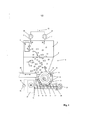
[00027] Na figura 1 um dispositivo de acordo com a invenção para atrituração de detrito de plástico em um desenho esquemático em corte pelo lado; e na figura 2, um detalhe do dispositivo na área do equipamento de trituração, em uma vista esquemática de cima.[00027] In figure 1 a device according to the invention for crushing plastic debris in a schematic drawing in section from the side; and in figure 2, a detail of the device in the area of the crushing equipment, in a schematic view from above.
[00028] Na figura 1 está representado o dispositivo 1 para a trituração de produto 2 plástico, abrangendo um recipiente 3 para a recepção do produto plástico 2 embalado, em particular, solto e um equipamento de trituração 4 se projetando para dentro do recipiente 3 ou disposto nele, para a trituração do produto plástico e de seu transporte para uma abertura de descarga 5, caracterizado por entradas de ar 6 na área do equipamento de trituração 4, e por entradas de ar 7 na parede do recipiente 8.[00028] Figure 1 shows the
[00029] Para a melhor vista geral, na figura 1 o dispositivo 1 está representado em uma vista em corte do lado, sendo que, o plano de corte escolhido fica verticalmente no centro do dispositivo 1. Com isso é possibilitada uma vista no interior do dispositivo1. A abertura 9 se encontra na área da parede do recipiente 8.[00029] For the best general view, in Figure 1,
[00030] O produto plástico 2 úmido consegue chegar por fora, por meio de esteira transportadora ou de um outro dispositivo de transporte, por exemplo, pneumático, que não está representado na figura 1, e que também não pertence ao dispositivo 1 de acordo com a invenção, através de uma abertura 9 no recipiente 3 do dispositivo 1. A abertura 9 encontra-se na área da parede do recipiente 8.[00030] The wet plastic product 2 is able to arrive from the outside, using a conveyor belt or another transport device, for example, pneumatic, which is not shown in figure 1, and which does not belong to
[00031] Em virtude da força centrífuga, o produto plástico 2 úmido no recipiente 3 iria chegar diretamente ao equipamento de trituração 4 na direção da seta 10 para baixo, e ali iria ficar sobreposto um ao outro rente. Com isso seria incluída também a umidade residual, que ainda está aderente ao produto plástico, uma secagem do produto plástico seria possível somente de modo insuficiente. Além disso, o produto plástico que está sobreposto possivelmente iria bloquear a fenda 11, que se encontra entre o corpo do rotor 12 ou as facas 13 fixadas nele, e as facas 15 verticais, sendo que, o corpo do rotor 12 gira na direção de rotação, com isso, o produto plástico 2 não poderia chegar ao equipamento de trituração 4 e, com isso, uma operação sem interferências não seria assegurada.[00031] Due to the centrifugal force, the wet plastic product 2 in the container 3 would reach directly to the crushing
[00032] Por isso, a invenção é caracterizada por entradas de ar 6 na área do equipamento de trituração 4, representadas na figura 1 como entradas de ar 6 na parede de revestimento 18, sendo que, o ar é conduzido de um aparelho de produção de ar comprimido 16 através de condutores, para as entradas de ar 6 e, então, de modo visado para o espaço da fenda 17 entre a parede de revestimento 18, que está disposta em um intervalo da pista de circulação das facas 13 do corpo do rotor 12, e é introduzido pelo bocal no corpo do rotor 12. Neste caso, o ar que consegue chegar através das entradas de ar 6, de preferência, seco, ao equipamento de trituração 4, no espaço da fenda 17 principalmente na direção de rotação 14 do corpo do rotor 12 e, com isso, é conduzido na direção de transporte do produto plástico 2, e por conseguinte, através da corrente de convecção no espaço da fenda 17 a umidade é transportada pelo produto plástico 2, e é evitada uma formação de condensado na parede de revestimento 18, bem como, no corpo do rotor 12.[00032] Therefore, the invention is characterized by
[00033] O aparelho de produção de ar comprimido 16 é executado, de preferência, como compressor de canal lateral.[00033] The compressed air generating device 16 is preferably used as a side channel compressor.
[00034] O volume principal do ar soprado flui na direção de rotação 14 ao longo do corpo do rotor 12, através do espaço da fenda 17, até que ele consiga chegar no espaço interno do recipiente 3, na fenda de saída 19 que fica oposta, a qual porém, é formada por uma ou por várias facas 15 verticais, e pelas facas 13 girando, fixadas no corpo do rotor 12. Uma corrente parcial menor do ar soprado consegue chegar, ao contrário da direção de rotação 14 do corpo do rotor 12 e, com isso, ao contrário da direção de transporte do produto plástico 2, dentro do equipamento de trituração 4 através da fenda 11 no interior do recipiente 3 e, neste caso, solta o produto plástico 2 que, em todo caso, está na área da fenda 11. Uma outra corrente parcial do ar soprado através das entradas de ar 6 deixa o espaço da fenda 17, através da abertura de descarga 5 e, com isso, consegue chegar junto com o produto plástico triturado no fuso de dosagem 20 e, então, adiante para o fuso do dispositivo de extrusão 21, que transporta o produto plástico para o dispositivo de extrusão seguinte, não representado.[00034] The main volume of the blown air flows in the direction of rotation 14 along the
[00035] No interior do recipiente 3 o ar sobe do equipamento de trituração 4 na direção da seta 22 para cima. A velocidade de corrente do ar no interior do recipiente 3 é escolhida de tal modo que, o produto plástico 2 entregue com menor velocidade na contracorrente na direção da seta 10 diminui para baixo para o equipamento de trituração 4 e, neste caso, é seco pela corrente de ar que sobe. Partículas deplástico muito leves ou extensas, neste caso, devem serdescarregadas do recipiente 3.[00035] Inside the container 3, the air rises from the crushing
[00036] De forma apropriada para isso está prevista uma tampa de cobertura correspondente, na área da abertura 9 para a alimentação de plástico, que é executada, por exemplo, como peneira fina ou fluxo, e está adaptada ao dispositivo de transporte não representado, e impede a saída de partículas de plástico muito pequenas do dispositivo 1, ou através de fendas entre o dispositivo 1 e o dispositivo de transporte, para a alimentação do produto plástico. Uma tampa de cobertura desse tipo não está representada na figura 1.[00036] Appropriately for this purpose, a corresponding cover cover is provided in the area of
[00037] O ar úmido ou o vapor é transportado na parte superior do recipiente 3 através de entradas de ar 7 na parede do recipiente 8, para fora do dispositivo 1 para o ambiente. Na figura 1 essas entradas de ar 7 estão conectadas a um aparelho de aspiração de vapor 23. O aparelho de aspiração de vapor é executado, de preferência, como ventilador radial 25, sendo que, na figura 1 estão representadas duas entradas de ar 7 com, respectivamente, um ventilador radial 25 próprio.[00037] Moist air or steam is transported in the upper part of the container 3 through air intakes 7 in the wall of the container 8, out of the
[00038] Além disso, na figura 1 horizontalmente na área inferior do recipiente 3 está prevista uma corrediça de vedação 26. Com auxílio da corrediça de vedação 26, que é movimentada na direção horizontal para frente e novamente para trás, o produto plástico 2 é conduzido de modo confiável para a fenda 11. Além disso, a figura 1 mostra o acionamento 27 do fuso de dosagem 20.[00038] Furthermore, in figure 1 horizontally in the lower area of the container 3, a sealing slide 26 is provided. With the aid of the sealing slide 26, which is moved in the horizontal direction forwards and backwards, the plastic product 2 is reliably driven into
[00039] A figura 2 mostra um detalhe do dispositivo 1 na área do equipamento de trituração 4, em uma vista esquemática de cima. Neste caso, a parede de revestimento 18, que envolve o corpo do rotor 12 não representado aqui, está representada com várias entradas de ar 6. Através das setas 22 está indicada a direção de corrente do ar soprado ou a direção de transporte do produto plástico 2 triturado. A parede de revestimento 18, como mostra a figura 2, pode ser perfilada, por exemplo, por estrias ou tramas, pelo que o produto plástico 2 no espaço da fenda 17, é empurrado junto através das estrias ou tramas na direção da abertura de descarga 5 disposta no centro, e dali consegue chegar ao fuso de dosagem 20. Além disso, na figura 2 está representado o acionamento 27 do fuso de dosagem 20, bem como, o outro fuso do dispositivo de extrusão 21 colocado no ângulo, para isso, com seu acionamento 28. Os dois fusos de transporte 20 e 21 estão representados cortados horizontalmente para o melhor entendimento.[00039] Figure 2 shows a detail of
Claims (6)
Applications Claiming Priority (3)
| Application Number | Priority Date | Filing Date | Title |
|---|---|---|---|
| AT0018509A AT507856B1 (en) | 2009-02-03 | 2009-02-03 | DEVICE FOR CRUSHING PLASTIC |
| ATA185/2009 | 2009-02-03 | ||
| PCT/EP2010/050439 WO2010089174A1 (en) | 2009-02-03 | 2010-01-15 | Device for reducing plastic |
Publications (2)
| Publication Number | Publication Date |
|---|---|
| BRPI1008809A2 BRPI1008809A2 (en) | 2016-08-09 |
| BRPI1008809B1 true BRPI1008809B1 (en) | 2021-03-09 |
Family
ID=42122994
Family Applications (1)
| Application Number | Title | Priority Date | Filing Date |
|---|---|---|---|
| BRPI1008809-1A BRPI1008809B1 (en) | 2009-02-03 | 2010-01-15 | device for crushing plastic product |
Country Status (8)
| Country | Link |
|---|---|
| US (1) | US20120037739A1 (en) |
| EP (1) | EP2393598B1 (en) |
| JP (1) | JP5650665B2 (en) |
| AT (1) | AT507856B1 (en) |
| BR (1) | BRPI1008809B1 (en) |
| ES (1) | ES2743299T3 (en) |
| PL (1) | PL2393598T3 (en) |
| WO (1) | WO2010089174A1 (en) |
Families Citing this family (5)
| Publication number | Priority date | Publication date | Assignee | Title |
|---|---|---|---|---|
| US10725451B2 (en) * | 2013-10-21 | 2020-07-28 | Made In Space, Inc. | Terrestrial and space-based manufacturing systems |
| AT517755A1 (en) * | 2015-09-22 | 2017-04-15 | Next Generation Recyclingmaschinen Gmbh | Apparatus and method for processing thermoplastic with an improved shredding / transporting device |
| AT517756B1 (en) * | 2015-09-22 | 2017-11-15 | Next Generation Recyclingmaschinen Gmbh | Apparatus and method for processing thermoplastic with a blowing device for a screw conveyor |
| CN107115934B (en) * | 2016-10-26 | 2022-09-20 | 宁波意菲特机械制造有限公司 | Double-end interactive crushing efficient shredder |
| AT523082B1 (en) * | 2019-10-16 | 2022-07-15 | Pureloop Gesmbh | Device for processing material, in particular plastic material |
Family Cites Families (16)
| Publication number | Priority date | Publication date | Assignee | Title |
|---|---|---|---|---|
| US3960334A (en) * | 1975-02-24 | 1976-06-01 | Cumberland Engineering Company, Inc. | Size reduction apparatus |
| DE2609850A1 (en) * | 1976-03-10 | 1977-09-15 | Weiss Gmbh & Co Kg Maschinen F | Disintegrating and sintering thin thermoplastic waste - by using frictional heat from rotating cutters plus hot air current |
| DE3543370A1 (en) * | 1985-12-07 | 1987-06-11 | Jackering Altenburger Masch | MILL WITH SEVERAL GRINDINGS |
| JPS62282654A (en) * | 1986-05-30 | 1987-12-08 | マテックス株式会社 | Force feeder for runner ground product |
| DE9202161U1 (en) | 1992-02-20 | 1992-04-09 | Schmoll, Heinz, 6242 Kronberg | Device for shredding empty plastic oil canisters |
| US5402948A (en) * | 1993-04-30 | 1995-04-04 | Kaczmarek; Al | Comminuting device with face |
| JPH07150492A (en) * | 1993-11-30 | 1995-06-13 | Mitsubishi Heavy Ind Ltd | Device for compression-molding waste paper and sheet disintegrator and cutter |
| DE4425765C2 (en) * | 1994-07-21 | 1999-01-07 | Duerr Systems Gmbh | System for cleaning workpieces using a compressed air jet |
| US5556039A (en) * | 1994-10-28 | 1996-09-17 | Nissei Plastic Industrial Co., Ltd. | Crushing machine apparatus and a method for cleaning the crushing machine apparatus |
| JPH08257428A (en) * | 1995-03-22 | 1996-10-08 | Fuji Photo Film Co Ltd | Pulverizer for photographic processing composition container |
| JP2001190979A (en) * | 2001-03-15 | 2001-07-17 | Taisei Jushi:Kk | High speed rotating crusher |
| US6749138B2 (en) * | 2002-03-05 | 2004-06-15 | Phoenix Technologies, L.P. | Granulator |
| US7077344B2 (en) * | 2002-03-12 | 2006-07-18 | Starlinger & Co. Gesellschaft M.B.H. | Device for the comminution of materials |
| DE102005003849B3 (en) * | 2005-01-27 | 2006-04-20 | Daimlerchrysler Ag | Ventilated seat for vehicle has ventilation layer integrated into upholstery in order to ventilate it |
| AT503390B1 (en) | 2006-03-30 | 2008-06-15 | Erema | DEVICE FOR DRYING WET BREAKABLE GOOD, PREFERABLY OF PLASTIC PARTICLES |
| AT504854B1 (en) * | 2007-02-15 | 2012-08-15 | Erema | METHOD AND DEVICE FOR PREPARING A MATERIAL |
-
2009
- 2009-02-03 AT AT0018509A patent/AT507856B1/en not_active IP Right Cessation
-
2010
- 2010-01-15 PL PL10701493T patent/PL2393598T3/en unknown
- 2010-01-15 BR BRPI1008809-1A patent/BRPI1008809B1/en active IP Right Grant
- 2010-01-15 ES ES10701493T patent/ES2743299T3/en active Active
- 2010-01-15 JP JP2011548630A patent/JP5650665B2/en active Active
- 2010-01-15 EP EP10701493.8A patent/EP2393598B1/en active Active
- 2010-01-15 WO PCT/EP2010/050439 patent/WO2010089174A1/en active Application Filing
- 2010-01-15 US US13/146,914 patent/US20120037739A1/en not_active Abandoned
Also Published As
| Publication number | Publication date |
|---|---|
| US20120037739A1 (en) | 2012-02-16 |
| PL2393598T3 (en) | 2019-12-31 |
| AT507856A2 (en) | 2010-08-15 |
| ES2743299T3 (en) | 2020-02-18 |
| JP2012516771A (en) | 2012-07-26 |
| EP2393598A1 (en) | 2011-12-14 |
| BRPI1008809A2 (en) | 2016-08-09 |
| WO2010089174A1 (en) | 2010-08-12 |
| EP2393598B1 (en) | 2019-05-29 |
| AT507856A3 (en) | 2011-08-15 |
| JP5650665B2 (en) | 2015-01-07 |
| AT507856B1 (en) | 2011-09-15 |
Similar Documents
| Publication | Publication Date | Title |
|---|---|---|
| US10449544B2 (en) | Apparatus and process for demanufacturing materials from composite manufactures | |
| RU2461459C2 (en) | Method and device for primary processing of materials | |
| US6527206B1 (en) | Method for processing mixed waste, processing plant and buffer silos therefor | |
| BRPI1008809B1 (en) | device for crushing plastic product | |
| CN105722610A (en) | Method and device for separating particles of plastic foil and particles of organic material | |
| JP2010536575A (en) | Equipment for drying and cleaning small pieces | |
| KR101595155B1 (en) | Processing apparatus for grinding and recycling synthetic resin waste | |
| US20130174517A1 (en) | Carpet Recycling Method | |
| KR101662767B1 (en) | Apparatus for Delaminating Paint from Waste | |
| KR101488150B1 (en) | Manufacturing method and device of recycling resin chip by using waste scrap | |
| EP4070928A1 (en) | Apparatus for loading fragments of thermoplastic film in an extruder, particularly for recycling thermoplastic material, and operating method thereof | |
| KR102335848B1 (en) | Waste synthetic resin sorting system | |
| JP3410973B2 (en) | Dust separation device | |
| KR101294029B1 (en) | separating apparatus of wasted electric wire | |
| JP3631955B2 (en) | Washing and dewatering machine and recycling equipment for strips such as recovered paper cups and milk cartons | |
| US2499457A (en) | Continuous centrifugal drier | |
| JP7418783B2 (en) | Separation device | |
| CA2763399A1 (en) | Carpet reclamation system | |
| JP3764698B2 (en) | Paper pack separator | |
| KR101838263B1 (en) | Centrifugation type dehydrator for crushed material | |
| CN107756669A (en) | A kind of plastics granulator with drying function | |
| CN210281619U (en) | Spin dryer chip supply separator with part separation function | |
| US4453676A (en) | Shredding machine with washer and drier | |
| CN210252724U (en) | Metal cutting centrifugal drier | |
| JP6958930B2 (en) | Waste plastic water flow type debris supply device |
Legal Events
| Date | Code | Title | Description |
|---|---|---|---|
| B06F | Objections, documents and/or translations needed after an examination request according [chapter 6.6 patent gazette] | ||
| B06U | Preliminary requirement: requests with searches performed by other patent offices: procedure suspended [chapter 6.21 patent gazette] | ||
| B09A | Decision: intention to grant [chapter 9.1 patent gazette] | ||
| B16A | Patent or certificate of addition of invention granted [chapter 16.1 patent gazette] |
Free format text: PRAZO DE VALIDADE: 10 (DEZ) ANOS CONTADOS A PARTIR DE 09/03/2021, OBSERVADAS AS CONDICOES LEGAIS. |