EP2049720B1 - Procédé de fabrication d'articles filtrants profilés - Google Patents
Procédé de fabrication d'articles filtrants profilés Download PDFInfo
- Publication number
- EP2049720B1 EP2049720B1 EP07872252.7A EP07872252A EP2049720B1 EP 2049720 B1 EP2049720 B1 EP 2049720B1 EP 07872252 A EP07872252 A EP 07872252A EP 2049720 B1 EP2049720 B1 EP 2049720B1
- Authority
- EP
- European Patent Office
- Prior art keywords
- fiber
- web
- size
- fibers
- orifices
- Prior art date
- Legal status (The legal status is an assumption and is not a legal conclusion. Google has not performed a legal analysis and makes no representation as to the accuracy of the status listed.)
- Not-in-force
Links
Images

Classifications
-
- D—TEXTILES; PAPER
- D04—BRAIDING; LACE-MAKING; KNITTING; TRIMMINGS; NON-WOVEN FABRICS
- D04H—MAKING TEXTILE FABRICS, e.g. FROM FIBRES OR FILAMENTARY MATERIAL; FABRICS MADE BY SUCH PROCESSES OR APPARATUS, e.g. FELTS, NON-WOVEN FABRICS; COTTON-WOOL; WADDING ; NON-WOVEN FABRICS FROM STAPLE FIBRES, FILAMENTS OR YARNS, BONDED WITH AT LEAST ONE WEB-LIKE MATERIAL DURING THEIR CONSOLIDATION
- D04H3/00—Non-woven fabrics formed wholly or mainly of yarns or like filamentary material of substantial length
- D04H3/02—Non-woven fabrics formed wholly or mainly of yarns or like filamentary material of substantial length characterised by the method of forming fleeces or layers, e.g. reorientation of yarns or filaments
-
- A—HUMAN NECESSITIES
- A62—LIFE-SAVING; FIRE-FIGHTING
- A62B—DEVICES, APPARATUS OR METHODS FOR LIFE-SAVING
- A62B18/00—Breathing masks or helmets, e.g. affording protection against chemical agents or for use at high altitudes or incorporating a pump or compressor for reducing the inhalation effort
- A62B18/02—Masks
-
- B—PERFORMING OPERATIONS; TRANSPORTING
- B01—PHYSICAL OR CHEMICAL PROCESSES OR APPARATUS IN GENERAL
- B01D—SEPARATION
- B01D39/00—Filtering material for liquid or gaseous fluids
- B01D39/14—Other self-supporting filtering material ; Other filtering material
- B01D39/16—Other self-supporting filtering material ; Other filtering material of organic material, e.g. synthetic fibres
- B01D39/1607—Other self-supporting filtering material ; Other filtering material of organic material, e.g. synthetic fibres the material being fibrous
- B01D39/1623—Other self-supporting filtering material ; Other filtering material of organic material, e.g. synthetic fibres the material being fibrous of synthetic origin
- B01D39/163—Other self-supporting filtering material ; Other filtering material of organic material, e.g. synthetic fibres the material being fibrous of synthetic origin sintered or bonded
-
- D—TEXTILES; PAPER
- D01—NATURAL OR MAN-MADE THREADS OR FIBRES; SPINNING
- D01D—MECHANICAL METHODS OR APPARATUS IN THE MANUFACTURE OF ARTIFICIAL FILAMENTS, THREADS, FIBRES, BRISTLES OR RIBBONS
- D01D5/00—Formation of filaments, threads, or the like
- D01D5/08—Melt spinning methods
- D01D5/082—Melt spinning methods of mixed yarn
-
- D—TEXTILES; PAPER
- D01—NATURAL OR MAN-MADE THREADS OR FIBRES; SPINNING
- D01D—MECHANICAL METHODS OR APPARATUS IN THE MANUFACTURE OF ARTIFICIAL FILAMENTS, THREADS, FIBRES, BRISTLES OR RIBBONS
- D01D5/00—Formation of filaments, threads, or the like
- D01D5/08—Melt spinning methods
- D01D5/098—Melt spinning methods with simultaneous stretching
- D01D5/0985—Melt spinning methods with simultaneous stretching by means of a flowing gas (e.g. melt-blowing)
-
- D—TEXTILES; PAPER
- D04—BRAIDING; LACE-MAKING; KNITTING; TRIMMINGS; NON-WOVEN FABRICS
- D04H—MAKING TEXTILE FABRICS, e.g. FROM FIBRES OR FILAMENTARY MATERIAL; FABRICS MADE BY SUCH PROCESSES OR APPARATUS, e.g. FELTS, NON-WOVEN FABRICS; COTTON-WOOL; WADDING ; NON-WOVEN FABRICS FROM STAPLE FIBRES, FILAMENTS OR YARNS, BONDED WITH AT LEAST ONE WEB-LIKE MATERIAL DURING THEIR CONSOLIDATION
- D04H3/00—Non-woven fabrics formed wholly or mainly of yarns or like filamentary material of substantial length
- D04H3/016—Non-woven fabrics formed wholly or mainly of yarns or like filamentary material of substantial length characterised by the fineness
-
- D—TEXTILES; PAPER
- D04—BRAIDING; LACE-MAKING; KNITTING; TRIMMINGS; NON-WOVEN FABRICS
- D04H—MAKING TEXTILE FABRICS, e.g. FROM FIBRES OR FILAMENTARY MATERIAL; FABRICS MADE BY SUCH PROCESSES OR APPARATUS, e.g. FELTS, NON-WOVEN FABRICS; COTTON-WOOL; WADDING ; NON-WOVEN FABRICS FROM STAPLE FIBRES, FILAMENTS OR YARNS, BONDED WITH AT LEAST ONE WEB-LIKE MATERIAL DURING THEIR CONSOLIDATION
- D04H3/00—Non-woven fabrics formed wholly or mainly of yarns or like filamentary material of substantial length
- D04H3/08—Non-woven fabrics formed wholly or mainly of yarns or like filamentary material of substantial length characterised by the method of strengthening or consolidating
- D04H3/14—Non-woven fabrics formed wholly or mainly of yarns or like filamentary material of substantial length characterised by the method of strengthening or consolidating with bonds between thermoplastic yarns or filaments produced by welding
-
- D—TEXTILES; PAPER
- D04—BRAIDING; LACE-MAKING; KNITTING; TRIMMINGS; NON-WOVEN FABRICS
- D04H—MAKING TEXTILE FABRICS, e.g. FROM FIBRES OR FILAMENTARY MATERIAL; FABRICS MADE BY SUCH PROCESSES OR APPARATUS, e.g. FELTS, NON-WOVEN FABRICS; COTTON-WOOL; WADDING ; NON-WOVEN FABRICS FROM STAPLE FIBRES, FILAMENTS OR YARNS, BONDED WITH AT LEAST ONE WEB-LIKE MATERIAL DURING THEIR CONSOLIDATION
- D04H3/00—Non-woven fabrics formed wholly or mainly of yarns or like filamentary material of substantial length
- D04H3/08—Non-woven fabrics formed wholly or mainly of yarns or like filamentary material of substantial length characterised by the method of strengthening or consolidating
- D04H3/16—Non-woven fabrics formed wholly or mainly of yarns or like filamentary material of substantial length characterised by the method of strengthening or consolidating with bonds between thermoplastic filaments produced in association with filament formation, e.g. immediately following extrusion
-
- B—PERFORMING OPERATIONS; TRANSPORTING
- B01—PHYSICAL OR CHEMICAL PROCESSES OR APPARATUS IN GENERAL
- B01D—SEPARATION
- B01D2239/00—Aspects relating to filtering material for liquid or gaseous fluids
- B01D2239/06—Filter cloth, e.g. knitted, woven non-woven; self-supported material
- B01D2239/0604—Arrangement of the fibres in the filtering material
- B01D2239/064—The fibres being mixed
Definitions
- Patents or applications relating to nonwoven webs, their manufacture and articles made therefrom include U.S. Patent Nos. 3,981,650 (Page ), 4,100,324 (Anderson ), 4,118,531 (Hauser ), 4,536,440 (Berg ), 4,547,420 (Krueger et al ), 4,818,464 (Lau ), 4,931,355 (Radwanski et al. ), 4,988,560 (Meyer et al. ), 5,227,107 (Dickenson et al. ), 5,374,458 (Burgio ) 5,382,400 (Pike et al.
- EP 0 322 136 B1 Minnesota Mining and Manufacturing Co.
- Japanese published application Nos. JP 2001-049560 Non-Resin Motor Co. Ltd.
- JP 2002-180331 Choisso Corp. '331
- JP 2002-348737 Choisso Corp. '737
- U.S. Patent Application Publication Nos. US2004/0097155 A1 Olson et al .
- US2005/0217226 A1 (Sundet et al. '226 ).
- Document WO 96/03194 discloses a method of preparing a melt-blown fibrous non-woven web comprising extruding molten resin from two parallel rows of linearly arranged, substantially equally spaced nozzles to form fibers onto the surface of a cylindrical collector having a longitudinal axis arranged parallel to the rows of nozzles, wherein the rows of nozzles are offset from each other and are angled toward each other.
- the method provides a melt-blown fibrous non-woven web, which is substantially uniform, having a closely controlled average fiber diameter, with a narrow distribution of fiber diameters and a uniform weight distribution.
- Document JP 200 224 069 A discloses a method of manufacturing nonwoven fabric filter consisting of a mixed fibers comprising different kind of polymers. Different polymers are extruded simultaneously from different nozzles arranged on a same die. Melt spinning is carried out from a different nozzle arranged by the same die.
- the filaments discharged from the nozzles are cooled and extended by high-speed air flow, and is deposited on an uptake conveyor, and a nonwoven fabric web is formed.
- a melt blown nonwoven fabric is manufactured using 2 type of polypropylenes in which molecular weights were different.
- the melt blown nonwoven fabric of a monolayer in which two kinds of fibers had a difference in a molecular weight was distributed minutely, and the air permeability of the nonwoven fabric could be controlled freely.
- Shaped filtration articles such as molded respirators or pleated furnace filters are sometimes made using nonwoven webs made from multicomponent (e.g., bicomponent) fibers.
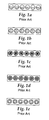
- Fig. 1a through Fig. 1e depict five popular bicomponent fiber configurations, which may be referred to respectively as “2-layer” or “side-by-side” ( Fig. 1a ), “islands in the sea” ( Fig. 1b ), “solid segmented pie” ( Fig. 1c ), “hollow segmented pie” ( Fig. 1d ) and “sheath-core” ( Fig. 1e ).
- the use of two or more polymers in a multicomponent fiber limits the extent to which unused portions of the multicomponent fiber web or article may be recycled, and if only one polymer is electret chargeable may limit the extent to which charge may be applied.
- Shaped filtration articles may also be formed by adding an extraneous bonding material (e.g., an adhesive) to a filtration web, with consequent limitations due to the chemical or physical nature of the added bonding material including added web basis weight and loss of recyclability.
- an extraneous bonding material e.g., an adhesive
- the present invention provides, in one aspect, a method for making shaped filtration articles, which method comprises:
- the disclosed method has a number of beneficial and unique properties.
- a web with well-mixed fibers can be obtained.
- Both the larger size fibers and the microfibers may be highly charged.
- the larger size fibers can impart improved moldability and improved stiffness to a molded or shaped matrix made from the disclosed web.
- the microfibers can impart increased fiber surface area to the web, with beneficial effects such as improved filtration performance. By using microfibers and larger size fibers of different sizes, filtration and molding properties can be tailored to a particular use.
- microfiber webs In contrast to the high pressure drop (and thus high breathing resistance) often characteristic of microfiber webs, pressure drops of the disclosed nonwoven webs are kept lower, because the larger fibers physically separate and space apart the microfibers.
- the microfibers and larger size fibers also appear to cooperate with one another to provide a higher particle depth loading capacity.
- the disclosed nonwoven webs can be quite economically prepared. Also, if the microfibers and larger size fibers all have the same polymeric composition and extraneous bonding materials are not employed, unused portions of the disclosed nonwoven webs can be fully recycled.
- Fig. 1a through Fig. 1e respectively show cross-sectional schematic views of several bicomponent fiber configurations
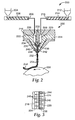
- Fig. 2 is a schematic cross-sectional view and Fig. 3 is an outlet end view of an exemplary meltblowing die having a row of orifices supplied with polymers of the same polymeric composition flowing at different rates or with different viscosities;
- Fig. 4 is a perspective view, partially in section, of a disposable personal respirator having a deformation-resistant cup-shaped porous monolayer matrix disposed between inner and outer cover layers;
- Fig. 5 is a perspective view of pleated filtration media
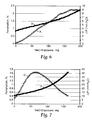
- Fig. 6 is a graph showing % NaCl penetration and pressure drop for the molded respirator of Run No. 3-1M and Fig. 7 is a similar graph for a commercial N95 respirator made from multilayer filtration media;
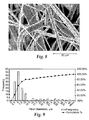
- Fig. 8 and Fig. 9 respectively are a photomicrograph of and a histogram of fiber count (frequency) vs. fiber size in ⁇ m for the Run No. 3-1M molded matrix.
- porous means air-permeable.
- the term "monocomponent" when used with respect to a fiber or collection of fibers means fibers formed from one polymer only. This is not meant to exclude fibers formed from one polymer to which small amounts of additives have been added for purposes such as electret charging enhancement, antistatic properties, lubrication, hydrophilicity, coloration, etc. These additives, e.g. tristearyl melamine for charging enhancement, are generally present in an amount less than about 5 wt. % and more typically less than about 2 wt. %.
- the term "of the same polymeric composition” means polymers that have essentially the same repeating molecular unit, but which may differ in molecular weight, melt index, method of manufacture, commercial form, etc., and which may optionally contain minor amounts (e.g., less than about 3 wt. %) of an electret charging additive.
- size when used with respect to a filament or fiber means the filament or fiber diameter for a filament or fiber having a circular cross section, or the length of the longest cross-sectional chord that may be constructed across a filament or fiber having a non-circular cross-section.
- continuous when used with respect to a fiber or collection of fibers means fibers having an essentially infinite aspect ratio (viz., a ratio of length to size of e.g., at least about 10,000 or more).
- Effective Fiber Diameter when used with respect to a collection of fibers means the value determined according to the method set forth in Davies, C. N., "The Separation of Airborne Dust and Particles", Institution of Mechanical Engineers, London, Proceedings 1B, 1952 for a web of fibers of any cross-sectional shape be it circular or non-circular.
- mode when used with respect to a histogram of mass fraction vs. fiber size in ⁇ m or a histogram of fiber count (frequency) vs. fiber size in ⁇ m means a local peak whose height is larger than that for fiber sizes 1 and 2 ⁇ m smaller and 1 and 2 ⁇ m larger than the local peak.
- bimodal mass fraction/fiber size mixture means a collection of fibers having a histogram of mass fraction vs. fiber size in ⁇ m exhibiting at least two modes.
- a bimodal mass fraction/fiber size mixture may include more than two modes, for example it may be a trimodal or higher-modal mass fraction/fiber size mixture.
- bimodal fiber count/fiber size mixture means a collection of fibers having a histogram of fiber count (frequency) vs. fiber size in ⁇ m exhibiting at least two modes whose corresponding fiber sizes differ by at least 50% of the smaller fiber size.
- a bimodal fiber count/fiber size mixture may include more than two modes, for example it may be a trimodal or higher-modal fiber count/fiber size mixture.
- nonwoven web means a fibrous web characterized by entanglement or point bonding of the fibers.
- the term "monolayer matrix" when used with respect to a nonwoven web containing a bimodal mass fraction/fiber size mixture of fibers means having (other than with respect to fiber size) a generally uniform distribution of similar fibers throughout a cross-section of the web, and having (with respect to fiber size) fibers representing each modal population present throughout a cross-section of the web.
- Such a monolayer matrix may have a generally uniform distribution of fiber sizes throughout a cross-section of the web or may, for example, have a depth gradient of fiber sizes such as a preponderance of larger size fibers proximate one major face of the web and a preponderance of microfibers proximate the other major face of the web.
- Attenuating the filaments into fibers means the conversion of a segment of a filament into a segment of greater length and smaller size.
- meltblown when used with respect to a nonwoven web means a web formed by extruding a fiber-forming material through a plurality of orifices to form filaments while contacting the filaments with air or other attenuating fluid to attenuate the filaments into fibers and thereafter collecting a layer of the attenuated fibers.
- meltblown fibers means fibers prepared by extruding molten fiber-forming material through orifices in a die into a high-velocity gaseous stream (e.g., a single stream or a plurality of converging streams), where the extruded material is first attenuated and then solidifies as a mass of fibers.
- a high-velocity gaseous stream e.g., a single stream or a plurality of converging streams
- meltblown fibers have sometimes been reported to be discontinuous, the fibers generally are long and entangled sufficiently that it is usually not possible to remove one complete meltblown fiber from a mass of such fibers or to trace one meltblown fiber from beginning to end.
- meltblowing die means a die for use in a meltblowing process.
- microfibers means fibers having a median size (as determined using microscopy) of 10 ⁇ m or less; "ultrafine microfibers” means microfibers having a median size of two ⁇ m or less; and "submicron microfibers” means microfibers having a median size one ⁇ m or less.
- an array of submicron microfibers it means the complete population of microfibers in that array, or the complete population of a single batch of microfibers, and not only that portion of the array or batch that is of submicron dimensions.
- charged when used with respect to a collection of fibers means fibers that exhibit at least a 50% loss in Quality Factor QF (discussed below) after being exposed to a 20 Gray absorbed dose of 1 mm beryllium-filtered 80 KVp X-rays when evaluated for percent dioctyl phthalate (% DOP) penetration at a face velocity of 7 cm/sec.
- QF Quality Factor
- self-supporting means an article having sufficient coherency and strength so as to be handleable using reel-to-reel manufacturing equipment without substantial tearing or rupture.
- Fig. 2 and Fig. 3 illustrate an apparatus 200 for making a porous monocomponent nonwoven web containing a bimodal fiber count/fiber size mixture of intermingled continuous microfibers and larger size fibers of the same polymeric composition.
- Meltblowing die 202 is supplied with a first liquefied fiber-forming material fed from hopper 204 , extruder 206 and conduit 208 at a first flow rate or first viscosity.
- Die 202 is separately supplied with a second liquefied fiber-forming material of the same polymeric composition fed from hopper 212 , extruder 214 and conduit 216 at a second, different flow rate or viscosity.
- the conduits 208 and 216 are in respective fluid communication with first and second die cavities 218 and 220 located in first and second generally symmetrical parts 222 and 224 which form outer walls for die cavities 218 and 220 .
- First and second generally symmetrical parts 226 and 228 form inner walls for die cavities 218 and 220 and meet at seam 230. Parts 226 and 228 may be separated along most of their length by insulation 232 .
- Deflector plates 240 and 242 direct streams of attenuating fluid (e.g., heated air) so that they converge on an array of filaments 252 issuing from meltblowing die 202 and attenuate the filaments 252 into fibers 254 .
- the fibers 254 land against porous collector 256 and form a self-supporting nonwoven meltblown web 258 .
- Fig.3 shows meltblowing die 202 in outlet end perspective view, with the attenuating gas deflector plates 240 and 242 removed. Parts 222 and 224 meet along seam 244 in which is located a first set of orifices 246 and a second set of orifices 248 and through which the array of filaments 252 will emerge. Die cavities 218 and 220 are in respective fluid communication via passages 234 , 236 and 238 with the first set of orifices 246 and second set of orifices 248 .
- the apparatus shown in Fig. 2 and Fig. 3 may be operated in several modes or modified in several ways to provide a stream of larger size fibers issuing from one die cavity and smaller size fibers issuing from the other die cavity and thereby form a nonwoven web containing a bimodal mass fraction/fiber size mixture of intermingled larger size fibers and smaller size fibers of the same polymeric composition.
- an identical polymer may be supplied from extruder 206 to die cavity 218 and from extruder 214 to die cavity 220 , with extruder 214 providing a greater polymer flow rate (e.g., through the use of a larger diameter extruder barrel or higher rotational speed) or operating at a lower temperature than extruder 206 so as to supply the polymer at a lesser flow rate or viscosity into die cavity 218 and a greater flow rate or viscosity into die cavity 220 and produce smaller size fibers from orifices 246 and larger size fibers from orifices 248 .
- extruder 214 providing a greater polymer flow rate (e.g., through the use of a larger diameter extruder barrel or higher rotational speed) or operating at a lower temperature than extruder 206 so as to supply the polymer at a lesser flow rate or viscosity into die cavity 218 and a greater flow rate or viscosity into die cavity 220 and produce smaller size fibers from orifices 246 and
- Die cavity 218 may be operated at a high temperature and die cavity 220 may be operated at a low temperature so as to produce smaller size fibers from orifices 246 and larger size fibers from orifices 248 .
- Polymers of the same polymeric composition but different melt indices may be supplied from extruder 206 to die cavity 218 and from extruder 214 to die cavity 220 (using for example a high melt index version of the polymer in extruder 206 and a low melt index of the same polymer in extruder 214 so as to produce smaller size fibers from orifices 246 and larger size fibers from orifices 248 ).
- the orifices 246 and 248 are arranged in alternating order in a single row across the outlet end of die 202 , and in respective fluid communication in a 1:1 ratio with the die cavities 218 and 220 .
- Other arrangements of the orifices and other ratios of the numbers of orifices 246 and 248 may be employed to provide nonwoven webs with altered fiber size distributions.
- the orifices may be arranged in a plurality of rows (e.g., 2, 3, 4 or more rows) between the attenuating air outlets. Patterns other than rows may be employed if desired, e.g., randomly-located orifices.
- each row may contain orifices from only one set or from both the first and second sets.
- the number of orifices in the first and second set may stand in a variety of ratios, e.g., 10:90, 20:80, 30:70, 40:60, 50:50, 60:40, 70:30, 80:20, 90:10 and other ratios depending on the desired web structure.
- the first and second set orifices need not alternate and instead may be arranged in any desired fashion, e.g., 1221, 1122211, 11112221111 and other arrangements depending on the desired web structure.
- the die tip may contain more than one set of orifices, e.g., first, second, third and if need be further sets of orifices in respective fluid communication with first, second, third and if need be further die cavities within the meltblowing die so as to obtain a web with a tri- or greater-modal distribution of fiber sizes.
- meltblowing apparatus will be familiar to those having ordinary skill in the art. For example, further details regarding meltblowing may be found in Wente, Van A. "Superfine Thermoplastic Fibers," in Industrial Engineering Chemistry, Vol. 48, pages 1342 et seq. (1956 ), or in Report No. 4364 of the Naval Research Laboratories, published May 25, 1954, entitled “Manufacture of Superfine Organic Fibers” by Wente, V. A.; Boone, C. D.; and Fluharty, E. L. ; and in U.S. Patent No. 5,993,943 (Bodaghi et al. ).
- the disclosed monocomponent monolayer web contains a bimodal mass fraction/fiber size mixture of microfibers and larger size fibers.
- the microfibers may for example have a size range of about 0.1 to about 10 ⁇ m, about 0.1 to about 5 ⁇ m or about 0.1 to about 1 ⁇ m.
- the larger size fibers may for example have a size range of about 10 to about 70 ⁇ m, about 10 to about 50 ⁇ m or about 15 to about 50 ⁇ m.
- fiber size in ⁇ m may for example have a microfiber mode of about 0.1 to about 10 ⁇ m, about 0.5 to about 8 ⁇ m or about 1 to about 5 ⁇ m, and a larger size fiber mode of about 10 to about 50 ⁇ m, about 10 to about 40 ⁇ m or about 12 to about 30 ⁇ m.
- the disclosed web may also have a bimodal fiber count/fiber size mixture whose histogram of fiber count (frequency) vs. fiber size in ⁇ m exhibits at least two modes whose corresponding fiber sizes differ by at least 50%, at least 100%, or at least 200% of the smaller fiber size.
- the microfibers may also for example provide at least 20% of the fibrous surface area of the web, at least 40% or at least 60%.
- the web may have a variety of Effective Fiber Diameter (EFD) values, for example an EFD of about 5 to about 40 ⁇ m, or of about 6 to about 35 ⁇ m.
- EFD Effective Fiber Diameter
- the web may also have a variety of basis weights, for example a basis weight of about 60 to about 300 grams/m 2 or about 80 to about 250 grams/m 2 .
- the disclosed nonwoven webs may have a random fiber arrangement and generally isotropic in-plane physical properties (e.g., tensile strength). In general such isotropic nonwoven webs are preferred for forming cup-shaped molded respirators.
- the webs may instead have an aligned fiber construction (e.g., one in which the fibers are aligned in the machine direction as described in U.S. Patent No. 6,858,297 to Shah et al. and anisotropic in-plane physical properties. If such anisotropic nonwoven webs are employed to form pleated filters, the pleat rows may if desired be aligned with respect to one or more anisotropic properties of interest so as to reduce pleat deformation at high face velocities.
- the polymer may be essentially any thermoplastic fiber-forming material capable of providing a nonwoven web.
- the polymer may be essentially any thermoplastic fiber-forming material which will maintain satisfactory electret properties or charge separation.
- Preferred polymeric fiber-forming materials for chargeable webs are non-conductive resins having a volume resistivity of 10 14 ohm-centimeters or greater at room temperature (22° C). Preferably, the volume resistivity is about 10 16 ohm-centimeters or greater. Resistivity of the polymeric fiber-forming material may be measured according to standardized test ASTM D 257-93.
- Polymeric fiber-forming materials for use in chargeable webs also preferably are substantially free from components such as antistatic agents that could significantly increase electrical conductivity or otherwise interfere with the fiber's ability to accept and hold electrostatic charges.
- Some examples of polymers which may be used in chargeable webs include thermoplastic polymers containing polyolefins such as polyethylene, polypropylene, polybutylene, poly(4-methyl-1-pentene) and cyclic olefin copolymers, and combinations of such polymers.
- polymers which may be used but which may be difficult to charge or which may lose charge rapidly include polycarbonates, block copolymers such as styrene-butadiene-styrene and styrene-isoprene-styrene block copolymers, polyesters such as polyethylene terephthalate, polyamides, polyurethanes, and other polymers that will be familiar to those skilled in the art.
- the fibers preferably are prepared from poly-4-methyl-1 pentene or polypropylene. Most preferably, the fibers are prepared from polypropylene homopolymer because of its ability to retain electric charge, particularly in moist environments.
- Electric charge can be imparted to the disclosed nonwoven webs in a variety of ways. This may be carried out, for example, by contacting the web with water as disclosed in U.S. Patent No. 5,496,507 to Angadjivand et al. , corona-treating as disclosed in U.S. Patent No. 4,588,537 to Klasse et al. , hydrocharging as disclosed, for example, in U.S. Patent No. 5,908,598 to Rousseau et al. , plasma treating as disclosed in U.S. Patent No. 6,562,112 B2 to Jones et al. and U.S. Patent Application Publication No. US2003/0134515 A1 to David et al. , or combinations thereof.
- Additives may be added to the polymer to enhance the web's filtration performance, electret charging capability, mechanical properties, aging properties, coloration, surface properties or other characteristics of interest.
- Representative additives include fillers, nucleating agents (e.g., MILLADTM 3988 dibenzylidene sorbitol, commercially available from Milliken Chemical), electret charging enhancement additives (e.g., tristearyl melamine, and various light stabilizers such as CHIMASSORBTM 119 and CHIMASSORB 944 from Ciba Specialty Chemicals), cure initiators, stiffening agents (e.g., poly(4-methyl-1-pentene)), surface active agents and surface treatments (e.g., fluorine atom treatments to improve filtration performance in an oily mist environment as described in U.S. Patent Nos. 6,398,847 B1 , 6,397,458 B1 , and 6,409,806 B1 to Jones et al. ).
- Fig. 4 shows in partial cross-section an exemplary cup-shaped disposable personal respirator 400 .
- Respirator 400 includes inner cover web 402 , monocomponent filtration layer 404 , and outer cover layer 406 .
- Welded edge 408 holds these layers together and provides a face seal region to reduce leakage past the edge of respirator 400 . Leakage may be further reduced by pliable dead-soft nose band 410 of for example a metal such as aluminum or a plastic such polypropylene.
- Respirator 400 also includes adjustable head and neck straps 412 fastened using tabs 414 , and exhalation valve 416 . Aside from the monocomponent filtration layer 404 , further details regarding the construction of respirator 400 will be familiar to those skilled in the art.
- the disclosed molded matrix When used to make a molded respirator (e.g., like the monocomponent filtration layer 404 shown in Fig. 4 ), the disclosed molded matrix preferably has a King Stiffness greater than 1 N and preferably at least about 2 N or more.
- a King Stiffness greater than 1 N and preferably at least about 2 N or more.
- a molded respirator may also or instead be evaluated by measuring Deformation Resistance ( DR ), using a Model TA-XT2i/5 Texture Analyzer (from Texture Technologies Corp.) equipped with a 25.4 mm diameter polycarbonate test probe. The molded matrix is placed facial side down on the Texture Analyzer stage. Deformation Resistance DR is measured by advancing the polycarbonate probe downward at 10 mm/sec against the center of the molded test matrix over a distance of 25 mm. Using five molded test matrix samples, the maximum (peak) force is recorded and averaged to establish Deformation Resistance DR .
- Deformation Resistance DR preferably is at least about 75 g and more preferably at least about 200 g.
- the disclosed molded respirator When exposed to a 0.075 ⁇ m sodium chloride aerosol flowing at 85 liters/min, the disclosed molded respirator preferably has a pressure drop less than 20 mm H 2 O and more preferably less than 10 mm H 2 O. When so evaluated, the molded respirator also preferably has a % NaCl penetration less than about 5%, and more preferably less than about 1%.
- the flat web from which such a molded matrix may be formed preferably has an initial filtration quality factor QF of at least about 0.4 mm -1 H 2 O and more preferably at least about 0.5 mm -1 H 2 O.
- Fig. 5 shows in perspective view an exemplary pleated filter 500 made from the disclosed monocomponent filtration layer 502 which has been formed into rows of spaced pleats 504 .
- filter 500 may be used as is or may be reinforced with a suitable support (e.g., an expanded metal screen) and optionally mounted in a suitable frame (e.g., a metal or cardboard frame) to provide a replaceable filter for use in e.g., HVAC systems.
- a suitable support e.g., an expanded metal screen
- a suitable frame e.g., a metal or cardboard frame
- the increased stiffness of pleated filter 500 (arising from the presence of the larger diameter fibers in the disclosed monocomponent filtration layer) is believed to contribute to increased resistance of pleated filter 500 to pleat deformation at high filter face velocities.
- further details regarding the construction of filter 500 will be familiar to those skilled in the art.
- the disclosed web When used to make a pleated filter (e.g., like the monocomponent filtration layer 502 shown in Fig. 5 ), the disclosed web preferably has a Gurley Stiffness before pleating of at least about 100 mg, and may have a Gurley Stiffness before pleating of at least about 200 mg or at least about 300 mg.
- the disclosed pleated filter When exposed to a 0.185 ⁇ m diameter DOP particle aerosol flowing at 85 liters/min at an airborne concentration of about 100 mg/m 3 , the disclosed pleated filter preferably has an average initial sub-micron efficiency of at least about 15% at a 1.52 meters/sec (300 ft/min) face velocity, and may have an average initial sub-micron efficiency of at least about 25 % or at least about 50%.
- the flat web from which such a pleated filter may be formed When evaluated at a 13.8 cm/sec face velocity using such a DOP challenge, the flat web from which such a pleated filter may be formed preferably has an initial filtration quality factor Q
- the disclosed nonwoven webs may be formed into molded respirators, pleated filters and other finished articles using methods and additional elements that will be familiar to those having ordinary skill in the art.
- flat web properties such as basis weight, web thickness, solidity, EFD, Gurley Stiffness, Taber Stiffness, pressure drop, initial % NaCl penetration, % DOP penetration or the Quality Factor QF before shaping, and to monitor shaped (e.g., molded or pleated) matrix properties such as King Stiffness, Deformation Resistance DR, pressure drop or average initial submicron efficiency after shaping.
- molding properties may be evaluated by forming a test cup-shaped matrix between mating male and female halves of a hemispherical mold having a 55mm radius and a 310 cm 3 volume.
- EFD may be determined (unless otherwise specified) using an air flow rate of 32 L/min (corresponding to a face velocity of 5.3 cm/sec), using the method set forth in Davies, C. N., "The Separation of Airborne Dust and Particles", Institution of Mechanical Engineers, London, Proceedings 1B, 1952.
- Gurley Stiffness may be determined using a Model 4171E GURLEYTM Bending Resistance Tester from Gurley Precision Instruments. Rectangular 3.8 cm x 5.1 cm rectangles are die cut from the webs with the sample long side aligned with the web transverse (cross-web) direction. The samples are loaded into the Bending Resistance Tester with the sample long side in the web holding clamp. The samples are flexed in both directions, viz., with the test arm pressed against the first major sample face and then against the second major sample face, and the average of the two measurements is recorded as the stiffness in milligrams. The test is treated as a destructive test and if further measurements are needed fresh samples are employed.
- Taber Stiffness may be determined using a Model 150-B TABERTM stiffness tester (commercially available from Taber Industries). Square 3.8 cm x 3.8 cm sections are carefully vivisected from the webs using a sharp razor blade to prevent fiber fusion, and evaluated to determine their stiffness in the machine and transverse directions using 3 to 4 samples and a 15° sample deflection.
- Percent penetration, pressure drop and the filtration Quality Factor QF may be determined using a challenge aerosol containing NaCl or DOP particles, delivered (unless otherwise indicated) at a flow rate of 85 liters/min, and evaluated using a TSITM Model 8130 high-speed automated filter tester (commercially available from TSI Inc.).
- the particles may generated from a 2% NaCl solution to provide an aerosol containing particles with a diameter of about 0.075 ⁇ m at an airborne concentration of about 16-23 mg/m 3 , and the Automated Filter Tester may be operated with both the heater and particle neutralizer on.
- the aerosol may contain particles with a diameter of about 0.185 ⁇ m at a concentration of about 100 mg/m 3 , and the Automated Filter Tester may be operated with both the heater and particle neutralizer off.
- the samples may be exposed to the maximum NaCl or DOP particle penetration at a 13.8 cm/see face velocity for flat web samples or an 85 liters/min flowrate for a molded or shaped matrix before halting the test.
- Calibrated photometers may be employed at the filter inlet and outlet to measure the particle concentration and the % particle penetration through the filter.
- An MKS pressure transducer (commercially available from MKS Instruments) may be employed to measure pressure drop ( ⁇ P, mm H 2 O) through the filter.
- QF - ln % Partilce Penetration 100 ⁇ ⁇ P may be used to calculate QF .
- Parameters which may be measured or calculated for the chosen challenge aerosol include initial particle penetration, initial pressure drop, initial Quality Factor QF , maximum particle penetration, pressure drop at maximum penetration, and the milligrams of particle loading at maximum penetration (the total weight challenge to the filter up to the time of maximum penetration).
- the initial Quality Factor QF value usually provides a reliable indicator of overall performance, with higher initial QF values indicating better filtration performance and lower initial QF values indicating reduced filtration performance.
- King Stiffness may be determined using a King Stiffness Tester from J. A. King & Co., Greensboro, North Carolina to push a flat-faced, 2.54 cm diameter by 8.1 m long probe against a molded cup-shaped respirator prepared by forming a test cup-shaped matrix between mating male and female halves of a hemispherical mold having a 55mm radius and a 310 cm 3 volume. The molded matrices are placed under the tester probe for evaluation after first being allowed to cool.
- Average initial submicron efficiency may be determined by installing a framed filter into a test duct and subjecting the filter to potassium chloride particles which have been dried and charge-neutralized.
- a test face velocity of 300 ft/min (1.52 meters/sec) may be employed.
- An optical particle counter may be used to measure the concentration of particles upstream and downstream from the test filter over a series of twelve particle size ranges or channels. The particle size ranges in each channel are taken from ASHRAE standard 52.2 ("Method of Testing General Ventilation Air-Cleaning Devices for Removal Efficiency by Particle Size").
- Capture efficiency % upstream particle count - downstream particle count upstream particle count ⁇ 100 may be used to determine capture efficiency for each channel.
- the capture efficiency values for each of the four submicron channels may be averaged to obtain a single value for "average initial sub-micron efficiency".
- the test velocity, efficiency and pressure drop results are usually all reported.
- the disclosed nonwoven webs may be used for a variety of molded respirator shapes.
- the disclosed nonwoven webs may also be used for a variety of filter configurations including HVAC (e.g., furnace) filters, vehicle cabin filters, clean room filters, humidifier filters, dehumidifier filters, room air purifier filters, hard disk drive filters and other flat or pleatable supported or self-supporting filtration articles.
- HVAC e.g., furnace
- the disclosed nonwoven webs may if desired include one or more additional layers other than the disclosed monocomponent web.
- molded respirators may employ inner or outer cover layers for comfort or aesthetic purposes and not for filtration or stiffening.
- one or more porous layers containing sorbent particles may be employed to capture vapors of interest, such as the porous layers described in U.S. Patent Application Serial No.
- 11/431,152 filed May 8, 2006 and entitled PARTICLE-CONTAINING FIBROUS WEB.
- Other layers may be included if desired even though not required to provide a shaped monolayer matrix with adequate stiffness for an intended application.
- the disclosed nonwoven webs may also be used for applications other than air filtration, e.g., for liquid (e.g., medical) filters, thermal insulation, acoustic insulation, packaging materials, shoe components including uppers, sole components and inserts, and for apparel including outerwear, activewear, and hazardous material garments.
- meltblown monocomponent monolayer web was formed from larger fibers and smaller size fibers of the same polymeric composition.
- the larger size fibers were formed using TOTAL 3960 polypropylene (a 350 melt flow rate polymer) to which had been added 0.8 % CHIMASSORB 944 hindered amine light stabilizer as an electret charging additive and 1 % POLYONETM No. CC10054018WE blue pigment from PolyOne Corp.
- the resulting blue polymer blend was fed to a Model 20 DAVIS STANDARDTM 2 in. (50.8mm) single screw extruder from the Davis Standard Division of Crompton & Knowles Corp.
- the extruder had a 60 in. (152 cm) length and a 30/1 length/diameter ratio.
- the smaller size fibers were formed using EXXON PP3746 polypropylene (a 1475 melt flow rate polymer) available from Exxon Mobil Corporation to which had been added 0.8 % CHIMASSORB 944 hindered amine light stabilizer. This latter polymer was white in color and was fed to a KILLIONTM 0.75 in.
- a moderate vacuum was pulled through a medium mesh collector screen at the point of web formation.
- the polymer output rate from the extruders was 1.0 lbs/in/hr (0.18 kg/cm/hr), the DCD (die-to-collector distance) was 22.5 in. (57.2 cm) and the collector speed was adjusted as needed to provide webs with a 208 gsm basis weight.
- a 20 ⁇ m target EFD was achieved by changing the extrusion flow rates, extrusion temperatures and pressure of the heated air as needed.
- By adjusting the polymer rate from each extruder a web with 75% larger size fibers and 25% smaller size fibers was produced.
- the web was hydrocharged with distilled water according to the technique taught in U. S. Patent No.
- the Table 1A web was next molded to form a cup-shaped molded matrix for use as a personal respirator.
- the top mold was heated to about 235° F (113° C)
- the bottom mold was heated to about 240° F (116° C)
- a mold gap of 0.020 in. (0.51 mm) was employed and the web was left in the mold for about 6 seconds.
- the matrix retained its molded shape.
- Table 1B are the Run Number, King Stiffness, initial pressure drop, initial NaCl penetration and maximum loading penetration for the molded matrix.
- Table 1B Run No. King Stiffness, N Pressure Drop, mm H 2 O Initial Penetration, % Maximum Loading Penetration, % 1-1M 1.33 5.2 6.5 17.1
- Example 1 was repeated without using the electret charging additive in either the larger size or smaller size fibers.
- the web was plasma charged according to the technique taught in U. S. Patent No. 6,660,210 (Jones et al. ) and then hydrocharged with distilled water according to the technique taught in U. S. Patent No. 5,496,507 (Angadjivand et al. '507 ) and allowed to dry.
- Table 2A are the Run Number, basis weight, EFD, web thickness, initial pressure drop, initial NaCl penetration and Quality Factor QF for the flat web at a 13.8 cm/sec face velocity: Table 2A Run No. Basis Wt., gsm EFD, ⁇ m Thickness, mm Pressure Drop, mm H 2 O Initial Penetration, % Quality Factor, 1/ mm H 2 O 2-1F 204 13.4 4.92 5.2 1.9 0.76
- Table 2A web was next molded according to the method of Example 1. Upon removal from the mold, the matrix retained its molded shape. Set out below in Table 2B are the Run Number, King Stiffness, initial pressure drop, initial NaCl penetration and maximum loading penetration for the molded matrix. Table 2B Run No. King Stiffness, N Pressure Drop, mm H 2 O Initial Penetration, % Maximum Loading Penetration, % 2-1M 1.47 8.6 1.95 3.67
- Example 2 Using the method of Example 1, a monocomponent monolayer web was formed.
- the larger size fibers were formed using TOTAL 3868 polypropylene (a 37 melt flow rate polymer) to which had been added 0.8 % CHIMASSORB 944 hindered amine light stabilizer from Ciba Specialty Chemicals as an electret charging additive and 2 % POLYONETM No. CC10054018WE blue pigment.
- the smaller size fibers were formed using EXXON PP3746G polypropylene to which had been added 0.8 % CHIMASSORB 944 hindered amine light stabilizer.
- the polymer output rate from the extruders was 1.5 lbs/in/hr (0.27 kg/cm/hr), the DCD (die-to-collector distance) was 13.5 in. (34.3 cm) and the polymer rate from each extruder was adjusted to provide a web with 65% larger size fibers and 35% smaller size fibers.
- the web was hydrocharged with distilled water according to the technique taught in U. S. Patent No. 5,496,507 (Angadjivand et al. ⁇ 507 ) and allowed to dry.
- Table 3A are the Run Number, basis weight, EFD, web thickness, initial pressure drop, initial NaCl penetration and Quality Factor QF for the flat web at a 13.8 cm/sec face velocity: Table 3A Run No. Basis Wt., gsm EFD, ⁇ m Thickness, mm Pressure Drop, mm H 2 O Initial Penetration, % Quality Factor, 1/ mm H 2 O 3-1F 226 15.1 3.76 3.8 1.3 1.
- the Table 3A web was next molded to form a cup-shaped molded matrix for use as a personal respirator.
- the top and bottom of the mold were both heated to about 230° F (110° C), a mold gap of 0.040 in. (1.02 mm) was employed and the web was left in the mold for about 9 seconds.
- the matrix retained its molded shape.
- Table 3B Run Number, King Stiffness, initial pressure drop, initial NaCl penetration and maximum loading penetration for the molded matrix.
- Table 3B Run No. King Stiffness, N Pressure Drop, mm H 2 O Initial Penetration, % Maximum Loading Penetration, % 3-1M 2.88 3.4 0.053 2.26
- Fig. 6 is a graph showing % NaCl penetration and pressure drop for the molded respirator of Run No. 3-1M and Fig. 7 is a similar graph for a commercial N95 respirator made from multilayer filtration media. Curves A and B respectively are the % NaCl penetration and pressure drop results for the Run No. 13-1M respirator, and Curves C and D respectively are the % NaCl penetration and pressure drop results for the commercial respirator.
- Fig. 6 and the data in Table 3B show that the molded matrix of Run No. 3-1M provides a monocomponent, monolayer filtration layer which passes the N95 NaCl loading test of 42 C.F.R. Part 84, and which may offer longer filter life than the commercial respirator.
- Fig. 8 and Fig. 9 respectively are a photomicrograph of and a histogram of fiber count (frequency) vs. fiber size in ⁇ m for the Run No. 3-1M molded matrix.
- Table 3C is a summary of the fiber size distribution counts
- Table 3D is a summary of fiber size statistics for the Run No. 3-1M molded matrix.
- Fig. 8 shows that the matrix fibers are bonded to one another at at least some points of fiber intersection.
- Fig. 9 and the data in Table 3C show that the mixture of larger size fibers and smaller size fibers was polymodal, with at least three local modes.
- the Example 1 web was formed into a pleated filter element with a pleat height of 20 mm and a pleat spacing of 11 mm.
- the pleats were stabilized by gluing an expanded wire screen to the pleat tips on both sides of the filter.
- the filter was framed with a one-piece chipboard frame having 0.5 in. (12.7 mm) flaps folded over the filter perimeter on both sides of the filter element.
- the open area of the filter was approximately 7.4 x 12.0 in. (188 x 305 mm).
- the filter element was tested for initial pressure drop and initial fractional efficiency at a 300 ft/min (1.52 m/sec) face velocity. The initial pressure drop was 0.83) in. (21.1 mm) H 2 O.
- Table 4A Size Range ⁇ m Initial Fractional Efficiency, % 0.3-0.4 92.0 0.4-0.55 95.6 0.55-0.7 98.1 0.7-1.0 99.1 1.0-1.3 99.6 1.3-1.6 99.7 1.6-2.2 99.8 2.2-3.0 99.9 3.0-4.0 99.9 4.0-5.5 100.0 5.5-7.0 100.0 7.0-10.0 100.0
Landscapes
- Engineering & Computer Science (AREA)
- Textile Engineering (AREA)
- Mechanical Engineering (AREA)
- Health & Medical Sciences (AREA)
- Zoology (AREA)
- Life Sciences & Earth Sciences (AREA)
- Chemical Kinetics & Catalysis (AREA)
- Chemical & Material Sciences (AREA)
- Pulmonology (AREA)
- General Health & Medical Sciences (AREA)
- Business, Economics & Management (AREA)
- Emergency Management (AREA)
- Filtering Materials (AREA)
- Nonwoven Fabrics (AREA)
- Spinning Methods And Devices For Manufacturing Artificial Fibers (AREA)
Claims (15)
- Procédé de fabrication d'articles filtrants profilés, ledit procédé consistant à :a) former une bande non tissée monocomposée, en :i) faisant s'écouler un premier matériau formant des fibres et un deuxième matériau formant des fibres à travers une filière d'extrusion-soufflage comprenant une première cavité de filière et une deuxième cavité de filière en communication fluide respectivement avec un premier ensemble d'orifices et un deuxième ensemble d'orifices dans un embout de filière d'extrusion-soufflage, le premier matériau formant des fibres s'écoulant à un débit inférieur ou à une viscosité inférieure à travers la première cavité de filière et le premier ensemble d'orifices pour former un ensemble de filaments de plus petite taille et le deuxième matériau formant des fibres s'écoulant à un débit supérieur ou à une viscosité supérieure à travers la deuxième cavité de filière et le deuxième ensemble d'orifices pour former un ensemble de filaments de plus grande taille ;ii) entremêlant les uns avec les autres les filaments de plus petite taille et les filaments de plus grande taille tout en les amenuisant pour les transformer en fibres entre des flux convergents d'air ou d'un autre fluide ;iii) collectant les fibres amenuisées sous la forme d'une bande non tissée contenant un mélange extrudé-soufflé bimodal par sa fraction massique/taille de fibres constitué de microfibres et de fibres de plus grande taille entremêlées, continues, ayant la même composition polymère, la bande présentant une distribution uniforme des tailles de fibres à travers une section transversale de la bande, etb) mouler, plisser ou former autrement la bande pour produire une matrice autoportante, non plane, poreuse, monocomposée, monocouche, constituée de fibres liées les unes aux autres au moins à certains points d'intersection des fibres ;
le premier matériau formant des fibres et le deuxième matériau formant des fibres comprenant des polymères qui comportent la même unité de répétition moléculaire, et qui diffèrent par l'un au moins d'une masse moléculaire, d'un indice de fusion, d'un type et d'une quantité d'un additif, d'un procédé de fabrication, et d'une forme commerciale. - Procédé selon la revendication 1, dans lequel la bande collectée a un histogramme de la fraction massique en fonction de la taille des fibres en µm qui présente un mode d'environ 10 µm à environ 50 µm pour les fibres de plus grande taille.
- Procédé selon la revendication 1, dans lequel la bande collectée a un histogramme de la fraction massique en fonction de la taille des fibres en µm qui présente un mode d'environ 10 µm à environ 40 µm pour les fibres de plus grande taille.
- Procédé selon la revendication 1, dans lequel la bande collectée a un histogramme de la fraction massique en fonction de la taille des fibres en µm qui présente un mode d'environ 1 µm à environ 5 µm pour les microfibres et un mode d'environ 12 µm à environ 30 µm pour les fibres de plus grande taille.
- Procédé selon la revendication 1, dans lequel la bande collectée a un histogramme du nombre de fibres (fréquence) en fonction de la taille des fibres en µm qui présente au moins deux modes, les tailles de fibres correspondant auxdits deux modes différant dans une mesure représentant au moins 50 % de la taille de fibres la plus petite.
- Procédé selon la revendication 1, dans lequel la bande collectée contient des microfibres ayant une taille d'environ 0,1 µm à environ 10 µm et des fibres de plus grande taille ayant une taille d'environ 10 µm à environ 70 µm.
- Procédé selon la revendication 1, dans lequel la bande collectée contient des microfibres ayant une taille d'environ 0,1 µm à environ 5 µm et des fibres de plus grande taille ayant une taille d'environ 15 µm à environ 50 µm.
- Procédé selon la revendication 1, dans lequel les microfibres représentent au moins 40 % de l'aire de surface fibreuse de la bande.
- Procédé selon la revendication 1, consistant en outre à charger la bande.
- Procédé selon la revendication 1, dans lequel la bande collectée a une rigidité Gurley d'au moins environ 100 mg avant le formage.
- Procédé selon la revendication 1, dans lequel la bande collectée a une rigidité Gurley d'au moins environ 200 mg avant le formage.
- Procédé selon la revendication 1, comprenant un moulage de la bande pour former une matrice en forme de coupelle ayant une rigidité King supérieure à 1 N.
- Procédé selon la revendication 1, comprenant un moulage de la bande pour former une matrice en forme de coupelle ayant une rigidité King supérieure à2N.
- Procédé selon la revendication 1, comprenant un plissage de la bande.
- Procédé selon la revendication 1, dans lequel le premier ensemble d'orifices et le deuxième ensemble d'orifices sont disposés en une rangée.
Priority Applications (1)
| Application Number | Priority Date | Filing Date | Title |
|---|---|---|---|
| PL07872252T PL2049720T3 (pl) | 2006-07-31 | 2007-07-17 | Sposób wytwarzania kształtowych produktów filtracyjnych |
Applications Claiming Priority (4)
| Application Number | Priority Date | Filing Date | Title |
|---|---|---|---|
| US11/461,307 US7754041B2 (en) | 2006-07-31 | 2006-07-31 | Pleated filter with bimodal monolayer monocomponent media |
| US11/461,145 US7858163B2 (en) | 2006-07-31 | 2006-07-31 | Molded monocomponent monolayer respirator with bimodal monolayer monocomponent media |
| US69301707A | 2007-03-29 | 2007-03-29 | |
| PCT/US2007/073648 WO2008085545A2 (fr) | 2006-07-31 | 2007-07-17 | Procédé de fabrication d'articles filtrants profilés |
Publications (3)
| Publication Number | Publication Date |
|---|---|
| EP2049720A2 EP2049720A2 (fr) | 2009-04-22 |
| EP2049720A4 EP2049720A4 (fr) | 2011-12-07 |
| EP2049720B1 true EP2049720B1 (fr) | 2013-09-04 |
Family
ID=39609210
Family Applications (1)
| Application Number | Title | Priority Date | Filing Date |
|---|---|---|---|
| EP07872252.7A Not-in-force EP2049720B1 (fr) | 2006-07-31 | 2007-07-17 | Procédé de fabrication d'articles filtrants profilés |
Country Status (7)
| Country | Link |
|---|---|
| EP (1) | EP2049720B1 (fr) |
| JP (1) | JP2010511488A (fr) |
| KR (1) | KR20090037441A (fr) |
| AU (1) | AU2007342321B2 (fr) |
| BR (1) | BRPI0714088B1 (fr) |
| PL (1) | PL2049720T3 (fr) |
| WO (1) | WO2008085545A2 (fr) |
Cited By (1)
| Publication number | Priority date | Publication date | Assignee | Title |
|---|---|---|---|---|
| EP3416735B1 (fr) * | 2016-02-17 | 2024-07-03 | Hollingsworth & Vose Company | Milieu filtrant incluant une couche de filtration comprenant des fibres synthétiques |
Families Citing this family (17)
| Publication number | Priority date | Publication date | Assignee | Title |
|---|---|---|---|---|
| US7902096B2 (en) * | 2006-07-31 | 2011-03-08 | 3M Innovative Properties Company | Monocomponent monolayer meltblown web and meltblowing apparatus |
| WO2009085679A1 (fr) | 2007-12-28 | 2009-07-09 | 3M Innovative Properties Company | Toiles fibreuses non tissées composites et leurs procédés de réalisation et d'utilisation |
| US9689096B2 (en) | 2007-12-31 | 2017-06-27 | 3M Innovative Properties Company | Composite non-woven fibrous webs having continuous particulate phase and methods of making and using the same |
| EP2242726B1 (fr) | 2007-12-31 | 2018-08-15 | 3M Innovative Properties Company | Articles de filtration de fluides et procédés de fabrication et d'utilisation de ceux-ci |
| PL2561127T3 (pl) | 2010-04-22 | 2015-06-30 | 3M Innovative Properties Co | Włókninowe wstęgi z nanowłókien zawierające aktywne chemicznie cząstki stałe oraz sposoby ich wytwarzania i stosowania |
| CN102859058B (zh) | 2010-04-22 | 2016-03-23 | 3M创新有限公司 | 含有化学活性颗粒的非织造纤维网以及制造和使用所述非织造纤维网的方法 |
| US9771675B2 (en) | 2010-07-07 | 2017-09-26 | 3M Innovative Properties Company | Patterned air-laid nonwoven fibrous webs and methods of making and using same |
| KR20140037942A (ko) * | 2011-06-30 | 2014-03-27 | 쓰리엠 이노베이티브 프로퍼티즈 캄파니 | 부직 일렉트릿 섬유질 웨브 및 이를 제조하는 방법 |
| WO2013089213A1 (fr) | 2011-12-16 | 2013-06-20 | 東レ株式会社 | Tissu non tissé en fibre mélangée, stratifié, filtre et procédé de production d'un tissu non tissé en fibre mélangée |
| KR102116776B1 (ko) | 2013-04-11 | 2020-05-29 | 도레이 카부시키가이샤 | 혼섬 부직포 및 그 제조 방법 |
| US20150211160A1 (en) * | 2014-01-29 | 2015-07-30 | Biax-Fiberfilm | High loft, nonwoven web exhibiting excellent recovery |
| BR112016029119A2 (pt) * | 2014-06-16 | 2017-08-22 | Groz Beckert Kg | sistema de fusão por sopro de múltiplos moldes para formar estruturas unificadas e métodos do mesmo |
| US11014030B2 (en) | 2016-02-17 | 2021-05-25 | Hollingsworth & Vose Company | Filter media including flame retardant fibers |
| KR102561877B1 (ko) * | 2017-11-13 | 2023-08-02 | 쓰리엠 이노베이티브 프로퍼티즈 캄파니 | 마스크 및 마스크 제작 방법 |
| DE102018108228A1 (de) * | 2018-04-06 | 2019-10-10 | Groz-Beckert Kg | Verfahren zur Herstellung eines textilen Gebildes mit elektrostatisch geladenen Fasern und textiles Gebilde |
| GB2589497B (en) * | 2018-07-24 | 2021-11-17 | Mg Ip Ltd | Porous plastic profiles |
| CN114457432B (zh) * | 2022-02-14 | 2023-06-27 | 东华大学 | 一种纳米纤维制备装置用气流自耦合熔喷模头 |
Citations (1)
| Publication number | Priority date | Publication date | Assignee | Title |
|---|---|---|---|---|
| JP2002024069A (ja) * | 2000-05-26 | 2002-01-25 | Emc Corp | 実行状態の回復が可能なファイルサーバ、トランザクションロギング機構、システムリソース及び実行状態の回復方法 |
Family Cites Families (53)
| Publication number | Priority date | Publication date | Assignee | Title |
|---|---|---|---|---|
| US4100324A (en) | 1974-03-26 | 1978-07-11 | Kimberly-Clark Corporation | Nonwoven fabric and method of producing same |
| US3981650A (en) | 1975-01-16 | 1976-09-21 | Beloit Corporation | Melt blowing intermixed filaments of two different polymers |
| CA1073648A (fr) | 1976-08-02 | 1980-03-18 | Edward R. Hauser | Non tisse fait de microfibres melangees et de fibres bouffantes crepees |
| US4547420A (en) | 1983-10-11 | 1985-10-15 | Minnesota Mining And Manufacturing Company | Bicomponent fibers and webs made therefrom |
| US4536440A (en) | 1984-03-27 | 1985-08-20 | Minnesota Mining And Manufacturing Company | Molded fibrous filtration products |
| US4818464A (en) | 1984-08-30 | 1989-04-04 | Kimberly-Clark Corporation | Extrusion process using a central air jet |
| US4988560A (en) | 1987-12-21 | 1991-01-29 | Minnesota Mining And Manufacturing Company | Oriented melt-blown fibers, processes for making such fibers, and webs made from such fibers |
| US4931355A (en) | 1988-03-18 | 1990-06-05 | Radwanski Fred R | Nonwoven fibrous hydraulically entangled non-elastic coform material and method of formation thereof |
| US5227107A (en) | 1990-08-07 | 1993-07-13 | Kimberly-Clark Corporation | Process and apparatus for forming nonwovens within a forming chamber |
| JP2847266B2 (ja) * | 1991-06-14 | 1999-01-13 | 日本バイリーン株式会社 | 溶融紡糸装置 |
| US5374458A (en) | 1992-03-13 | 1994-12-20 | Minnesota Mining And Manufacturing Company | Molded, multiple-layer face mask |
| US5382400A (en) | 1992-08-21 | 1995-01-17 | Kimberly-Clark Corporation | Nonwoven multicomponent polymeric fabric and method for making same |
| JPH06207359A (ja) * | 1992-10-14 | 1994-07-26 | Nippon Petrochem Co Ltd | 通気性強化不織布およびその製造方法 |
| CA2121513A1 (fr) * | 1994-01-03 | 1995-07-04 | Richard Daniel Pike | Non-tisse thermoformable |
| JPH0813309A (ja) * | 1994-07-01 | 1996-01-16 | Tonen Chem Corp | メルトブロー不織布及びその製造方法 |
| WO1996003194A1 (fr) * | 1994-07-28 | 1996-02-08 | Pall Corporation | Bande fibreuse pour traiter un fluide |
| JPH08120552A (ja) * | 1994-08-31 | 1996-05-14 | Mitsui Petrochem Ind Ltd | 複合繊維不織布 |
| US5695376A (en) | 1994-09-09 | 1997-12-09 | Kimberly-Clark Worldwide, Inc. | Thermoformable barrier nonwoven laminate |
| WO1997037071A1 (fr) * | 1994-09-28 | 1997-10-09 | Toray Industries, Inc. | Textile non-tisse pour filtre plisse et procede de fabrication |
| JP3161245B2 (ja) * | 1994-09-28 | 2001-04-25 | 東レ株式会社 | フィルター基材 |
| US5476616A (en) | 1994-12-12 | 1995-12-19 | Schwarz; Eckhard C. A. | Apparatus and process for uniformly melt-blowing a fiberforming thermoplastic polymer in a spinnerette assembly of multiple rows of spinning orifices |
| US5707468A (en) | 1994-12-22 | 1998-01-13 | Kimberly-Clark Worldwide, Inc. | Compaction-free method of increasing the integrity of a nonwoven web |
| US5679379A (en) | 1995-01-09 | 1997-10-21 | Fabbricante; Anthony S. | Disposable extrusion apparatus with pressure balancing modular die units for the production of nonwoven webs |
| US5591335A (en) * | 1995-05-02 | 1997-01-07 | Memtec America Corporation | Filter cartridges having nonwoven melt blown filtration media with integral co-located support and filtration |
| JP3339554B2 (ja) | 1995-12-15 | 2002-10-28 | 松下電器産業株式会社 | プラズマディスプレイパネル及びその製造方法 |
| US5721180A (en) | 1995-12-22 | 1998-02-24 | Pike; Richard Daniel | Laminate filter media |
| US5817584A (en) | 1995-12-22 | 1998-10-06 | Kimberly-Clark Worldwide, Inc. | High efficiency breathing mask fabrics |
| TW334380B (en) | 1996-01-24 | 1998-06-21 | Nippon Walin Kk | Burnishing cloth |
| US5679042A (en) | 1996-04-25 | 1997-10-21 | Kimberly-Clark Worldwide, Inc. | Nonwoven fabric having a pore size gradient and method of making same |
| US5902540A (en) | 1996-10-08 | 1999-05-11 | Illinois Tool Works Inc. | Meltblowing method and apparatus |
| US5904298A (en) | 1996-10-08 | 1999-05-18 | Illinois Tool Works Inc. | Meltblowing method and system |
| JP2795342B2 (ja) * | 1997-04-03 | 1998-09-10 | 東洋紡績株式会社 | エレクトレット糸の混繊ウエッブ |
| US6183670B1 (en) | 1997-09-23 | 2001-02-06 | Leonard Torobin | Method and apparatus for producing high efficiency fibrous media incorporating discontinuous sub-micron diameter fibers, and web media formed thereby |
| JPH1190135A (ja) * | 1997-09-25 | 1999-04-06 | Chisso Corp | プリーツフィルター |
| JP3753522B2 (ja) * | 1997-10-29 | 2006-03-08 | タピルス株式会社 | メルトブロー不織布およびメルトブロー不織布用ノズルピース |
| US6019152A (en) | 1998-07-29 | 2000-02-01 | Kimberly-Clark Worldwide, Inc. | Apparatus for heating nonwoven webs |
| US6723669B1 (en) | 1999-12-17 | 2004-04-20 | Kimberly-Clark Worldwide, Inc. | Fine multicomponent fiber webs and laminates thereof |
| US6588080B1 (en) | 1999-04-30 | 2003-07-08 | Kimberly-Clark Worldwide, Inc. | Controlled loft and density nonwoven webs and method for producing |
| JP3521810B2 (ja) | 1999-08-03 | 2004-04-26 | 日産自動車株式会社 | 繊維クッション体の成形方法、並びに繊維クッション体および繊維クッション体を用いた車両用シート |
| US6319865B1 (en) * | 1999-09-02 | 2001-11-20 | Tonen Tapyrus Co., Ltd. | Melt-blown non-woven fabric, and nozzle piece for producing the same |
| US6548431B1 (en) * | 1999-12-20 | 2003-04-15 | E. I. Du Pont De Nemours And Company | Melt spun polyester nonwoven sheet |
| US6607624B2 (en) | 2000-11-20 | 2003-08-19 | 3M Innovative Properties Company | Fiber-forming process |
| US6667254B1 (en) | 2000-11-20 | 2003-12-23 | 3M Innovative Properties Company | Fibrous nonwoven webs |
| JP4505987B2 (ja) | 2000-12-14 | 2010-07-21 | チッソ株式会社 | 熱接着性複合繊維、その製造方法およびそれを用いた繊維成形体 |
| JP2002242069A (ja) * | 2001-02-15 | 2002-08-28 | Mitsui Chemicals Inc | 混合繊維からなる不織布及びその製造方法並びに該不織布からなる積層体 |
| JP4599760B2 (ja) | 2001-05-25 | 2010-12-15 | チッソ株式会社 | 熱融着性複合繊維及びこれを用いた繊維成形体 |
| US6916752B2 (en) | 2002-05-20 | 2005-07-12 | 3M Innovative Properties Company | Bondable, oriented, nonwoven fibrous webs and methods for making them |
| US6827764B2 (en) * | 2002-07-25 | 2004-12-07 | 3M Innovative Properties Company | Molded filter element that contains thermally bonded staple fibers and electrically-charged microfibers |
| US7476632B2 (en) | 2002-11-15 | 2009-01-13 | 3M Innovative Properties Company | Fibrous nonwoven web |
| US6858297B1 (en) | 2004-04-05 | 2005-02-22 | 3M Innovative Properties Company | Aligned fiber web |
| US20050217226A1 (en) | 2004-04-05 | 2005-10-06 | 3M Innovative Properties Company | Pleated aligned web filter |
| US7235115B2 (en) * | 2004-07-09 | 2007-06-26 | 3M Innovative Properties Company | Method of forming self-supporting pleated filter media |
| JP2006037295A (ja) * | 2004-07-29 | 2006-02-09 | Toray Ind Inc | メルトブロー不織布シートおよびそれを用いてなる濾材 |
-
2007
- 2007-07-17 PL PL07872252T patent/PL2049720T3/pl unknown
- 2007-07-17 BR BRPI0714088A patent/BRPI0714088B1/pt not_active IP Right Cessation
- 2007-07-17 EP EP07872252.7A patent/EP2049720B1/fr not_active Not-in-force
- 2007-07-17 WO PCT/US2007/073648 patent/WO2008085545A2/fr active Application Filing
- 2007-07-17 AU AU2007342321A patent/AU2007342321B2/en not_active Ceased
- 2007-07-17 JP JP2009522926A patent/JP2010511488A/ja active Pending
- 2007-07-17 KR KR1020097001946A patent/KR20090037441A/ko active IP Right Grant
Patent Citations (1)
| Publication number | Priority date | Publication date | Assignee | Title |
|---|---|---|---|---|
| JP2002024069A (ja) * | 2000-05-26 | 2002-01-25 | Emc Corp | 実行状態の回復が可能なファイルサーバ、トランザクションロギング機構、システムリソース及び実行状態の回復方法 |
Cited By (1)
| Publication number | Priority date | Publication date | Assignee | Title |
|---|---|---|---|---|
| EP3416735B1 (fr) * | 2016-02-17 | 2024-07-03 | Hollingsworth & Vose Company | Milieu filtrant incluant une couche de filtration comprenant des fibres synthétiques |
Also Published As
| Publication number | Publication date |
|---|---|
| PL2049720T3 (pl) | 2014-02-28 |
| JP2010511488A (ja) | 2010-04-15 |
| EP2049720A2 (fr) | 2009-04-22 |
| BRPI0714088B1 (pt) | 2017-04-04 |
| KR20090037441A (ko) | 2009-04-15 |
| WO2008085545A3 (fr) | 2008-10-09 |
| EP2049720A4 (fr) | 2011-12-07 |
| BRPI0714088A2 (pt) | 2013-01-01 |
| AU2007342321B2 (en) | 2010-08-26 |
| AU2007342321A1 (en) | 2008-07-17 |
| WO2008085545A2 (fr) | 2008-07-17 |
Similar Documents
| Publication | Publication Date | Title |
|---|---|---|
| EP2049720B1 (fr) | Procédé de fabrication d'articles filtrants profilés | |
| US8506871B2 (en) | Process of making a monocomponent non-woven web | |
| KR101453591B1 (ko) | 스테이플 섬유를 갖는 멜트블로운 섬유 웨브 | |
| KR101471230B1 (ko) | 스테이플 섬유를 갖는 멜트블로운 섬유 웨브를 포함하는 성형된 호흡기 | |
| US8029723B2 (en) | Method for making shaped filtration articles | |
| JP5074495B2 (ja) | 二峰性単層単一成分媒体を有する成形単一成分単層レスピレーター | |
| CN101495690B (zh) | 制备成形过滤制品的方法 | |
| KR101422869B1 (ko) | 1성분 여과/강화 단층을 갖는 플랫 폴드형 호흡기 | |
| WO2009002614A1 (fr) | Procédé de fabrication d'une bande obtenue par fusion-soufflage dotée de fibres textiles coupées |
Legal Events
| Date | Code | Title | Description |
|---|---|---|---|
| PUAI | Public reference made under article 153(3) epc to a published international application that has entered the european phase |
Free format text: ORIGINAL CODE: 0009012 |
|
| 17P | Request for examination filed |
Effective date: 20090217 |
|
| AK | Designated contracting states |
Kind code of ref document: A2 Designated state(s): AT BE BG CH CY CZ DE DK EE ES FI FR GB GR HU IE IS IT LI LT LU LV MC MT NL PL PT RO SE SI SK TR |
|
| AX | Request for extension of the european patent |
Extension state: AL BA HR MK RS |
|
| DAX | Request for extension of the european patent (deleted) | ||
| REG | Reference to a national code |
Ref country code: DE Ref legal event code: R079 Ref document number: 602007032749 Country of ref document: DE Free format text: PREVIOUS MAIN CLASS: D04H0001540000 Ipc: D04H0003140000 |
|
| A4 | Supplementary search report drawn up and despatched |
Effective date: 20111104 |
|
| RIC1 | Information provided on ipc code assigned before grant |
Ipc: D01D 5/098 20060101ALI20111028BHEP Ipc: D01D 5/08 20060101ALI20111028BHEP Ipc: D04H 3/02 20060101ALI20111028BHEP Ipc: D04H 3/16 20060101ALI20111028BHEP Ipc: B01D 39/16 20060101ALI20111028BHEP Ipc: D04H 3/14 20060101AFI20111028BHEP |
|
| 17Q | First examination report despatched |
Effective date: 20120723 |
|
| GRAP | Despatch of communication of intention to grant a patent |
Free format text: ORIGINAL CODE: EPIDOSNIGR1 |
|
| GRAS | Grant fee paid |
Free format text: ORIGINAL CODE: EPIDOSNIGR3 |
|
| GRAA | (expected) grant |
Free format text: ORIGINAL CODE: 0009210 |
|
| AK | Designated contracting states |
Kind code of ref document: B1 Designated state(s): AT BE BG CH CY CZ DE DK EE ES FI FR GB GR HU IE IS IT LI LT LU LV MC MT NL PL PT RO SE SI SK TR |
|
| REG | Reference to a national code |
Ref country code: GB Ref legal event code: FG4D |
|
| REG | Reference to a national code |
Ref country code: CH Ref legal event code: EP |
|
| REG | Reference to a national code |
Ref country code: AT Ref legal event code: REF Ref document number: 630621 Country of ref document: AT Kind code of ref document: T Effective date: 20130915 |
|
| REG | Reference to a national code |
Ref country code: IE Ref legal event code: FG4D |
|
| REG | Reference to a national code |
Ref country code: DE Ref legal event code: R096 Ref document number: 602007032749 Country of ref document: DE Effective date: 20131031 |
|
| REG | Reference to a national code |
Ref country code: AT Ref legal event code: MK05 Ref document number: 630621 Country of ref document: AT Kind code of ref document: T Effective date: 20130904 |
|
| REG | Reference to a national code |
Ref country code: NL Ref legal event code: VDEP Effective date: 20130904 |
|
| PG25 | Lapsed in a contracting state [announced via postgrant information from national office to epo] |
Ref country code: LT Free format text: LAPSE BECAUSE OF FAILURE TO SUBMIT A TRANSLATION OF THE DESCRIPTION OR TO PAY THE FEE WITHIN THE PRESCRIBED TIME-LIMIT Effective date: 20130904 Ref country code: AT Free format text: LAPSE BECAUSE OF FAILURE TO SUBMIT A TRANSLATION OF THE DESCRIPTION OR TO PAY THE FEE WITHIN THE PRESCRIBED TIME-LIMIT Effective date: 20130904 Ref country code: CY Free format text: LAPSE BECAUSE OF FAILURE TO SUBMIT A TRANSLATION OF THE DESCRIPTION OR TO PAY THE FEE WITHIN THE PRESCRIBED TIME-LIMIT Effective date: 20130731 Ref country code: SE Free format text: LAPSE BECAUSE OF FAILURE TO SUBMIT A TRANSLATION OF THE DESCRIPTION OR TO PAY THE FEE WITHIN THE PRESCRIBED TIME-LIMIT Effective date: 20130904 |
|
| REG | Reference to a national code |
Ref country code: NL Ref legal event code: VDEP Effective date: 20130904 |
|
| REG | Reference to a national code |
Ref country code: LT Ref legal event code: MG4D |
|
| PG25 | Lapsed in a contracting state [announced via postgrant information from national office to epo] |
Ref country code: FI Free format text: LAPSE BECAUSE OF FAILURE TO SUBMIT A TRANSLATION OF THE DESCRIPTION OR TO PAY THE FEE WITHIN THE PRESCRIBED TIME-LIMIT Effective date: 20130904 Ref country code: LV Free format text: LAPSE BECAUSE OF FAILURE TO SUBMIT A TRANSLATION OF THE DESCRIPTION OR TO PAY THE FEE WITHIN THE PRESCRIBED TIME-LIMIT Effective date: 20130904 Ref country code: GR Free format text: LAPSE BECAUSE OF FAILURE TO SUBMIT A TRANSLATION OF THE DESCRIPTION OR TO PAY THE FEE WITHIN THE PRESCRIBED TIME-LIMIT Effective date: 20131205 Ref country code: SI Free format text: LAPSE BECAUSE OF FAILURE TO SUBMIT A TRANSLATION OF THE DESCRIPTION OR TO PAY THE FEE WITHIN THE PRESCRIBED TIME-LIMIT Effective date: 20130904 |
|
| REG | Reference to a national code |
Ref country code: PL Ref legal event code: T3 |
|
| PG25 | Lapsed in a contracting state [announced via postgrant information from national office to epo] |
Ref country code: BE Free format text: LAPSE BECAUSE OF FAILURE TO SUBMIT A TRANSLATION OF THE DESCRIPTION OR TO PAY THE FEE WITHIN THE PRESCRIBED TIME-LIMIT Effective date: 20130904 Ref country code: CY Free format text: LAPSE BECAUSE OF FAILURE TO SUBMIT A TRANSLATION OF THE DESCRIPTION OR TO PAY THE FEE WITHIN THE PRESCRIBED TIME-LIMIT Effective date: 20130904 |
|
| PG25 | Lapsed in a contracting state [announced via postgrant information from national office to epo] |
Ref country code: CZ Free format text: LAPSE BECAUSE OF FAILURE TO SUBMIT A TRANSLATION OF THE DESCRIPTION OR TO PAY THE FEE WITHIN THE PRESCRIBED TIME-LIMIT Effective date: 20130904 Ref country code: RO Free format text: LAPSE BECAUSE OF FAILURE TO SUBMIT A TRANSLATION OF THE DESCRIPTION OR TO PAY THE FEE WITHIN THE PRESCRIBED TIME-LIMIT Effective date: 20130904 Ref country code: EE Free format text: LAPSE BECAUSE OF FAILURE TO SUBMIT A TRANSLATION OF THE DESCRIPTION OR TO PAY THE FEE WITHIN THE PRESCRIBED TIME-LIMIT Effective date: 20130904 Ref country code: SK Free format text: LAPSE BECAUSE OF FAILURE TO SUBMIT A TRANSLATION OF THE DESCRIPTION OR TO PAY THE FEE WITHIN THE PRESCRIBED TIME-LIMIT Effective date: 20130904 Ref country code: IS Free format text: LAPSE BECAUSE OF FAILURE TO SUBMIT A TRANSLATION OF THE DESCRIPTION OR TO PAY THE FEE WITHIN THE PRESCRIBED TIME-LIMIT Effective date: 20140104 Ref country code: NL Free format text: LAPSE BECAUSE OF FAILURE TO SUBMIT A TRANSLATION OF THE DESCRIPTION OR TO PAY THE FEE WITHIN THE PRESCRIBED TIME-LIMIT Effective date: 20130904 |
|
| PG25 | Lapsed in a contracting state [announced via postgrant information from national office to epo] |
Ref country code: ES Free format text: LAPSE BECAUSE OF FAILURE TO SUBMIT A TRANSLATION OF THE DESCRIPTION OR TO PAY THE FEE WITHIN THE PRESCRIBED TIME-LIMIT Effective date: 20130904 |
|
| REG | Reference to a national code |
Ref country code: DE Ref legal event code: R097 Ref document number: 602007032749 Country of ref document: DE |
|
| PG25 | Lapsed in a contracting state [announced via postgrant information from national office to epo] |
Ref country code: PT Free format text: LAPSE BECAUSE OF FAILURE TO SUBMIT A TRANSLATION OF THE DESCRIPTION OR TO PAY THE FEE WITHIN THE PRESCRIBED TIME-LIMIT Effective date: 20140106 |
|
| PLBE | No opposition filed within time limit |
Free format text: ORIGINAL CODE: 0009261 |
|
| STAA | Information on the status of an ep patent application or granted ep patent |
Free format text: STATUS: NO OPPOSITION FILED WITHIN TIME LIMIT |
|
| 26N | No opposition filed |
Effective date: 20140605 |
|
| REG | Reference to a national code |
Ref country code: DE Ref legal event code: R097 Ref document number: 602007032749 Country of ref document: DE Effective date: 20140605 |
|
| PG25 | Lapsed in a contracting state [announced via postgrant information from national office to epo] |
Ref country code: DK Free format text: LAPSE BECAUSE OF FAILURE TO SUBMIT A TRANSLATION OF THE DESCRIPTION OR TO PAY THE FEE WITHIN THE PRESCRIBED TIME-LIMIT Effective date: 20130904 |
|
| PG25 | Lapsed in a contracting state [announced via postgrant information from national office to epo] |
Ref country code: LU Free format text: LAPSE BECAUSE OF FAILURE TO SUBMIT A TRANSLATION OF THE DESCRIPTION OR TO PAY THE FEE WITHIN THE PRESCRIBED TIME-LIMIT Effective date: 20140717 |
|
| REG | Reference to a national code |
Ref country code: CH Ref legal event code: PL |
|
| REG | Reference to a national code |
Ref country code: IE Ref legal event code: MM4A |
|
| REG | Reference to a national code |
Ref country code: FR Ref legal event code: ST Effective date: 20150331 |
|
| PG25 | Lapsed in a contracting state [announced via postgrant information from national office to epo] |
Ref country code: CH Free format text: LAPSE BECAUSE OF NON-PAYMENT OF DUE FEES Effective date: 20140731 Ref country code: LI Free format text: LAPSE BECAUSE OF NON-PAYMENT OF DUE FEES Effective date: 20140731 Ref country code: IT Free format text: LAPSE BECAUSE OF NON-PAYMENT OF DUE FEES Effective date: 20140717 |
|
| PG25 | Lapsed in a contracting state [announced via postgrant information from national office to epo] |
Ref country code: FR Free format text: LAPSE BECAUSE OF NON-PAYMENT OF DUE FEES Effective date: 20140731 |
|
| PG25 | Lapsed in a contracting state [announced via postgrant information from national office to epo] |
Ref country code: IE Free format text: LAPSE BECAUSE OF NON-PAYMENT OF DUE FEES Effective date: 20140717 |
|
| REG | Reference to a national code |
Ref country code: PL Ref legal event code: LAPE |
|
| PG25 | Lapsed in a contracting state [announced via postgrant information from national office to epo] |
Ref country code: PL Free format text: LAPSE BECAUSE OF NON-PAYMENT OF DUE FEES Effective date: 20140717 |
|
| PG25 | Lapsed in a contracting state [announced via postgrant information from national office to epo] |
Ref country code: MC Free format text: LAPSE BECAUSE OF FAILURE TO SUBMIT A TRANSLATION OF THE DESCRIPTION OR TO PAY THE FEE WITHIN THE PRESCRIBED TIME-LIMIT Effective date: 20130904 |
|
| PG25 | Lapsed in a contracting state [announced via postgrant information from national office to epo] |
Ref country code: BG Free format text: LAPSE BECAUSE OF FAILURE TO SUBMIT A TRANSLATION OF THE DESCRIPTION OR TO PAY THE FEE WITHIN THE PRESCRIBED TIME-LIMIT Effective date: 20130904 |
|
| PG25 | Lapsed in a contracting state [announced via postgrant information from national office to epo] |
Ref country code: MT Free format text: LAPSE BECAUSE OF FAILURE TO SUBMIT A TRANSLATION OF THE DESCRIPTION OR TO PAY THE FEE WITHIN THE PRESCRIBED TIME-LIMIT Effective date: 20130904 |
|
| PG25 | Lapsed in a contracting state [announced via postgrant information from national office to epo] |
Ref country code: HU Free format text: LAPSE BECAUSE OF FAILURE TO SUBMIT A TRANSLATION OF THE DESCRIPTION OR TO PAY THE FEE WITHIN THE PRESCRIBED TIME-LIMIT; INVALID AB INITIO Effective date: 20070717 Ref country code: TR Free format text: LAPSE BECAUSE OF FAILURE TO SUBMIT A TRANSLATION OF THE DESCRIPTION OR TO PAY THE FEE WITHIN THE PRESCRIBED TIME-LIMIT Effective date: 20130904 |
|
| PGFP | Annual fee paid to national office [announced via postgrant information from national office to epo] |
Ref country code: DE Payment date: 20180703 Year of fee payment: 12 |
|
| PGFP | Annual fee paid to national office [announced via postgrant information from national office to epo] |
Ref country code: GB Payment date: 20180711 Year of fee payment: 12 |
|
| REG | Reference to a national code |
Ref country code: DE Ref legal event code: R119 Ref document number: 602007032749 Country of ref document: DE |
|
| GBPC | Gb: european patent ceased through non-payment of renewal fee |
Effective date: 20190717 |
|
| PG25 | Lapsed in a contracting state [announced via postgrant information from national office to epo] |
Ref country code: DE Free format text: LAPSE BECAUSE OF NON-PAYMENT OF DUE FEES Effective date: 20200201 Ref country code: GB Free format text: LAPSE BECAUSE OF NON-PAYMENT OF DUE FEES Effective date: 20190717 |