EP2048321B1 - Bohrgerät und Verfahren zum Betreib eines Bohrgeräts - Google Patents
Bohrgerät und Verfahren zum Betreib eines Bohrgeräts Download PDFInfo
- Publication number
- EP2048321B1 EP2048321B1 EP07018414A EP07018414A EP2048321B1 EP 2048321 B1 EP2048321 B1 EP 2048321B1 EP 07018414 A EP07018414 A EP 07018414A EP 07018414 A EP07018414 A EP 07018414A EP 2048321 B1 EP2048321 B1 EP 2048321B1
- Authority
- EP
- European Patent Office
- Prior art keywords
- drill
- drive
- gear
- transmission
- drill drive
- Prior art date
- Legal status (The legal status is an assumption and is not a legal conclusion. Google has not performed a legal analysis and makes no representation as to the accuracy of the status listed.)
- Not-in-force
Links
- 238000000034 method Methods 0.000 title claims description 11
- 238000005553 drilling Methods 0.000 claims abstract description 23
- 230000002441 reversible effect Effects 0.000 claims abstract 2
- 230000005540 biological transmission Effects 0.000 claims description 54
- 238000010276 construction Methods 0.000 claims description 3
- 238000011017 operating method Methods 0.000 abstract 1
- 238000013519 translation Methods 0.000 description 8
- 230000008878 coupling Effects 0.000 description 2
- 238000010168 coupling process Methods 0.000 description 2
- 238000005859 coupling reaction Methods 0.000 description 2
- 238000013461 design Methods 0.000 description 2
- 238000012423 maintenance Methods 0.000 description 2
- 230000008569 process Effects 0.000 description 2
- 230000001105 regulatory effect Effects 0.000 description 2
- 230000008901 benefit Effects 0.000 description 1
- 230000008859 change Effects 0.000 description 1
- 238000006243 chemical reaction Methods 0.000 description 1
- 238000011161 development Methods 0.000 description 1
- 238000006073 displacement reaction Methods 0.000 description 1
- 238000004519 manufacturing process Methods 0.000 description 1
- 230000004048 modification Effects 0.000 description 1
- 238000012986 modification Methods 0.000 description 1
- 230000009467 reduction Effects 0.000 description 1
Images


Classifications
-
- E—FIXED CONSTRUCTIONS
- E21—EARTH OR ROCK DRILLING; MINING
- E21B—EARTH OR ROCK DRILLING; OBTAINING OIL, GAS, WATER, SOLUBLE OR MELTABLE MATERIALS OR A SLURRY OF MINERALS FROM WELLS
- E21B3/00—Rotary drilling
- E21B3/02—Surface drives for rotary drilling
-
- E—FIXED CONSTRUCTIONS
- E21—EARTH OR ROCK DRILLING; MINING
- E21B—EARTH OR ROCK DRILLING; OBTAINING OIL, GAS, WATER, SOLUBLE OR MELTABLE MATERIALS OR A SLURRY OF MINERALS FROM WELLS
- E21B7/00—Special methods or apparatus for drilling
- E21B7/02—Drilling rigs characterised by means for land transport with their own drive, e.g. skid mounting or wheel mounting
Definitions
- the invention relates to a drill with a mast, guided on a mast drill drive for driving a drill string and a transmission which is arranged between the drill drive and drill pipe for translation.
- drills with shiftable transmissions have been proposed. These transmissions are generally relatively complex.
- a drill with an adjustable translation between drill drive and drill pipe is for example from the JP 2002-97882 known.
- To provide different rotational speeds and torques on the drill pipe there is proposed to provide two different gear ratios, which can be selectively used.
- the known drills that allow adjustment of the rotational speed of the drill string have either a complex drive or a complex gearbox.
- the invention is based on the object of specifying a drill and a drilling method that allow a simple adjustment of the rotational speed of a drill pipe with a simple and low-maintenance construction of the drill.
- the object is achieved in that the transmission for inverting the translation is detachably and reversibly disposed on the drill drive.
- the gear is released from the drill drive, turned and connected in the reversed state again with the drill drive.
- a connected in a first state with the drill drive transmission input is thus used in a second, reversed state for connection to the drill string.
- a second, reversed state is connected to the drill drive.
- Transmission input and transmission output are designed for this purpose so that they are connected to both the drill drive and with the drill string.
- the drill according to the invention can thus provide two different ratios and thus rotational speeds of the drill string in a particularly simple manner.
- the transmission can be relatively simple in this case.
- the transmission may be a non-shiftable transmission, which is known in principle from drills.
- no Bohrdrug adapted drill drive and no redesign of a hydraulic circuit is necessary.
- the drill drive can only rotate one speed be delivering engine, that is he does not need to be controllable in terms of rotational speed or not to be regulated.
- a particularly preferred embodiment of the drilling device according to the invention is characterized in that the gearbox has a drive unit with a first connection device for connection to the drill drive and an output unit with a second connection device for connection to the drill string and that the first connection device and the second connection device substantially equal are formed.
- the drive unit may in particular represent a shaft which is arranged on a transmission input and can be referred to as a drive shaft.
- a first connection device is provided on the drive unit.
- This connection device can be positively, positively and / or materially connectable to the drill drive or the motor output shaft and to the transmission. It is particularly preferred that the connection between drill drive and gear via form fit, for example via a tooth connection or via a tongue and groove connection can be produced.
- the transmission has an output unit, which can also be designed as a shaft and can be referred to as an output shaft.
- the output unit Via a second connecting device, the output unit can be connected to the drill pipe.
- first and second connecting devices it is possible for the first and second connecting devices to have different designs and, for example, to be exchanged for the purpose of connection to the drill drive or drill pipe or to be provided with adapters adapted in each case after the transmission has been turned.
- first connecting device and the second connecting device are formed substantially the same.
- the transmission can be reconnected in a particularly simple manner in a turned state with the drill drive and the drill pipe.
- the output unit is connected to the drill drive and the drive unit to the drill string.
- the transmission is annular.
- both the drive unit and the output unit are designed as at least partially hollow waves.
- the annular gear has the advantage that the motor output shaft and the drill string are particularly easy to connect to the gear by these are introduced into the respective hollow shafts.
- suitable connecting devices in particular releasable couplings, as they are known in principle from the prior art, the nested so waves are rotatably connected to each other.
- a preferred embodiment of the invention is that the transmission is flanged to the drill drive.
- the flange connection ensures that the gear can be released from the drill drive without much effort.
- substantially equal flanges are provided at the gearbox input and at the gearbox output. The respective side lying on the drill pipe flange can be in the installed state of the transmission without function.
- the transmission is connectable via a universal joint with the drill drive.
- a universal joint By arranged between the drill drive and the transmission universal joint, an angle between the longitudinal axes of the motor output shaft and the drive unit, in particular drive shaft, be bridged.
- the drill drive is arranged on a guided on the mast first slide.
- the drill and the drill string drill drive and gear are moved axially on the mast, so that a telescopic linkage to the axial feed is basically not required.
- the transmission is arranged on a second carriage guided on the mast.
- This arrangement allows a particularly comfortable turning of the transmission.
- the following procedure is proposed. First, the connection between drill drive and gearbox is released and the drill pipe is removed from the gearbox. Subsequently, the second carriage is fixed axially on the mast and the first carriage with the Drill drive axially away from the second carriage. Then the gear is turned. Finally, the first slide with the drill drive for connecting to the gear in a turned state again moved axially in the direction of the transmission.
- the transmission is rotatably mounted on the second carriage, to allow easy turning of the transmission without releasing it from the second carriage.
- the weight of the transmission can thus be worn during the turning of the second carriage and allows an operator to make a translation adjustment without much effort.
- the second carriage has a brake for axial locking on the mast.
- a further development according to the invention is that at least one universal joint is provided between the gearbox and the drill pipe.
- the universal joint is particularly advantageous when the drill string is guided over its own rod guide on the mast.
- the drill drive on a first carriage is particularly preferred.
- the gear on a second carriage is particularly easy to carry out.
- Both drill drive and drill string can be held on the mast while the gear is turned.
- two universal joints are provided which are arranged between the drill drive and the transmission or between the transmission and the drill pipe.
- the transmission has a gear housing with two substantially identical flange connections.
- the transmission can be connected in an initial state and in an inverted state without an adapter with the drill drive.
- the method according to the invention for operating the drilling device is characterized in that the gearbox is disengaged from the drilling drive in order to invert the gear ratio, turned and connected in the turned state back to the drill drive.
- FIG. 1 an inventive drill 1 with a mast 20, a drill drive 22 and a transmission 40 is shown.
- the drill 1 has a chassis 10, which consists of an undercarriage 12 and an uppercarriage 14 rotatably hinged thereto.
- On the uppercarriage 14 of the mast 20 is pivotally mounted.
- a pivoting cylinder 18 By means of a pivoting cylinder 18, the mast 20 can be pivoted from a substantially vertical operating position into a substantially horizontal transport position.
- a winch 15 is arranged, which receives a cable 17, which leads to a arranged in the upper region of the mast deflection roller.
- the mast 20 also has a mast head 24. In its operating position, the mast 20 is arranged in front of a front region of the chassis 10.
- the mast 20 On a mast front side, that is, a side facing away from the chassis 10, the mast 20 has a guide device 26 on which a first carriage 30 along the mast 20 can be guided.
- the guide device 26 has two guide rails, the side are arranged in a front region of the mast.
- the first carriage 30 has four guide jaws 32, wherein each two guide jaws 32 are slidably engaged with a guide rail.
- a feed drive 34 is arranged, which is provided for displacing the first carriage 30 along the mast 20.
- 20 two fixed chains 38 are arranged on the mast.
- the feed drive 34 is rotatably connected to two drive pinions, which are connected to the fixed chains 38 such that during operation of the feed drive 34 of the feed drive 34 is moved together with the first carriage 30 along the fixed chains 38.
- the first carriage 30 further includes a drill drive 22 which is provided for rotationally driving a drill pipe.
- the drill drive 22 can thus also be referred to as a rotary drive.
- the drill string can be, for example, a Kelly bar or else a drill pipe which is used to support the borehole during so-called Kelly drilling.
- a gear 40 is flanged over a first universal joint 42, which raises the speed and lowers the torque.
- the drill 1 is suitable, for example, for positive displacement or CSV holes, which require a high speed.
- the transmission 40 is arranged on a separate, second carriage 46, which can also be guided along the mast 20.
- a second universal joint 44 is flanged, which is provided for receiving the drill string.
- the transmission 40 for inverting the translation is releasably and reversibly arranged on the drill drive 22.
- a rod guide 50 is provided below the transmission 40 and the second universal joint 44. This is attached to the mast 20.
- a transmission 40 according to the invention is shown.
- the transmission 40 is arranged in the illustration shown such that it causes a translation into slow and thus an increase in torque.
- a high torque is needed, for example, for so-called kelly drilling.
- the gear 40 is connected directly, without universal joint, to the drill drive 22.
- a gear housing which receives the gear 40, flanged to the first carriage 30.
- Drill drive 22 and gear 40 are rotatably engaged with each other.
- a drill pipe can be connected to the transmission 40 so that a torque is transmitted to this.
- Fig. 3 shows that in Fig. 2 shown gear 40 with drill drive 22, in addition to a second universal joint 44, which is arranged below the transmission 40.
- the second universal joint 44 is provided for receiving a drill pipe.
- a transmission 40 is provided with a speed ratio, that is, the transmission 40 causes a speed increase and a torque reduction.
- a first universal joint 42 is arranged between gear 40 and drill drive 22.
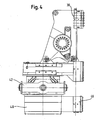
- the transmission 40 is arranged on a second carriage 46, which is guided on the mast 20.
- the second carriage 46 is guided along the same guide device 26 as the first carriage 30.
- Fig. 5 shows the arrangement Fig. 4 in addition to a second universal joint 44, which is provided below the transmission 40.
Landscapes
- Engineering & Computer Science (AREA)
- Life Sciences & Earth Sciences (AREA)
- Geology (AREA)
- Mining & Mineral Resources (AREA)
- Physics & Mathematics (AREA)
- Environmental & Geological Engineering (AREA)
- Fluid Mechanics (AREA)
- General Life Sciences & Earth Sciences (AREA)
- Geochemistry & Mineralogy (AREA)
- Mechanical Engineering (AREA)
- Earth Drilling (AREA)
- Perforating, Stamping-Out Or Severing By Means Other Than Cutting (AREA)
Description
- Die Erfindung betrifft ein Bohrgerät mit einem Mast, einem am Mast geführten Bohrantrieb zum Antreiben eines Bohrgestänges und einem Getriebe, welches zwischen Bohrantrieb und Bohrgestänge zur Übersetzung angeordnet ist.
- Häufig sollen mit einem derartigen Bohrgerät unterschiedliche Bohrverfahren ausgeführt werden oder es sind während eines komplexen Bohrverfahrens unterschiedliche Anforderungen an Drehgeschwindigkeit und/oder Drehmoment des Bohrers beziehungsweise Bohrgestänges gestellt.
- Eine Möglichkeit, diesen unterschiedlichen Anforderungen gerecht zu werden, besteht darin, unterschiedliche Bohrgeräte zu verwenden. Dies bedeutet bei einem komplexen Bohrverfahren jedoch einen erheblichen Aufwand, da zum Beispiel aufeinander folgende Bohrschritte mit unterschiedlichen Bohrgeräten ausgeführt werden müssen.
- Bei bekannten Bohrgeräten ist daher zum Beispiel vorgesehen, dass die Drehgeschwindigkeit eines Bohrantriebs regel- oder steuerbar ist. Somit lassen sich auch mit einem einzigen Bohrgerät unterschiedliche Drehgeschwindigkeiten und Drehmomente an Bohrgestänge beziehungsweise Bohrer realisieren. Nachteilig hieran sind jedoch der relativ hohe Konstruktionsaufwand für den Motor und die komplexe Steuerung. Ein solches Bohrgerät ist daher mit vergleichsweise hohen Herstellungskosten und hohen Wartungskosten verbunden. Ein Bohrgerät mit einem regelbaren Bohrantrieb ist in
JP 8-226372 JP 07-076984 DE 197 21 059 offenbart ein Bohrgerät gemäß Oberbegriff der Ansprüche 1 und 10. - Alternativ wurden Bohrgeräte mit schaltbaren Getrieben vorgeschlagen. Diese Getriebe sind im Allgemeinen relativ komplex aufgebaut. Ein Bohrgerät mit einer anpassbaren Übersetzung zwischen Bohrantrieb und Bohrgestänge ist beispielsweise aus der
JP 2002-97882 - Die bekannten Bohrgeräte, die eine Anpassung der Drehgeschwindigkeit des Bohrgestänges zulassen, haben entweder einen komplexen Antrieb oder ein komplexes Getriebe.
- Der Erfindung liegt vor diesem Hintergrund die Aufgabe zugrunde, ein Bohrgerät und ein Bohrverfahren anzugeben, die bei möglichst einfachem und wartungsarmem Aufbau des Bohrgeräts eine einfache Anpassung der Drehgeschwindigkeit eines Bohrgestänges ermöglichen.
- Die Aufgabe wird erfindungsgemäß dadurch gelöst, dass das Getriebe zur Invertierung der Übersetzung lösbar und wendbar an dem Bohrantrieb angeordnet ist.
- Zur Anpassung der Drehgeschwindigkeit des Bohrgestänges und damit des mit diesem verbundenen Bohrers wird das Getriebe vom Bohrantrieb gelöst, gewendet und in gewendetem Zustand wieder mit dem Bohrantrieb verbunden.
- Ein in einem ersten Zustand mit dem Bohrantrieb verbundener Getriebeeingang wird also in einem zweiten, gewendeten Zustand zur Verbindung mit dem Bohrgestänge verwendet. Gleichzeitig wird ein im ersten Zustand zur Verbindung mit dem Bohrgestänge vorgesehener Getriebeausgang im zweiten, gewendeten Zustand mit dem Bohrantrieb verbunden.
- Getriebeeingang und Getriebeausgang sind zu diesem Zweck derart gestaltet, dass sie jeweils sowohl mit dem Bohrantrieb als auch mit dem Bohrgestänge verbindbar sind.
- Das erfindungsgemäße Bohrgerät kann somit in besonders einfacher Weise zwei unterschiedliche Übersetzungen und damit Drehgeschwindigkeiten des Bohrgestänges bereitstellen.
- Das Getriebe kann dabei relativ einfach aufgebaut sein. Insbesondere kann das Getriebe ein nicht schaltbares Getriebe sein, welches im Grundsatz aus Bohrgeräten bekannt ist. Auch ist kein dem Bohrverfahren angepasster Bohrantrieb und keine Umgestaltung einer hydraulischen Schaltung notwendig. Der Bohrantrieb kann ein nur eine Drehgeschwindigkeit liefernder Motor sein, das heißt er braucht hinsichtlich Drehgeschwindigkeit nicht steuerbar beziehungsweise nicht regelbar zu sein.
- Eine besonders bevorzugte Ausführungsform des erfindungsgemäßen Bohrgeräts ist dadurch gekennzeichnet, dass das Getriebe eine Antriebseinheit mit einer ersten Verbindungseinrichtung zum Verbinden mit dem Bohrantrieb und eine Abtriebseinheit mit einer zweiten Verbindungseinrichtung zum Verbinden mit dem Bohrgestänge aufweist und dass die erste Verbindungseinrichtung und die zweite Verbindungseinrichtung im Wesentlichen gleich ausgebildet sind.
- Die Antriebseinheit kann insbesondere eine Welle darstellen, welche an einem Getriebeeingang angeordnet ist und als Antriebswelle bezeichnet werden kann. Zum Verbinden mit dem Bohrantrieb, insbesondere einer Ausgangswelle des Bohrantriebs, welche auch als Motorausgangswelle bezeichnet werden kann, ist an der Antriebseinheit eine erste Verbindungseinrichtung vorgesehen. Diese Verbindungseinrichtung kann mit dem Bohrantrieb beziehungsweise der Motorausgangswelle und mit dem Getriebe kraft-, form- und/oder materialschlüssig verbindbar sein. Besonders bevorzugt ist es, dass die Verbindung zwischen Bohrantrieb und Getriebe über Formschluss, beispielsweise über eine Zahnverbindung oder über eine Feder-Nut-Verbindung herstellbar ist.
- An einem Getriebeausgang weist das Getriebe eine Abtriebseinheit auf, welche ebenfalls als Welle ausgebildet sein kann und als Abtriebswelle bezeichnet werden kann. Über eine zweite Verbindungseinrichtung ist die Abtriebseinheit mit dem Bohrgestänge verbindbar.
- Grundsätzlich ist es möglich, dass erste und zweite Verbindungseinrichtung unterschiedlich ausgebildet sind und beispielsweise nach Wendung des Getriebes zur Verbindung mit Bohrantrieb beziehungsweise Bohrgestänge ausgetauscht oder mit jeweils angepassten Adaptern versehen werden. Besonders bevorzugt ist es hingegen, dass die erste Verbindungseinrichtung und die zweite Verbindungseinrichtung im Wesentlichen gleich ausgebildet sind. Hierdurch lässt sich das Getriebe in besonders einfacher Weise in gewendetem Zustand erneut mit dem Bohrantrieb und dem Bohrgestänge verbinden. Dabei wird die Abtriebseinheit mit dem Bohrantrieb und die Antriebseinheit mit dem Bohrgestänge verbunden.
- Eine erfindungsgemäße Ausgestaltung ist dadurch gegeben, dass das Getriebe ringförmig ausgebildet ist. Hierunter ist insbesondere zu verstehen, dass sowohl Antriebseinheit als auch Abtriebseinheit als zumindest teilweise hohlförmige Wellen ausgebildet sind. Das ringförmige Getriebe bietet den Vorteil, dass die Motorausgangswelle und das Bohrgestänge besonders einfach mit dem Getriebe verbindbar sind, indem diese in die jeweils hohlförmigen Wellen eingebracht werden. Mittels geeigneter Verbindungseinrichtungen, insbesondere lösbaren Kupplungen, wie sie grundsätzlich aus dem Stand der Technik bekannt sind, werden die so ineinander gesteckten Wellen drehfest miteinander verbunden.
- Eine bevorzugte Ausführungsform der Erfindung besteht darin, dass das Getriebe an dem Bohrantrieb anflanschbar ist. Durch die Flanschverbindung wird erreicht, dass das Getriebe ohne großen Aufwand vom Bohrantrieb gelöst werden kann. Um das Getriebe in gewendetem Zustand ebenfalls an dem Bohrantrieb anflanschen zu können, ist es besonders bevorzugt, dass am Getriebeeingang und am Getriebeausgang im Wesentlichen gleiche Flansche vorgesehen sind. Der jeweils auf Seite des Bohrgestänges liegende Flansch kann dabei in eingebautem Zustand des Getriebes ohne Funktion sein.
- Zum Ausgleichen eines Winkelversatzes zwischen Bohrantrieb und Getriebe ist es besonders bevorzugt, dass das Getriebe über ein Kardangelenk mit dem Bohrantrieb verbindbar ist. Durch das zwischen Bohrantrieb und Getriebe angeordnete Kardangelenk kann ein Winkel zwischen den Längsachsen der Motorausgangswelle und der Antriebseinheit, insbesondere Antriebswelle, überbrückt werden.
- Gemäß einer bevorzugten Weiterbildung der Erfindung ist vorgesehen, dass der Bohrantrieb an einem am Mast geführten ersten Schlitten angeordnet ist. Zum axialen Vorschub des Bohrers und des Bohrgestänges werden Bohrantrieb und Getriebe axial am Mast verfahren, so dass ein teleskopierbares Gestänge zum Axialvorschub grundsätzlich nicht erforderlich ist.
- In einer besonders bevorzugten Ausführungsform der Erfindung ist vorgesehen, dass das Getriebe an einem am Mast geführten zweiten Schlitten angeordnet ist. Diese Anordnung ermöglicht ein besonders komfortables Wenden des Getriebes. Hierzu wird folgendes Vorgehen vorgeschlagen. Zunächst wird die Verbindung zwischen Bohrantrieb und Getriebe gelöst und das Bohrgestänge vom Getriebe abgenommen. Anschließend wird der zweite Schlitten axial am Mast festgelegt und der erste Schlitten mit dem Bohrantrieb axial vom zweiten Schlitten weg verfahren. Sodann wird das Getriebe gewendet. Schließlich wird der erste Schlitten mit dem Bohrantrieb zum Verbinden mit dem Getriebe in gewendetem Zustand wieder axial in Richtung des Getriebes verfahren.
- Besonders vorteilhaft ist es dabei, wenn das Getriebe drehbar an dem zweiten Schlitten angeordnet ist, um ein einfaches Wenden des Getriebes, ohne dieses vom zweiten Schlitten zu lösen, zu ermöglichen. Das Eigengewicht des Getriebes kann somit auch während des Wendens vom zweiten Schlitten getragen werden und ermöglicht es einem Bediener, ohne großen Kraftaufwand eine Übersetzungsanpassung vorzunehmen. Vorteilhaft ist es in diesem Zusammenhang weiterhin, dass der zweite Schlitten eine Bremse zum axialen Feststellen am Mast aufweist.
- Eine erfindungsgemäße Weiterentwicklung ist, dass mindestens ein Kardangelenk zwischen Getriebe und Bohrgestänge vorgesehen ist. Das Kardangelenk ist insbesondere dann vorteilhaft, wenn das Bohrgestänge über eine eigene Gestängeführung am Mast geführt ist. Mittels des Kardangelenkes kann ein Winkelversatz zwischen den Längsachsen der Abtriebseinheit des Getriebes und dem Bohrgestänge ausgeglichen werden.
- Besonders bevorzugt ist der Bohrantrieb an einem ersten Schlitten, das Getriebe an einem zweiten Schlitten und das Bohrgestänge an einer Gestängeführung am Mast geführt. Durch die beiden Schlitten und die Gestängeführung ist das oben beschriebene Verfahren zum Wenden des Getriebes besonders einfach durchführbar. Sowohl Bohrantrieb als auch Bohrgestänge können am Mast gehalten werden, während das Getriebe gewendet wird. Vorteilhafterweise sind bei dieser Ausführungsform zwei Kardangelenke vorgesehen, welche zwischen Bohrantrieb und Getriebe beziehungsweise zwischen Getriebe und Bohrgestänge angeordnet sind.
- Nach der Erfindung ist es vorteilhaft, dass das Getriebe ein Getriebegehäuse mit zwei im Wesentlichen gleich ausgebildeten Flanschanschlüssen aufweist. Hierdurch ist das Getriebe in einem Ausgangszustand und in einem gewendeten Zustand ohne einen Adapter mit dem Bohrantrieb verbindbar.
- Das erfindungsgemäße Verfahren zum Betrieb des Bohrgeräts ist dadurch gekennzeichnet, dass das Getriebe zur Invertierung der Übersetzung von dem Bohrantrieb gelöst, gewendet und in dem gewendeten Zustand wieder an den Bohrantrieb angeschlossen wird. Mit diesem Verfahren kann eine Änderung der Übersetzung, beispielsweise zur Anpassung an ein anderes Bohrverfahren, besonders zeitsparend und kostengünstig durchgeführt werden. Ein aufwändiges Umrüsten des Bohrgeräts oder gar ein Ersetzen des Bohrgeräts durch ein anderes Bohrgerät kann vermieden werden.
- Die Erfindung wird im Folgenden anhand beiliegender Figuren beispielhaft weiter erläutert. Es zeigt:
- Fig. 1
- ein Bohrgerät mit einem Bohrantrieb und einem Getriebe mit einer Übersetzung ins Schnelle;
- Fig. 2
- eine Ausführungsform eines Bohrantriebs mit direkt angeflanschtem Getriebe zur Drehmomenterhöhung;
- Fig. 3
- das in
Fig. 2 dargestellte Getriebe, zusätzlich mit Kardangelenk am Getriebeausgang; - Fig. 4
- eine Ausführungsform eines Bohrantriebs mit Getriebe mit Übersetzung ins Schnelle und Kardangelenk am Getriebeeingang; und
- Fig. 5
- das in
Fig. 4 dargestellte Getriebe, zusätzlich mit Kardangelenk am Getriebeausgang. - In
Fig. 1 ist ein erfindungsgemäßes Bohrgerät 1 mit einem Mast 20, einem Bohrantrieb 22 und einem Getriebe 40 dargestellt. Das Bohrgerät 1 weist ein Fahrwerk 10 auf, welches aus einem Unterwagen 12 und einem daran drehbar angelenkten Oberwagen 14 besteht. An dem Oberwagen 14 ist der Mast 20 schwenkbar angeordnet. Mittels eines Schwenkzylinders 18 kann der Mast 20 aus einer im Wesentlichen vertikalen Betriebsposition in eine im Wesentlichen horizontale Transportposition verschwenkt werden. In einem hinteren Bereich des Oberwagens 14 ist eine Winde 15 angeordnet, welche ein Seil 17, das zu einer im oberen Bereich des Mastes angeordneten Umlenkrolle führt, aufnimmt. Der Mast 20 weist ferner einen Mastkopf 24 auf. In seiner Betriebsposition ist der Mast 20 vor einem vorderen Bereich des Fahrwerks 10 angeordnet. An einer Mastvorderseite, das heißt einer dem Fahrwerk 10 abgewandten Seite, weist der Mast 20 eine Führungseinrichtung 26 auf, an welcher ein erster Schlitten 30 entlang des Mastes 20 führbar ist. Die Führungseinrichtung 26 weist zwei Führungsschienen auf, die seitlich in einem vorderen Bereich des Mastes angeordnet sind. Der erste Schlitten 30 weist vier Führungsbacken 32 auf, wobei jeweils zwei Führungsbacken 32 mit einer Führungsschiene gleitend in Eingriff stehen. An dem ersten Schlitten 30 ist ein Vorschubantrieb 34 angeordnet, welcher zum Verschieben des ersten Schlittens 30 entlang des Mastes 20 vorgesehen ist. Hierzu sind am Mast 20 zwei feststehende Ketten 38 angeordnet. Der Vorschubantrieb 34 ist mit zwei Antriebsritzeln drehfest verbunden, welche mit den feststehenden Ketten 38 derart verbunden sind, dass bei Betrieb des Vorschubantriebs 34 der Vorschubantrieb 34 zusammen mit dem ersten Schlitten 30 entlang der feststehenden Ketten 38 bewegt wird. - Der erste Schlitten 30 weist ferner einen Bohrantrieb 22 auf, welcher zum drehenden Antreiben eines Bohrgestänges vorgesehen ist. Der Bohrantrieb 22 kann somit auch als Drehantrieb bezeichnet werden. Bei dem Bohrgestänge kann es sich beispielsweise um eine Kellystange oder aber auch um ein Bohrrohr handeln, welches zur Abstützung des Bohrloches beim so genannten Kellybohren verwendet wird. Unterhalb des Bohrantriebs 22 ist über ein erstes Kardangelenk 42 ein Getriebe 40 angeflanscht, welches die Drehzahl anhebt und das Drehmoment senkt. In dieser Ausführungsform ist das Bohrgerät 1 beispielsweise für Verdrängerbohrungen oder CSV-Bohrungen geeignet, welche eine hohe Drehzahl benötigen.
- Das Getriebe 40 ist an einem eigenen, zweiten Schlitten 46, welcher ebenfalls entlang des Mastes 20 führbar ist, angeordnet. Unterhalb des Getriebes 40 ist ein zweites Kardangelenk 44 angeflanscht, welches zur Aufnahme des Bohrgestänges vorgesehen ist.
- Erfindungsgemäß ist das Getriebe 40 zur Invertierung der Übersetzung lösbar und wendbar an dem Bohrantrieb 22 angeordnet. Zur Führung und/oder zum Festhalten des Bohrgestänges ist unterhalb des Getriebes 40 und des zweiten Kardangelenks 44 eine Gestängeführung 50 vorgesehen. Diese ist an dem Mast 20 befestigt.
- In
Fig. 2 ist eine Ausführungsform eines erfindungsgemäßen Getriebes 40 dargestellt. Das Getriebe 40 ist in der gezeigten Darstellung derart angeordnet, dass es eine Übersetzung ins Langsame und somit eine Drehmomenterhöhung bewirkt. Ein hohes Drehmoment wird beispielsweise für das sogenannte Kellybohren benötigt. Das Getriebe 40 ist direkt, ohne Kardangelenk, an dem Bohrantrieb 22 angeschlossen. Hierzu ist ein Getriebegehäuse, welches das Getriebe 40 aufnimmt, an den ersten Schlitten 30 angeflanscht. Bohrantrieb 22 und Getriebe 40 stehen drehbar miteinander in Eingriff. Hierzu ist eine Motorausgangswelle des Bohrantriebs 22 über eine Kupplung mit einer Antriebseinheit des Getriebes 40, welche als Hohlwelle ausgebildet ist, verbunden. An dem dem Bohrantrieb 22 gegenüberliegenden Ende des Getriebes 40 kann ein Bohrgestänge derart mit dem Getriebe 40 verbunden werden, dass ein Drehmoment auf dieses übertragen wird. -
Fig. 3 zeigt das inFig. 2 dargestellte Getriebe 40 mit Bohrantrieb 22, zusätzlich mit einem zweiten Kardangelenk 44, welches unterhalb des Getriebes 40 angeordnet ist. Das zweite Kardangelenk 44 ist zur Aufnahme eines Bohrgestänges vorgesehen. - In
Fig. 4 ist ein Getriebe 40 mit einer Übersetzung ins Schnelle vorgesehen, das heißt, das Getriebe 40 bewirkt eine Drehzahlerhöhung und eine Drehmomenterniedrigung. Zwischen Getriebe 40 und Bohrantrieb 22 ist ein erstes Kardangelenk 42 angeordnet. Das Getriebe 40 ist an einem zweiten Schlitten 46 angeordnet, welcher am Mast 20 geführt ist. Der zweite Schlitten 46 ist entlang derselben Führungseinrichtung 26 wie der erste Schlitten 30 geführt. -
Fig. 5 zeigt die Anordnung ausFig. 4 , zusätzlich mit einem zweiten Kardangelenk 44, welches unterhalb des Getriebes 40 vorgesehen ist.
Claims (10)
- Bohrgerät mit- einem Mast (20),- einem am Mast (20) geführten Bohrantrieb (22) zum Antreiben eines Bohrgestänges und- einem Getriebe (40), welches zwischen Bohrantrieb (22) und Bohrgestänge zur Übersetzung angeordnet ist,dadurch gekennzeichnet,
dass das Getriebe (40) zur Invertierung der Übersetzung lösbar und wendbar an dem Bohrantrieb (22) angeordnet ist. - Bohrgerät nach Anspruch 1,
dadurch gekennzeichnet,
dass das Getriebe (40) eine Antriebseinheit mit einer ersten Verbindungseinrichtung zum Verbinden mit dem Bohrantrieb und eine Abtriebseinheit mit einer zweiten Verbindungseinrichtung zum Verbinden mit dem Bohrgestänge aufweist und dass die erste Verbindungseinrichtung zum Verbinden mit dem Bohrgestänge und die zweite Verbindungseinrichtung im Wesentlichen gleich ausgebildet sind. - Bohrgerät nach Anspruch 1 oder 2,
dadurch gekennzeichnet,
dass das Getriebe (40) ringförmig ausgebildet ist. - Bohrgerät nach einem der Ansprüche 1 bis 3,
dadurch gekennzeichnet,
dass das Getriebe (40) an dem Bohrantrieb (22) anflanschbar ist. - Bohrgerät nach einem der Ansprüche 1 bis 3,
dadurch gekennzeichnet,
dass das Getriebe (40) über ein Kardangelenk (42) mit dem Bohrantrieb (22) verbindbar ist. - Bohrgerät nach einem der Ansprüche 1 bis 5,
dadurch gekennzeichnet,
dass der Bohrantrieb (22) an einem am Mast (20) geführten ersten Schlitten (30) angeordnet ist. - Bohrgerät nach einem der Ansprüche 1 bis 6,
dadurch gekennzeichnet,
dass das Getriebe (40) an einem am Mast (20) geführten zweiten Schlitten (46) angeordnet ist. - Bohrgerät nach einem der Ansprüche 1 bis 7,
dadurch gekennzeichnet,
dass mindestens ein Kardangelenk (44) zwischen Getriebe (40) und Bohrgestänge vorgesehen ist. - Bohrgerät nach einem der Ansprüche 1 bis 8,
dadurch gekennzeichnet,
dass das Getriebe (40) ein Getriebegehäuse mit zwei im Wesentlichen gleich ausgebildeten Flanschanschlüssen aufweist. - Verfahren zum Betrieb eines Bohrgeräts (1) mit einem Mast (20), einem am Mast (20) geführten Bohrantrieb (22) zum Antreiben eines Bohrgestänges und einem Getriebe (40), welches zwischen Bohrantrieb (22) und Bohrgestänge zur Übersetzung angeordnet ist, insbesondere nach einem der Ansprüche 1 bis 9,
dadurch gekennzeichnet,
dass das Getriebe (40) zur Invertierung der Übersetzung von dem Bohrantrieb (22) gelöst, gewendet und in dem gewendeten Zustand wieder an den Bohrantrieb (22) angeschlossen wird.
Priority Applications (9)
| Application Number | Priority Date | Filing Date | Title |
|---|---|---|---|
| EP07018414A EP2048321B1 (de) | 2007-09-19 | 2007-09-19 | Bohrgerät und Verfahren zum Betreib eines Bohrgeräts |
| DE502007002826T DE502007002826D1 (de) | 2007-09-19 | 2007-09-19 | Bohrgerät und Verfahren zum Betreib eines Bohrgeräts |
| AT07018414T ATE457411T1 (de) | 2007-09-19 | 2007-09-19 | Bohrgerät und verfahren zum betreib eines bohrgeräts |
| MYPI20083341A MY144864A (en) | 2007-09-19 | 2008-08-29 | Drilling implement and method for operating a drilling implement |
| US12/230,709 US8002048B2 (en) | 2007-09-19 | 2008-09-03 | Drilling implement and method for operating a drilling implement |
| SG200806680-5A SG151201A1 (en) | 2007-09-19 | 2008-09-11 | Drilling implement and method for operating a drilling implement |
| JP2008236132A JP4864951B2 (ja) | 2007-09-19 | 2008-09-16 | 掘削装置および掘削装置の操作方法 |
| RU2008137262/03A RU2393318C2 (ru) | 2007-09-19 | 2008-09-18 | Агрегат для бурения грунта и способ его эксплуатации |
| CN2008101490905A CN101392630B (zh) | 2007-09-19 | 2008-09-19 | 钻井设备和操作钻井设备的方法 |
Applications Claiming Priority (1)
| Application Number | Priority Date | Filing Date | Title |
|---|---|---|---|
| EP07018414A EP2048321B1 (de) | 2007-09-19 | 2007-09-19 | Bohrgerät und Verfahren zum Betreib eines Bohrgeräts |
Publications (2)
| Publication Number | Publication Date |
|---|---|
| EP2048321A1 EP2048321A1 (de) | 2009-04-15 |
| EP2048321B1 true EP2048321B1 (de) | 2010-02-10 |
Family
ID=38727505
Family Applications (1)
| Application Number | Title | Priority Date | Filing Date |
|---|---|---|---|
| EP07018414A Not-in-force EP2048321B1 (de) | 2007-09-19 | 2007-09-19 | Bohrgerät und Verfahren zum Betreib eines Bohrgeräts |
Country Status (9)
| Country | Link |
|---|---|
| US (1) | US8002048B2 (de) |
| EP (1) | EP2048321B1 (de) |
| JP (1) | JP4864951B2 (de) |
| CN (1) | CN101392630B (de) |
| AT (1) | ATE457411T1 (de) |
| DE (1) | DE502007002826D1 (de) |
| MY (1) | MY144864A (de) |
| RU (1) | RU2393318C2 (de) |
| SG (1) | SG151201A1 (de) |
Cited By (1)
| Publication number | Priority date | Publication date | Assignee | Title |
|---|---|---|---|---|
| EP3372777A1 (de) | 2017-03-06 | 2018-09-12 | Soilmec S.p.A. | Modularer zusammenbau zur behandlung von ausbaugeräten für aushebmaschinen, aushebmaschine, verfahren zur konvertierung der ausgestatteten konfiguration einer ausbaggermaschine |
Families Citing this family (11)
| Publication number | Priority date | Publication date | Assignee | Title |
|---|---|---|---|---|
| EP2378001B1 (de) * | 2010-04-16 | 2013-06-12 | BAUER Maschinen GmbH | Bodenbearbeitungsvorrichtung |
| PL3214258T3 (pl) * | 2011-06-09 | 2018-07-31 | Bauer Maschinen Gmbh | Robocze urządzenie budowlane i sposób ustawiania masztu urządzenia budowlanego |
| JP5730145B2 (ja) * | 2011-06-30 | 2015-06-03 | 日本車輌製造株式会社 | 杭打機用変速装置 |
| US9016402B2 (en) * | 2011-09-08 | 2015-04-28 | Garry Thorne | Geological drill |
| WO2013103610A1 (en) * | 2012-01-04 | 2013-07-11 | Longyear Tm, Inc. | Over center drill head gear shifting system |
| WO2013106207A1 (en) * | 2012-01-11 | 2013-07-18 | Longyear Tm, Inc. | Progressive dual-shift drill head and systems and methods thereof |
| CN104074467B (zh) * | 2014-06-25 | 2016-03-30 | 上海中联重科桩工机械有限公司 | 桅杆与动力头的连接机构和组合及具有该组合的旋挖钻机 |
| PL3228756T5 (pl) * | 2016-04-04 | 2023-07-03 | Bauer Maschinen Gmbh | Maszyna robocza i sposób obrabiania gruntu |
| US10563770B2 (en) * | 2016-05-05 | 2020-02-18 | National Oilwell Varco, L.P. | Washpipe assemblies for a power swivel |
| CN106245624B (zh) * | 2016-09-30 | 2018-12-11 | 上海金泰工程机械有限公司 | 自升式钢筋笼插筋辅助装置及其使用方法 |
| CN114151010B (zh) * | 2021-12-14 | 2023-12-08 | 刘继芳 | 一种矿产地质勘查装置 |
Family Cites Families (28)
| Publication number | Priority date | Publication date | Assignee | Title |
|---|---|---|---|---|
| US3766991A (en) * | 1971-04-02 | 1973-10-23 | Brown Oil Tools | Electric power swivel and system for use in rotary well drilling |
| US3730285A (en) * | 1971-10-08 | 1973-05-01 | Gardner Denver Co | Rock drill bit guide and mast stabilizer |
| JPS5441507A (en) * | 1977-09-09 | 1979-04-02 | Sanwa Kizai Co Ltd | Variable speed drive device of earth auger |
| US4232752A (en) * | 1978-03-20 | 1980-11-11 | Service Equipment Design Co., Inc. | Method and apparatus for driving pipe |
| US4258796A (en) * | 1978-07-31 | 1981-03-31 | The Salem Tool Company | Earth drilling apparatus |
| JPS57123890A (en) * | 1981-01-23 | 1982-08-02 | Hitachi Ltd | Furnace for pulling up single crystal |
| JPS63176585A (ja) * | 1987-01-19 | 1988-07-20 | 横山 弘介 | ハンマ−掘削機 |
| JPS6457190A (en) * | 1987-08-28 | 1989-03-03 | Hochiki Co | Electronic count apparatus |
| RU2026488C1 (ru) * | 1987-10-30 | 1995-01-09 | Московский государственный горный университет | Буровой станок |
| US4877091A (en) * | 1988-06-27 | 1989-10-31 | Howell Jr Richard L | Augering apparatus and drilling rig |
| US4984641A (en) * | 1990-02-07 | 1991-01-15 | Pryor Dale H | Swivels |
| US5281775A (en) * | 1992-10-16 | 1994-01-25 | Richard A. Gremillion | Vibrating hole forming device for seismic exploration |
| JP3443705B2 (ja) | 1993-09-08 | 2003-09-08 | 中央自動車興業株式会社 | アースオーガの3速式出力装置 |
| JPH08226372A (ja) | 1995-02-21 | 1996-09-03 | Shirota:Kk | 回転駆動装置 |
| DE19509379A1 (de) * | 1995-03-15 | 1996-09-19 | Fromme Theo Dipl Ing Fh | Hydraulische Verrohrungsmaschine als Anbaugerät für eine mobile Drehbohranlage |
| DE19721059C1 (de) * | 1997-05-20 | 1998-11-12 | Klemm Ingrid | Erdbohrgerät |
| GB0001323D0 (en) * | 2000-01-20 | 2000-03-08 | Sol Comp Du | Rotary displacement piling equipment |
| CN2430473Y (zh) * | 2000-01-31 | 2001-05-16 | 北京市机械施工公司 | 多功能桩架 |
| US6412554B1 (en) * | 2000-03-14 | 2002-07-02 | Weatherford/Lamb, Inc. | Wellbore circulation system |
| JP4612937B2 (ja) * | 2000-07-04 | 2011-01-12 | 日本車輌製造株式会社 | オーガ回転駆動装置用変速装置 |
| JP2002081285A (ja) * | 2000-09-11 | 2002-03-22 | Nippon Sharyo Seizo Kaisha Ltd | 2軸同軸デバイス |
| JP4448608B2 (ja) | 2000-09-22 | 2010-04-14 | 日本車輌製造株式会社 | 施工具用回転駆動装置 |
| DE60219033T2 (de) * | 2001-08-27 | 2007-12-13 | Varco I/P, Inc., Houston | Spülrohranordnung |
| US7093679B1 (en) * | 2003-06-05 | 2006-08-22 | Watson Incorporated | Foundation drilling apparatus and method with continuously variable hydraulic differential rotary table |
| DE10360912B3 (de) * | 2003-12-23 | 2005-05-12 | Bauer Maschinen Gmbh | Bohrgerät und Verfahren zum Einbringen eines Bohrelements in den Boden |
| US7188686B2 (en) * | 2004-06-07 | 2007-03-13 | Varco I/P, Inc. | Top drive systems |
| ES2282782T3 (es) * | 2004-11-08 | 2007-10-16 | Bauer Maschinen Gmbh | Dispositivo para la construccion. |
| DE102006022613B4 (de) * | 2006-05-15 | 2008-08-07 | Klemm Bohrtechnik Zweigniederlassung Der Bauer Maschinen Gmbh | Bohrantriebseinheit und Bohrgerät |
-
2007
- 2007-09-19 EP EP07018414A patent/EP2048321B1/de not_active Not-in-force
- 2007-09-19 AT AT07018414T patent/ATE457411T1/de active
- 2007-09-19 DE DE502007002826T patent/DE502007002826D1/de active Active
-
2008
- 2008-08-29 MY MYPI20083341A patent/MY144864A/en unknown
- 2008-09-03 US US12/230,709 patent/US8002048B2/en not_active Expired - Fee Related
- 2008-09-11 SG SG200806680-5A patent/SG151201A1/en unknown
- 2008-09-16 JP JP2008236132A patent/JP4864951B2/ja not_active Expired - Fee Related
- 2008-09-18 RU RU2008137262/03A patent/RU2393318C2/ru not_active IP Right Cessation
- 2008-09-19 CN CN2008101490905A patent/CN101392630B/zh not_active Expired - Fee Related
Cited By (1)
| Publication number | Priority date | Publication date | Assignee | Title |
|---|---|---|---|---|
| EP3372777A1 (de) | 2017-03-06 | 2018-09-12 | Soilmec S.p.A. | Modularer zusammenbau zur behandlung von ausbaugeräten für aushebmaschinen, aushebmaschine, verfahren zur konvertierung der ausgestatteten konfiguration einer ausbaggermaschine |
Also Published As
| Publication number | Publication date |
|---|---|
| US20090071674A1 (en) | 2009-03-19 |
| ATE457411T1 (de) | 2010-02-15 |
| CN101392630B (zh) | 2012-03-21 |
| SG151201A1 (en) | 2009-04-30 |
| DE502007002826D1 (de) | 2010-03-25 |
| CN101392630A (zh) | 2009-03-25 |
| MY144864A (en) | 2011-11-30 |
| JP2009074360A (ja) | 2009-04-09 |
| US8002048B2 (en) | 2011-08-23 |
| RU2008137262A (ru) | 2010-03-27 |
| RU2393318C2 (ru) | 2010-06-27 |
| EP2048321A1 (de) | 2009-04-15 |
| JP4864951B2 (ja) | 2012-02-01 |
Similar Documents
| Publication | Publication Date | Title |
|---|---|---|
| EP2048321B1 (de) | Bohrgerät und Verfahren zum Betreib eines Bohrgeräts | |
| DE4103160C2 (de) | Falzapparat mit einem verstellbare Elemente, insbesondere Falzklappen oder bogenförmige Segmente, aufweisenden Falzwerkzylinder | |
| DE1257077B (de) | Selbstfortschreitende Vorbohrmaschine | |
| DE2656209C3 (de) | Gesteinsbohrgerät | |
| EP3524771B1 (de) | Bohrvorrichtung zum erd- oder gesteinsbohren sowie verfahren zum nachrüsten einer solchen bohrvorrichtung | |
| EP1580327B1 (de) | Schlitzwandfräse | |
| DE3313542C1 (de) | Antriebsvorrichtung fuer Giesswalzen | |
| EP3877624A1 (de) | Kellystangenanordnung für ein bohrgerät und verfahren zur bodenbearbeitung | |
| DE3839007C1 (de) | ||
| WO1996028630A1 (de) | Hydraulische verrohrungsmaschine als anbaugerät für eine mobile drehbohranlage | |
| EP1124037A1 (de) | Bohrvorrichtung | |
| EP0149056B1 (de) | Verfahrbare Bohreinrichtung | |
| DE1935428C3 (de) | Schneckengetriebe zum Antrieb von Schlitten an Werkzeugmaschinen, insbesondere an Fräsmaschinen | |
| EP3221083B1 (de) | Bearbeitungseinheit für eine werkzeugmaschine und werkzeugmaschine mit einer derartigen bearbeitungseinheit | |
| DE2156153A1 (de) | Spindelanordnung fuer werkzeugmaschinen | |
| DE19745497C2 (de) | Vorrichtung zum Beobachten und/oder Bearbeiten der Innenwände von Rohren | |
| DE2520542C3 (de) | ||
| EP2626506B1 (de) | Vorrichtung zum Bewegen eines Arbeitsmittels im Erdreich | |
| DE4311365A1 (de) | Vorrichtung zum Innenbearbeiten von Rohren, Kanälen oder dergleichen | |
| EP3456914A1 (de) | Doppelkopf-bohrvorrichtung und verfahren zum erstellen einer bohrung | |
| DE3128228A1 (de) | Hohlwellenantrieb | |
| EP4033067B1 (de) | Drehantriebsanordnung für ein bohrgestänge | |
| EP4310293B1 (de) | Bohranordnung | |
| EP4036367B1 (de) | Anordnung einer erdbohrvorrichtung, verfahren zum betrieb einer erdbohrvorrichtung und verwendung einer anordnung einer erdbohrvorrichtung | |
| DE3840569A1 (de) | Vorrichtung zum ausschneiden von in eine rohrwand eingesetzten stopfen |
Legal Events
| Date | Code | Title | Description |
|---|---|---|---|
| PUAI | Public reference made under article 153(3) epc to a published international application that has entered the european phase |
Free format text: ORIGINAL CODE: 0009012 |
|
| 17P | Request for examination filed |
Effective date: 20080312 |
|
| AK | Designated contracting states |
Kind code of ref document: A1 Designated state(s): AT BE BG CH CY CZ DE DK EE ES FI FR GB GR HU IE IS IT LI LT LU LV MC MT NL PL PT RO SE SI SK TR |
|
| AX | Request for extension of the european patent |
Extension state: AL BA HR MK RS |
|
| GRAP | Despatch of communication of intention to grant a patent |
Free format text: ORIGINAL CODE: EPIDOSNIGR1 |
|
| GRAS | Grant fee paid |
Free format text: ORIGINAL CODE: EPIDOSNIGR3 |
|
| AKX | Designation fees paid |
Designated state(s): AT BE BG CH CY CZ DE DK EE ES FI FR GB GR HU IE IS IT LI LT LU LV MC MT NL PL PT RO SE SI SK TR |
|
| GRAA | (expected) grant |
Free format text: ORIGINAL CODE: 0009210 |
|
| AK | Designated contracting states |
Kind code of ref document: B1 Designated state(s): AT BE BG CH CY CZ DE DK EE ES FI FR GB GR HU IE IS IT LI LT LU LV MC MT NL PL PT RO SE SI SK TR |
|
| REG | Reference to a national code |
Ref country code: GB Ref legal event code: FG4D Free format text: NOT ENGLISH |
|
| REG | Reference to a national code |
Ref country code: CH Ref legal event code: EP |
|
| REG | Reference to a national code |
Ref country code: IE Ref legal event code: FG4D |
|
| REF | Corresponds to: |
Ref document number: 502007002826 Country of ref document: DE Date of ref document: 20100325 Kind code of ref document: P |
|
| REG | Reference to a national code |
Ref country code: NL Ref legal event code: VDEP Effective date: 20100210 |
|
| LTIE | Lt: invalidation of european patent or patent extension |
Effective date: 20100210 |
|
| PG25 | Lapsed in a contracting state [announced via postgrant information from national office to epo] |
Ref country code: LT Free format text: LAPSE BECAUSE OF FAILURE TO SUBMIT A TRANSLATION OF THE DESCRIPTION OR TO PAY THE FEE WITHIN THE PRESCRIBED TIME-LIMIT Effective date: 20100210 Ref country code: PT Free format text: LAPSE BECAUSE OF FAILURE TO SUBMIT A TRANSLATION OF THE DESCRIPTION OR TO PAY THE FEE WITHIN THE PRESCRIBED TIME-LIMIT Effective date: 20100611 Ref country code: ES Free format text: LAPSE BECAUSE OF FAILURE TO SUBMIT A TRANSLATION OF THE DESCRIPTION OR TO PAY THE FEE WITHIN THE PRESCRIBED TIME-LIMIT Effective date: 20100521 Ref country code: IS Free format text: LAPSE BECAUSE OF FAILURE TO SUBMIT A TRANSLATION OF THE DESCRIPTION OR TO PAY THE FEE WITHIN THE PRESCRIBED TIME-LIMIT Effective date: 20100610 |
|
| PG25 | Lapsed in a contracting state [announced via postgrant information from national office to epo] |
Ref country code: PL Free format text: LAPSE BECAUSE OF FAILURE TO SUBMIT A TRANSLATION OF THE DESCRIPTION OR TO PAY THE FEE WITHIN THE PRESCRIBED TIME-LIMIT Effective date: 20100210 Ref country code: SI Free format text: LAPSE BECAUSE OF FAILURE TO SUBMIT A TRANSLATION OF THE DESCRIPTION OR TO PAY THE FEE WITHIN THE PRESCRIBED TIME-LIMIT Effective date: 20100210 Ref country code: LV Free format text: LAPSE BECAUSE OF FAILURE TO SUBMIT A TRANSLATION OF THE DESCRIPTION OR TO PAY THE FEE WITHIN THE PRESCRIBED TIME-LIMIT Effective date: 20100210 Ref country code: FI Free format text: LAPSE BECAUSE OF FAILURE TO SUBMIT A TRANSLATION OF THE DESCRIPTION OR TO PAY THE FEE WITHIN THE PRESCRIBED TIME-LIMIT Effective date: 20100210 |
|
| REG | Reference to a national code |
Ref country code: IE Ref legal event code: FD4D |
|
| PG25 | Lapsed in a contracting state [announced via postgrant information from national office to epo] |
Ref country code: SE Free format text: LAPSE BECAUSE OF FAILURE TO SUBMIT A TRANSLATION OF THE DESCRIPTION OR TO PAY THE FEE WITHIN THE PRESCRIBED TIME-LIMIT Effective date: 20100210 Ref country code: EE Free format text: LAPSE BECAUSE OF FAILURE TO SUBMIT A TRANSLATION OF THE DESCRIPTION OR TO PAY THE FEE WITHIN THE PRESCRIBED TIME-LIMIT Effective date: 20100210 Ref country code: GR Free format text: LAPSE BECAUSE OF FAILURE TO SUBMIT A TRANSLATION OF THE DESCRIPTION OR TO PAY THE FEE WITHIN THE PRESCRIBED TIME-LIMIT Effective date: 20100511 Ref country code: IE Free format text: LAPSE BECAUSE OF FAILURE TO SUBMIT A TRANSLATION OF THE DESCRIPTION OR TO PAY THE FEE WITHIN THE PRESCRIBED TIME-LIMIT Effective date: 20100210 Ref country code: NL Free format text: LAPSE BECAUSE OF FAILURE TO SUBMIT A TRANSLATION OF THE DESCRIPTION OR TO PAY THE FEE WITHIN THE PRESCRIBED TIME-LIMIT Effective date: 20100210 Ref country code: RO Free format text: LAPSE BECAUSE OF FAILURE TO SUBMIT A TRANSLATION OF THE DESCRIPTION OR TO PAY THE FEE WITHIN THE PRESCRIBED TIME-LIMIT Effective date: 20100210 Ref country code: CY Free format text: LAPSE BECAUSE OF FAILURE TO SUBMIT A TRANSLATION OF THE DESCRIPTION OR TO PAY THE FEE WITHIN THE PRESCRIBED TIME-LIMIT Effective date: 20100210 |
|
| PG25 | Lapsed in a contracting state [announced via postgrant information from national office to epo] |
Ref country code: SK Free format text: LAPSE BECAUSE OF FAILURE TO SUBMIT A TRANSLATION OF THE DESCRIPTION OR TO PAY THE FEE WITHIN THE PRESCRIBED TIME-LIMIT Effective date: 20100210 Ref country code: BG Free format text: LAPSE BECAUSE OF FAILURE TO SUBMIT A TRANSLATION OF THE DESCRIPTION OR TO PAY THE FEE WITHIN THE PRESCRIBED TIME-LIMIT Effective date: 20100510 Ref country code: CZ Free format text: LAPSE BECAUSE OF FAILURE TO SUBMIT A TRANSLATION OF THE DESCRIPTION OR TO PAY THE FEE WITHIN THE PRESCRIBED TIME-LIMIT Effective date: 20100210 |
|
| PLBE | No opposition filed within time limit |
Free format text: ORIGINAL CODE: 0009261 |
|
| STAA | Information on the status of an ep patent application or granted ep patent |
Free format text: STATUS: NO OPPOSITION FILED WITHIN TIME LIMIT |
|
| 26N | No opposition filed |
Effective date: 20101111 |
|
| PG25 | Lapsed in a contracting state [announced via postgrant information from national office to epo] |
Ref country code: DK Free format text: LAPSE BECAUSE OF FAILURE TO SUBMIT A TRANSLATION OF THE DESCRIPTION OR TO PAY THE FEE WITHIN THE PRESCRIBED TIME-LIMIT Effective date: 20100210 |
|
| BERE | Be: lapsed |
Owner name: BAUER MASCHINEN G.M.B.H. Effective date: 20100930 |
|
| PG25 | Lapsed in a contracting state [announced via postgrant information from national office to epo] |
Ref country code: MC Free format text: LAPSE BECAUSE OF NON-PAYMENT OF DUE FEES Effective date: 20100930 |
|
| REG | Reference to a national code |
Ref country code: FR Ref legal event code: ST Effective date: 20110531 |
|
| PG25 | Lapsed in a contracting state [announced via postgrant information from national office to epo] |
Ref country code: BE Free format text: LAPSE BECAUSE OF NON-PAYMENT OF DUE FEES Effective date: 20100930 Ref country code: FR Free format text: LAPSE BECAUSE OF NON-PAYMENT OF DUE FEES Effective date: 20100930 |
|
| PG25 | Lapsed in a contracting state [announced via postgrant information from national office to epo] |
Ref country code: MT Free format text: LAPSE BECAUSE OF FAILURE TO SUBMIT A TRANSLATION OF THE DESCRIPTION OR TO PAY THE FEE WITHIN THE PRESCRIBED TIME-LIMIT Effective date: 20100210 |
|
| REG | Reference to a national code |
Ref country code: CH Ref legal event code: PL |
|
| GBPC | Gb: european patent ceased through non-payment of renewal fee |
Effective date: 20110919 |
|
| PG25 | Lapsed in a contracting state [announced via postgrant information from national office to epo] |
Ref country code: LI Free format text: LAPSE BECAUSE OF NON-PAYMENT OF DUE FEES Effective date: 20110930 Ref country code: CH Free format text: LAPSE BECAUSE OF NON-PAYMENT OF DUE FEES Effective date: 20110930 |
|
| PG25 | Lapsed in a contracting state [announced via postgrant information from national office to epo] |
Ref country code: GB Free format text: LAPSE BECAUSE OF NON-PAYMENT OF DUE FEES Effective date: 20110919 |
|
| PG25 | Lapsed in a contracting state [announced via postgrant information from national office to epo] |
Ref country code: LU Free format text: LAPSE BECAUSE OF NON-PAYMENT OF DUE FEES Effective date: 20100919 Ref country code: HU Free format text: LAPSE BECAUSE OF FAILURE TO SUBMIT A TRANSLATION OF THE DESCRIPTION OR TO PAY THE FEE WITHIN THE PRESCRIBED TIME-LIMIT Effective date: 20100811 |
|
| PG25 | Lapsed in a contracting state [announced via postgrant information from national office to epo] |
Ref country code: TR Free format text: LAPSE BECAUSE OF FAILURE TO SUBMIT A TRANSLATION OF THE DESCRIPTION OR TO PAY THE FEE WITHIN THE PRESCRIBED TIME-LIMIT Effective date: 20100210 |
|
| REG | Reference to a national code |
Ref country code: AT Ref legal event code: MM01 Ref document number: 457411 Country of ref document: AT Kind code of ref document: T Effective date: 20120919 |
|
| PG25 | Lapsed in a contracting state [announced via postgrant information from national office to epo] |
Ref country code: AT Free format text: LAPSE BECAUSE OF NON-PAYMENT OF DUE FEES Effective date: 20120919 |
|
| PGFP | Annual fee paid to national office [announced via postgrant information from national office to epo] |
Ref country code: IT Payment date: 20160921 Year of fee payment: 10 |
|
| PGFP | Annual fee paid to national office [announced via postgrant information from national office to epo] |
Ref country code: DE Payment date: 20160927 Year of fee payment: 10 |
|
| REG | Reference to a national code |
Ref country code: DE Ref legal event code: R119 Ref document number: 502007002826 Country of ref document: DE |
|
| PG25 | Lapsed in a contracting state [announced via postgrant information from national office to epo] |
Ref country code: DE Free format text: LAPSE BECAUSE OF NON-PAYMENT OF DUE FEES Effective date: 20180404 |
|
| PG25 | Lapsed in a contracting state [announced via postgrant information from national office to epo] |
Ref country code: IT Free format text: LAPSE BECAUSE OF NON-PAYMENT OF DUE FEES Effective date: 20170919 |