EP2048293A2 - Vorrichtung und Verfahren zur Wartung eines Kanals - Google Patents
Vorrichtung und Verfahren zur Wartung eines Kanals Download PDFInfo
- Publication number
- EP2048293A2 EP2048293A2 EP08166069A EP08166069A EP2048293A2 EP 2048293 A2 EP2048293 A2 EP 2048293A2 EP 08166069 A EP08166069 A EP 08166069A EP 08166069 A EP08166069 A EP 08166069A EP 2048293 A2 EP2048293 A2 EP 2048293A2
- Authority
- EP
- European Patent Office
- Prior art keywords
- liquid
- tank
- drain system
- drum
- filtration
- Prior art date
- Legal status (The legal status is an assumption and is not a legal conclusion. Google has not performed a legal analysis and makes no representation as to the accuracy of the status listed.)
- Withdrawn
Links
- 238000000034 method Methods 0.000 title claims abstract description 27
- 239000007788 liquid Substances 0.000 claims abstract description 96
- 238000001914 filtration Methods 0.000 claims abstract description 64
- 239000007787 solid Substances 0.000 claims abstract description 40
- XLYOFNOQVPJJNP-UHFFFAOYSA-N water Substances O XLYOFNOQVPJJNP-UHFFFAOYSA-N 0.000 claims description 63
- 238000005192 partition Methods 0.000 claims description 10
- 230000005484 gravity Effects 0.000 claims description 7
- 239000000463 material Substances 0.000 claims description 4
- 238000004140 cleaning Methods 0.000 description 25
- 238000011010 flushing procedure Methods 0.000 description 18
- 230000008569 process Effects 0.000 description 15
- 238000005406 washing Methods 0.000 description 14
- 239000010802 sludge Substances 0.000 description 13
- 238000009288 screen filtration Methods 0.000 description 9
- 239000000126 substance Substances 0.000 description 8
- 230000008014 freezing Effects 0.000 description 5
- 238000007710 freezing Methods 0.000 description 5
- 230000008901 benefit Effects 0.000 description 4
- 238000010438 heat treatment Methods 0.000 description 4
- 238000011144 upstream manufacturing Methods 0.000 description 4
- 238000010586 diagram Methods 0.000 description 3
- 230000003749 cleanliness Effects 0.000 description 2
- 230000000694 effects Effects 0.000 description 2
- 238000005189 flocculation Methods 0.000 description 2
- 230000016615 flocculation Effects 0.000 description 2
- 238000012423 maintenance Methods 0.000 description 2
- 239000000203 mixture Substances 0.000 description 2
- 238000005086 pumping Methods 0.000 description 2
- 239000004576 sand Substances 0.000 description 2
- 101100117236 Drosophila melanogaster speck gene Proteins 0.000 description 1
- 230000006978 adaptation Effects 0.000 description 1
- 230000004323 axial length Effects 0.000 description 1
- 239000004927 clay Substances 0.000 description 1
- 238000010276 construction Methods 0.000 description 1
- 238000010924 continuous production Methods 0.000 description 1
- 238000007667 floating Methods 0.000 description 1
- 239000012535 impurity Substances 0.000 description 1
- 229910052500 inorganic mineral Inorganic materials 0.000 description 1
- 230000002452 interceptive effect Effects 0.000 description 1
- 238000005259 measurement Methods 0.000 description 1
- 239000002184 metal Substances 0.000 description 1
- 239000011707 mineral Substances 0.000 description 1
- 229920000642 polymer Polymers 0.000 description 1
- 238000011045 prefiltration Methods 0.000 description 1
- 230000009467 reduction Effects 0.000 description 1
- 230000001105 regulatory effect Effects 0.000 description 1
- 230000008439 repair process Effects 0.000 description 1
- 238000000926 separation method Methods 0.000 description 1
- 238000005507 spraying Methods 0.000 description 1
- 229910001220 stainless steel Inorganic materials 0.000 description 1
- 239000010935 stainless steel Substances 0.000 description 1
Images


Classifications
-
- E—FIXED CONSTRUCTIONS
- E03—WATER SUPPLY; SEWERAGE
- E03F—SEWERS; CESSPOOLS
- E03F9/00—Arrangements or fixed installations methods or devices for cleaning or clearing sewer pipes, e.g. by flushing
-
- B—PERFORMING OPERATIONS; TRANSPORTING
- B08—CLEANING
- B08B—CLEANING IN GENERAL; PREVENTION OF FOULING IN GENERAL
- B08B9/00—Cleaning hollow articles by methods or apparatus specially adapted thereto
- B08B9/02—Cleaning pipes or tubes or systems of pipes or tubes
- B08B9/027—Cleaning the internal surfaces; Removal of blockages
-
- E—FIXED CONSTRUCTIONS
- E03—WATER SUPPLY; SEWERAGE
- E03F—SEWERS; CESSPOOLS
- E03F7/00—Other installations or implements for operating sewer systems, e.g. for preventing or indicating stoppage; Emptying cesspools
- E03F7/10—Wheeled apparatus for emptying sewers or cesspools
Definitions
- the present invention relates to an apparatus for servicing a drain system, which apparatus includes
- the invention also relates to a corresponding system.
- drain-servicing apparatuses for example fitted to vehicles, are known from the prior art. They are used to wash drainpipes with high-pressure water. In addition, solids that have accumulated in drains and manholes and detached during the washing are flushed and removed as sludge by sucking them into a vacuum tank fitted to the vehicle.
- Some apparatuses are also known, in which flocculation of the solids is performed using polymers, for example. Problems with working with them are caused, however, by the cold conditions in northern countries, and by the properties of the sludge being sucked into the vacuum tank, for which reasons their functioning is uncertain.
- the mesh-screen filters In the solution according to the US patent, the mesh-screen filters must necessarily be cleaned from time to time, during which time the device cannot be used for drain servicing. In the solution according to the WO publication, even a small disturbance in the filtration process will affect the operation of the apparatus and may thus, in the worst case, interrupt servicing work, due to a lack of liquid suitable for pressurization.
- the present invention is intended to create a simpler and more effective apparatus than previously for servicing a drain system.
- the characteristic features of the apparatus according to the invention are stated in the accompanying Claim 1 and the features of the corresponding method in Claim 10.
- the filtration process is based on dynamic filtering and is fitted between a first and a second tank.
- the apparatus need not interrupt work, for example, due to the washing of the filter or its blockage, but instead the apparatus can operate effectively for the whole workday.
- the dynamic filtering can include a rotating drum, the direction of flow of the liquid travelling through the filter baffle of which and removed from the drain system, can be from outside to inside the drum. This will improve the functioning of the embodiment based on a drum of limited capacity, because the amount of liquid can be varied more freely outside the drum than inside the drum of limited capacity.
- the filter baffle can be washed while the apparatus is operating and thus further improve the maintenance of the functioning of the filtration process.
- the filter baffle can be washed by means of water jets fitted inside the drum. According to one embodiment, washing can take place at a point on the filter baffle of the drum that is above the surface of the water.
- the drum can be fitted to a room, in which there are water-distribution elements for distributing the water principally over the entire length of the drum. This was further promote the functioning of the filter.
- the construction according to the invention substantially simplifies the apparatus. Because the filtration process is isolated outside the tank, there will be space in the tank for more liquid removed from the drain. Cleaning and servicing the filtering means is easier, because they form their own independent structure, access to which is simple. In addition, the separation of the filtration process from the tank ensures an undisturbed filtration process, which is not disturbed by, for example, the amount of water or solids in the tank, or unstable behaviour in the tank. The sludge accumulated in the filtering chamber can be removed, for example, from time to time while the apparatus is operating. An important advantage is also the continuity of the operation of the wash liquid, which is achieved by means of the continuously operating filtering outside the tank. Through this, for example, the drain washing operation need not be interrupted at intervals on account of a separate round of wash-liquid cleaning.
- the apparatus can include at least one tank, in which a vacuum can be created, and to which the liquid with a solids content is sucked from the drain.
- the tank can be compartmentalized into a settling chamber, in which the liquid with a solids content is cleaned, for example, by gravity, and pump chamber, from which the pre-cleaned liquid is transferred to the filtration process outside the tank.
- the very coarsest substances are removed simply from the liquid with a solids content even before the pumping stage, so that the liquid with a solids content going to the filtration process is already reasonably pre-cleaned.
- the inside of the tank is free of functional structures, providing more space for liquid with a solids content from the drain system.
- the apparatus according to the invention is constructed in such a way that it will also operate in freezing conditions, which is quite essential when considering northern conditions, for example. This is achieved by the dynamic nature of the filtering.
- the compact dynamic filtering system can be kept unfrozen in freezing conditions by means of a heating apparatus, which will permit safe fully effective working even in a cold environment.
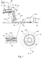
- Figure 1 shows a schematic drawing of one example of a way to perform, for example, the cleaning of a rainwater drain system 13, using the apparatus 10.
- the actual form of cleaning method which is practised outside the apparatus 10, in no way restricts the actual invention, or its applications, but instead other ways too of cleaning the drain network 13, or corresponding systems of flow channels are possible when applying the apparatus 10 and method.
- the applicability of the apparatus 10 according to the invention is not restricted to only the rainwater drains presented as an example of an application, but instead other types of flow channel requiring cleaning from time to time are possible subjects for servicing using the apparatus 10. Numerous kinds of these can be found, for example, in the industrial and municipal services sectors.
- the drain line system 13 is generally formed of a set of pipelines, which is formed of one or several pipes 30.1 - 30.3 joined to each other, or of a corresponding structure forming a flow channel.
- the diameter of the pipe 30.1 - 30.3 can normally be, for example, 200 - 1000 mm.
- the pipeline 30.1 - 30.3 can be cut by manholes 34.1, 34.2, which are at a distance from each other. Conventionally, it is possible at one time to service a drain line 30.2 between two consecutive manholes, 34.1, 34.2, by flushing it with a wash liquid 42, the main component of which is conventionally water.
- the drain line 30.2 is washed, i.e. cleaned, for example, of material 32 (cross-section A-A of Figure 1 ) that has adhered to its internal surface 38, and thus accumulated.
- the material 32 can be, for example, mineral in composition, such as sand and/or clay.
- One example of a way to perform the washing of the drain line 30.2 is to feed a flushing hose 36.1 into the pipeline 30.2.
- the flushing hose 36.1 in the pipe 30.2 sunk into the ground 33 is shown in the inset in the lower part of Figure 1 and next to the inset of the corresponding cross-section A-A of Figure 1 .
- the feeding of the flushing hose 36.1 into the drainpipe 30.2 can take place from a latter manhole 34.2 in the flow direction of the line 13.
- the wash liquid 42 loaded in connection with the apparatus 10 is pressurized and led into the flushing hose 36.1.
- the flushing hose 36.1 led into the preceding manhole 34.1 upstream in the drain line 13 to the service manhole 34.2, can be a special, as such known, nozzle (not shown), which guides the wash liquid 42 back into the drainpipe 30.2. This permits the wash liquid 42 to return from the upstream manhole 34.1 to the service manhole 34.2.
- this can happen already in the flushing-hose 36.1 feeding stage, in which case the end of the flushing hose 36.1 will move in the drainpipe 30.2 towards the upstream service manhole 34.1.
- the material 32 detaches from the internal surface 38 of the pipe 30.2, due to the high-pressure wash water 42, and becomes sludge in the water 42 and is thus flushed back to the service manhole 34.2 along with the wash water 42.
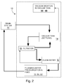
- FIG. 2 shows a rough schematic diagram of the basic principle of the apparatus 10 and method according to the invention.
- the drain-servicing apparatus 10 according to the invention can be built, for example, on a truck 11.
- the apparatus 10 can be used to wash a drainpipe 30.1 - 30.3 with high-pressure water 42 and correspondingly to remove solids 32 detached by flushing water 42 and turned into sludge, i.e. liquid 41 with a solids content, that has accumulated in the drain 13 and/or manholes 34.1, 34.2.
- the removal can be performed, for example, by vacuum, in which the liquid 41 is sucked from the drain system into a vacuum tank 14 arranged in connection with the apparatus 10.
- Pumping can be another way to move the liquid 41 from the drain system 13 to the vicinity of the apparatus 10.
- One embodiment of the apparatus 10 can include, as basic functionalities, means 44 - 48 for creating a vacuum in the vacuum tank 14, the vacuum tank 14 itself, in which the pre-cleaning, for example gravity settling, of the liquid 41 with a solids content, sucked from the drain system 13 can be performed, a fine-cleaning process, following the pre-cleaning and external to the tank 14, being, for example, a mesh-screen-filtering functionality 16, for cleaning the liquid that has settled in the vacuum tank 14 and is thus pre-cleaned and for circulating it in the apparatus, a clean-water tank 12 for storing seed water and the water 42 that has gone through the mesh-screen filtration process 16, and wash liquid 42 pressurization and feed 15, 61 to the drain system 13.
- the pre-cleaning for example gravity settling
- a fine-cleaning process following the pre-cleaning and external to the tank 14
- a mesh-screen-filtering functionality 16 for cleaning the liquid that has settled in the vacuum tank 14 and is thus pre-cleaned and for circulating it in the apparatus
- Figure 3 shows one example embodiment of the apparatus 10 for servicing, more specifically cleaning, a drain system 13. It should be noted that all the functionalities, which the apparatus 10 according to the invention may require in order to operate, may not necessarily be shown in Figure 3 . All kinds of functionalities, obvious to one skilled in the art, such as part of the apparatus's 10 temperature, pressure, and surface-level measurements, and also some of the valves, have been omitted from the schematic figure, in order to clarify the basic principle of the invention.
- the apparatus 10 includes a possible first tank 12 for the wash liquid 42, such as water, to be fed to the drain system 13, 30.2, and, in addition, a second tank, which is in this case a vacuum tank 14, for the liquid 41 containing solids 32, to be sucked out of the drain system 13, 30.2.
- the vacuum tank 14 can have a capacity of, for example, 10 m 3 .
- Means 15 on the pipelines 58, 37 are connected to the tanks 12, 14 for pressurizing the wash liquid 42 and feeding it into the drain system 13, 30.2, and also means 44 - 48 for removing the liquid 41 from the drain system 13, 30.2, 34.1 to the vacuum tank 14.
- the liquid 41 containing solids sucked from the drain system 13, 30.2 to the vacuum tank 14 is cleaned continuously of the solids 32 forming a sludge in it, in order to re-circulate the wash liquid 42 several times in the apparatus 10.
- the vacuum i.e. suction tank 14 can have been compartmentalized into at least two chambers, i.e. a settling chamber 17 and a pump chamber 18 connected to it.
- the pump chamber 18 connected to it can have a capacity of, for example, 2 m 3 .
- the liquid 41 containing solids, which has been sucked from the drain system 13, of which the wash liquid 42 forms at least a part can be preliminarily cleaned, for example, by gravity.
- the internal implementation of the vacuum tank 14 is simple in the extreme. Most of the internal space of the vacuum tank 14 is reserved for the liquid 41, containing solids, sucked into it and there are few moving objects, or those requiring servicing, inside the vacuum tank 14.
- the mesh-screen filtration process 16 arranged outside the vacuum tank 14 and the circulation of the liquid through it permits, for its part, the continuous cleaning of the wash water, and thus also the continuous flushing/washing of the drain system 13.
- the washing of the drain system 13 need not be interrupted at times, for example, for cleaning runs of the wash water.
- one or more submersible pumps 19, suitable for sludge operation can be used as a transfer pump in the pump chamber 18 of the vacuum tank 14.
- a pump 19 is the Mamec LL-2003H, running at a minimum of 2500 r/min.
- the pump 19 the preliminarily cleaned wash liquid in the settling chamber 17 is moved from the pump chamber 18 to the mesh-screen filtration process 16 after and outside the vacuum tank 14, by means of which the liquid 41 removed from the drain system 13, 30.2, 34.2 to the second tank 14 is cleaned, in order to circulate it in the apparatus 10.
- there is also a bypass flow line 50, 56 by means of which the preliminarily cleaned liquid with a solids content can be returned to the settling chamber 17 of the vacuum tank 14 bypassing the mesh-screen filtration process 16.
- the mesh-screen filter process 16 is based on dynamic mesh-screen filtering 20 in a surprising way and is implemented between the first tank 12 and the second tank 14.
- dynamic filtering refers to a state of motion, which is actively created in the filtering means 20.
- the external mesh-screen filtering arrangement 16 of the vacuum tank 14 includes at least one mesh-screen filter 20.
- the mesh-screen filter 20 based on through-flow can rotate, thus making it dynamic. It will then remain better and longer in good condition.
- FIG 4 shows in slightly greater detail one embodiment of mesh-screen filtering 16, seen as longitudinal and transverse sections in different directions.
- the dynamic mesh-screen filtering 16 includes a horizontal cylindrical drum 20 rotating around its central axis, the liquid 41 removed from the drain system 13, 30.2, 34.2 being arranged to travel through a filter jacket 20' fitted to the circumference of the drum, the direction of its flow being thus from the outside of the drum 20 to the inside.
- One example of the dimensions of the drum 20 is a diameter of 200 - 500 mm, for example 300 mm, and a length of 1000 - 3000 mm, for example 1500 mm.
- the drum 20 can be rotated through its central shaft, for example, by an electric motor or similar (not shown).
- the speed of rotation of the drum can be, for example, 5 - 20 r/min, for example 10 r/min.
- the frame structure of the drum 20 can be galvanized while on its circumference there is a sieve screen 20' of, for example, stainless steel, which filters the liquid flowing through the jacket 20' into the drum 20.
- the drum 20 is fitted in a chamber separate from the vacuum tank 14, which in this case is a trough 80.
- the chamber can also be covered.
- Water-distribution elements 82 connected to the tank 14 over a pipeline 87 are fitted to the trough 80.
- the water distribution element can be a manifold 82 equipped with nozzles, which is fitted to the lower part 81 of the trough 80, and which distributes the liquid 41 to be filtered to the trough 80.
- the flow of the liquid 41 to be filtered to the trough 80 can be regulated from the filtering trough 80 by means of surface-level upper-limit sensors (not shown) for the liquid 41 and the wash-water tank 12. If the surface L of the water rises to a set surface level in the trough 80, or in the tank 12, most of the flow of the submersible pump 18 can be led from the branch 21 to an exit pipe 35 and thus back to the drain system 13 ( Figure 3 ).
- the filter jacket 20' can be washed in connection with the operation of the apparatus 10, in order to maintain the functioning of the mesh-screen filtration process 16 and to improve the continuity of operation of the filtration process 16.
- One way to wash the filtering jacket 20' is to arrange wash jets 84 inside the drum 20.
- a wash-water line 86 can be brought, for example, to the end of the drum 20, and the line continued inside the drum 20 as an elongated sparge pipe 83, in which there are nozzles for spraying the water against the internal surface of the filtering jacket 20'.
- the sparge pipe 83 can be, for example, on the central axis of the drum 20, or close to it.
- the filtering jacket 20' of the drum 20 can be washed at a point, which is above the water level L of the trough 80.
- the point of impact of the wash jets 84 on the jacket 20' of the drum 20 changes, because the drum 20 rotates in the direction of its circumference.
- the water jets 84 detach the solids from the jacket 20', which then drop to the lower part 81 of the trough 80.
- the mesh-screen filter 20 can be kept from freezing by means of, for example, a heating apparatus based on liquid circulation, which will permit safe, fully effective work, even in a cold environment.
- the heating energy can be taken, for example, to a heat-exchanger structure 88 fitted to the bottom 81 of the trough 80, by circulating a heated non-freezing heating liquid through it ( Figure 4 ).
- a metal trough 80 for example, will remain unfrozen during work and during breaks in work.
- the pump cabin 18 too can be heated.
- the mesh size of the filtering surface 20' of the mesh-screen filter 20 can be, for example, 100 micron, more generally 50 - 300 micron.
- a dynamic mesh-screen filtration process 16 as well as the principally continuous washing of the mesh-screen filter 20
- the advantages of not using chemicals are, among others, the simplicity of the mesh-screen filtration process 16, a reduced need for skill in the operator of the apparatus 10, and a higher filtering capacity.
- the wash water strained through the mesh-screen filter 20, and thus also mostly cleaned of solids, is removed from the drum 20, for example, through a pipe connection 89 attached to its end, and is pumped by a pump 54 along a pipeline 55 back to the operating water tank 12 of the apparatus 10 for reuse and pressurization for feeding to the drain 13.
- the cleaned wash liquid 42 can be fed, not only, or instead of to the operating water tank 12, directly to the pressurization process 15, 59 - 62.
- the embodiment with an operating water tank according to Figure 3 is, however, more advantageous.
- the cleaning flushing water 42 can be fed without worry to the high-pressure pump 15, without its operation suffering, or the operating components of the pressurization circuit 15, 59 - 62 being damaged. It should be noted that the 'absolute' cleanliness demanded in, for example, virgin water is not necessarily required in the wash water cleaned in the mesh-screen filtration process 16 and fed to the high-pressure pump 15, but instead small impurities can be allowed, the effect of which in the operation of the pressurization circuit 15, 59 - 62 is non-existent.
- the filtration process 16 which functions without chemicals, can operate as a continuous process simultaneously with normal drain-servicing work, in which high-pressure wash liquid 42 is fed to the drain 13 and liquid 41 with a solids content is sucked mainly simultaneously out of the drain 13 to a sludge tank 14 in connection with the apparatus 10.
- the cleaning based on mesh-screen filtering is extremely reliable in operation and ensures a good cleaning result.
- connection 21 between the pump chamber 18 of the vacuum tank 14 and the fine-filtering 16.
- Part of the preliminarily cleaned sludge that may have settled is returned through the connection 21 to the drain system 13 through the pipe 35.
- the discharge of the excess reject water 39 can be led elsewhere than to the work point 34.2. It can be discharged downstream of the drain system 13, for example, into the next service manhole 34.3 about 100 m from the service point.
- the pipe 35' shown by a broken line in Figure 1 shows this application. This allows the drain line 30.3 following the service point 34.2 too to be shut off for servicing and repair, without interfering with the normal use of the drain 13. In other words, the apparatus 10 then replaces the drain line 30.3 in question.
- the compartmentalization of the settling chamber 17 of the vacuum tank 14 into at least two spaces can have been achieved by means of a single hinged partition 24.
- the partition 24 can open under its own weight, turning out of the road when the vacuum tank 14 is tipped to empty it of the sludge collected in it.
- the continuation of the hinged partition 24 can be a fixed wall, which extends, for example, to 250 mm from the roof of the tank 14.
- the partition 24 can lessen the disturbances in the liquid in the tank 14, for example, when using the vehicle 11 to move it from one place to another.
- the partition 24, which is easily opened is sure to move out of the way of the solids collected in the front part of the settling chamber 17, but will nevertheless be sure to hold the solids collected on the bottom of the settling tank 17, in rear part of the settling tank 17.
- the settling chamber 17 and the pump chamber 18 of the vacuum tank 14 may be separated from each other by a partition 26 equipped with an overflow 25.
- the distance between the upper part of the partition 26 and the upper part of the tank 14 can be, for example, 100 mm.
- the connection means can include a set of curved tubes 27, which can be arranged in the maintenance hatch 28 of the pump chamber, 18. They can then be easily changed if necessary while the addition of new tubes is simple.
- the ends of the tubes 27 on the settling-chamber 17 side can be arranged relative to the minimum depth of the liquid in the chamber 17 in such a way that the liquid travelling into the pump chamber 18 through the tubes 27 is taken from beneath the surface of the liquid. Thus rubbish floating in the chamber 17, for example, cannot travel to the transfer pump 19 and the transfer pump 19 can thus be in the tank 14.
- the vacuum connection 29 of the vacuum tank 14 can be in connection with the pump chamber 18 of the vacuum tank.
- a vacuum-creation line the means of which can include a shut-off ball valve 44, a water separator 45, and a suction pump 46 with threads, a suction filter 47, and a sound attenuator 48.
- a suction filter 47 is the AFIU-910, 150 micr., of which there can be two.
- One example of the suction pump 46 can be the Hibon VTB-820, 2400 m 3 /h.
- the following describes one example of an application of the means for pressurizing the liquid 42 and feeding it to the drain system 13, 30.2.
- water is taken from the wash-water tank 12 to the high-pressure pump 15, the water 42 pressurized by which being led into the selected flushing hose 36.1.
- the flushing-water tank 12 can be integrated on the roof of the vacuum tank 14. In that case, the tank 12 can form a rectangular prism dividing the vacuum tank 14 longitudinally on each side of its divided upper part.
- a pipeline 58 can be connected to the upper parts of both halves of the tank, in order to lead the wash water for pressurization.
- An example of the sequence in the line 58 is: filling valve / suction pipe shut-off valve 59 of the tank 12, suction filter 60, feed-water pump 61, pressurizing water pump 15, pressure regulator 62, and flushing-hose reels 57.1, 57.2, of which there are two in this case.
- the suction filter 60 can be formed of two AFIU-910, 80 micron filters
- the feed-water pump 61 can be, for example, Grundfoss
- the pressurizing water pump 15 can be, for example, Woma 150 ARP (329 1/min, 170 bar)
- the pressure regulator 62 can be, for example, 170 bar.
- the apparatus can include a compressed-air feed valve 67, which is connected to the high-pressure water pump 15 and the wash circuit of the mesh-screen filter 20.
- a compressed-air feed valve 67 which is connected to the high-pressure water pump 15 and the wash circuit of the mesh-screen filter 20.
- the diameter of the hose and the nozzle at the end of it is normally, for example, about 50 mm.
- the suction filter 60 For the washing of the screen 20' mesh-screen filter 20 and of the vacuum tank 14, there can be a connection in the pipeline after the suction filter 60, from which a pipeline branches off to the water pump 65 (for example, Speck, 68 1/min, 20 bar).
- the water pump 65 for example, Speck, 68 1/min, 20 bar.
- the prefilter 66 for the wash nozzles of the mesh-screen filter 20.
- the emptying valve 52 of the filtering chamber i.e. the chamber outside the drum 20
- the emptying valve 53 of the clean chamber i.e. the internal cylindrical chamber of the drum 20.
- the filtering chamber i.e.
- the trough 80 can be emptied even in the middle of the filtration process, i.e. in connection with the operation of the apparatus 10, for example, automatically in a timed manner, aided by vacuum, along the line 56 to the tank 14, if this is required. This feature too will improve the continuity of operation of the apparatus 10.
- the continuous cleaning improves the continuous operational readiness of the apparatus 10.
- the operation of the apparatus is then not interrupted by, for example, having to fetch clean wash liquid or empty the sludge tank 12, or even separate filtering runs of the wash liquid, during which the drain itself cannot be washed.
- Continuous operation is an important advantage for a wash-services provider for channel systems, because it is essential for the cost-intensive investment in cleaning vehicles to be in the most productive operation possible, in the most efficient manner.
Landscapes
- Engineering & Computer Science (AREA)
- Health & Medical Sciences (AREA)
- Life Sciences & Earth Sciences (AREA)
- Hydrology & Water Resources (AREA)
- Public Health (AREA)
- Water Supply & Treatment (AREA)
- Mechanical Engineering (AREA)
- Physical Water Treatments (AREA)
- Filtration Of Liquid (AREA)
- Cleaning In General (AREA)
Applications Claiming Priority (1)
| Application Number | Priority Date | Filing Date | Title |
|---|---|---|---|
| FI20075713A FI121632B (fi) | 2007-10-08 | 2007-10-08 | Laitteisto ja sen käyttö viemärin huoltamiseksi ja vastaava menetelmä |
Publications (2)
| Publication Number | Publication Date |
|---|---|
| EP2048293A2 true EP2048293A2 (de) | 2009-04-15 |
| EP2048293A3 EP2048293A3 (de) | 2012-12-12 |
Family
ID=38656860
Family Applications (1)
| Application Number | Title | Priority Date | Filing Date |
|---|---|---|---|
| EP08166069A Withdrawn EP2048293A3 (de) | 2007-10-08 | 2008-10-08 | Vorrichtung und Verfahren zur Wartung eines Kanals |
Country Status (2)
| Country | Link |
|---|---|
| EP (1) | EP2048293A3 (de) |
| FI (1) | FI121632B (de) |
Cited By (3)
| Publication number | Priority date | Publication date | Assignee | Title |
|---|---|---|---|---|
| JP2015224422A (ja) * | 2014-05-26 | 2015-12-14 | 株式会社モリタホールディングス | 吸引作業車 |
| EP3179001A1 (de) * | 2015-12-09 | 2017-06-14 | Botnetank AS | Verfahren und vorrichtung zur entwässerung von septischem schlamm |
| CN109653341A (zh) * | 2019-02-27 | 2019-04-19 | 白鹏飞 | 一种道路路边沟清理机 |
Citations (2)
| Publication number | Priority date | Publication date | Assignee | Title |
|---|---|---|---|---|
| US4134174A (en) | 1977-08-29 | 1979-01-16 | Super Products Corporation | Sewer and catch basin cleaner |
| WO2003095754A1 (en) | 2002-05-07 | 2003-11-20 | Cleanflow Technologies Pty Ltd | Conduit cleaning means |
Family Cites Families (3)
| Publication number | Priority date | Publication date | Assignee | Title |
|---|---|---|---|---|
| DE3908216A1 (de) * | 1989-03-14 | 1990-09-20 | Karl Wiedemann | Vorrichtung zur kanalreinigung |
| DE3911444A1 (de) * | 1989-04-07 | 1990-10-11 | Georg Klass | Feinfilter fuer die reinigung von fluessigkeiten |
| DE102004022749B4 (de) * | 2004-05-07 | 2012-11-29 | Karl Wiedemann | Vorrichtung zur Reinigung von Schmutzwasser |
-
2007
- 2007-10-08 FI FI20075713A patent/FI121632B/fi active IP Right Grant
-
2008
- 2008-10-08 EP EP08166069A patent/EP2048293A3/de not_active Withdrawn
Patent Citations (2)
| Publication number | Priority date | Publication date | Assignee | Title |
|---|---|---|---|---|
| US4134174A (en) | 1977-08-29 | 1979-01-16 | Super Products Corporation | Sewer and catch basin cleaner |
| WO2003095754A1 (en) | 2002-05-07 | 2003-11-20 | Cleanflow Technologies Pty Ltd | Conduit cleaning means |
Cited By (3)
| Publication number | Priority date | Publication date | Assignee | Title |
|---|---|---|---|---|
| JP2015224422A (ja) * | 2014-05-26 | 2015-12-14 | 株式会社モリタホールディングス | 吸引作業車 |
| EP3179001A1 (de) * | 2015-12-09 | 2017-06-14 | Botnetank AS | Verfahren und vorrichtung zur entwässerung von septischem schlamm |
| CN109653341A (zh) * | 2019-02-27 | 2019-04-19 | 白鹏飞 | 一种道路路边沟清理机 |
Also Published As
| Publication number | Publication date |
|---|---|
| FI20075713A0 (fi) | 2007-10-08 |
| FI121632B (fi) | 2011-02-15 |
| EP2048293A3 (de) | 2012-12-12 |
| FI20075713L (fi) | 2009-04-09 |
Similar Documents
| Publication | Publication Date | Title |
|---|---|---|
| JP3369732B2 (ja) | 廃水、特に雨水の処理装置 | |
| KR102018647B1 (ko) | 오수 처리차 | |
| US20080087591A1 (en) | System for treating wastewater | |
| US5093012A (en) | Water reclamation system and method | |
| EP2048293A2 (de) | Vorrichtung und Verfahren zur Wartung eines Kanals | |
| KR101562757B1 (ko) | 비점오염저감시설 | |
| KR101638559B1 (ko) | 슬러지를 여과하여 건조시키는 비점오염저감시설 | |
| KR20090089542A (ko) | 취수용 물탱크 | |
| KR101080805B1 (ko) | 합류식 하수관거 월류수 처리장치 및 방법 | |
| US5223150A (en) | Water reclamation system and method | |
| KR101463479B1 (ko) | 계곡수 정화용 간이 상수도 장치 | |
| KR101058919B1 (ko) | 초기우수처리시설 및 초기우수처리방법 | |
| USRE35871E (en) | Water reclamation system and method | |
| JP6727027B2 (ja) | 沈砂池の除砂装置 | |
| JP2017000989A (ja) | し渣洗浄装置及びその運転方法 | |
| CN213994930U (zh) | 一种高效沉淀池用冲洗系统 | |
| KR101995494B1 (ko) | 여재층을 구비하여 유지관리가 용이한 우수처리장치 | |
| JP4569870B2 (ja) | ポンプ井の異物排出方法並びに異物排出装置 | |
| JP2003027533A (ja) | 雨水及び浴槽水再利用装置 | |
| CN207295943U (zh) | 一种道路排水系统 | |
| SU1182150A1 (ru) | Установка дл очистки жидкости | |
| JP4006757B2 (ja) | 除砂システム | |
| KR101788788B1 (ko) | 취수로의 이물질제거장치 | |
| KR102230826B1 (ko) | 침사 제거기 | |
| CN213348091U (zh) | 一种罐装车冲洗水循环利用装置 |
Legal Events
| Date | Code | Title | Description |
|---|---|---|---|
| PUAI | Public reference made under article 153(3) epc to a published international application that has entered the european phase |
Free format text: ORIGINAL CODE: 0009012 |
|
| AK | Designated contracting states |
Kind code of ref document: A2 Designated state(s): AT BE BG CH CY CZ DE DK EE ES FI FR GB GR HR HU IE IS IT LI LT LU LV MC MT NL NO PL PT RO SE SI SK TR |
|
| AX | Request for extension of the european patent |
Extension state: AL BA MK RS |
|
| PUAL | Search report despatched |
Free format text: ORIGINAL CODE: 0009013 |
|
| AK | Designated contracting states |
Kind code of ref document: A3 Designated state(s): AT BE BG CH CY CZ DE DK EE ES FI FR GB GR HR HU IE IS IT LI LT LU LV MC MT NL NO PL PT RO SE SI SK TR |
|
| AX | Request for extension of the european patent |
Extension state: AL BA MK RS |
|
| RIC1 | Information provided on ipc code assigned before grant |
Ipc: E03F 7/10 20060101AFI20121106BHEP |
|
| AKY | No designation fees paid | ||
| REG | Reference to a national code |
Ref country code: DE Ref legal event code: R108 |
|
| REG | Reference to a national code |
Ref country code: DE Ref legal event code: R108 Effective date: 20130821 |
|
| STAA | Information on the status of an ep patent application or granted ep patent |
Free format text: STATUS: THE APPLICATION IS DEEMED TO BE WITHDRAWN |
|
| 18D | Application deemed to be withdrawn |
Effective date: 20130613 |