EP2047788A1 - Endoskopsystem - Google Patents
Endoskopsystem Download PDFInfo
- Publication number
- EP2047788A1 EP2047788A1 EP07767069A EP07767069A EP2047788A1 EP 2047788 A1 EP2047788 A1 EP 2047788A1 EP 07767069 A EP07767069 A EP 07767069A EP 07767069 A EP07767069 A EP 07767069A EP 2047788 A1 EP2047788 A1 EP 2047788A1
- Authority
- EP
- European Patent Office
- Prior art keywords
- endoscope
- endoscopic system
- input
- endoscopic
- view
- Prior art date
- Legal status (The legal status is an assumption and is not a legal conclusion. Google has not performed a legal analysis and makes no representation as to the accuracy of the status listed.)
- Granted
Links
Images


Classifications
-
- A—HUMAN NECESSITIES
- A61—MEDICAL OR VETERINARY SCIENCE; HYGIENE
- A61B—DIAGNOSIS; SURGERY; IDENTIFICATION
- A61B1/00—Instruments for performing medical examinations of the interior of cavities or tubes of the body by visual or photographical inspection, e.g. endoscopes; Illuminating arrangements therefor
- A61B1/00064—Constructional details of the endoscope body
- A61B1/00066—Proximal part of endoscope body, e.g. handles
-
- A—HUMAN NECESSITIES
- A61—MEDICAL OR VETERINARY SCIENCE; HYGIENE
- A61B—DIAGNOSIS; SURGERY; IDENTIFICATION
- A61B1/00—Instruments for performing medical examinations of the interior of cavities or tubes of the body by visual or photographical inspection, e.g. endoscopes; Illuminating arrangements therefor
- A61B1/00002—Operational features of endoscopes
- A61B1/00039—Operational features of endoscopes provided with input arrangements for the user
- A61B1/0004—Operational features of endoscopes provided with input arrangements for the user for electronic operation
-
- A—HUMAN NECESSITIES
- A61—MEDICAL OR VETERINARY SCIENCE; HYGIENE
- A61B—DIAGNOSIS; SURGERY; IDENTIFICATION
- A61B1/00—Instruments for performing medical examinations of the interior of cavities or tubes of the body by visual or photographical inspection, e.g. endoscopes; Illuminating arrangements therefor
- A61B1/00002—Operational features of endoscopes
- A61B1/00059—Operational features of endoscopes provided with identification means for the endoscope
-
- A—HUMAN NECESSITIES
- A61—MEDICAL OR VETERINARY SCIENCE; HYGIENE
- A61B—DIAGNOSIS; SURGERY; IDENTIFICATION
- A61B1/00—Instruments for performing medical examinations of the interior of cavities or tubes of the body by visual or photographical inspection, e.g. endoscopes; Illuminating arrangements therefor
- A61B1/00064—Constructional details of the endoscope body
- A61B1/00105—Constructional details of the endoscope body characterised by modular construction
-
- A—HUMAN NECESSITIES
- A61—MEDICAL OR VETERINARY SCIENCE; HYGIENE
- A61B—DIAGNOSIS; SURGERY; IDENTIFICATION
- A61B1/00—Instruments for performing medical examinations of the interior of cavities or tubes of the body by visual or photographical inspection, e.g. endoscopes; Illuminating arrangements therefor
- A61B1/04—Instruments for performing medical examinations of the interior of cavities or tubes of the body by visual or photographical inspection, e.g. endoscopes; Illuminating arrangements therefor combined with photographic or television appliances
-
- G—PHYSICS
- G02—OPTICS
- G02B—OPTICAL ELEMENTS, SYSTEMS OR APPARATUS
- G02B23/00—Telescopes, e.g. binoculars; Periscopes; Instruments for viewing the inside of hollow bodies; Viewfinders; Optical aiming or sighting devices
- G02B23/24—Instruments or systems for viewing the inside of hollow bodies, e.g. fibrescopes
- G02B23/2476—Non-optical details, e.g. housings, mountings, supports
- G02B23/2484—Arrangements in relation to a camera or imaging device
Definitions
- the present invention relates to an endoscopic system having an electronic endoscope inserted in a body cavity to perform an endoscopic inspection and a display device for displaying an endoscopic image of the interior of the body cavity taken with the electronic endoscope.
- Medical endoscopes have been used for endoscopic inspections by being inserted into body cavities.
- electronic endoscopes have been known that take endoscopic images of the interiors of body cavities using an image pickup device or the like and display the images on a monitor.
- An endoscopic image taken with such an electronic endoscope is recorded as an inspection recording on a film photograph or a recording medium.
- this recording is performed, there is a need to correctly record, for identifying a subject, various sorts of information including information on the patient subjected to the endoscopic inspection and the date of inspection.
- Japanese Patent Application Laid-Open Publication No. 7-111976 discloses an electronic endoscope apparatus capable of displaying the above-described sorts of information as character lines on a monitor screen.
- the conventional electronic endoscope apparatus requires inputting the above-described sorts of information by means of a keyboard connected to a processor. It is, therefore, necessary for the conventional electronic endoscope apparatus to have a processor to which an electronic endoscope is wired and a space for placement of a keyboard as well as a monitor.
- the processor can be placed only at a position close to the electronic endoscope.
- the keyboard connected to the processor must also be placed in the vicinity of the processor and the electronic endoscope.
- hygienic management on the keyboard in particular is required before and during an operation, because the above-described various sorts of information are manually inputted through the keyboard. Therefore, an infection prevention measure using an antimicrobial coating or a bacteria blocking cover on the keyboard is taken.
- an object of the present invention is to provide an endoscopic system which is so compact as not to be an obstacle in a user manipulation action region, and which enables a user to easily input various sorts of information.
- the present invention provides an endoscopic system including an endoscope having an input portion, a monitor which displays an image taken with the endoscope, an observation apparatus which is detachably attached to the endoscope, and which, when connected to the endoscope, automatically displays on the monitor a setting view on which a setting can be made through the input portion.
- Figs. 1 to 9 relates to a description of a first embodiment of an endoscopic system according to the present invention.
- Fig. 1 is an entire configuration diagram showing the endoscopic system.
- Fig. 2 is a plan view showing a monitor screen activated when an electronic endoscope and an observation apparatus are connected to each other.
- Fig. 3 is a plan view showing the monitor screen when patient information is inputted in Japanese (by kana-kanji conversion).
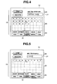
- Fig. 4 is a plan view showing the monitor screen when patient information is input in alphabetic character form.
- Fig. 5 is a plan view showing the monitor screen when patient information is inputted in numeric form.
- Fig. 6 is a plan view showing the monitor screen when a confirmation view is displayed after input of patient information.
- Fig. 1 is an entire configuration diagram showing the endoscopic system.
- Fig. 2 is a plan view showing a monitor screen activated when an electronic endoscope and an observation apparatus are connected to each other.
- Fig. 3 is a plan
- FIG. 7 is a plan view showing a first modified example and showing the monitor screen when patient information is inputted in Japanese (by kana-kanji conversion).
- Fig. 8 is a plan view showing a second modified example and showing the monitor screen when patient information is inputted in Japanese (by kana-kanji conversion) by means of a touch panel system, while an endoscopic image is being displayed in the background.
- Fig. 9 is a plan view showing a third modified example and showing a configuration of a software keyboard.
- an endoscopic system 1 in the present embodiment is configured of an electronic endoscope 2 (hereinafter referred to simply as endoscope), an observation apparatus 10, which is a camera control unit (CCU), and a monitor 13, which is a display device.
- endoscope an electronic endoscope 2
- observation apparatus 10 which is a camera control unit (CCU)
- monitor 13 which is a display device.
- the endoscope 2 is configured of in order from the distal end, a distal end portion 3, an insertion portion 4 formed continuously with the distal end portion, an operation portion 5 connected to a proximal end of the insertion portion 4, and a universal cord 7, which is an electric cable extending from the operation portion 5.
- the distal end portion 3 of the endoscope 2 is provided with an image pickup unit not shown in the figure.
- the image pickup unit incorporates illumination means and image pickup means in the present embodiment.
- the illumination means of the image pickup unit is configured, for example, as an LED serving as a light source in itself or configured to radiate light by guiding illumination light from an external light source through a light guide fiber passed through the insertion portion 4, the operation portion 5 and the universal cord 7.
- an image pickup device e.g., a CCD or CMOS is used.
- the image pickup means is configured to take an endoscopic image through the distal end portion 3 or an image guide fiber.
- the insertion portion 4 is a flexible endoscope insertion portion or a rigid endoscope insertion portion. If the insertion portion 4 is the flexible endoscope insertion portion, it may have a bending portion in its distal end portion.
- the operation portion 5 is provided with an operating lever 6, which is a joystick-type input portion provided as a pointing device.
- the operating lever 6 is not limited to a joystick-type pointing device.
- the operating lever 6 may be a track ball.
- the universal cord 7 has a connection portion 8 at its extended end.
- the connection portion 8 is detachably connected electrically to the observation apparatus 10.
- a detection chip 9, which is a component part to be detected, is incorporated in the connection portion 8.
- the observation apparatus 10 incorporates a detection device 11, which is a detection portion for detecting the detection chip 9 when the connection portion 8 is electrically connected, a recording device 12, which records endoscopic images taken with the above-described electronic endoscope 2, and a processor (not shown).
- the detection device 11 simply recognizes having detected the connection portion 8 of the universal cord 7.
- the detection device 11 may be a device for electrically detecting the above-described detection chip 9 or a mechanical connection detection switch.
- the recording device 12 in the present embodiment is a device capable of writing the above-mentioned endoscopic images on recording medium, e.g., a hard disk, any of various types of disks, a flash memory, or any of various types of picture cards.
- the recording device 12 may be externally mounted instead of being limited to the one incorporated in the observation apparatus 10.
- the processor (not shown) performs image processing on a photoelectrically converted image signal from the endoscope 2 to enable the signal to be displayed as an endoscopic image on a monitor 13.
- a detection signal from the detection device 11 is inputted to the processor.
- the monitor 13 is connected to the observation apparatus 10 and displays endoscopic images and various setting views on a monitor screen 14.
- a user who is an operator, first prepares the endoscopic system 1 for endoscopic inspection. At this time, the user connects the endoscope 2 and the observation apparatus 10 to each other. That is, the user couples and connects the connection portion 8 of the universal cord 7 of the endoscope 2 to the observation apparatus 10 at a predetermined connection position on the observation apparatus 10.
- the detection device 11 in the observation apparatus 10 detects the detection chip 9 in the connection portion 8 and outputs the detection signal to the processor.
- An initial setting view such as shown in Fig. 2 is then displayed (activated) on the monitor screen 14.
- the group of setting tabs 15 are displayed at the left-hand side of the monitor screen 14, while the display portions 17 to 19 are displayed at the right-hand side of the monitor screen 14.
- a selecting pointer 16 freely operable with the operating lever 6 provided on the operation portion 5 of the endoscope 2 is also displayed.
- the selecting pointer 16 is moved in the monitor screen 14 by being linked to the operation of the operating lever 6.
- the user moves the selecting pointer 16, for example, onto the patient setting input in the group of setting tabs 15, as shown in Fig. 2 , and depresses the operating lever 6 to change the display to a patient information setting view.
- An input item display portion 20 and an input cell 21 are then displayed in an upper right portion of the monitor screen 14, and a software keyboard 23 having hiragana character lines and a group of change keys 24 including a plurality of change keys are displayed (activated) from a central portion to a lower portion.
- the software keyboard 23 and the group of change keys 24 are displayed in a transparent display manner as shown in Fig. 3 , such that the group of setting tabs 15 in the menu view shown in Fig. 2 are displayed in the background.
- the user moves the selecting pointer 16 onto one of the hiragana characters that he or she wants to select on the hiragana character software keyboard 23 formed of an array of the kana syllabary by operating the operating lever 6 on the operation portion 5 when inputting a patient name in Japanese, and depresses (clicks) the operating lever 6.
- the selected hiragana character is then displayed in the input cell 21, as shown in Fig. 3 .
- the user wants to convert the hiragana character into a kanji or a katakana character, he or she places on the kanji key or the kana key in the group of change keys 24 and depresses (clicks) the operating lever 6. If the user wants to convert the selected hiragana character into a small letter, he or she can convert the selected character by again (double) clicking the selected character or by clicking the small letter on the software keyboard 23. If the user wants to input a space, he or she can do so by selecting a space key in the group of change keys 24. Further, conversion candidates for the converted kanji are successively displayed by clicking the kanji key in the group of change keys 24.
- alphabet (English character) input and numeral input can also be performed by selecting an alphabetic character key or a numeral key in the group of change keys 24.
- the software keyboard 23 is changed for another having alphabetic character lines, as shown in Fig. 4 .
- the user can then input a patient name in the alphabet by moving the selecting pointer 16 to each of the alphabetic characters that he or she wants to select and by depressing (clicking) the operating lever 6, as he or she does in the case of inputting hiragana characters.
- the software keyboard 23 is changed for another having numeric character lines, as shown in Fig. 5 .
- the user can input any of various IDs in numeric form by moving the selecting pointer 16 to each of the numeric characters that he or she wants to select and by depressing (clicking) the operating lever 6.
- the above-mentioned various IDs include a patient ID, a doctor ID, an endoscope ID and a management ID of the recording medium on which a recording is made.
- the character information inputted by means of the software keyboard 23 is written to the recording medium in the recording device 12 in the observation apparatus 10 along with the endoscopic image.
- the input items are changed in order of a patient name and a patient ID.
- a determination key in the group of change keys 24 after inputting characters for the corresponding information, a change to a next input item is made.
- the user can also make a return to the immediately preceding input item by selecting a return key in the group of change keys 24.
- a group of change keys 24a including an enter key, a change key, a menu key, a return key and a close key are displayed in a lowermost portion of the monitor screen 14. While in the present embodiment only a patient name, a patient ID and a date are shown in Fig. 6 , various sorts of information such as a doctor ID and an endoscope ID may also be displayed.
- the user wants to switch from this initial view to an endoscopic image he or she can do so by selecting the close key in the group of change keys 24a. Also, if the user wants to change some of the various sorts of information inputted, he or she can select the change key in the group of change keys 24a or again select the patient information input tab in the group of setting tabs 15 to change the information by the above-described procedure.
- the endoscopic system 1 in the present embodiment enables the above-described various sorts of information to be inputted by means of the operating lever 6 provided on the operation portion 5 of the endoscope 2, by selecting from the group of setting tabs 15 displayed on the monitor screen 14 and by inputting from the software keyboard 23, even though the observation apparatus 10 is provided with no such input device as a keyboard.
- the endoscopic system 1 can be configured in a compact form without requiring any additional input device.
- the endoscopic system 1 in the present embodiment does not reduce the in-hospital space in which treatments are made and does not place any input device for inputting various sorts of information as an obstacle in a manipulation action region close to a patient. As a result, a user who is a doctor can easily perform manipulations.
- the endoscopic system 1 in the present embodiment does not require any input device, a sterilization treatment may be performed only on the endoscope 2 after the operation. Therefore, sterilized endoscopes 2 may be simply connected at the time of continuous endoscopic inspection, thus improving the availability factor of the endoscopic system 1.
- the software keyboard 23 may be configured to have only the characters at the heads of the a- to wa-rows displayed, as shown in Fig. 7 , and to enable selection from the characters by displaying, for example, the characters in the a-row (a to o) when the selecting pointer 16 is placed on the a-row head character (a).
- the software keyboard 23 thus configured is capable of increasing the display area in the background view.
- the software keyboard 23 may alternatively be of a touch panel type, such that selection can be made with finger F, as shown in Fig. 8 .
- the input item display portion 20, the input cell 21, the software keyboard 23 and the group of change keys 24 may be configured to enable display of the background view on an endoscopic image 25 as well, as shown in Fig. 8 , as well as to enable input of various sorts of information.
- a software keyboard 23a may be configured to enable characters in one of various character lines to be selected one after another each time the corresponding character line key is selected by being clicked, as shown in Fig. 9 . More specifically, any one of the characters in each of the a- to wa-rows can be selected according to the number of times the corresponding key is clicked. Input of alphabetic or numeric characters is enabled by selecting an alphabetic character or a numeric character in a group of change keys 24b, and selection can be made according to the number of times the displayed character is clicked.
- Figs. 10 and 11 relates to a description of a second embodiment of the endoscopic system according to the present invention.
- Fig. 10 is an entire configuration diagram showing the endoscopic system.
- Fig. 11 is a plan view showing a monitor screen activated when an electronic endoscope and an observation apparatus are connected to each other, and when an insertion portion and an operation portion of the electronic endoscope are connected to each other.
- An endoscope 2 in an endoscopic system 1 in the present embodiment is configured so that an insertion portion 4 and an operation portion 5 are detachably connected to each other.
- the same reference numerals are used for the same configuration as that of the above-described endoscopic system 1 in the first embodiment, and the detailed description of the same configuration will not be repeated.
- the insertion portion 4 of the endoscope 2 has an insertion portion connector 27 on its proximal end portion.
- the insertion portion connector 27 incorporates an ID chip 28 in which an endoscope ID is recorded and is connected to the operation portion 5.
- the operation portion 5 incorporates a detection portion 29 with which the ID chip 28 in the insertion portion connector 27 is read.
- the detection portion 29 is electrically connected to an observation apparatus 10 via a universal cord 7.
- the insertion portion 4 in the present embodiment is of a one-time-use (disposable) type, is used for each patient and is subjected to medical disposal after being used. Needless to say, the insertion portion 4 may alternatively be of a reusable type.
- connection portion 8 of the universal cord 7 of the endoscope 2 is connected to the observation apparatus 10 before endoscopic inspection, as is that in the first embodiment.
- the insertion portion connector 27 of the insertion portion 2 is also connected to the operation portion 29.
- the detection portion 29 in the operation portion 5 detects the ID chip 28 in the insertion portion connector 27 and outputs information on the completion of connection between the insertion portion 4 and the operation portion 5 and endoscope ID information stored in the ID chip 28 to the observation apparatus 10.
- An initial setting view such as shown in Fig. 11 is then displayed (activated) on the monitor screen 14, as is that in the first embodiment.
- An endoscope ID number which is identification information, is automatically displayed in an endoscope ID (SCOPE ID) display portion 30 below the date/time display portion 19 of the monitor screen 14.
- identification information for identifying a state after use is written to the ID chip 28 from the detection portion 29 when the insertion portion 4 is connected to the operation portion 5.
- This configuration enables the detection portion 29 to recognize the insertion portion 4 of the endoscope 2 used once as having been used from the information in the ID chip 28.
- the detection portion 29 detecting the information indicating that the insertion portion 4 has been used outputs a detection signal to the observation apparatus 10.
- the observation apparatus 10 then produces on the monitor screen 14 a warning display indicating that the insertion portion 4 has been used.
- the endoscopic system 1 in the present embodiment is configured as described above to save work for inputting the endoscope ID and to prevent erroneous use of the used disposable-type insertion portion 4.
- Other operations including an operation to input patient information are the same as those in the first embodiment.
- the endoscopic system in each embodiment of the present invention is compact, not existing as an obstacle in a user manipulation action region, and makes it possible to easily input various sorts of information.
- the language notation of the software keyboards 23 and 23a for performing operations displayed on the monitor screen 14 in the embodiments has been described by mainly using character lines used in Japan.
- analogous use of the software keyboard 23 or 23 a on the monitor screen 14 may be made so that character lines in a language notation in any country where the endoscopic system 1 is to be used can be inputted by operating the software keyboard 23 or 23a.
Landscapes
- Health & Medical Sciences (AREA)
- Life Sciences & Earth Sciences (AREA)
- Surgery (AREA)
- Physics & Mathematics (AREA)
- Engineering & Computer Science (AREA)
- Optics & Photonics (AREA)
- Biomedical Technology (AREA)
- General Health & Medical Sciences (AREA)
- Pathology (AREA)
- Nuclear Medicine, Radiotherapy & Molecular Imaging (AREA)
- Biophysics (AREA)
- Heart & Thoracic Surgery (AREA)
- Medical Informatics (AREA)
- Molecular Biology (AREA)
- Animal Behavior & Ethology (AREA)
- Radiology & Medical Imaging (AREA)
- Public Health (AREA)
- Veterinary Medicine (AREA)
- Multimedia (AREA)
- Astronomy & Astrophysics (AREA)
- General Physics & Mathematics (AREA)
- Endoscopes (AREA)
- Instruments For Viewing The Inside Of Hollow Bodies (AREA)
Applications Claiming Priority (2)
| Application Number | Priority Date | Filing Date | Title |
|---|---|---|---|
| JP2006205143A JP2008029521A (ja) | 2006-07-27 | 2006-07-27 | 内視鏡システム |
| PCT/JP2007/061629 WO2008012998A1 (fr) | 2006-07-27 | 2007-06-08 | Système d'endoscope |
Publications (3)
| Publication Number | Publication Date |
|---|---|
| EP2047788A1 true EP2047788A1 (de) | 2009-04-15 |
| EP2047788A4 EP2047788A4 (de) | 2013-07-24 |
| EP2047788B1 EP2047788B1 (de) | 2014-06-18 |
Family
ID=38981313
Family Applications (1)
| Application Number | Title | Priority Date | Filing Date |
|---|---|---|---|
| EP07767069.3A Expired - Fee Related EP2047788B1 (de) | 2006-07-27 | 2007-06-08 | Endoskopsystem |
Country Status (5)
| Country | Link |
|---|---|
| US (1) | US20090124855A1 (de) |
| EP (1) | EP2047788B1 (de) |
| JP (1) | JP2008029521A (de) |
| CN (1) | CN101500468B (de) |
| WO (1) | WO2008012998A1 (de) |
Families Citing this family (13)
| Publication number | Priority date | Publication date | Assignee | Title |
|---|---|---|---|---|
| US20100145146A1 (en) * | 2005-12-28 | 2010-06-10 | Envisionier Medical Technologies, Inc. | Endoscopic digital recording system with removable screen and storage device |
| JP5026886B2 (ja) * | 2007-08-10 | 2012-09-19 | オリンパスメディカルシステムズ株式会社 | 医療装置及びこの医療装置を備えた医療システム |
| JP5384887B2 (ja) * | 2008-09-09 | 2014-01-08 | オリンパス株式会社 | 内視鏡装置 |
| JP5179346B2 (ja) * | 2008-12-26 | 2013-04-10 | オリンパス株式会社 | 内視鏡装置 |
| US8648932B2 (en) * | 2009-08-13 | 2014-02-11 | Olive Medical Corporation | System, apparatus and methods for providing a single use imaging device for sterile environments |
| JP2011059612A (ja) * | 2009-09-14 | 2011-03-24 | Olympus Corp | 非破壊検査装置 |
| JP5509757B2 (ja) * | 2009-09-17 | 2014-06-04 | セイコーエプソン株式会社 | 情報処理装置、表示制御方法およびプログラム |
| JP5455550B2 (ja) * | 2009-10-23 | 2014-03-26 | Hoya株式会社 | 電子内視鏡用プロセッサ |
| EP2550799A4 (de) | 2010-03-25 | 2014-09-17 | Olive Medical Corp | System und verfahren zur bereitstellung einer einweg-bildgebungsvorrichtung für medizinische umgebungen |
| JP5469291B1 (ja) * | 2012-08-09 | 2014-04-16 | オリンパスメディカルシステムズ株式会社 | 光学測定装置および光学測定システム |
| CN106236003B (zh) * | 2016-08-29 | 2018-12-04 | 辜春霖 | 分体式电子视频内窥镜 |
| US10722102B2 (en) | 2017-09-05 | 2020-07-28 | Arthrex, Inc. | Endoscope field stop encoding system and method |
| EP3691508B8 (de) * | 2017-10-06 | 2023-07-19 | I.Q. Endoscopes Ltd | Bildgebendes endoskopsystem und zugehörige verfahren |
Citations (3)
| Publication number | Priority date | Publication date | Assignee | Title |
|---|---|---|---|---|
| WO2005082230A1 (ja) * | 2004-03-02 | 2005-09-09 | Olympus Corporation | 内視鏡 |
| WO2005102144A1 (ja) * | 2004-04-22 | 2005-11-03 | Olympus Corporation | 内視鏡 |
| JP2006136662A (ja) * | 2004-11-15 | 2006-06-01 | Pentax Corp | 電子内視鏡システム |
Family Cites Families (7)
| Publication number | Priority date | Publication date | Assignee | Title |
|---|---|---|---|---|
| JP3069478B2 (ja) | 1993-10-15 | 2000-07-24 | 富士写真光機株式会社 | 電子内視鏡装置 |
| JPH1132986A (ja) * | 1997-07-16 | 1999-02-09 | Olympus Optical Co Ltd | 内視鏡装置 |
| JP4009581B2 (ja) * | 2003-11-18 | 2007-11-14 | オリンパス株式会社 | カプセル型医療システム |
| JP4598178B2 (ja) * | 2003-12-25 | 2010-12-15 | Hoya株式会社 | 電子内視鏡用プロセッサ、及び電子内視鏡システム |
| JP4723227B2 (ja) * | 2004-11-15 | 2011-07-13 | Hoya株式会社 | 電子内視鏡システム |
| US8190238B2 (en) * | 2005-12-09 | 2012-05-29 | Hansen Medical, Inc. | Robotic catheter system and methods |
| JP2007325724A (ja) * | 2006-06-07 | 2007-12-20 | Olympus Medical Systems Corp | 内視鏡洗浄消毒管理システム |
-
2006
- 2006-07-27 JP JP2006205143A patent/JP2008029521A/ja active Pending
-
2007
- 2007-06-08 EP EP07767069.3A patent/EP2047788B1/de not_active Expired - Fee Related
- 2007-06-08 CN CN2007800282400A patent/CN101500468B/zh not_active Expired - Fee Related
- 2007-06-08 WO PCT/JP2007/061629 patent/WO2008012998A1/ja active Application Filing
-
2009
- 2009-01-15 US US12/354,062 patent/US20090124855A1/en not_active Abandoned
Patent Citations (3)
| Publication number | Priority date | Publication date | Assignee | Title |
|---|---|---|---|---|
| WO2005082230A1 (ja) * | 2004-03-02 | 2005-09-09 | Olympus Corporation | 内視鏡 |
| WO2005102144A1 (ja) * | 2004-04-22 | 2005-11-03 | Olympus Corporation | 内視鏡 |
| JP2006136662A (ja) * | 2004-11-15 | 2006-06-01 | Pentax Corp | 電子内視鏡システム |
Non-Patent Citations (1)
| Title |
|---|
| See also references of WO2008012998A1 * |
Also Published As
| Publication number | Publication date |
|---|---|
| CN101500468B (zh) | 2013-09-25 |
| US20090124855A1 (en) | 2009-05-14 |
| JP2008029521A (ja) | 2008-02-14 |
| EP2047788B1 (de) | 2014-06-18 |
| WO2008012998A1 (fr) | 2008-01-31 |
| CN101500468A (zh) | 2009-08-05 |
| EP2047788A4 (de) | 2013-07-24 |
Similar Documents
| Publication | Publication Date | Title |
|---|---|---|
| EP2047788B1 (de) | Endoskopsystem | |
| CA2527128C (en) | Medical image recording apparatus, endoscopic image display method, endoscopic image capture method, and portable storage medium therefor | |
| US20080119697A1 (en) | Bidirectional communication interface | |
| JP5455550B2 (ja) | 電子内視鏡用プロセッサ | |
| JP2016021216A (ja) | 所見入力支援システム、装置、方法およびプログラム | |
| JP7345023B2 (ja) | 内視鏡システム | |
| US20110015938A1 (en) | Preoperative surgical time out procedure feature incorporated into a surgical specialty instrument | |
| CN101164506B (zh) | 使用语言助理的方法和设备 | |
| US20240090872A1 (en) | Portable Ultrasound Systems and Methods | |
| JP2011217854A (ja) | 電子内視鏡用プロセッサ | |
| US11979681B2 (en) | Image recording unit | |
| US20230255461A1 (en) | Endoscope image processing device | |
| JP7314394B2 (ja) | 内視鏡検査支援装置、内視鏡検査支援方法、及び内視鏡検査支援プログラム | |
| JP3194808U (ja) | 所見入力支援装置 | |
| JP2000325305A (ja) | 内視鏡用画像処理装置 | |
| JP4668587B2 (ja) | 電子内視鏡システム | |
| JPH04199271A (ja) | 電子カルテ作成装置 | |
| WO2023282143A1 (ja) | 情報処理装置、情報処理方法、内視鏡システム及びレポート作成支援装置 | |
| US20240136034A1 (en) | Information processing apparatus, information processing method, endoscope system, and report creation support device | |
| JP2000296099A (ja) | 内視鏡システム | |
| JPH0666617U (ja) | カバー式内視鏡装置 | |
| US20240148235A1 (en) | Information processing apparatus, information processing method, endoscope system, and report creation support device | |
| JPS5969026A (ja) | 内視鏡 | |
| JPH08112239A (ja) | 内視鏡システム | |
| WO2023058388A1 (ja) | 情報処理装置、情報処理方法、内視鏡システム及びレポート作成支援装置 |
Legal Events
| Date | Code | Title | Description |
|---|---|---|---|
| PUAI | Public reference made under article 153(3) epc to a published international application that has entered the european phase |
Free format text: ORIGINAL CODE: 0009012 |
|
| 17P | Request for examination filed |
Effective date: 20090108 |
|
| AK | Designated contracting states |
Kind code of ref document: A1 Designated state(s): AT BE BG CH CY CZ DE DK EE ES FI FR GB GR HU IE IS IT LI LT LU LV MC MT NL PL PT RO SE SI SK TR |
|
| AX | Request for extension of the european patent |
Extension state: AL BA HR MK RS |
|
| DAX | Request for extension of the european patent (deleted) | ||
| RBV | Designated contracting states (corrected) |
Designated state(s): DE FR GB |
|
| A4 | Supplementary search report drawn up and despatched |
Effective date: 20130626 |
|
| RIC1 | Information provided on ipc code assigned before grant |
Ipc: A61B 1/00 20060101AFI20130620BHEP Ipc: G02B 23/24 20060101ALI20130620BHEP Ipc: A61B 1/04 20060101ALI20130620BHEP |
|
| GRAP | Despatch of communication of intention to grant a patent |
Free format text: ORIGINAL CODE: EPIDOSNIGR1 |
|
| INTG | Intention to grant announced |
Effective date: 20140206 |
|
| GRAS | Grant fee paid |
Free format text: ORIGINAL CODE: EPIDOSNIGR3 |
|
| GRAA | (expected) grant |
Free format text: ORIGINAL CODE: 0009210 |
|
| AK | Designated contracting states |
Kind code of ref document: B1 Designated state(s): DE FR GB |
|
| REG | Reference to a national code |
Ref country code: GB Ref legal event code: FG4D |
|
| REG | Reference to a national code |
Ref country code: DE Ref legal event code: R096 Ref document number: 602007037220 Country of ref document: DE Effective date: 20140731 |
|
| REG | Reference to a national code |
Ref country code: DE Ref legal event code: R097 Ref document number: 602007037220 Country of ref document: DE |
|
| PLBE | No opposition filed within time limit |
Free format text: ORIGINAL CODE: 0009261 |
|
| STAA | Information on the status of an ep patent application or granted ep patent |
Free format text: STATUS: NO OPPOSITION FILED WITHIN TIME LIMIT |
|
| 26N | No opposition filed |
Effective date: 20150319 |
|
| REG | Reference to a national code |
Ref country code: DE Ref legal event code: R097 Ref document number: 602007037220 Country of ref document: DE Effective date: 20150319 |
|
| REG | Reference to a national code |
Ref country code: DE Ref legal event code: R082 Ref document number: 602007037220 Country of ref document: DE Representative=s name: WUESTHOFF & WUESTHOFF, PATENTANWAELTE PARTG MB, DE Ref country code: DE Ref legal event code: R081 Ref document number: 602007037220 Country of ref document: DE Owner name: OLYMPUS CORPORATION, JP Free format text: FORMER OWNER: OLYMPUS MEDICAL SYSTEMS CORP., TOKYO, JP |
|
| GBPC | Gb: european patent ceased through non-payment of renewal fee |
Effective date: 20150608 |
|
| REG | Reference to a national code |
Ref country code: FR Ref legal event code: ST Effective date: 20160229 |
|
| PG25 | Lapsed in a contracting state [announced via postgrant information from national office to epo] |
Ref country code: GB Free format text: LAPSE BECAUSE OF NON-PAYMENT OF DUE FEES Effective date: 20150608 |
|
| PG25 | Lapsed in a contracting state [announced via postgrant information from national office to epo] |
Ref country code: FR Free format text: LAPSE BECAUSE OF NON-PAYMENT OF DUE FEES Effective date: 20150630 |
|
| PGFP | Annual fee paid to national office [announced via postgrant information from national office to epo] |
Ref country code: DE Payment date: 20170530 Year of fee payment: 11 |
|
| REG | Reference to a national code |
Ref country code: DE Ref legal event code: R119 Ref document number: 602007037220 Country of ref document: DE |
|
| PG25 | Lapsed in a contracting state [announced via postgrant information from national office to epo] |
Ref country code: DE Free format text: LAPSE BECAUSE OF NON-PAYMENT OF DUE FEES Effective date: 20190101 |