EP2047230B1 - Automatic tuning of materials testing machine using one specimen parameter - Google Patents
Automatic tuning of materials testing machine using one specimen parameter Download PDFInfo
- Publication number
- EP2047230B1 EP2047230B1 EP07804652.1A EP07804652A EP2047230B1 EP 2047230 B1 EP2047230 B1 EP 2047230B1 EP 07804652 A EP07804652 A EP 07804652A EP 2047230 B1 EP2047230 B1 EP 2047230B1
- Authority
- EP
- European Patent Office
- Prior art keywords
- specimen
- machine
- actuator
- feedback
- setting
- Prior art date
- Legal status (The legal status is an assumption and is not a legal conclusion. Google has not performed a legal analysis and makes no representation as to the accuracy of the status listed.)
- Active
Links
Images

Classifications
-
- G—PHYSICS
- G01—MEASURING; TESTING
- G01N—INVESTIGATING OR ANALYSING MATERIALS BY DETERMINING THEIR CHEMICAL OR PHYSICAL PROPERTIES
- G01N3/00—Investigating strength properties of solid materials by application of mechanical stress
- G01N3/08—Investigating strength properties of solid materials by application of mechanical stress by applying steady tensile or compressive forces
-
- G—PHYSICS
- G01—MEASURING; TESTING
- G01N—INVESTIGATING OR ANALYSING MATERIALS BY DETERMINING THEIR CHEMICAL OR PHYSICAL PROPERTIES
- G01N3/00—Investigating strength properties of solid materials by application of mechanical stress
- G01N3/02—Details
-
- G—PHYSICS
- G01—MEASURING; TESTING
- G01N—INVESTIGATING OR ANALYSING MATERIALS BY DETERMINING THEIR CHEMICAL OR PHYSICAL PROPERTIES
- G01N3/00—Investigating strength properties of solid materials by application of mechanical stress
- G01N3/62—Manufacturing, calibrating, or repairing devices used in investigations covered by the preceding subgroups
-
- G—PHYSICS
- G05—CONTROLLING; REGULATING
- G05B—CONTROL OR REGULATING SYSTEMS IN GENERAL; FUNCTIONAL ELEMENTS OF SUCH SYSTEMS; MONITORING OR TESTING ARRANGEMENTS FOR SUCH SYSTEMS OR ELEMENTS
- G05B11/00—Automatic controllers
- G05B11/01—Automatic controllers electric
- G05B11/36—Automatic controllers electric with provision for obtaining particular characteristics, e.g. proportional, integral, differential
- G05B11/42—Automatic controllers electric with provision for obtaining particular characteristics, e.g. proportional, integral, differential for obtaining a characteristic which is both proportional and time-dependent, e.g. P. I., P. I. D.
-
- G—PHYSICS
- G05—CONTROLLING; REGULATING
- G05B—CONTROL OR REGULATING SYSTEMS IN GENERAL; FUNCTIONAL ELEMENTS OF SUCH SYSTEMS; MONITORING OR TESTING ARRANGEMENTS FOR SUCH SYSTEMS OR ELEMENTS
- G05B13/00—Adaptive control systems, i.e. systems automatically adjusting themselves to have a performance which is optimum according to some preassigned criterion
- G05B13/02—Adaptive control systems, i.e. systems automatically adjusting themselves to have a performance which is optimum according to some preassigned criterion electric
- G05B13/0205—Adaptive control systems, i.e. systems automatically adjusting themselves to have a performance which is optimum according to some preassigned criterion electric not using a model or a simulator of the controlled system
- G05B13/024—Adaptive control systems, i.e. systems automatically adjusting themselves to have a performance which is optimum according to some preassigned criterion electric not using a model or a simulator of the controlled system in which a parameter or coefficient is automatically adjusted to optimise the performance
-
- G—PHYSICS
- G01—MEASURING; TESTING
- G01N—INVESTIGATING OR ANALYSING MATERIALS BY DETERMINING THEIR CHEMICAL OR PHYSICAL PROPERTIES
- G01N2203/00—Investigating strength properties of solid materials by application of mechanical stress
- G01N2203/02—Details not specific for a particular testing method
- G01N2203/0202—Control of the test
- G01N2203/0208—Specific programs of loading, e.g. incremental loading or pre-loading
-
- G—PHYSICS
- G01—MEASURING; TESTING
- G01N—INVESTIGATING OR ANALYSING MATERIALS BY DETERMINING THEIR CHEMICAL OR PHYSICAL PROPERTIES
- G01N2203/00—Investigating strength properties of solid materials by application of mechanical stress
- G01N2203/02—Details not specific for a particular testing method
- G01N2203/0202—Control of the test
- G01N2203/0212—Theories, calculations
- G01N2203/0214—Calculations a priori without experimental data
-
- G—PHYSICS
- G01—MEASURING; TESTING
- G01N—INVESTIGATING OR ANALYSING MATERIALS BY DETERMINING THEIR CHEMICAL OR PHYSICAL PROPERTIES
- G01N2203/00—Investigating strength properties of solid materials by application of mechanical stress
- G01N2203/02—Details not specific for a particular testing method
- G01N2203/06—Indicating or recording means; Sensing means
- G01N2203/067—Parameter measured for estimating the property
- G01N2203/0676—Force, weight, load, energy, speed or acceleration
-
- G—PHYSICS
- G01—MEASURING; TESTING
- G01N—INVESTIGATING OR ANALYSING MATERIALS BY DETERMINING THEIR CHEMICAL OR PHYSICAL PROPERTIES
- G01N2203/00—Investigating strength properties of solid materials by application of mechanical stress
- G01N2203/02—Details not specific for a particular testing method
- G01N2203/06—Indicating or recording means; Sensing means
- G01N2203/067—Parameter measured for estimating the property
- G01N2203/0682—Spatial dimension, e.g. length, area, angle
Definitions
- the present invention relates to a materials testing machine and more particularly to a method and apparatus for tuning the machine.
- Materials testing machines also sometimes known as structural test machines are produced by a number of manufacturers for testing the physical characteristics of material specimens or components. During a test, a particular measured variable must be controlled and must follow a commanded trajectory of values as closely as possible.
- control parameters are usually tuned by trained control engineers, based on experience and empirical guidelines. This is expensive and time-consuming, since either the customer using the machine has to invest in highly trained personnel, or the manufacturer has to help tune the machine at the customer's site.
- EP-A-0897110 relates to a material testing machine including a control system for feedback-controlling the operation of a servo system, including an hydraulic actuator for applying a load to a test piece, during material testing.
- a control system for feedback-controlling the operation of a servo system, including an hydraulic actuator for applying a load to a test piece, during material testing.
- the stiffness of the test piece is estimated on the basis of the actual load and displacement which are detected after the displacement of the test piece is stabilized while maintaining the load observed when a minute displacement is generated in the test piece as the control gain is increased from its minimum value.
- the initial value of the control gain for the control system is set by referring to a look-up table.
- stiffness in control of a material specimen is in determining the 'stress rate' of a metal specimen.
- stiffness is calculated internally in the software from knowledge of the Young's modulus for the material and specimen geometry. This use of stiffness is in order to set a rate of change of position command, but does not affect the feedback control gains, which have already been set.
- the present invention provides a method and apparatus whereby all necessary feedback control gains for controlling specimen position or specimen load are calculated from a single adjustable parameter value.
- the present invention provide a method of operating a material testing machine, according to appended claim 1.
- the present invention provides a materials testing machine according to appended claim 6.
- the single adjustable parameter value may be either manually input into the machine, or alternatively calculated from a single physically measurable parameter of the combination of machine and specimen under test.
- the user simply inputs a single adjustable parameter value into the machine indicative of a characteristic of the specimen to be tested.
- the machine then makes a computation based on the input value as well as other parameter values and estimates the initial gain settings required by the particular test which the machine is to undertake on the test specimen.
- the test is then carried out under normal feedback control.
- the present invention has been developed on a new type of materials testing machine using a linear electric motor as the actuator, but it is generally applicable to machines using other actuation technologies as long as some measurable characteristics of the actuator utilised are known.
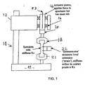
- a materials testing machine comprises a stiff frame 10 comprising a base 11 and a crosshead 12 which holds the drive assembly for an actuator 14.
- the actuator 14 comprises a piston and cylinder device which in this case is formed by a linear electric motor where the armature constitutes the piston of the actuator.
- the piston is mounted in bearings 16 and is attached to a specimen grip 18 via a load cell 20.
- a further specimen grip 21 is attached to the base 11 of the machine and the specimen to be tested is held between the grips 18 and 21.
- the position of the piston of the actuator is monitored in some suitable manner for example by an LVDT or a digital encoder 23 and the specimen is monitored in some convenient but known manner e.g. by using the load cell 20 to measure force on the specimen or by using an extensometer 22 which will measure local extension of the specimen under test.
- Such a machine is capable of conducting any one of a number of different tests on the specimen and this is achieved by means of suitable controls which drive the actuator.
- these controls are computer operated with the type of test being entered by a user into the machine using some suitable interface system such as a keypad.
- the control system and data input means are not shown in the drawing.
- the attachment of the actuator of the machine to a specimen under test having a given stiffness creates a dynamic system that can be modelled as a force that is a applied to a moving mass attached to a stiffness.
- the attachment of the moving mass to the stiffness of the specimen creates a resonant mechanical system with a certain natural frequency.
- the effect of stiffness may depend on other measurable characteristics of the system e.g. the stiffness of the oil column in a hydraulically actuated machine.
- controlling this resonance is the main challenge of the control system, since there may be very little natural damping in the system and this lack of natural damping is one of the problems associated with utilising a linear electric motor as the actuator.
- the only parameter which needs to be set by the user is the load string stiffness Ks which is defined by the change in measured load divided by the change in measured position when a load is applied to the specimen.
- the specimen stiffness Kx is a more precise value of local stiffness that is used for fine adjustment of the gains when performing strain control with an extensometer.
- the stiffness of the specimen (termed 'load string stiffness', 'Ks') is estimated automatically or entered by the user.
- the moving mass in the actuator and any other relevant stiffness/compliance is known from the machine specification, hence the natural ('resonant') frequency can be estimated.
- the 'damping factor' associated with the natural frequency is estimated from other known actuator characteristics and estimated material damping.
- Velocity feedback attempts to simulate 'viscous' damping as closely as possible, but the effect is similar to the use of the D term in a PID controller.
- the velocity signal is estimated from a digital encoder.
- the value of velocity feedback gain ('Kv') is chosen to be the largest value that achieves specified 'Phase and Gain Margins' (both well-used concepts in classical control theory), given the knowledge about the resonance and delay in the controller/actuator.
- a new modified damping factor is calculated to take account of the velocity feedback added.
- the proportional feedback gain ('Kp') for the controlled variable is calculated using knowledge of the resonance and modified damping factor. Kp is chosen to be the largest value that achieves a specified 'Phase Margin' around the resonant frequency.
- Ki integral feedback gain for the controlled variable (position, load or strain)
- Ki is chosen to be the largest value that achieves a specified 'Gain Margin' around the resonant frequency.
- Block 201 indicates the inputting of data representing the load string stiffness Ks into the machine, which as previously described may be entered manually or estimated using an additional procedure.
- the algorithm estimates the resonant frequency ⁇ and damping ⁇ of the machine system on the basis of the factory settings of the moving mass Ms of the motor and damping parameters Cm, Cb, C min K as represented by block 202.
- the velocity feedback Kv is calculated such that the highest Kv that achieves PMvel above resonance is provided. However, if resonance cannot be controlled, Kv is limited to achieve the desired gain margin at resonance.
- modified damping factor ⁇ kv is calculated in block 204 in order to include the effect of velocity feedback on the system.
- the variable feedback parameters Kp and Ki are calculated in block 205 in order to achieve the highest stable Kp that achieves the target phase margin above resonance and also the largest Ki that achieves gain margin at resonance based on the target phase and gain margins.
- the final feedback control gains Kv, Kp and Ki are set as indicated at block 210 depending on which type of test is to be undertaken by the machine.
- the system enforces a lower limit on Ki for compliant specimens and increases Kv to balance Ki so that the resonance is well controlled.
- Kp and Ki can be increased by the ratio Kx/Ks up to a maximum multiplication factor. If limited by the multiplication factor, it may be necessary to reduce Kv proportionally.
- Tdelay The delay in the feedback control loop, Tdelay, is known in advance and used in the calculations in blocks 203 and 205.
- a system designed as described has feedback control gains that are very well suited to the specimen, as long as the specimen characteristics, in particular specimen stiffness, remain the same. In reality, this cannot be guaranteed and it is necessary to detect a sudden change in specimen characteristics as soon as possible, since the feedback control gains may no longer be suitable for the changed specimen characteristics.
- One way to do this is to estimate specimen stiffness continuously, which has been done previously under the description 'adaptive control'.
- This method has the advantage of continuously updating the feedback control gains, but as implemented so far is only designed to adapt to a limited range of stiffness variation about an initial value, and requires a number of sequential measurements to calculate a new stiffness estimate, causing significant delay. This is particularly important in the current implementation using an electric linear motor, because of the highly dynamic nature of the actuator.
- This invention has instead introduced a simple but effective means for detecting a significant specimen change, based on an estimate of acceleration of the actuator.
- High actuator accelerations can occur either when the specimen stiffness decreases suddenly (for example, the specimen yields or breaks) or when it increases suddenly, and thereby causes a high frequency oscillation. If an acceleration above a preset level is detected, a special set of feedback control gains is used that has been shown to be stable for all expected specimens. The user is informed of this change, which will normally cause the test to end.
- the measure of acceleration used could be from an accelerometer fitted to the actuator. However, in this implementation it is derived from a digital encoder signal, by numerically differentiating this signal. This implementation has the advantage of a minimum of delay, since the digital encoder signal is free of the random electrical noise associated with typical accelerometer signals, and therefore does not require any further filtering.
- the present invention introduces a simple method of tuning for the user or materials testing machine based only on the stiffness of the specimen under test. This greatly simplifies the process of tuning, provides transparency to the user, and minimises the number of set-up parameters which need to be recorded.
Landscapes
- Physics & Mathematics (AREA)
- General Physics & Mathematics (AREA)
- Engineering & Computer Science (AREA)
- Health & Medical Sciences (AREA)
- Analytical Chemistry (AREA)
- General Health & Medical Sciences (AREA)
- Pathology (AREA)
- Immunology (AREA)
- Biochemistry (AREA)
- Chemical & Material Sciences (AREA)
- Life Sciences & Earth Sciences (AREA)
- Automation & Control Theory (AREA)
- Artificial Intelligence (AREA)
- Computer Vision & Pattern Recognition (AREA)
- Medical Informatics (AREA)
- Evolutionary Computation (AREA)
- Software Systems (AREA)
- Manufacturing & Machinery (AREA)
- Investigating Strength Of Materials By Application Of Mechanical Stress (AREA)
Applications Claiming Priority (3)
| Application Number | Priority Date | Filing Date | Title |
|---|---|---|---|
| GBGB0616590.6A GB0616590D0 (en) | 2006-08-21 | 2006-08-21 | Tuning of materials testing machine |
| GBGB0618211.7A GB0618211D0 (en) | 2006-08-21 | 2006-09-15 | Tuning of materials testing machine |
| PCT/IB2007/002143 WO2008023226A2 (en) | 2006-08-21 | 2007-07-26 | Adaptive control of materials testing machine with tuning of initial control parameters |
Publications (2)
| Publication Number | Publication Date |
|---|---|
| EP2047230A2 EP2047230A2 (en) | 2009-04-15 |
| EP2047230B1 true EP2047230B1 (en) | 2015-09-02 |
Family
ID=37081339
Family Applications (1)
| Application Number | Title | Priority Date | Filing Date |
|---|---|---|---|
| EP07804652.1A Active EP2047230B1 (en) | 2006-08-21 | 2007-07-26 | Automatic tuning of materials testing machine using one specimen parameter |
Country Status (7)
| Country | Link |
|---|---|
| US (1) | US8151650B2 (enExample) |
| EP (1) | EP2047230B1 (enExample) |
| JP (1) | JP5180212B2 (enExample) |
| KR (1) | KR101355016B1 (enExample) |
| CN (1) | CN101506639B (enExample) |
| GB (2) | GB0616590D0 (enExample) |
| WO (1) | WO2008023226A2 (enExample) |
Families Citing this family (21)
| Publication number | Priority date | Publication date | Assignee | Title |
|---|---|---|---|---|
| GB2467184A (en) * | 2009-01-27 | 2010-07-28 | Illinois Tool Works | Load testing apparatus |
| CN102414628A (zh) | 2009-05-01 | 2012-04-11 | 伯斯有限公司 | 具有稳定性监测的反馈控制器参数生成 |
| US9270155B2 (en) | 2012-05-20 | 2016-02-23 | Mts Systems Corporation | Linear actuator assembly |
| US9121791B2 (en) | 2012-05-21 | 2015-09-01 | Mts Systems Corporation | Head assembly for a material testing machine and method of servicing the same |
| DE102013220392B4 (de) * | 2013-10-09 | 2015-10-01 | Messphysik Materials Testing Gmbh | Materialprüfmaschine mit über eine Spindelmutter ortsfest gelagertem Spindelantrieb und Verfahren zur Einleitung einer Prüfkraft auf eine Probe |
| JP6439542B2 (ja) * | 2015-03-30 | 2018-12-19 | ブラザー工業株式会社 | 数値制御装置と制御方法 |
| CN105372119A (zh) * | 2015-12-05 | 2016-03-02 | 西安科技大学 | 能量控制下的振动致裂试验装置 |
| US10184864B2 (en) * | 2015-12-10 | 2019-01-22 | Mechanical Testing Services, Llc | Intelligent automated load control system and method |
| EP3440364B1 (en) * | 2016-04-04 | 2021-12-08 | Illinois Tool Works, Inc. | Materials testing system and method |
| EP3479091B1 (en) * | 2016-06-29 | 2023-05-03 | Illinois Tool Works Inc. | A testing system with real-time compensation of varying system parameters |
| US10545464B2 (en) * | 2016-12-01 | 2020-01-28 | The Boeing Company | Control system having variable gain feed forward (VGFF) control |
| US10416053B2 (en) * | 2017-01-23 | 2019-09-17 | Northwestern University | Grips for a linear fracture testing machine and method of designing same |
| JP6420388B2 (ja) * | 2017-03-13 | 2018-11-07 | ファナック株式会社 | サーボモータ制御装置、及び、サーボモータ制御システム |
| CN107577142A (zh) * | 2017-07-31 | 2018-01-12 | 中国建筑股份有限公司 | 一种大刚度结构试验加载方法 |
| CN108414346B (zh) * | 2018-03-28 | 2019-08-27 | 东北大学 | 一种试验参数自适应的智能真三轴试验系统及试验方法 |
| US10724931B2 (en) * | 2018-10-15 | 2020-07-28 | Illinois Tool Works Inc. | Outer loop torque control |
| US10829332B2 (en) * | 2018-11-21 | 2020-11-10 | Illinois Tool Works Inc. | Specimen clearing apparatus |
| US11726018B2 (en) | 2018-11-30 | 2023-08-15 | Illinois Tool Works Inc. | Safety system interfaces and material testing systems including safety system interfaces |
| JP7234733B2 (ja) * | 2019-03-27 | 2023-03-08 | 株式会社島津製作所 | 制御装置、材料試験機、制御装置の制御方法、及び制御プログラム |
| GB2599448A (en) * | 2020-10-05 | 2022-04-06 | Illinois Tool Works | Material testing system |
| GB202017212D0 (en) * | 2020-10-30 | 2020-12-16 | Illinois Tool Works | Apparatus and method for material testing |
Citations (1)
| Publication number | Priority date | Publication date | Assignee | Title |
|---|---|---|---|---|
| US5511431A (en) * | 1993-09-24 | 1996-04-30 | Instron Limited | Structure testing machine |
Family Cites Families (14)
| Publication number | Priority date | Publication date | Assignee | Title |
|---|---|---|---|---|
| US4537077A (en) * | 1984-02-08 | 1985-08-27 | Mts Systems Corporation | Load dynamics compensation circuit for servohydraulic control systems |
| US4802367A (en) * | 1986-12-09 | 1989-02-07 | Mts Systems Corporation | Tensile test controller |
| US5090249A (en) * | 1990-08-08 | 1992-02-25 | Jerzy Bielewicz | Apparatus and method for testing the mechanical properties of a sample |
| JPH07107766A (ja) * | 1993-10-01 | 1995-04-21 | Matsushita Electric Ind Co Ltd | サーボゲインパラメータチューニング装置 |
| US5684374A (en) * | 1995-07-27 | 1997-11-04 | Allen-Bradley Company, Inc. | Method and apparatus for tuning a motion control system having an external velocity loop |
| JP3340055B2 (ja) * | 1997-08-13 | 2002-10-28 | 日本たばこ産業株式会社 | 材料試験機 |
| EP0897110A3 (en) | 1997-08-13 | 2000-01-12 | Japan Tobacco Inc. | Material testing machine |
| JP3340054B2 (ja) * | 1997-08-13 | 2002-10-28 | 日本たばこ産業株式会社 | 材料試験機 |
| JP3368182B2 (ja) * | 1997-08-13 | 2003-01-20 | 日本たばこ産業株式会社 | 材料試験機 |
| JP3819620B2 (ja) * | 1998-12-04 | 2006-09-13 | 株式会社鷺宮製作所 | 材料試験機用制御装置 |
| JP2000298083A (ja) * | 1999-04-14 | 2000-10-24 | Saginomiya Seisakusho Inc | 材料試験機およびその停止方法 |
| JP4218201B2 (ja) * | 2000-09-29 | 2009-02-04 | 株式会社島津製作所 | 材料試験装置 |
| DE60032909T2 (de) * | 2000-11-16 | 2007-10-25 | Stmicroelectronics S.R.L., Agrate Brianza | Automatische Eichung eines mikromechanischen Sensors |
| JP3852072B2 (ja) * | 2001-09-28 | 2006-11-29 | 株式会社島津製作所 | 油圧サーボ式材料試験機 |
-
2006
- 2006-08-21 GB GBGB0616590.6A patent/GB0616590D0/en active Pending
- 2006-09-15 GB GBGB0618211.7A patent/GB0618211D0/en not_active Ceased
-
2007
- 2007-07-26 WO PCT/IB2007/002143 patent/WO2008023226A2/en not_active Ceased
- 2007-07-26 US US12/376,742 patent/US8151650B2/en active Active
- 2007-07-26 JP JP2009525117A patent/JP5180212B2/ja active Active
- 2007-07-26 EP EP07804652.1A patent/EP2047230B1/en active Active
- 2007-07-26 KR KR1020097003393A patent/KR101355016B1/ko active Active
- 2007-07-26 CN CN2007800309263A patent/CN101506639B/zh active Active
Patent Citations (1)
| Publication number | Priority date | Publication date | Assignee | Title |
|---|---|---|---|---|
| US5511431A (en) * | 1993-09-24 | 1996-04-30 | Instron Limited | Structure testing machine |
Also Published As
| Publication number | Publication date |
|---|---|
| GB0618211D0 (en) | 2006-10-25 |
| KR101355016B1 (ko) | 2014-02-04 |
| CN101506639B (zh) | 2013-04-10 |
| US8151650B2 (en) | 2012-04-10 |
| WO2008023226A2 (en) | 2008-02-28 |
| WO2008023226A3 (en) | 2008-06-12 |
| JP2010501846A (ja) | 2010-01-21 |
| EP2047230A2 (en) | 2009-04-15 |
| CN101506639A (zh) | 2009-08-12 |
| KR20090053784A (ko) | 2009-05-27 |
| US20100229652A1 (en) | 2010-09-16 |
| JP5180212B2 (ja) | 2013-04-10 |
| GB0616590D0 (en) | 2006-09-27 |
Similar Documents
| Publication | Publication Date | Title |
|---|---|---|
| EP2047230B1 (en) | Automatic tuning of materials testing machine using one specimen parameter | |
| JP5670918B2 (ja) | 電磁アクチュエータの適応制御のための装置、制御器、及び方法 | |
| US8138693B2 (en) | Vibration isolation control system | |
| JP5452720B2 (ja) | モータ制御装置 | |
| CN108398920B (zh) | 伺服控制装置 | |
| EP1821168B1 (en) | Controller for servomotor | |
| JP2013126266A (ja) | サーボ制御装置およびその調整方法 | |
| JPWO2009019953A1 (ja) | 電動機制御装置およびそのゲイン調整方法 | |
| JP4973665B2 (ja) | 電動機制御装置と出力フィルタ調整方法および出力フィルタ調整装置 | |
| JP2020181424A (ja) | 数値制御装置及び工作機械 | |
| JP3852072B2 (ja) | 油圧サーボ式材料試験機 | |
| JPH07319506A (ja) | オートチューニングコントローラ | |
| JP2932235B2 (ja) | 連続鋳造機のモールドオッシレーション装置 | |
| JP2003106967A (ja) | 油圧−サーボ式材料試験機 | |
| JP2024170591A (ja) | 外部ループトルク制御 | |
| CN112305996A (zh) | 数值控制装置和控制方法 | |
| JP7132024B2 (ja) | モータ制御装置 | |
| O’hagan et al. | Experimental assessment of PID control for a uniaxial shake table | |
| CN116893613A (zh) | 伺服控制设备和伺服控制方法 | |
| JP3026174B2 (ja) | モールドオシレーション制御装置 | |
| JP2006198742A (ja) | 穴明け加工機 | |
| JP2000056837A (ja) | ステージ位置制御系のpid調整方法およびステージ速度制御系のpi調整方法ならびにステージ装置 | |
| CN121277122A (zh) | 一种基于闭环控制的大型机床结构件振动时效工艺优化系统、方法及设备 |
Legal Events
| Date | Code | Title | Description |
|---|---|---|---|
| PUAI | Public reference made under article 153(3) epc to a published international application that has entered the european phase |
Free format text: ORIGINAL CODE: 0009012 |
|
| 17P | Request for examination filed |
Effective date: 20090219 |
|
| AK | Designated contracting states |
Kind code of ref document: A2 Designated state(s): AT BE BG CH CY CZ DE DK EE ES FI FR GB GR HU IE IS IT LI LT LU LV MC MT NL PL PT RO SE SI SK TR |
|
| AX | Request for extension of the european patent |
Extension state: AL BA HR MK RS |
|
| RBV | Designated contracting states (corrected) |
Designated state(s): DE FR GB |
|
| DAX | Request for extension of the european patent (deleted) | ||
| 17Q | First examination report despatched |
Effective date: 20101004 |
|
| RAP1 | Party data changed (applicant data changed or rights of an application transferred) |
Owner name: ILLINOIS TOOL WORKS INC. |
|
| REG | Reference to a national code |
Ref country code: DE Ref legal event code: R079 Ref document number: 602007042918 Country of ref document: DE Free format text: PREVIOUS MAIN CLASS: G01N0003020000 Ipc: G01N0003080000 |
|
| GRAP | Despatch of communication of intention to grant a patent |
Free format text: ORIGINAL CODE: EPIDOSNIGR1 |
|
| RIC1 | Information provided on ipc code assigned before grant |
Ipc: G01N 3/08 20060101AFI20150318BHEP |
|
| INTG | Intention to grant announced |
Effective date: 20150409 |
|
| RIN1 | Information on inventor provided before grant (corrected) |
Inventor name: JEPPESEN, BEN Inventor name: HAYFORD, PAUL |
|
| GRAS | Grant fee paid |
Free format text: ORIGINAL CODE: EPIDOSNIGR3 |
|
| GRAA | (expected) grant |
Free format text: ORIGINAL CODE: 0009210 |
|
| AK | Designated contracting states |
Kind code of ref document: B1 Designated state(s): DE FR GB |
|
| REG | Reference to a national code |
Ref country code: GB Ref legal event code: FG4D |
|
| REG | Reference to a national code |
Ref country code: DE Ref legal event code: R096 Ref document number: 602007042918 Country of ref document: DE |
|
| REG | Reference to a national code |
Ref country code: DE Ref legal event code: R097 Ref document number: 602007042918 Country of ref document: DE |
|
| PLBE | No opposition filed within time limit |
Free format text: ORIGINAL CODE: 0009261 |
|
| STAA | Information on the status of an ep patent application or granted ep patent |
Free format text: STATUS: NO OPPOSITION FILED WITHIN TIME LIMIT |
|
| REG | Reference to a national code |
Ref country code: FR Ref legal event code: PLFP Year of fee payment: 10 |
|
| 26N | No opposition filed |
Effective date: 20160603 |
|
| REG | Reference to a national code |
Ref country code: FR Ref legal event code: PLFP Year of fee payment: 11 |
|
| REG | Reference to a national code |
Ref country code: FR Ref legal event code: PLFP Year of fee payment: 12 |
|
| P01 | Opt-out of the competence of the unified patent court (upc) registered |
Effective date: 20230606 |
|
| PGFP | Annual fee paid to national office [announced via postgrant information from national office to epo] |
Ref country code: DE Payment date: 20250729 Year of fee payment: 19 |
|
| PGFP | Annual fee paid to national office [announced via postgrant information from national office to epo] |
Ref country code: GB Payment date: 20250728 Year of fee payment: 19 |
|
| PGFP | Annual fee paid to national office [announced via postgrant information from national office to epo] |
Ref country code: FR Payment date: 20250728 Year of fee payment: 19 |