EP2047151B1 - Quetschventil - Google Patents
Quetschventil Download PDFInfo
- Publication number
- EP2047151B1 EP2047151B1 EP07847032A EP07847032A EP2047151B1 EP 2047151 B1 EP2047151 B1 EP 2047151B1 EP 07847032 A EP07847032 A EP 07847032A EP 07847032 A EP07847032 A EP 07847032A EP 2047151 B1 EP2047151 B1 EP 2047151B1
- Authority
- EP
- European Patent Office
- Prior art keywords
- valve member
- support tube
- shell elements
- circumferential wall
- valve
- Prior art date
- Legal status (The legal status is an assumption and is not a legal conclusion. Google has not performed a legal analysis and makes no representation as to the accuracy of the status listed.)
- Active
Links
- 239000012530 fluid Substances 0.000 claims abstract description 27
- 238000009434 installation Methods 0.000 claims 1
- 230000036316 preload Effects 0.000 claims 1
- 230000002093 peripheral effect Effects 0.000 description 36
- 230000008901 benefit Effects 0.000 description 4
- 238000003780 insertion Methods 0.000 description 3
- 230000037431 insertion Effects 0.000 description 3
- 230000000295 complement effect Effects 0.000 description 2
- 238000002788 crimping Methods 0.000 description 2
- 230000001747 exhibiting effect Effects 0.000 description 2
- 210000004072 lung Anatomy 0.000 description 2
- 239000000463 material Substances 0.000 description 2
- 238000005192 partition Methods 0.000 description 2
- 101100289200 Caenorhabditis elegans lite-1 gene Proteins 0.000 description 1
- 230000006978 adaptation Effects 0.000 description 1
- 238000004026 adhesive bonding Methods 0.000 description 1
- 238000004891 communication Methods 0.000 description 1
- 239000002131 composite material Substances 0.000 description 1
- 238000010276 construction Methods 0.000 description 1
- 230000001419 dependent effect Effects 0.000 description 1
- 238000011161 development Methods 0.000 description 1
- 230000018109 developmental process Effects 0.000 description 1
- 238000000605 extraction Methods 0.000 description 1
- 230000009969 flowable effect Effects 0.000 description 1
- 239000007789 gas Substances 0.000 description 1
- 238000004519 manufacturing process Methods 0.000 description 1
- 230000007935 neutral effect Effects 0.000 description 1
- 238000007789 sealing Methods 0.000 description 1
- 230000011218 segmentation Effects 0.000 description 1
- 238000000926 separation method Methods 0.000 description 1
- 238000003466 welding Methods 0.000 description 1
Images


Classifications
-
- F—MECHANICAL ENGINEERING; LIGHTING; HEATING; WEAPONS; BLASTING
- F16—ENGINEERING ELEMENTS AND UNITS; GENERAL MEASURES FOR PRODUCING AND MAINTAINING EFFECTIVE FUNCTIONING OF MACHINES OR INSTALLATIONS; THERMAL INSULATION IN GENERAL
- F16K—VALVES; TAPS; COCKS; ACTUATING-FLOATS; DEVICES FOR VENTING OR AERATING
- F16K7/00—Diaphragm valves or cut-off apparatus, e.g. with a member deformed, but not moved bodily, to close the passage ; Pinch valves
- F16K7/02—Diaphragm valves or cut-off apparatus, e.g. with a member deformed, but not moved bodily, to close the passage ; Pinch valves with tubular diaphragm
- F16K7/04—Diaphragm valves or cut-off apparatus, e.g. with a member deformed, but not moved bodily, to close the passage ; Pinch valves with tubular diaphragm constrictable by external radial force
- F16K7/06—Diaphragm valves or cut-off apparatus, e.g. with a member deformed, but not moved bodily, to close the passage ; Pinch valves with tubular diaphragm constrictable by external radial force by means of a screw-spindle, cam, or other mechanical means
- F16K7/065—Cam clamps
-
- F—MECHANICAL ENGINEERING; LIGHTING; HEATING; WEAPONS; BLASTING
- F16—ENGINEERING ELEMENTS AND UNITS; GENERAL MEASURES FOR PRODUCING AND MAINTAINING EFFECTIVE FUNCTIONING OF MACHINES OR INSTALLATIONS; THERMAL INSULATION IN GENERAL
- F16K—VALVES; TAPS; COCKS; ACTUATING-FLOATS; DEVICES FOR VENTING OR AERATING
- F16K7/00—Diaphragm valves or cut-off apparatus, e.g. with a member deformed, but not moved bodily, to close the passage ; Pinch valves
- F16K7/02—Diaphragm valves or cut-off apparatus, e.g. with a member deformed, but not moved bodily, to close the passage ; Pinch valves with tubular diaphragm
- F16K7/04—Diaphragm valves or cut-off apparatus, e.g. with a member deformed, but not moved bodily, to close the passage ; Pinch valves with tubular diaphragm constrictable by external radial force
- F16K7/07—Diaphragm valves or cut-off apparatus, e.g. with a member deformed, but not moved bodily, to close the passage ; Pinch valves with tubular diaphragm constrictable by external radial force by means of fluid pressure
Definitions
- the invention relates to a pinch valve, comprising a valve housing in which extends between two fluid ports, a flexible circumferential wall exhibiting tubular valve member, the peripheral wall is transverse to the valve member longitudinal axis fauxquetschbar to change the flow area, and of a radial expansion limiting its rigid Support tube is enclosed, with which it is assembled to a removably inserted axially into the valve housing cartridge-like assembly and which consists of several in the circumferential direction of the peripheral wall of the valve member around the peripheral wall lined up around, each having an arcuate cross-section having shell elements in relation to the Valve member longitudinal axis radial direction are attached externally to the tubular valve member, wherein on the shell elements and on the valve member form-fitting interlocking position-specifying means are arranged, which the in the circumferential direction with respect to the valve member assumed circumferential position of the shell elements pretend, and wherein the valve member has at its two ends in each case a radially projecting flange portion, wherein the support tube
- a pinch valve which is designed as part of a dental instrument.
- a handle body of the instrument acts as a valve housing, in which a tubular valve member is used, which communicates with the front side, each with a fluid connection.
- the valve member can be traversed by a fluid, wherein the flow cross-section can be changed by a pinch means designed as a ball, through which the flexible peripheral wall of the valve member can be squeezed more or less far.
- the valve member is formed together with a circumferential wall coaxially surrounding support tube as a detachably inserted into the valve housing cartridge-like assembly. This unit can be easily replaced if necessary.
- support tube also connected problems in handling. It is relatively cumbersome to use the usually not very rigid valve member in the support tube.
- a hose-check valve in which a tubular valve member is mounted on an insert body and outside of the valve member a longitudinally split shell body is placed.
- the valve housing is radially divided and is pushed axially during assembly with its two parts from opposite sides to the shell body containing unit. To replace the valve member, the valve body must therefore be completely disassembled.
- the tubular valve member is disposed in the inner bore of a one-piece housing and radially supported by this. Through the wall of this housing pass channels that allow the passage of a valve member to be compressed fluid when a sleeve disposed around the housing is axially displaced.
- An Indian GB 1 021 540 explained flow valve includes a flow channel dividing partition, on which a valve member acting as a hose is clamped. Depending on the fluid pressure in a chamber surrounding the hose, the hose can lift off from the partition to release a flow cross-section.
- the chamber is bounded radially on the outside by a sleeve, on which the hose can be supported.
- pinch valves are known in which as cooperating with the valve member crushing no objective crushing as in the case of DE 29 30 853 C2 is used, but a fluidic pressure medium, such as compressed air.
- a pinch valve is derived, for example, from the undated product information "Pneumatic pinch valve type VMF / Pneumatic pinch valve type VMF" from Armaturen & Separations GmbH.
- There are no means for limiting the radial expansion of the valve member are provided on the valve housing addition. The tubular valve member is therefore subject to greater stresses than in the case of its additional radial support.
- a pinch valve of the aforementioned type is known, the tubular valve member is enclosed by a housing-like frame, which is divided axially into two half-frame body, which are attached from radially outside to the valve member.
- the DE 10 24 300 B describes a tube valve with a housing having a cylindrical longitudinal bore in which a piece of tubing acting as a valve member is received. A pressure medium can pass through through openings pressed on the outside of the hose body to reduce this in its diameter.
- An essential object of the present invention is to provide a pinch valve, the valve member is easy to install without affecting its support.
- the position presetting means comprise, on the one hand, recesses and projections arranged in a form-fitting manner on the flange sections of the valve member and, on the other hand, on the shell elements of the support tube.
- the individual shell elements of the support tube can be attached from the radially outside to the tubular valve member, thus forming the, in its circumferential direction segmented, support tube.
- the pipe channel of the support tube and / or the peripheral wall of the valve member have a non-circular cross-sectional contour
- the support tube has only two shell elements, which then preferably have an arc extent of 180 °. These are in particular identical components, so that a cost-saving production is possible.
- An elongated cross-sectional shape of the peripheral wall of the valve member has the advantage that, in the external fluid loading of the peripheral wall, a squeezing takes place in a preferred direction, transverse to the cross-sectional longitudinal axis. As a result, the flow cross-section can be shut off very reliably.
- the shell elements in the axial direction an excess with respect to the clear distance between two end-Von It is advantageous if the shell elements in the axial direction have an excess with respect to the clear distance between two end-side flange portions of the flexible valve member.
- Characterized the circumferential wall of the valve member is axially stretched when assembling the cartridge-like assembly, which has a radially outwardly biased bias of the peripheral wall result, so that the expansion of the peripheral wall is supported, if currently no squeezing forces are exerted on the peripheral wall from the outside.
- One, several or all shell elements may have at least one radial opening, through which the peripheral wall can be acted upon by a squeezing agent in order to produce the squeezing of the peripheral wall required for the variation of the flow cross section.
- a squeezing agent in order to produce the squeezing of the peripheral wall required for the variation of the flow cross section.
- the pressure medium is in particular compressed air, but other gases as well as a pressure fluid are also conceivable.
- a securing body enclosing the segmented support tube is expediently provided. It is preferably a component that is separate relative to the valve housing and that may also be a component of the cartridge-type structural unit.
- an embodiment as the support tube coaxially enclosing securing tube which can be easily plugged after the shell elements were attached to the valve member.
- the securing body may, like the support tube, have at least one radial opening for a squeezing means acting on the peripheral wall of the valve member.
- the two pinch valves designated in their entirety by reference numeral 1 contain a valve housing 2, which surrounds a receiving space 3.
- the valve housing 2 comprises a tubular housing main part 4, on whose two end faces a respective connecting piece 5, 6 acquiring a cover function is arranged.
- At least one and expediently both connecting pieces 5, 6 are relative to the housing main part 4 separate components and detachably attached to the housing main body 4. By way of example, they are each screwed into the housing main part 4 at the front.
- the cooperating with each other inner and outer threads are indicated at 7.
- connection piece 5, 6 is equipped with a fluid connection 8, which is formed by an axial through-passage.
- connection means 12, for example, internal thread, allow the connection not shown in detail fluid lines, through which a through the pinch valve 1 to controlling, hereinafter referred to simply as "fluid" designated flowable medium and can be discharged.
- valve member 14 At its two ends, following the peripheral wall 13, the valve member 14 each has a radially projecting, preferably annular flange 16. It expediently consists of the same material as the peripheral wall 13.
- the tubular valve member 14 is a one-piece element.
- the flange portions 16 are located around the mouth of the respective associated fluid port 8, with sealing at the two connecting pieces 5, 6 at. This results in a consistently sealed connection.
- a fluid to be controlled can be fed, which passes through the control channel 15 to the respective other fluid port 8 and leaves the pinch valve 1 again via this.
- the peripheral wall 13 can be more or less squeezed together to change the provided by the control channel 15 flow cross section. If no squeezing force is applied, it is off FIGS. 1 . 3 . 6 and 8th apparent maximum opening in which the fluid is the maximum flow area available.
- the valve member 14 is preferably a rubber-elastic molded part whose circumferential wall 13 in the non-radially applied initial state, solely due to its inherent dimensional stability, has a shape tapering axially from its outside towards its longitudinal central region. This is off FIGS. 1 and 6 good to see.
- FIGS. 1 and 6 good to see.
- the cross section of the peripheral wall 13 is that this is suitably elongated, which is well based on Figures 3 and 8th understand.
- the circumferential wall 13 of the tubular valve member 14 is acted upon by the pressure medium flowing in the control channel 15 in the sense of a radial expansion.
- a rigid support tube 18 coaxially enclosing the valve member 14 at least in the region of the circumferential wall 13 prevents overstretching of the flexible material and, in particular, predetermines the outer contour occupied by the peripheral wall 13 in the maximum open position.
- the interior of the support tube 18, referred to as tube channel 22, is coaxially penetrated by the valve member 14, wherein its inner surface forms a support surface 23 for the peripheral wall 13.
- the tube channel 22 is designed such that its inner contour corresponds to the outer contour of the circumferential wall 13 present in the unloaded initial state. This has the consequence that the peripheral wall 13 at Fluid supply to the control channel 15 is not radially expanded beyond its initial state addition. Thus, the peripheral wall is always deformed starting from the neutral position only to a radial side, which benefits the life.
- the tube channel 22 expediently also has an elongate cross-sectional shape.
- the mutual cross-sectional longitudinal axes 21 coincide expediently.
- the support tube 18 is not a one-piece, but a segmented in its circumferential direction tubular body. It consists of several in the direction indicated by a double arrow 24 circumferential direction of the peripheral wall 13 lined up around them, according to arrows 25 from radially outside to the outer periphery of the valve member 14 scheduled shell elements 26, 27 together.
- the latter each have an arcuate cross section, so that they define the tube structure of the support tube in the assembled state.
- the composite support tube 18 is designed substantially circular cylindrical.
- a respective securing body 28a, 28b which is configured differently in the two exemplary embodiments.
- This can for example consist of one or more ring elements.
- the securing body 28a, 28b is tubular, wherein it surrounds the segmented in its circumferential direction support tube 18 coaxially.
- the function of the fuse body 28a, 28b could be taken over directly by the housing main part 4. However, it is preferable, particularly with a view to easy handling, to adopt a construction in which the securing body 28a, 28b is a separate component with respect to the valve housing 2, which component can be detachably inserted into the receiving space 3.
- the securing body 28a, 28b acts like a clamp or cuff, which prevents the shell elements 26, 27 from being pushed outward by the fluid pressure prevailing in the control channel 15.
- the pressure forces introduced by the fluid via the peripheral wall 13 into the shell elements 26, 27 are therefore absorbed by the preferably tubular securing body 28a, 28b.
- the valve housing 2 is not loaded as a result.
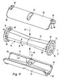
- a particular advantage of the pinch valve is due to the fact that the valve member 14, the segmented support tube 18 and the respectively used fuse body 28a, 28b to a in Figures 5 and 10 individually illustrated cartridge-like assembly 32a, 32b are summarized.
- This assembly 32a, 32b is used in its entirety in a removable manner axially into the receiving space 3 of the valve housing 2.
- the outer contour of the cartridge-like structural unit 32a, 32b is in this case matched to the inner contour of the receiving space 3 defined by the housing main part 4 such that the axial insertion and removal can be carried out by a simple insertion and extraction operation.
- the securing body 28b is radially stepped on the outside and contains a pipe section 33 which occupies the greater part of its length and adjoins at one end a piston section 34 having a larger diameter.
- the securing body 28b is supported in the assembled state only via its piston portion 34 directly on the peripheral wall of the receiving space 3.
- the pipe section 33 and the wall of the housing main part 4 remains a concentric annular space 35, the function will be explained.
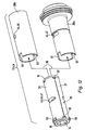
- the assembly of the cartridge-like assembly 32 a, 32 b is most easily done by first according to FIG. 11 the shell elements 26, 27 attached to the valve member 14 and then this preassembled unit is inserted into the selected fuse body 28 a or 28 b, as shown in FIG. 12 indicated by the arrows 36.
- the cartridge-like assembly 32a, 32b expediently clamped axially between the two connecting pieces 5, 6. These press on the outer end face 37 of the adjacent flange section 16 facing them, which in turn is supported with its axially oppositely oriented inner axial end face 38 on the end face of the segmented support tube 18 extending between the flange sections 16.
- the length measured in the direction of the valve member longitudinal axis 17 is the Shell elements 26, 27 chosen so that they can be used in the axial gap defined between the two end side flange portions 16 in the region of the outer circumference of the peripheral wall 13.
- the support tube 18 is thus flanked by the front end of the two flange portions 16.
- the shell elements 26, 27 are slightly longer than the existing before mounting on the valve member 14 between the two flange portions 16 clear axial distance. This results in that the flange portions 16 are slightly pushed away from each other by the attached support tube 18, resulting in an axial tension bias of the peripheral wall 13 results. This in turn has the consequence that the peripheral wall 13 is acted upon in the direction of the maximum open position radially outward even in the unpressurized state of the control channel 15. This favors the assumption of the maximum open position when no squeezing means act on the peripheral wall 13.
- the cartridge-like assembly 32b due to their symmetrical structure selectively removed via the one or the other axial end face of the housing main body 4 and reused.
- the assembly and disassembly preferably takes place via that end face of the housing main part 4, in the region of which the piston section 34 comes to lie.
- An undercut recess 42 which is formed in the area of the piston section 34 in the securing body 28a, is made possible when the connecting piece is removed 6 a simple gripping with a tool or by hand to pull out the entire assembly 32 a.
- the support tube 18 could be realized by more than two shell elements 26, 27, the variant of the embodiment is recommended in which the support tube 18 of only two shell elements 26, 27 composed, each having an arc extent of 180 ° in the circumferential direction 24 , One can speak of two half-shells here.
- one or more squeezing means 19 can act freely on the outer periphery of the peripheral wall 13, the wall of the support tube 18 and the wall of the fuse body 28 a, 28 b of at least one opening 43, 44 radially interspersed, which are aligned with each other so that the or Crimping 19 can pass.
- Each shell element 26, 27 preferably contains an opening 43, which is aligned with a radially opposite opening 44 of the securing body 28a, 28b enclosing it.
- the number of aligned openings 43, 44 is arbitrary. It could also be only one fürbrechungsfar 43, 44 are present, as well as in principle more than two such aperture pairs 43, 44 would be feasible.
- the squeezing means consists of a pressure medium which can be fed into the receiving space 3 via an actuating channel 45 passing through the valve housing 2.
- the openings 43, 44 each as a fluid channel 46, through which the pressure medium used for the actuation can flow into the tube channel 22 to pressurize the peripheral wall 13 with a fluidic clamping force.
- the openings 43, 44 act as passage openings 47, in each of which a respective squeezing element 48 serving as squeezing means 19 is mounted so as to be radially displaceable in accordance with the double arrow 52.
- These squeeze elements can mechanically act on the peripheral wall 13 to exert the required squeezing force.
- the radial actuating force for actuating the squeezing elements 48 preferably provides an annular loading device 53, which is arranged in the above-mentioned annular space 35 coaxially around the inserted cartridge-like assembly 32a in an axially movable manner.
- the pipe section 33 in this case forms a guide element for an axially displaceable mounting of the loading device 53.
- oblique Beauftschungs vom 54 engage over the squeezing 48 radially outward and press them depending on the axial position of the loading device 53 more or less radially inward.
- a machanic spring device 55 likewise arranged in the annular space 35, constantly acts in a pertinent sense on the loading device 53 in that it pretensions the squeezing elements 48 in the direction of the closed position.
- This pinch valve is of the "normally closed” type and assumes the closed position as long as no actuation signal is present.
- a fluidic pressure medium is fed into an actuating chamber 57 in the embodiment via a valve housing 2 passing through the actuating channel 56, which by the loading device 53 within of the annular space 35 is divided off fluid-tight.
- the actuating fluid supplied to the actuating chamber 57 with sufficiently high pressure can displace the loading device 53 counter to the spring force, so that the squeezing elements 48 can move radially outward in order to release the control channel 15.
- the force overcoming the spring force could also be applied in other ways than by a fluidic force, for example electrically or manually.
- the pinch valve is the FIGS. 6 to 10 of type "normally open".
- the maximum flow cross section of the control channel 15 is present when no pressure medium is fed via the actuation channel 45 and thus no actuation signal is present.
- the squeezing elements 48 and an actuating piston 58 of the loading device 53 that can be acted upon by the actuating fluid 57 located in the actuating chamber 57 can be components of the cartridge-type structural unit 32a, 32b.
- the fuse bodies 28a, 28b as components which always remain in the valve housing 2 and thus do not belong to the cartridge-type structural unit 32a, 32b.
- the cartridge-like assembly 32a, 32b would consist solely of the valve member 14 and the shell elements 26, 27. This also applies if a securing body 28a, 28b is completely dispensed with.
- the shell members 26, 27 are detachably attached to the valve member 14 to attach, they could for example also be cohesively connected to each other, for example by gluing or welding.
- position setting means 62 should be present, which dictate the mounting position and also ensure later.
- position setting means 62 are formed, on the one hand, on the shell elements 26, 27 and, on the other hand, on the valve member 14 in such a way that they intermesh positively when the desired relative position is taken. As a result, in particular an anti-rotation in the circumferential direction of the valve member longitudinal axis 17 is achieved.
- position setting means 62 designed as end-side recesses are formed on the end faces of the shell elements 26, 27, while complementary projection-like position specification means 62 are formed on the mutually facing inner end faces 38 of the flange sections 16.
- the positive engagement occurs when applying the shell elements 26, 27, wherein the assembly is favored by the rubber elasticity of the valve member 14.
- further position-setting means 63 which engage in one another in a form-fitting manner are therefore also formed on the securing bodies 28a, 28b and on the shell elements 26, 27.
- these are at an end portion of the shell elements 26, 27 of these radially protruding projections which engage positively in frontal recesses of the fuse body 28a, 28b, when the components are plugged together.
- the cartridge-like installable assembly 32a, 32b facilitates and accelerates a possible replacement of a worn valve member 14. If the shell elements 26, 27 releasably connected to each other, they can be used again, and the exchange is limited to the valve member 14 as such. However, it is also considered particularly useful to provide at least the assembly consisting of valve member 14 and shell elements 26, 27 as a total interchangeable unit, as this allows a rapid replacement without loss of time.
Description
- Die Erfindung betrifft ein Quetschventil, mit einem Ventilgehäuse, in dem sich zwischen zwei Fluidanschlüssen ein eine flexible Umfangswand aufweisendes schlauchförmiges Ventilglied erstreckt, dessen Umfangswand quer zur Ventilglied-Längsachse zusammenquetschbar ist, um den Durchflussquerschnitt zu verändern, und das von einem seine radiale Aufweitung begrenzenden starren Stützrohr umschlossen ist, mit dem es zu einer in entnehmbarer Weise axial in das Ventilgehäuse eingesetzten patronenartigen Baueinheit zusammengesetzt ist und das aus mehreren in der Umfangsrichtung der Umfangswand des Ventilgliedes um die Umfangswand herum aneinandergereihten, jeweils einen bogenförmigen Querschnitt aufweisenden Schalenelementen besteht, die in bezüglich der Ventilglied-Längsachse radialer Richtung außen an das schlauchförmige Ventilglied angesetzt sind, wobei an den Schalenelementen und an dem Ventilglied formschlüssig ineinandergreifende Positionsvorgabemittel angeordnet sind, die die in der Umfangsrichtung bezüglich des Ventilgliedes eingenommene Umfangsposition der Schalenelemente vorgeben, und wobei das Ventilglied an seinen beiden Enden jeweils einen radial abstehenden Flanschabschnitt aufweist, wobei das Stützrohr axial zwischen diesen beiden Flanschabschnitten angeordnet ist und stirnseitig von diesen flankiert wird.
- Aus der
DE 29 30 853 C2 ist ein Quetschventil bekannt, das als Bestandteil eines zahnärztlichen Instrumentes ausgeführt ist. Ein Griffkörper des Instrumentes fungiert als Ventilgehäuse, in das ein schlauchförmiges Ventilglied eingesetzt ist, das stirnseitig mit je einem Fluidanschluss kommuniziert. Das Ventilglied kann von einem Fluid durchströmt werden, wobei sich der Durchflussquerschnitt durch ein als Kugel ausgebildetes Quetschmittel verändern lässt, durch das die flexible Umfangswand des Ventilgliedes mehr oder weniger weit zusammengequetscht werden kann. Das Ventilglied ist gemeinsam mit einem seine Umfangswand koaxial umschließenden Stützrohr als lösbar in das Ventilgehäuse eingesetzte patronenartige Baueinheit ausgebildet. Diese Baueinheit kann bei Bedarf leicht ausgewechselt werden. Allerdings sind mit dem gemäßDE 29 30 853 C2 vorgesehenen Stützrohr auch Probleme in der Handhabung verbunden. Es ist relativ umständlich, das in der Regel nicht sehr biegesteife Ventilglied in das Stützrohr einzusetzen. - Aus der
DE 10 50 622 C geht ein Schlauch-Absperrventil hervor, bei dem ein schlauchförmiges Ventilglied auf einem Einsatzkörper montiert ist und außen auf das Ventilglied ein in Längsrichtung geteilter Schalenkörper aufgesetzt ist. Das Ventilgehäuse ist radial geteilt und wird beim Zusammenbau mit seinen beiden Teilen von entgegengesetzten Seiten her axial auf die den Schalenkörper enthaltende Einheit geschoben. Zum Auswechseln des Ventilgliedes muss das Ventilgehäuse folglich komplett zerlegt werden. - Bei einem aus der
DE 10 24 300 B bekannten Schlauchventil ist das schlauchförmige Ventilglied in der Innenbohrung eines einstückigen Gehäuses angeordnet und von diesem radial abgestützt. Durch die Wandung dieses Gehäuses führen Kanäle, die den Durchtritt eines das Ventilglied zusammenquetschenden Fluides ermöglichen, wenn eine um das Gehäuse herum angeordnete Hülse axial verstellt wird. - Ein in der
GB 1 021 540 - Es sind auch bereits Quetschventile bekannt, bei denen als mit dem Ventilglied zusammenwirkendes Quetschmittel kein gegenständliches Quetschelement wie im Falle der
DE 29 30 853 C2 eingesetzt wird, sondern ein fluidisches Druckmedium, beispielsweise Druckluft. Ein solches Quetschventil geht beispielsweise aus der nicht datierten Produktinformation "Pneumatisches Quetschventil Typ VMF/Pneumatic pinch valve type VMF" der Firma Armaturen & Separations GmbH hervor. Dort sind über das Ventilgehäuse hinaus keine Mittel zur Begrenzung der radialen Aufweitung des Ventilgliedes vorgesehen. Das schlauchförmige Ventilglied unterliegt daher stärkeren Beanspruchungen als im Falle seiner zusätzlichen radialen Abstützung. - Aus der
JP 62-278382 A - Die
DE 10 24 300 B beschreibt ein Schlauchventil mit einem Gehäuse, das eine zylindrische Längsbohrung aufweist, in der ein als Ventilglied fungierendes Schlauchstück aufgenommen ist. Ein Druckmittel kann durch Durchtrittsöffnungen hindurch auf die Außenseite des Schlauchkörpers gepresst werden, um dieses in seinem Durchmesser zu verkleinern. - Eine wesentliche Aufgabe der vorliegenden Erfindung besteht darin, ein Quetschventil zu schaffen, dessen Ventilglied ohne Beeinträchtigung seiner Abstützung einfach installierbar ist.
- Zur Lösung dieser Aufgabe ist vorgesehen, dass die Positionsvorgabemittel zum einen an den Flanschabschnitten des Ventilgliedes und zum anderen stirnseitig an den Schalenelementen des Stützrohres angeordnete, formschlüssig ineinandergreifende Aussparungen und Vorsprünge enthalten.
- Beim Zusammenbau der patronenartigen Baueinheit erübrigt sich somit ein aufwendiges Einstecken des Ventilgliedes in das Stützrohr. Stattdessen können die einzelnen Schalenelemente des Stützrohres von radial außen her an das schlauchförmige Ventilglied angesetzt werden, um somit das, in seiner Umfangsrichtung segmentierte, Stützrohr zu bilden. Nach wie vor besteht die Möglichkeit, die aus den Schalenelementen und dem Ventilglied zusammengesetzte patronenartige Baueinheit axial in das Ventilgehäuse einzuführen und bei Bedarf auch wieder zu entnehmen. Durch die Segmentierung des Stützrohres besteht bei lösbarer Anbringung der Schalenelemente überdies der Vorteil, dass ein verschlissenes Ventilglied leicht ausgewechselt werden kann, während man die Schalenelemente wieder verwendet. Insbesondere wenn der Rohrkanal des Stützrohres und/oder die Umfangswand des Ventilgliedes eine nicht kreisförmige Querschnittskontur aufweisen, empfiehlt sich die Realisierung von Positionsvorgabemitteln zum einen stirnseitig an den Schalenelementen und zum anderen an den Flanschabschnitten des Ventilgliedes, die beim Ansetzen der Schalenelemente derart formschlüssig ineinandergreifen, dass in der Umfangsrichtung der Ventilglied-Längsachse eine vorbestimmte Relativposition zwischen diesen Komponenten eingenommen wird. Vorteilhaft ist dies insbesondere dann, wenn der Rohrkanal und/oder die Umfangswand über einen länglichen Querschnitt verfügen, sodass eine gegenseitige Abstimmung der Drehposition vorteilhaft ist.
- Vorteilhafte Weiterbildungen der Erfindung gehen aus den Unteransprüchen hervor.
- Besonders zweckmäßig ist eine Anordnung, bei der das Stützrohr über lediglich zwei Schalenelemente verfügt, die dann bevorzugt eine Bogenerstreckung von 180° aufweisen. Es handelt sich insbesondere um identische Bauteile, sodass eine kostensparende Herstellung möglich ist.
- Eine längliche Querschnittsform der Umfangswand des Ventilgliedes hat den Vorteil, dass bei der externen Fluidbeaufschlagung der Umfangswand ein Zusammenquetschen in einer Vorzugsrichtung stattfindet, quer zur Querschnitts-Längsachse. Dadurch kann der Durchflussquerschnitt sehr zuverlässig abgesperrt werden.
- Von Vorteil ist es, wenn die Schalenelemente in axialer Richtung ein Übermaß bezüglich des lichten Abstandes zweier end-Von Vorteil ist es, wenn die Schalenelemente in axialer Richtung ein Übermaß bezüglich des lichten Abstands zweier endseitiger Flanschabschnitte des flexiblen Ventilgliedes aufweisen. Dadurch wird die Umfangswand des Ventilgliedes beim Zusammensetzen der patronenartigen Baueinheit axial gestreckt, was eine radial nach außen orientierte Vorspannung der Umfangswand zur Folge hat, sodass die Aufweitung der Umfangswand unterstützt wird, wenn momentan von außen her keine Quetschkräfte auf die Umfangswand ausgeübt werden.
- Ein, mehrere oder sämtliche Schalenelemente können über mindestens eine radiale Durchbrechung verfügen, durch die hindurch die Umfangswand mit einem Quetschmittel beaufschlagbar ist, um das zur Variation des Durchflussquerschnittes erforderliche Zusammenquetschen der Umfangswand hervorzurufen. Je nach Ausführungsform kommt als Quetschmittel ein mechanisches Quetschelement oder unmittelbar ein Druckmedium in Frage. Bei dem Druckmedium handelt es sich insbesondere um Druckluft, denkbar sind aber auch andere Gase sowie auch eine Druckflüssigkeit.
- Um die Schalenelemente am Außenumfang des Ventilgliedes auf einfache Weise zu fixieren, ist zweckmäßigerweise ein das segmentierte Stützrohr umschließender Sicherungskörper vorhanden. Bei ihm handelt es sich bevorzugt um ein bezüglich des Ventilgehäuses separates Bauteil, das auch ein Bestandteil der patronenartigen Baueinheit sein kann. Zweckmäßig ist eine Ausgestaltung als das Stützrohr koaxial umschließendes Sicherungsrohr, das sich einfach aufstecken lässt, nachdem die Schalenelemente an das Ventilglied angesetzt wurden.
- Der Sicherungskörper kann wie das Stützrohr mindestens eine radiale Durchbrechung für ein die Umfangswand des Ventilgliedes beaufschlagendes Quetschmittel aufweisen.
- Nachfolgend wird die Erfindung anhand der beiliegenden Zeichnung näher erläutert. In dieser zeigen:
- Figur 1
- eine mögliche erste Bauform des erfindungsgemäßen Quetschventils im Längsschnitt in der maximalen Of- fenstellung,
- Figur 2
- das Quetschventil aus
Figur 1 im Längsschnitt in der Schließstellung, - Figur 3
- einen Querschnitt gemäß Schnittlinie III-III aus
Figur 1 , - Figur 4
- einen Querschnitt gemäß Schnittlinie IV-IV aus Fi- gur 2,
- Figur 5
- zu einer patronenartigen Baueinheit zusammengefass- te Komponenten des Quetschventils der
Figuren 1 bis 4 in einer Einzeldarstellung, - Figur 6
- einen Längsschnitt durch eine weitere Ausführungs- form des Quetschventils in der maximalen Offenstel- lung,
- Figur 7
- das Quetschventil aus
Figur 6 in der Schließstel- lung, - Figur 8
- einen Querschnitt gemäß Schnittlinie VIII-VIII aus
Figur 6 , - Figur 9
- einen Querschnitt gemäß Schnittlinie IX-IX aus Fi- gur 7,
- Figur 10
- zu einer patronenartigen Baueinheit zusammengefass- te Komponenten des Quetschventils der
Figuren 6 bis 9 in einer Einzeldarstellung, - Figur 11
- in einer Explosionsdarstellung das schlauchförmige Ventilglied mit daran anzusetzenden Schalenelemen- ten des zugeordneten Stützrohres und
- Figur 12
- die aus Ventilglied und Stützrohr zusammengesetzte Baueinheit, links im Bild, zusammen mit zwei mögli- chen Ausführungsformen eines Sicherungsrohres, in das die genannte Baueinheit einsteckbar ist, um die Schalenelemente des Stützrohres am Außenumfang des Ventilgliedes zu fixieren.
- Die beiden in ihrer Gesamtheit mit Bezugsziffer 1 bezeichneten Quetschventile enthalten ein Ventilgehäuse 2, das einen Aufnahmeraum 3 umgibt. Bevorzugt umfasst das Ventilgehäuse 2 ein rohrförmiges Gehäusehauptteil 4, an dessen beiden Stirnseiten je ein eine Deckelfunktion übernehmendes Anschlussstück 5, 6 angeordnet ist. Wenigstens eines und zweckmäßigerweise beide Anschlussstücke 5, 6 sind bezüglich des Gehäusehauptteils 4 separate Komponenten und lösbar an dem Gehäusehauptteil 4 angebracht. Beispielhaft sind sie jeweils stirnseitig in das Gehäusehauptteil 4 eingeschraubt. Die hierbei miteinander kooperierenden Innen- und Außengewinde sind bei 7 angedeutet.
- Jedes Anschlussstück 5, 6 ist mit einem Fluidanschluss 8 ausgestattet, der von einem axialen Durchgangskanal gebildet ist. Ihnen zugeordnete Anschlussmittel 12, beispielsweise Innengewinde, ermöglichen das Anschließen nicht näher gezeigter Fluidleitungen, über die ein durch das Quetschventil 1 zu steuerndes, im Folgenden vereinfacht als "Fluid" bezeichnetes fließfähiges Medium zu- und abführbar ist.
- In dem Aufnahmeraum 3 erstreckt sich zwischen den beiden Anschlussstücken 5, 6 ein eine flexible, bevorzugt gummielastische Umfangswand 13 aufweisendes schlauchförmiges Ventilglied 14. Dieses ist von einem Steuerkanal 15 koaxial durchsetzt, der mit den beiden Fluidanschlüssen 8 in Verbindung steht.
- An seinen beiden Enden, im Anschluss an die Umfangswand 13, besitzt das Ventilglied 14 je einen radial abstehenden, bevorzugt ringförmigen Flanschabschnitt 16. Er besteht zweckmäßigerweise aus dem gleichen Material wie die Umfangswand 13. Bevorzugt ist das schlauchförmige Ventilglied 14 insgesamt ein einstückiges Element.
- Die Flanschabschnitte 16 liegen, um die Mündung des jeweils zugeordneten Fluidanschlusses 8 herum, unter Abdichtung an den beiden Anschlussstücken 5, 6 an. Dadurch ergibt sich eine durchgängig abgedichtete Verbindung.
- Über je einen der Fluidanschlüsse 8 kann ein zu steuerndes Fluid eingespeist werden, das durch den Steuerkanal 15 hindurch zum jeweils anderen Fluidanschluss 8 gelangt und über diesen das Quetschventil 1 wieder verlässt. Durch ein oder mehrere Quetschmittel 19 kann die Umfangswand 13 mehr oder weniger stark zusammengequetscht werden, um den von dem Steuerkanal 15 zur Verfügung gestellten Durchflussquerschnitt zu verändern. Wird keine Quetschkraft aufgebracht, liegt die aus
Figuren 1 ,3 ,6 und8 ersichtliche maximale offenstellung vor, in der dem Fluid der maximale Durchflussquerschnitt zur Verfügung steht. DieFiguren 2 ,4 ,7 und9 zeigen die Schließstellung, in der die Umfangswand 13 durch das oder die Quetschmittel 19 so weit zusammengequetscht ist, dass sich quer zur Ventilglied-Längsachse 17 gegenüberliegende Wandabschnitte 13a, 13b dichtend aneinander anliegen und den Durchgang durch den Steuerkanal 15 versperren. - Durch Variation der Quetschkraft lassen sich auch Zwischenstellungen vorgeben, in denen der Durchflussquerschnitt zwischen Null und dem Maximum liegt.
- Bei dem Ventilglied 14 handelt es sich vorzugsweise um ein gummielastisches Formteil, dessen Umfangswand 13 im nicht radial beaufschlagten Ausgangszustand, allein aufgrund der eigenen Formstabilität, eine von axial außen her zu ihrem längsmittigen Bereich hin sich verjüngende Formgebung aufweist. Dies ist aus
Figuren 1 und6 gut erkennbar. Für den Querschnitt der Umfangswand 13 gilt, dass dieser zweckmäßigerweise länglich ausgebildet ist, was sich gut anhand derFiguren 3 und8 nachvollziehen lässt. - Im Betrieb wird die Umfangswand 13 des schlauchförmigen Ventilgliedes 14 von dem im Steuerkanal 15 strömenden Druckmedium im Sinne einer radialen Aufweitung beaufschlagt. Ein das Ventilglied 14 zumindest im Bereich der Umfangswand 13 koaxial umschließendes starres Stützrohr 18 verhindert dabei ein Überdehnen des flexiblen Materials und gibt insbesondere die von der Umfangswand 13 in der maximalen Offenstellung eingenommene Außenkontur vor.
- Der Innenraum des Stützrohres 18, als Rohrkanal 22 bezeichnet, ist von dem Ventilglied 14 koaxial durchsetzt, wobei seine Innenfläche eine Stützfläche 23 für die Umfangswand 13 bildet. Zweckmäßigerweise ist der Rohrkanal 22 derart gestaltet, dass seine Innenkontur der im unbeaufschlagten Ausgangszustand vorliegenden Außenkontur der Umfangswand 13 entspricht. Dies hat zur Folge, dass die Umfangswand 13 bei Fluidbeaufschlagung des Steuerkanals 15 über ihren Ausgangszustand hinaus praktisch nicht radial ausgedehnt wird. Somit wird die Umfangswand ausgehend von der Neutralstellung immer nur zu einer radialen Seite hin verformt, was der Lebensdauer zugute kommt.
- In Anpassung an den länglichen Querschnitt der Umfangswand 13 besitzt zweckmäßigerweise auch der Rohrkanal 22 eine längliche Querschnittsform. Hierbei fallen die beiderseitigen Querschnitts-Längsachsen 21 zweckmäßigerweise zusammen.
- Wie sich insbesondere auch den
Figuren 11 und12 entnehmen lässt, handelt es sich bei dem Stützrohr 18 nicht um einen einstückigen, sondern um einen in seiner Umfangsrichtung segmentierten Rohrkörper. Es setzt sich aus mehreren in der durch einen Doppelpfeil 24 angedeuteten Umfangsrichtung der Umfangswand 13 um diese herum aneinandergereihten, gemäß Pfeilen 25 von radial außen her an den Außenumfang des Ventilgliedes 14 angesetzten Schalenelementen 26, 27 zusammen. Letztere haben jeweils einen bogenförmigen Querschnitt, sodass sie im montierten Zustand die Rohrstruktur des Stützrohres definieren. - Zumindest außen ist das zusammengesetzte Stützrohr 18 im Wesentlichen kreiszylindrisch gestaltet.
- Damit die Schalenelemente 26, 27 zusammenhalten, sind sie peripher von einem bei den beiden Ausführungsbeispielen jeweils unterschiedlich gestalteten Sicherungskörper 28a, 28b umschlossen. Dieser kann sich beispielsweise aus einem oder mehreren Ringelementen zusammensetzen. Vorzugsweise ist der Sicherungskörper 28a, 28b rohrförmig ausgebildet, wobei er das in seiner Umfangsrichtung segmentierte Stützrohr 18 koaxial umschließt.
- Die Funktion des Sicherungskörpers 28a, 28b könnte unmittelbar von dem Gehäusehauptteil 4 übernommen werden. Es ist jedoch vor allem im Hinblick auf eine einfache Handhabung eine Bauform vorzuziehen, bei der der Sicherungskörper 28a, 28b ein bezüglich des Ventilgehäuses 2 separates Bauteil ist, das lösbar in den Aufnahmeraum 3 eingesetzt werden kann.
- Der Sicherungskörper 28a, 28b wirkt wie eine Klammer oder Manschette, die verhindert, dass die Schalenelemente 26, 27 durch den im Steuerkanal 15 herrschenden Fluiddruck nach außen gedrückt werden. Die von dem Fluid über die Umfangswand 13 in die Schalenelemente 26, 27 eingeleiteten Druckkräfte werden also von dem bevorzugt rohrförmigen Sicherungskörper 28a, 28b aufgenommen. Durch die geschlossene Kontur des Sicherungskörpers 28a, 28b wird hierdurch das Ventilgehäuse 2 nicht belastet.
- Ein besonderer Vorteil des Quetschventils ist darin begründet, dass das Ventilglied 14, das segmentierte Stützrohr 18 und der jeweils verwendete Sicherungskörper 28a, 28b zu einer in
Figuren 5 und10 einzeln abgebildeten patronenartigen Baueinheit 32a, 32b zusammengefasst sind. Diese Baueinheit 32a, 32b ist in ihrer Gesamtheit in entnehmbarer Weise axial in den Aufnahmeraum 3 des Ventilgehäuses 2 eingesetzt. Die Außenkontur der patronenartigen Baueinheit 32a, 32b ist hierbei so auf die von dem Gehäusehauptteil 4 definierte Innenkontur des Aufnahmeraums 3 abgestimmt, dass das axiale Einsetzen und Entnehmen durch einen einfachen Einsteckvorgang und Herausziehvorgang durchgeführt werden kann. - Ist der Sicherungskörper 28a wie bei dem Ausführungsbeispiel der
Figuren 6 bis 10 als einfacher, radial nicht abgestufter Rohrkörper ausgebildet, kann er einfach in den komplementär zylindrisch konturierten Aufnahmeraum 3 eingestreckt werden. Hierbei ergibt sich eine großflächige umfangsseitige Abstützung an dem Gehäusehauptteil 4. - Bei dem Ausführungsbeispiel der
Figuren 1 bis 5 hingegen ist der Sicherungskörper 28b außen radial abgestuft und enthält einen den größten Teil seiner Länge einnehmenden Rohrabschnitt 33, an den sich einenends ein einen größeren Durchmesser aufweisender Kolbenabschnitt 34 anschließt. In diesem Fall stützt sich der Sicherungskörper 28b im montierten Zustand nur über seinen Kolbenabschnitt 34 direkt an der Umfangswand des Aufnahmeraumes 3 ab. Zwischen dem Rohrabschnitt 33 und der Wandung des Gehäusehauptteils 4 verbleibt ein konzentrischer Ringraum 35, dessen Funktion noch erläutert wird. - Der Zusammenbau der patronenartigen Baueinheit 32a, 32b geschieht am einfachsten dadurch, dass zunächst gemäß
Figur 11 die Schalenelemente 26, 27 an das Ventilglied 14 angesetzt und anschließend diese vormontierte Baueinheit in den ausgewählten Sicherungskörper 28a oder 28b eingesteckt wird, wie dies inFigur 12 durch die Pfeile 36 angedeutet ist. - Im in dem Aufnahmeraum 3 fest montierten Zustand ist die patronenartige Baueinheit 32a, 32b zweckmäßigerweise axial zwischen den beiden Anschlussstücken 5, 6 verspannt. Diese drükken auf die ihnen zugewandte äußere Stirnfläche 37 des benachbarten Flanschabschnittes 16, der sich seinerseits mit seiner axial entgegengesetzt orientierten inneren axialen Stirnfläche 38 an der Stirnseite des sich zwischen den Flanschabschnitten 16 erstreckenden segmentierte Stützrohres 18 abstützt.
- Wie man aus der Zeichnung gut entnehmen kann, ist die in Richtung der Ventilglied-Längsachse 17 gemessene Länge der Schalenelemente 26, 27 so gewählt, dass sie in den zwischen den beiden endseitigen Flanschabschnitten 16 definierten axialen Zwischenraum im Bereich des Außenumfanges der Umfangswand 13 einsetzbar sind. Das Stützrohr 18 wird somit stirnseitig von den beiden Flanschabschnitten 16 flankiert.
- Bevorzugt sind die Schalenelemente 26, 27 geringfügig länger als der vor dem Anbringen an dem Ventilglied 14 zwischen dessen beiden Flanschabschnitten 16 vorhandene lichte axiale Abstand. Dies führt dazu, dass die Flanschabschnitte 16 durch das angesetzte Stützrohr 18 geringfügig voneinander weggedrückt sind, woraus eine axiale Zugvorspannung der Umfangswand 13 resultiert. Dies wiederum hat zur Folge, dass die Umfangswand 13 auch im drucklosen Zustand des Steuerkanals 15 in Richtung der maximalen Offenstellung nach radial außen beaufschlagt wird. Dies begünstigt die Einnahme der maximalen Offenstellung, wenn keine Quetschmittel auf die Umfangswand 13 einwirken.
- Um die patronenartige Baueinheit 32a, 32b zu entnehmen, genügt das Herausschrauben eines der Anschlussstücke 5 oder 6. Dann kann die Baueinheit 32a, 32b herausgezogen oder herausgeschüttelt werden.
- Bei der Ausführungsform der
Figuren 6 bis 10 kann die patronenartige Baueinheit 32b aufgrund ihres symmetrischen Aufbaues wahlweise über die eine oder die andere axiale Stirnseite des Gehäusehauptteils 4 entnommen und wieder eingesetzt werden. Bei dem Ausführungsbeispiel derFiguren 1 bis 5 geschieht die Montage und Demontage bevorzugt über diejenige Stirnseite des Gehäusehauptteils 4, in deren Bereich der Kolbenabschnitt 34 zu liegen kommt. Eine im Bereich des Kolbenabschnittes 34 in dem Sicherungskörper 28a ausgebildete hinterschnittene Aussparung 42 ermöglicht bei entferntem Anschlussstück 6 ein einfaches Hintergreifen mit einem Werkzeug oder von Hand, um die gesamte Baueinheit 32a herauszuziehen. - Obgleich das Stützrohr 18 durch mehr als zwei Schalenelemente 26, 27 realisiert werden könnte, empfiehlt sich die Variante des Ausführungsbeispiels, bei der sich das Stützrohr 18 aus lediglich zwei Schalenelementen 26, 27 zusammensetzt, die jeweils in der Umfangsrichtung 24 eine Bogenerstreckung von 180° aufweisen. Man kann hier von zwei Halbschalen sprechen.
- Damit ein oder mehrere Quetschmittel 19 ungehindert auf den Außenumfang der Umfangswand 13 einwirken können, sind die Wandung des Stützrohres 18 und die wandung des Sicherungskörpers 28a, 28b von je mindestens einer Durchbrechung 43, 44 radial durchsetzt, die so miteinander fluchten, dass das oder die Quetschmittel 19 hindurchtreten können. Bevorzugt enthält jedes Schalenelement 26, 27 eine Durchbrechung 43, die mit einer radial gegenüberliegenden Durchbrechung 44 des sie umschließenden Sicherungskörpers 28a, 28b fluchtet.
- Die Anzahl der derart miteinander fluchtenden Durchbrechungen 43, 44 ist allerdings beliebig. Es könnte auch nur ein Durchbrechungspaar 43, 44 vorhanden sein, wie auch prinzipiell mehr als zwei solcher Durchbrechungspaare 43, 44 realisierbar wären.
- Bei dem Ausführungsbeispiel der
Figuren 6 bis 10 besteht das Quetschmittel aus einem Druckmedium, das über einen das Ventilgehäuse 2 durchsetzenden Betätigungskanal 45 hindurch in den Aufnahmeraum 3 eingespeist werden kann. Hier fungieren dann die Durchbrechungen 43, 44 jeweils als Fluidkanal 46, durch den hindurch das zur Betätigung verwendete Druckmedium in den Rohrkanal 22 strömen kann, um die Umfangswand 13 mit einer fluidischen Klemmkraft zu beaufschlagen. - Bei dem Ausführungsbeispiel der
Figuren 1 bis 5 hingegen fungieren die Durchbrechungen 43, 44 als Durchgriffsöffnungen 47, in denen je ein als Quetschmittel 19 dienendes gegenständliches Quetschelement 48 gemäß Doppelpfeil 52 radial verschiebbar gelagert ist. Diese Quetschelemente können mechanisch auf die Umfangswand 13 einwirken, um die erforderliche Quetschkraft auszuüben. - Die radiale Stellkraft zur Betätigung der Quetschelemente 48 liefert bevorzugt eine ringförmige Beaufschlagungseinrichtung 53, die in dem oben erwähnten Ringraum 35 koaxial um die eingesetzte patronenartige Baueinheit 32a herum in axial bewegbarer Weise angeordnet ist. Der Rohrabschnitt 33 bildet hierbei ein Führungselement für eine axial verschiebbare Lagerung der Beaufschlagungseinrichtung 53.
- An der Beaufschlagungseinrichtung 53 angeordnete schräge Beaufschlagungsflächen 54 übergreifen die Quetschelemente 48 radial außen und drücken diese in Abhängigkeit von der Axialposition der Beaufschlagungseinrichtung 53 mehr oder weniger weit nach radial innen.
- Eine ebenfalls in dem Ringraum 35 angeordnete machanische Federeinrichtung 55 wirkt ständig in einem dahingehenden Sinne auf die Beaufschlagungseinrichtung 53 ein, dass diese die Quetschelemente 48 in Richtung der Schließstellung, vorspannt. Dieses Quetschventil ist vom Typ "normalerweise geschlossen" und nimmt die Schließstellung ein, solange kein Betätigungssignal ansteht.
- Als Betätigungssignal wird beim Ausführungsbeispiel über einen das Ventilgehäuse 2 durchsetzenden Betätigungskanal 56 ein fluidisches Druckmedium in eine Betätigungskammer 57 eingespeist, die durch die Beaufschlagungseinrichtung 53 innerhalb des Ringraumes 35 fluiddicht abgeteilt ist. Das mit ausreichend hohem Druck in die Betätigungskammer 57 zugeführte Betätigungsfluid kann die Beaufschlagungseinrichtung 53 entgegen der Federkraft verschieben, sodass sich die Quetschelemente 48 zur Freigabe des Steuerkanals 15 nach radial außen bewegen können.
- Die die Federkraft überwindende Stellkraft könnte auch auf andere Weise als durch eine fluidische Kraft aufgebracht werden, beispielsweise elektrisch oder manuell.
- Im Gegensatz zu dieser beschriebenen Bauform ist das Quetschventil der
Figuren 6 bis 10 vom Typ "Normalerweise offen". Hier liegt der maximale Durchflussquerschnitt des Steuerkanals 15 vor, wenn über den Betätigungskanal 45 kein Druckmedium eingespeist wird und somit kein Betätigungssignal ansteht. - Bei dem Ausführungsbeispiel der
Figuren 1 bis 5 können die Quetschelemente 48 sowie ein durch das in der Betätigungskammer 57 befindliche Betätigungsfluid beaufschlagbarer Betätigungskolben 58 der Beaufschlagungseinrichtung 53 Bestandteile der patronenartigen Baueinheit 32a, 32b sein. Man erkennt dies gut inFigur 5 . - Bei beiden Ausführungsbeispielen wäre es möglich, die Sicherungskörper 28a, 28b als Komponenten auszubilden, die stets im Ventilgehäuse 2 verbleiben und somit nicht zu der patronenartigen Baueinheit 32a, 32b gehören. In diesem Falle würde die patronenartige Baueinheit 32a, 32b allein aus dem Ventilglied 14 und den Schalenelementen 26, 27 bestehen. Dies gilt auch dann, wenn auf einen Sicherungskörper 28a, 28b komplett verzichtet wird. Wenn beispielsweise keine Notwendigkeit besteht, die Schalenelemente 26, 27 abnehmbar am Ventilglied 14 zu befestigen, könnten diese beispielsweise auch stoffschlüssig miteinander verbunden werden, beispielsweise durch Verkleben oder Verschweißen.
- Es wäre auch denkbar, die Schalenelemente 26, 27 unmittelbar selbst miteinander zu verrasten oder auf andere Weise miteinander zu verbinden, sowohl lösbar als auch unlösbar.
- Insbesondere wenn der Rohrkanal 22 und/oder die Umfangswand 13 keinen kreisförmigen Querschnitt aufweisen und daher eine gewisse relative Winkellage zwischen dem Ventilglied 14 und dem Stützrohr 18 einzuhalten ist, sollten Positionsvorgabemittel 62 vorhanden sein, die die Montageposition vorgeben und auch später noch sicherstellen. Beispielhaft sind solche Positionsvorgabemittel 62 zum einen an den Schalenelementen 26, 27 und zum anderen an dem Ventilglied 14 so ausgebildet, dass sie bei Einnahme der gewünschten Relativposition formschlüssig ineinandergreifen. Dadurch wird insbesondere eine Verdrehsicherung in der Umfangsrichtung der Ventilglied-Längsachse 17 erreicht.
- Beispielhaft sind als stirnseitige Aussparungen ausgebildete Positionsvorgabemittel 62 an den Stirnseiten der Schalenelemente 26, 27 ausgebildet, während komplementäre vorsprungartige Positionsvorgabemittel 62 an den einander zugewandten inneren Stirnflächen 38 der Flanschabschnitte 16 angeformt sind. Der formschlüssige Eingriff stellt sich beim Ansetzen der Schalenelemente 26, 27 ein, wobei die Montage durch die Gummielastizität des Ventilgliedes 14 begünstigt wird.
- Auch zwischen der aus Stützrohr 18 und Ventilglied 14 bestehenden Baueinheit und dem zugeordneten Sicherungskörper 28a, 28b empfehlen sich Verdrehsicherungsmaßnahmen zur Vorgabe einer festen Drehwinkelposition zwischen diesen Komponenten. Exemplarisch sind daher ebenfalls formschlüssig ineinander eingreifende weitere Positionsvorgabemittel 63 an den Sicherungskörpern 28a, 28b und an den Schalenelementen 26, 27 ausgebildet. Bevorzugt handelt es sich um an einem Endbereich der Schalenelemente 26, 27 von diesen radial abstehende Vorsprünge, die in stirnseitige Aussparungen des Sicherungskörpers 28a, 28b formschlüssig eingreifen, wenn die Bauteile zusammengesteckt werden.
- Die patronenartig installierbare Baueinheit 32a, 32b erleichtert und beschleunigt einen eventuellen Austausch eines verschlissenen Ventilgliedes 14. Sind die Schalenelemente 26, 27 lösbar miteinander verbunden, können sie wieder verwendet werden, und der Austausch beschränkt sich auf das Ventilglied 14 als solches. Allerdings wird es auch als besonders sinnvoll angesehen, zumindest die Baueinheit bestehend aus Ventilglied 14 und Schalenelementen 26, 27 als insgesamt austauschbare Einheit bereitzustellen, da dies einen raschen Austausch ohne Zeitverlust ermöglicht.
Claims (16)
- Quetschventil, mit einem Ventilgehäuse (2), in dem sich zwischen zwei Fluidanschlüssen (8) ein eine flexible Umfangswand (13) aufweisendes schlauchförmiges Ventilglied (14) erstreckt, dessen Umfangswand (13) quer zur Ventilglied-Längsachse (17) zusammenquetschbar ist, um den Durchflussquerschnitt zu verändern, und das von einem seine radiale Aufweitung begrenzenden starren Stützrohr (18) umschlossen ist, mit dem es zu einer in entnehmbarer Weise axial in das Ventilgehäuse (2) eingesetzten patronenartigen Baueinheit (32a, 32b) zusammengesetzt ist und das aus mehreren in der Umfangsrichtung (24) der Umfangswand (13) des Ventilgliedes (14) um die Umfangswand (13) herum aneinandergereihten, jeweils einen bogenförmigen Querschnitt aufweisenden Schalenelementen (26, 27) besteht, die in bezüglich der Ventilglied-Längsachse (17) radialer Richtung außen an das schlauchförmige Ventilglied (14) angesetzt sind, wobei an den Schalenelementen (26, 27) und an dem Ventilglied (14) formschlüssig ineinandergreifende Positionsvorgabemittel (62) angeordnet sind, die die in der Umfangsrichtung (24) bezüglich des Ventilgliedes (14) eingenommene Umfangsposition der Schalenelemente (26, 27) vorgeben, und wobei das Ventilglied (14) an seinen beiden Enden jeweils einen radial abstehenden Flanschabschnitt (16) aufweist, wobei das Stützrohr (18) axial zwischen diesen beiden Flanschabschnitten (16) angeordnet ist und stirnseitig von diesen flankiert wird, dadurch gekennzeichnet, dass die Positionsvorgabemittel (62) zum einen an den Flanschabschnitten (16) des Ventilgliedes (14) und zum anderen stirnseitig an den Schalenelementen (26, 27) des Stützrohres (18) angeordnete, formschlüssig ineinandergreifende Aussparungen und Vorsprünge enthalten.
- Quetschventil nach Anspruch 1, dadurch gekennzeichnet, dass das Stützrohr (18) aus lediglich zwei Schalenelementen (26, 27) zusammengesetzt ist, die jeweils eine Bogenerstreckung von 180° aufweisen.
- Quetschventil nach Anspruch 1 oder 2, dadurch gekennzeichnet, dass die Länge des Stützrohres (18) und der vor der Montage des Stützrohres (18) zwischen den beiden Flanschabschnitten (16) vorhandene lichte axiale Abstand so aufeinander abgestimmt sind, dass die Umfangswand (13) durch das montierte, segmentierte Stützrohr (18) eine axiale Zugvorspannung erfährt.
- Quetschventil nach einem der Ansprüche 1 bis 3, dadurch gekennzeichnet, dass mindestens ein Schalenelement (26, 27) des Stützrohres (18) eine radiale Durchbrechung (43) aufweist, durch die hindurch ein Quetschmittel (19) auf die Umfangswand (13) einwirken kann, um Letztere zur Verringerung des zur Verfügung gestellten Durchflussquerschnittes zusammenzuquetschen.
- Quetschventil nach Anspruch 4, dadurch gekennzeichnet, dass die mindestens eine radiale Durchbrechung (43) als Fluidkanal (46) ausgebildet ist, durch den hindurch ein als Quetschmittel fungierendes fluidisches Druckmedium in den Bereich des Außenumfanges der Umfangswand (13) des Ventilgliedes (14) leitbar ist, oder dass die mindestens eine radiale Durchbrechung (43) eine Durchgriffsöffnung (47) ist, durch die hindurch ein als Quetschmittel fungierendes, bezüglich der Ventilglied-Längsachse (17) radial bewegliches Quetschelement (48) mechanisch auf die Umfangswand (13) des Ventilgliedes (14) einwirken kann.
- Quetschventil nach einem der Ansprüche 1 bis 5, dadurch gekennzeichnet, dass ein das aus mehreren Schalenelementen (26, 27) zusammengesetzte Stützrohr (18) umschließender, die Schalenelemente (26, 27) zu der Rohrstruktur zusammenhaltender Sicherungskörper (28a, 28b) vorhanden ist.
- Quetschventil nach Anspruch 6, dadurch gekennzeichnet, dass der Sicherungskörper (28a, 28b) ein bezüglich des Ventilgehäuses (2) separates Bauteil ist.
- Quetschventil nach Anspruch 6 oder 7, dadurch gekennzeichnet, dass der Sicherungskörper (28a, 28b) rohrförmig ausgebildet ist und das Stützrohr (18) koaxial umschließt.
- Quetschventil nach einem der Ansprüche 6 bis 8, dadurch gekennzeichnet, dass der Sicherungskörper (28a, 28b) ein Bestandteil der lösbar in das Ventilgehäuse (2) eingesetzten patronenartigen Baueinheit (32a, 32b) ist.
- Quetschventil nach einem der Ansprüche 6 bis 9, dadurch gekennzeichnet, dass der Sicherungskörper (28a, 28b) ein Führungselement für eine ihn koaxial umschließende, axial bewegliche Beaufschlagungseinrichtung (53) bildet, die auf mindestens ein radial bewegliches Quetschelement (48) einwirken kann, durch das die Umfangswand (13) des Ventilgliedes (14) zusammenquetschbar ist.
- Quetschventil nach einem der Ansprüche 6 bis 10, dadurch gekennzeichnet, dass der Sicherungskörper (28a, 28b) im Umfangsbereich des Ventilgliedes (14) mindestens eine radiale Durchbrechung (44) aufweist, die den Durchtritt eines auf die Umfangswand (13) des Ventilgliedes (14) einwirkenden Quetschmittels (19) ermöglicht.
- Quetschventil nach einem der Ansprüche 6 bis 11, dadurch gekennzeichnet, dass die aus Ventilglied (14) und Stützrohr (18) bestehende Baugruppe lösbar in den Sicherungskörper (28a, 28b) eingesteckt ist.
- Quetschventil nach Anspruch 12, dadurch gekennzeichnet, dass an dem Sicherungskörper (28a, 28b) und an den Schalenelementen (26, 27) des Stützrohres (18) formschlüssig ineinandergreifende, die relative Drehwinkellage vorgebende Positionsvorgabemittel (62) vorhanden sind.
- Quetschventil nach einem der Ansprüche 1 bis 13, dadurch gekennzeichnet, dass die beiden Fluidanschlüsse (8) an zwei Anschlussstücken (5, 6) des Ventilgehäuses (2) ausgebildet sind, zwischen denen die patronenartige Baueinheit (32a, 32b) lösbar axial verspannt ist.
- Quetschventil nach einem der Ansprüche 1 bis 14, dadurch gekennzeichnet, dass die Schalenelemente (26, 27) lösbar an das Ventilglied (14) angesetzt sind.
- Quetschventil nach einem der Ansprüche 1 bis 15, dadurch gekennzeichnet, dass der die Umfangswand (13) des Ventilgliedes (14) aufnehmende Rohrkanal (22) des Stützrohres (18) einen sich von axial entgegengesetzten Seiten her zum längsmittigen Bereich hin verjüngenden Querschnitt aufweist, wobei der Rohrkanal (22) und/oder die Umfangswand (13) des Ventilgliedes (14) zweckmäßigerweise einen länglichen Querschnitt aufweisen.
Priority Applications (1)
| Application Number | Priority Date | Filing Date | Title |
|---|---|---|---|
| EP10014521A EP2306055B1 (de) | 2007-02-12 | 2007-12-07 | Quetschventil |
Applications Claiming Priority (2)
| Application Number | Priority Date | Filing Date | Title |
|---|---|---|---|
| DE102007006764A DE102007006764B3 (de) | 2007-02-12 | 2007-02-12 | Quetschventil |
| PCT/EP2007/010685 WO2008098603A1 (de) | 2007-02-12 | 2007-12-07 | Quetschventil |
Related Child Applications (1)
| Application Number | Title | Priority Date | Filing Date |
|---|---|---|---|
| EP10014521.8 Division-Into | 2010-11-11 |
Publications (2)
| Publication Number | Publication Date |
|---|---|
| EP2047151A1 EP2047151A1 (de) | 2009-04-15 |
| EP2047151B1 true EP2047151B1 (de) | 2011-02-16 |
Family
ID=39167033
Family Applications (2)
| Application Number | Title | Priority Date | Filing Date |
|---|---|---|---|
| EP07847032A Active EP2047151B1 (de) | 2007-02-12 | 2007-12-07 | Quetschventil |
| EP10014521A Active EP2306055B1 (de) | 2007-02-12 | 2007-12-07 | Quetschventil |
Family Applications After (1)
| Application Number | Title | Priority Date | Filing Date |
|---|---|---|---|
| EP10014521A Active EP2306055B1 (de) | 2007-02-12 | 2007-12-07 | Quetschventil |
Country Status (4)
| Country | Link |
|---|---|
| EP (2) | EP2047151B1 (de) |
| AT (1) | ATE498790T1 (de) |
| DE (2) | DE102007006764B3 (de) |
| WO (1) | WO2008098603A1 (de) |
Families Citing this family (17)
| Publication number | Priority date | Publication date | Assignee | Title |
|---|---|---|---|---|
| DE202008015865U1 (de) | 2008-12-03 | 2009-02-19 | Festo Ag & Co. Kg | Ventilglied für ein Quetschventil und damit ausgestattetes Quetschventil |
| DE102009055343A1 (de) * | 2009-12-28 | 2011-06-30 | AKO Armaturen & Separations GmbH, 65468 | Quetschventil |
| DE102011015385A1 (de) * | 2011-03-29 | 2012-10-04 | Festo Ag & Co. Kg | Quetschventil |
| US20140261739A1 (en) | 2013-03-15 | 2014-09-18 | Nordson Corporation | Dense phase pump with easily replaceable components |
| EP3167213B1 (de) | 2014-09-10 | 2018-07-18 | Festo AG & Co. KG | Quetschventil |
| IT201600071110A1 (it) * | 2016-07-07 | 2018-01-07 | Verne Tech S R L | Valvola a manicotto. |
| DE102016125134B3 (de) * | 2016-12-21 | 2018-06-21 | Festo Ag & Co. Kg | Quetschventil |
| WO2019230918A1 (ja) | 2018-05-31 | 2019-12-05 | 旭有機材株式会社 | ピンチバルブ |
| DE102018222083A1 (de) | 2018-12-18 | 2020-06-18 | Festo Se & Co. Kg | Quetschventil |
| CN110722901A (zh) * | 2019-09-18 | 2020-01-24 | 界首市菁华科技信息咨询服务有限公司 | 一种阀控式自动供墨毛笔 |
| KR102455092B1 (ko) * | 2020-12-03 | 2022-10-18 | 주식회사 디엠에스 | 유량제어장치 |
| CN112576778B (zh) * | 2020-12-17 | 2023-01-10 | 长沙矿冶研究院有限责任公司 | 一种管道增阻调压控制方法 |
| DE102021201913A1 (de) | 2021-03-01 | 2022-09-01 | Festo Se & Co. Kg | Quetschventil |
| DE102021117797A1 (de) | 2021-07-09 | 2023-01-12 | Gema Switzerland Gmbh | Pulverdichtstrompumpe mit quetschventil sowie quetschventil |
| CN216344061U (zh) * | 2021-08-26 | 2022-04-19 | 无锡先导智能装备股份有限公司 | 阀芯、夹管阀及电池注液装置 |
| NL2029588B1 (en) * | 2021-11-02 | 2023-06-01 | Magnets For Emulsions N V | Flow control device and mixing assembly comprising said flow control device |
| CN114382915B (zh) * | 2022-01-17 | 2024-04-19 | 石家庄金垦科技有限公司 | 管夹阀 |
Family Cites Families (5)
| Publication number | Priority date | Publication date | Assignee | Title |
|---|---|---|---|---|
| DE1050622B (de) | 1959-02-12 | |||
| DE1024300B (de) * | 1954-01-04 | 1958-02-13 | Schoenebecker Brunnenfilter Ge | Druckmittelbetaetigtes Schlauchventil |
| US3272470A (en) * | 1964-02-06 | 1966-09-13 | Grove Valve & Regulator Co | Fluid flow control device |
| DE2930853C2 (de) * | 1979-07-30 | 1986-10-02 | Siemens AG, 1000 Berlin und 8000 München | Zahnärztliches Handstück mit einem Ventil zur Steuerung des Durchflusses eines strömenden Mediums |
| JPS62278382A (ja) * | 1987-05-16 | 1987-12-03 | Danrei:Kk | ピンチバルブの弁本体保持構造 |
-
2007
- 2007-02-12 DE DE102007006764A patent/DE102007006764B3/de active Active
- 2007-12-07 DE DE502007006509T patent/DE502007006509D1/de active Active
- 2007-12-07 AT AT07847032T patent/ATE498790T1/de active
- 2007-12-07 EP EP07847032A patent/EP2047151B1/de active Active
- 2007-12-07 WO PCT/EP2007/010685 patent/WO2008098603A1/de active Application Filing
- 2007-12-07 EP EP10014521A patent/EP2306055B1/de active Active
Also Published As
| Publication number | Publication date |
|---|---|
| EP2306055A2 (de) | 2011-04-06 |
| EP2047151A1 (de) | 2009-04-15 |
| EP2306055B1 (de) | 2013-01-02 |
| WO2008098603A1 (de) | 2008-08-21 |
| DE502007006509D1 (de) | 2011-03-31 |
| EP2306055A3 (de) | 2012-04-18 |
| ATE498790T1 (de) | 2011-03-15 |
| DE102007006764B3 (de) | 2008-04-30 |
Similar Documents
| Publication | Publication Date | Title |
|---|---|---|
| EP2047151B1 (de) | Quetschventil | |
| DE102006048573B4 (de) | Quetschventil | |
| EP0023672B1 (de) | Zahnärztliches Handstück mit einem Ventil zur Steuerung des Durchflusses eines strömenden Mediums | |
| EP2580501B1 (de) | Umstellventil | |
| DE102007002765B3 (de) | Quetschventil | |
| DE102009060785B4 (de) | Koaxialventil mit Dichtelement | |
| WO2008014829A1 (de) | Fluidtechnische vorrichtung | |
| EP1696159B1 (de) | Quetschventil | |
| EP3033557B1 (de) | Ventil | |
| EP2047152B1 (de) | Quetschventil | |
| DE2618158B2 (de) | Zahnärztliche Turbinenhandstückanordnung | |
| DE19725999C1 (de) | Steckverbindungseinrichtung sowie mit einer oder mehreren Steckverbindungseinrichtungen ausgestattete Fluidverteilereinrichtung | |
| DE19917483A1 (de) | Betätigungseinrichtung | |
| DE19951603B4 (de) | Werkzeug | |
| EP0679828B1 (de) | Steckverbindung für eine pneumatische oder hydraulische Leitung und deren Verwendung an einem dentalen Arbeitsplatz | |
| DE102011108304A1 (de) | Antriebseinheit und damit ausgestatteter fluidbetätigter Arbeitszylinder | |
| DE102021201913A1 (de) | Quetschventil | |
| DE102011102894B4 (de) | Umstellventil | |
| DE102013021348B4 (de) | Ventil | |
| EP2411680B1 (de) | Fluidbetätigter arbeitszylinder | |
| DE1550578A1 (de) | Druckmittelbetaetigtes Absperr- und Drosselorgan fuer Rohrleitungen in gerader und gekruemmter Ausfuehrung | |
| DE102009056496A1 (de) | Drosselventil | |
| DE1062508B (de) | Absperrvorrichtung mit zylindrischem elastischem Verschlussstueck und Haltevorrichtung fuer das Verschlussstueck | |
| DE2014387A1 (de) | Wegeventil | |
| DE1154986B (de) | Druckmittelbetaetigtes Schlauchventil mit elastischem Kernkoerper |
Legal Events
| Date | Code | Title | Description |
|---|---|---|---|
| PUAI | Public reference made under article 153(3) epc to a published international application that has entered the european phase |
Free format text: ORIGINAL CODE: 0009012 |
|
| 17P | Request for examination filed |
Effective date: 20090204 |
|
| AK | Designated contracting states |
Kind code of ref document: A1 Designated state(s): AT BE BG CH CY CZ DE DK EE ES FI FR GB GR HU IE IS IT LI LT LU LV MC MT NL PL PT RO SE SI SK TR |
|
| AX | Request for extension of the european patent |
Extension state: AL BA HR MK RS |
|
| 17Q | First examination report despatched |
Effective date: 20100202 |
|
| GRAP | Despatch of communication of intention to grant a patent |
Free format text: ORIGINAL CODE: EPIDOSNIGR1 |
|
| GRAS | Grant fee paid |
Free format text: ORIGINAL CODE: EPIDOSNIGR3 |
|
| GRAA | (expected) grant |
Free format text: ORIGINAL CODE: 0009210 |
|
| DAX | Request for extension of the european patent (deleted) | ||
| AK | Designated contracting states |
Kind code of ref document: B1 Designated state(s): AT BE BG CH CY CZ DE DK EE ES FI FR GB GR HU IE IS IT LI LT LU LV MC MT NL PL PT RO SE SI SK TR |
|
| REG | Reference to a national code |
Ref country code: GB Ref legal event code: FG4D Free format text: NOT ENGLISH |
|
| REG | Reference to a national code |
Ref country code: CH Ref legal event code: EP Ref country code: CH Ref legal event code: NV Representative=s name: TROESCH SCHEIDEGGER WERNER AG |
|
| REG | Reference to a national code |
Ref country code: IE Ref legal event code: FG4D Free format text: LANGUAGE OF EP DOCUMENT: GERMAN |
|
| REF | Corresponds to: |
Ref document number: 502007006509 Country of ref document: DE Date of ref document: 20110331 Kind code of ref document: P |
|
| REG | Reference to a national code |
Ref country code: DE Ref legal event code: R096 Ref document number: 502007006509 Country of ref document: DE Effective date: 20110331 |
|
| REG | Reference to a national code |
Ref country code: NL Ref legal event code: VDEP Effective date: 20110216 |
|
| LTIE | Lt: invalidation of european patent or patent extension |
Effective date: 20110216 |
|
| PG25 | Lapsed in a contracting state [announced via postgrant information from national office to epo] |
Ref country code: LT Free format text: LAPSE BECAUSE OF FAILURE TO SUBMIT A TRANSLATION OF THE DESCRIPTION OR TO PAY THE FEE WITHIN THE PRESCRIBED TIME-LIMIT Effective date: 20110216 Ref country code: SE Free format text: LAPSE BECAUSE OF FAILURE TO SUBMIT A TRANSLATION OF THE DESCRIPTION OR TO PAY THE FEE WITHIN THE PRESCRIBED TIME-LIMIT Effective date: 20110216 Ref country code: GR Free format text: LAPSE BECAUSE OF FAILURE TO SUBMIT A TRANSLATION OF THE DESCRIPTION OR TO PAY THE FEE WITHIN THE PRESCRIBED TIME-LIMIT Effective date: 20110517 Ref country code: LV Free format text: LAPSE BECAUSE OF FAILURE TO SUBMIT A TRANSLATION OF THE DESCRIPTION OR TO PAY THE FEE WITHIN THE PRESCRIBED TIME-LIMIT Effective date: 20110216 Ref country code: ES Free format text: LAPSE BECAUSE OF FAILURE TO SUBMIT A TRANSLATION OF THE DESCRIPTION OR TO PAY THE FEE WITHIN THE PRESCRIBED TIME-LIMIT Effective date: 20110527 Ref country code: PT Free format text: LAPSE BECAUSE OF FAILURE TO SUBMIT A TRANSLATION OF THE DESCRIPTION OR TO PAY THE FEE WITHIN THE PRESCRIBED TIME-LIMIT Effective date: 20110616 |
|
| PG25 | Lapsed in a contracting state [announced via postgrant information from national office to epo] |
Ref country code: NL Free format text: LAPSE BECAUSE OF FAILURE TO SUBMIT A TRANSLATION OF THE DESCRIPTION OR TO PAY THE FEE WITHIN THE PRESCRIBED TIME-LIMIT Effective date: 20110216 Ref country code: PL Free format text: LAPSE BECAUSE OF FAILURE TO SUBMIT A TRANSLATION OF THE DESCRIPTION OR TO PAY THE FEE WITHIN THE PRESCRIBED TIME-LIMIT Effective date: 20110216 Ref country code: BG Free format text: LAPSE BECAUSE OF FAILURE TO SUBMIT A TRANSLATION OF THE DESCRIPTION OR TO PAY THE FEE WITHIN THE PRESCRIBED TIME-LIMIT Effective date: 20110516 Ref country code: CY Free format text: LAPSE BECAUSE OF FAILURE TO SUBMIT A TRANSLATION OF THE DESCRIPTION OR TO PAY THE FEE WITHIN THE PRESCRIBED TIME-LIMIT Effective date: 20110216 Ref country code: SI Free format text: LAPSE BECAUSE OF FAILURE TO SUBMIT A TRANSLATION OF THE DESCRIPTION OR TO PAY THE FEE WITHIN THE PRESCRIBED TIME-LIMIT Effective date: 20110216 Ref country code: FI Free format text: LAPSE BECAUSE OF FAILURE TO SUBMIT A TRANSLATION OF THE DESCRIPTION OR TO PAY THE FEE WITHIN THE PRESCRIBED TIME-LIMIT Effective date: 20110216 |
|
| REG | Reference to a national code |
Ref country code: IE Ref legal event code: FD4D |
|
| PG25 | Lapsed in a contracting state [announced via postgrant information from national office to epo] |
Ref country code: EE Free format text: LAPSE BECAUSE OF FAILURE TO SUBMIT A TRANSLATION OF THE DESCRIPTION OR TO PAY THE FEE WITHIN THE PRESCRIBED TIME-LIMIT Effective date: 20110216 Ref country code: DK Free format text: LAPSE BECAUSE OF FAILURE TO SUBMIT A TRANSLATION OF THE DESCRIPTION OR TO PAY THE FEE WITHIN THE PRESCRIBED TIME-LIMIT Effective date: 20110216 Ref country code: IE Free format text: LAPSE BECAUSE OF FAILURE TO SUBMIT A TRANSLATION OF THE DESCRIPTION OR TO PAY THE FEE WITHIN THE PRESCRIBED TIME-LIMIT Effective date: 20110216 |
|
| PG25 | Lapsed in a contracting state [announced via postgrant information from national office to epo] |
Ref country code: SK Free format text: LAPSE BECAUSE OF FAILURE TO SUBMIT A TRANSLATION OF THE DESCRIPTION OR TO PAY THE FEE WITHIN THE PRESCRIBED TIME-LIMIT Effective date: 20110216 Ref country code: CZ Free format text: LAPSE BECAUSE OF FAILURE TO SUBMIT A TRANSLATION OF THE DESCRIPTION OR TO PAY THE FEE WITHIN THE PRESCRIBED TIME-LIMIT Effective date: 20110216 Ref country code: RO Free format text: LAPSE BECAUSE OF FAILURE TO SUBMIT A TRANSLATION OF THE DESCRIPTION OR TO PAY THE FEE WITHIN THE PRESCRIBED TIME-LIMIT Effective date: 20110216 |
|
| PLBE | No opposition filed within time limit |
Free format text: ORIGINAL CODE: 0009261 |
|
| STAA | Information on the status of an ep patent application or granted ep patent |
Free format text: STATUS: NO OPPOSITION FILED WITHIN TIME LIMIT |
|
| 26N | No opposition filed |
Effective date: 20111117 |
|
| REG | Reference to a national code |
Ref country code: DE Ref legal event code: R097 Ref document number: 502007006509 Country of ref document: DE Effective date: 20111117 |
|
| BERE | Be: lapsed |
Owner name: FESTO A.G. & CO. KG Effective date: 20111231 |
|
| PG25 | Lapsed in a contracting state [announced via postgrant information from national office to epo] |
Ref country code: MC Free format text: LAPSE BECAUSE OF NON-PAYMENT OF DUE FEES Effective date: 20111231 |
|
| PG25 | Lapsed in a contracting state [announced via postgrant information from national office to epo] |
Ref country code: BE Free format text: LAPSE BECAUSE OF NON-PAYMENT OF DUE FEES Effective date: 20111231 |
|
| PG25 | Lapsed in a contracting state [announced via postgrant information from national office to epo] |
Ref country code: MT Free format text: LAPSE BECAUSE OF FAILURE TO SUBMIT A TRANSLATION OF THE DESCRIPTION OR TO PAY THE FEE WITHIN THE PRESCRIBED TIME-LIMIT Effective date: 20110216 |
|
| PG25 | Lapsed in a contracting state [announced via postgrant information from national office to epo] |
Ref country code: LU Free format text: LAPSE BECAUSE OF NON-PAYMENT OF DUE FEES Effective date: 20111207 |
|
| PG25 | Lapsed in a contracting state [announced via postgrant information from national office to epo] |
Ref country code: IS Free format text: LAPSE BECAUSE OF FAILURE TO SUBMIT A TRANSLATION OF THE DESCRIPTION OR TO PAY THE FEE WITHIN THE PRESCRIBED TIME-LIMIT Effective date: 20110216 |
|
| PG25 | Lapsed in a contracting state [announced via postgrant information from national office to epo] |
Ref country code: TR Free format text: LAPSE BECAUSE OF FAILURE TO SUBMIT A TRANSLATION OF THE DESCRIPTION OR TO PAY THE FEE WITHIN THE PRESCRIBED TIME-LIMIT Effective date: 20110216 |
|
| PG25 | Lapsed in a contracting state [announced via postgrant information from national office to epo] |
Ref country code: HU Free format text: LAPSE BECAUSE OF FAILURE TO SUBMIT A TRANSLATION OF THE DESCRIPTION OR TO PAY THE FEE WITHIN THE PRESCRIBED TIME-LIMIT Effective date: 20110216 |
|
| REG | Reference to a national code |
Ref country code: AT Ref legal event code: MM01 Ref document number: 498790 Country of ref document: AT Kind code of ref document: T Effective date: 20121207 |
|
| PG25 | Lapsed in a contracting state [announced via postgrant information from national office to epo] |
Ref country code: AT Free format text: LAPSE BECAUSE OF NON-PAYMENT OF DUE FEES Effective date: 20121207 |
|
| PGFP | Annual fee paid to national office [announced via postgrant information from national office to epo] |
Ref country code: CH Payment date: 20141222 Year of fee payment: 8 |
|
| REG | Reference to a national code |
Ref country code: FR Ref legal event code: PLFP Year of fee payment: 9 |
|
| REG | Reference to a national code |
Ref country code: CH Ref legal event code: PL |
|
| PG25 | Lapsed in a contracting state [announced via postgrant information from national office to epo] |
Ref country code: CH Free format text: LAPSE BECAUSE OF NON-PAYMENT OF DUE FEES Effective date: 20151231 Ref country code: LI Free format text: LAPSE BECAUSE OF NON-PAYMENT OF DUE FEES Effective date: 20151231 |
|
| REG | Reference to a national code |
Ref country code: FR Ref legal event code: PLFP Year of fee payment: 10 |
|
| REG | Reference to a national code |
Ref country code: FR Ref legal event code: PLFP Year of fee payment: 11 |
|
| PGFP | Annual fee paid to national office [announced via postgrant information from national office to epo] |
Ref country code: GB Payment date: 20171013 Year of fee payment: 11 |
|
| GBPC | Gb: european patent ceased through non-payment of renewal fee |
Effective date: 20181207 |
|
| PG25 | Lapsed in a contracting state [announced via postgrant information from national office to epo] |
Ref country code: GB Free format text: LAPSE BECAUSE OF NON-PAYMENT OF DUE FEES Effective date: 20181207 |
|
| REG | Reference to a national code |
Ref country code: DE Ref legal event code: R082 Ref document number: 502007006509 Country of ref document: DE Representative=s name: PATENTANWAELTE MAGENBAUER & KOLLEGEN PARTNERSC, DE Ref country code: DE Ref legal event code: R081 Ref document number: 502007006509 Country of ref document: DE Owner name: FESTO SE & CO. KG, DE Free format text: FORMER OWNER: FESTO AG & CO. KG, 73734 ESSLINGEN, DE Ref country code: DE Ref legal event code: R081 Ref document number: 502007006509 Country of ref document: DE Owner name: FESTO AG & CO. KG, DE Free format text: FORMER OWNER: FESTO AG & CO. KG, 73734 ESSLINGEN, DE |
|
| PGFP | Annual fee paid to national office [announced via postgrant information from national office to epo] |
Ref country code: FR Payment date: 20201218 Year of fee payment: 14 |
|
| PGFP | Annual fee paid to national office [announced via postgrant information from national office to epo] |
Ref country code: IT Payment date: 20201230 Year of fee payment: 14 |
|
| PG25 | Lapsed in a contracting state [announced via postgrant information from national office to epo] |
Ref country code: FR Free format text: LAPSE BECAUSE OF NON-PAYMENT OF DUE FEES Effective date: 20211231 |
|
| PG25 | Lapsed in a contracting state [announced via postgrant information from national office to epo] |
Ref country code: IT Free format text: LAPSE BECAUSE OF NON-PAYMENT OF DUE FEES Effective date: 20211207 |
|
| P01 | Opt-out of the competence of the unified patent court (upc) registered |
Effective date: 20230623 |
|
| PGFP | Annual fee paid to national office [announced via postgrant information from national office to epo] |
Ref country code: DE Payment date: 20231129 Year of fee payment: 17 |