EP2047117B1 - Procédé de localisation de défaut et de diagnostic d'une installation fluidique - Google Patents
Procédé de localisation de défaut et de diagnostic d'une installation fluidique Download PDFInfo
- Publication number
- EP2047117B1 EP2047117B1 EP07703455A EP07703455A EP2047117B1 EP 2047117 B1 EP2047117 B1 EP 2047117B1 EP 07703455 A EP07703455 A EP 07703455A EP 07703455 A EP07703455 A EP 07703455A EP 2047117 B1 EP2047117 B1 EP 2047117B1
- Authority
- EP
- European Patent Office
- Prior art keywords
- master value
- deviation
- dref
- fluid
- master
- Prior art date
- Legal status (The legal status is an assumption and is not a legal conclusion. Google has not performed a legal analysis and makes no representation as to the accuracy of the status listed.)
- Active
Links
Images

Classifications
-
- F—MECHANICAL ENGINEERING; LIGHTING; HEATING; WEAPONS; BLASTING
- F15—FLUID-PRESSURE ACTUATORS; HYDRAULICS OR PNEUMATICS IN GENERAL
- F15B—SYSTEMS ACTING BY MEANS OF FLUIDS IN GENERAL; FLUID-PRESSURE ACTUATORS, e.g. SERVOMOTORS; DETAILS OF FLUID-PRESSURE SYSTEMS, NOT OTHERWISE PROVIDED FOR
- F15B19/00—Testing; Calibrating; Fault detection or monitoring; Simulation or modelling of fluid-pressure systems or apparatus not otherwise provided for
- F15B19/005—Fault detection or monitoring
Definitions
- the invention relates to a method for fault isolation and diagnosis at a fluidic system, wherein the fluidic volume flow of the entire system or at least a portion thereof and the fluid pressure during each operating cycle is detected and compared with stored references, and wherein at the time of a deviation or a change the deviation from the reference is determined in which component or components of the system, the fluid consumption influencing process has taken place to then recognize them as faulty.
- the air consumption curve is evaluated for error localization.
- the time of the deviation on the faulty subsystem for example, valve actuator unit.
- Such errors which can occur in fluidic systems, have their causes, for example, in the wear of the components, improper mounting, loose fittings, porous hoses, process disturbances and the like., Which manifest themselves in the movements of the fluidic drives, and other leaks of various kinds Diagnostic errors due to changes in certain boundary conditions, such as pressure and temperature, to avoid, this document mentions the possible correction of air consumption with pressure and temperature.
- the method for this is not described, and temporal or batch-dependent fluctuations can not be considered.
- An object of the present invention is to improve the method of the aforementioned type so that changes in the boundary conditions and in particular different operating conditions are taken into account so that they do not lead to misdiagnosis.
- the advantage of the method according to the invention is, in particular, that the diagnosis by means of the conductivity value easily compensates for natural fluctuations in a fluidic system, caused by unavoidable pressure and / or temperature fluctuations.
- different operating states can also be taken into account by selecting corresponding stored reference value reference curves.
- the comparison of the conductance with a reference and possible deviations in terms of time as well as amount allow very exact statements on the nature of the fault and the location of the fault.
- the different operating states for which master value reference curves are stored for selection preferably relate to the warm-up, the operation after a longer standstill, the restart during retrofitting and the operation after predefinable time intervals.
- the Leitwertieren be compensated for even better adaptation to the behavior of the overall system temperature dependent, in particular by the factor 1 / T .
- T is the operating temperature.
- the Leitwertieren can also be adapted fluid dependent, in particular by the factor K F .
- K F is a fluid-dependent characteristic value.
- Even more accurate diagnostic data and diagnostic statements are obtained by adapting the Leitwertyn by the moisture content and / or the particle content of the respective fluid, in particular by the factor 1 / K H . where K H is a dependent moisture and / or particle content characteristic value.
- the selected reference In order to be able to take account of different operating states, that is to say to ensure that the comparison between the reference value and the current master value yields a correct statement, the selected reference must correspond to the corresponding operating state. This means that from the stored selection matrix the reference value curve corresponding to the respective operating state has to be selected.
- this is before the diagnosis of leakage, the duration of an operating cycle by comparing the current Leitwertmesskurve with this operating cycle assigned Leitwertreferenzkurve checked, with only a predetermined deviation, the switchover to at least one more Leitwertreferenzkurve.
- a runtime deviation is detected, the presence of a proportional time shift between the actual master value curve and the master value reference curve is additionally checked, and only in the case of a determined proportional time shift does the switch to at least one further reference value reference curve take place. If, after checking all master value reference curves, it is determined that all of them exceed the specified deviation, the entire system is far outside the operating point and a corresponding message is generated. The diagnosis of leakage is then not carried out because it makes no sense.
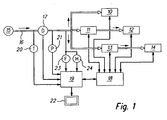
- FIG. 1 a pneumatic system is shown schematically, which could in principle also be another fluidic system, such as a hydraulic system, act.
- the pneumatic system consists of five subsystems 10 to 14, which may each be actuators, such as valves, cylinders, linear drives and the like, act, as well as Combinations thereof. These subsystems 10 to 14 are fed by a pressure source 15, wherein in a common supply line 16, a flow meter 17 for measuring the flow or the volume flow is arranged.
- An electronic control device 18 is used to specify the process flow of the system and is electrically connected to the subsystems 10 to 14 via corresponding control lines.
- the subsystems 10 to 14 receive control signals from the electronic control device 18 and send sensor signals back to them.
- sensor signals are, for example, position signals, limit switch signals, pressure signals, temperature signals and the like.
- the flow meter 17 is connected to an electronic diagnostic device 19, which in addition to the signals of a temperature sensor 20 and a pressure sensor 21 for measuring the temperature (T) and the pressure (P) in the supply line 16, ie the temperature and the pressure of the fluid supplied are. Furthermore, a fluid sensor 23 for detecting the type of fluid used and a moisture and / or particle sensor 24 for detecting the moisture content and the particle content of the fluid are connected to the diagnostic device 19. This has additional access to the sequence program of the electronic control device 18. The diagnostic results are supplied to a display 22, these diagnostic results of course also stored, printed, visually and / or acoustically displayed or a central office via lines or wirelessly can be transmitted.
- the diagnostic device 19 can also be integrated in the electronic control device 18, which may contain, for example, a microcontroller for carrying out the sequence program and optionally for diagnosis.
- each group has its own flow meter 17 to independently diagnose the subregions of the system associated with the groups, as described in the above-mentioned prior art.
- the procedure for fault isolation and diagnosis will now be described below with reference to the described pneumatic system and in the FIGS. 2 to 4 illustrated Leitwertdiagramme explained.
- the influences of the temperature T and / or the characteristic values K F or K H can also not be taken into account, so that in the simplest case the conductance depends only on the volume flow and the admission pressure.
- the conductivity is additionally dependent on time and / or batch, that is, depending on the operating condition, other conductance curves arise.
- Such operating states are, for example, the warm-up, the operation after a long standstill, the reclosure when retrofitting or the operation after predetermined time intervals, so for example after a one-hour or ten-hour or several hours of operation.
- the diagnostic control value or the diagnostic control values are characteristic variables of a fluidic system or a fluidic system that consists of a variety of subsystems.
- the conductance characterizes the behavior of the entire system or a subsystem over a defined repeating cycle. It compensates for normal fluctuations and fluctuations in the operating variables pressure, temperature, humidity, particle content, depending on how complex it is formed.
- the evaluation of this conductance by reference comparison, ie comparison with stored master value reference curves, thus showing the errors and the causes of errors in fluidic systems.
- a parameter-dependent master value reference curve adapted to the respective operating state must be selected. This takes place initially as a function of the applied sensor signals. Then, the runtime of the system is first checked as a function of the respective operating state and checked for correlation with the initially selected master reference curve. If the selected master value reference curve correlates with the current measured curve, the diagnosis is released. Deviations then actually indicate a leak in the detected period and can be assigned to these error-causing actuators in accordance with the sequence program.
- the diagnosis is released, that is, the Deviation does not stem from a time shift, but from a malfunction of the plant ago, in particular from a leak.
- the measured conductance curve K Da deviates continuously more and more from the conductance reference curve K Dref .
- the difference ⁇ K D increases more and more with time t and is a function of time.
- a deviation ⁇ K D occurs, which remains constant from this point in time until the end t e of the cycle.
- a subsystem for example a valve actuator unit that was active at time t1
- the timing of the deviation may be compared with the process image or control program in the controller 18 to locate the error-causing subsystem. If several subsystems were active at time t1, which could be the case for larger systems, the error must be limited during the following activities of these subsystems in which they are no longer active together.
- the cycle duration has changed by the value .DELTA.t, the change having occurred at the time t2.
- the value of the conductance remains constant from this time t2, there is only a time shift. This allows the conclusion that the travel time of the active at this time t2 actuator has changed, for example, by clamping, increased wear, switching errors on the valve or the like. It is thus also possible to detect time errors in the pneumatic system based on the conductance.
- FIGS. 2 to 4 reported occurrences during a cycle cumulative and / or occur multiple times. By corresponding curve, several different errors occurring during a cycle can then be detected. For safety, of course, the diagnostic cycles will be repeated upon the occurrence of a fault to determine if it is a one-time fault or a faulty measurement or fault.
Claims (9)
- Procédé de localisation de défaut et de diagnostic d'une installation fluidique, sachant que le débit volumique de l'ensemble de l'installation ou d'au moins une région partielle de celle-ci, ainsi que la pression du fluide, sont respectivement enregistrés pendant un cycle opératoire, et sont comparés à des références mémorisées, et sachant que chaque fois au moment d'un écart ou d'une modification de l'écart par rapport à la référence, on détermine pour quel composant ou pour quels composants de l'installation a eu lieu un processus influençant la consommation de fluide, afin d'identifier alors ce ou ces composants comme défectueux, caractérisé en ce que, à partir des valeurs respectives de débit volumique (Q) et de la pression mesurée (P), on forme des grandeurs directrices (Q/P) et on les intègre ou on les totalise sur le cycle opératoire pour former des valeurs directrices (KD), sachant qu'on sélectionne comme référence une courbe de référence de valeurs directrices (KDref) correspondante, à partir d'une matrice de sélection mémorisée qui contient des courbes de référence de valeurs directrices (KDref) ou des valeurs directrices en fonction du temps pour différents états opératoires.
- Procédé selon la revendication 1, caractérisé en ce que les différents états opératoires sont au moins deux des états opératoires suivants : mise en température, fonctionnement après une longue immobilisation, redémarrage suite à une modification de l'équipement, fonctionnement au bout d'intervalles de temps prédéterminables.
- Procédé selon la revendication 1 ou 2, caractérisé en ce que les grandeurs directrices sont compensées en fonction de la température, notamment par le facteur

- Procédé selon l'une des revendications précédentes, caractérisé en ce que les grandeurs directrices sont compensées en fonction du fluide, notamment par le facteur

- Procédé selon l'une des revendications précédentes, caractérisé en ce que les grandeurs directrices sont adaptées par la teneur en humidité et/ou la teneur en particules du fluide, notamment par le facteur

- Procédé selon l'une des revendications précédentes, caractérisé en ce que, avant le diagnostic de fuite, on vérifie la durée d'exécution d'un cycle opératoire en comparant la courbe de mesure de valeurs directrices actuelle (KDa) à une courbe de référence de valeurs directrices (KDref) associée à ce cycle opératoire, sachant que le passage à au moins une autre courbe de référence de valeurs directrices (KDref) ne s'effectue qu'à partir d'un écart prédéterminable.
- Procédé selon la revendication 6, caractérisé en ce que, en cas de constatation d'un écart de durée d'exécution, on vérifie en outre la présence d'un décalage de temps proportionnel entre les courbes de mesure de valeurs directrices actuelles (KDa) et les courbes de référence de valeurs directrices (KDref), et le passage à au moins une autre courbe de référence de valeurs directrices (KDref) ne s'effectue qu'en cas de constatation d'un décalage de temps proportionnel.
- Procédé selon la revendication 6 ou 7, caractérisé en ce que, en cas de dépassement de l'écart prédéterminable pour toutes les courbes de référence de valeurs directrices (KDref) vérifiées, un message correspondant est produit et le diagnostic de fuite n'est pas effectué.
- Procédé selon l'une des revendications précédentes, caractérisé en ce que, en présence d'un nombre important de composants (10-14), on effectue une répartition en plusieurs groupes qui sont diagnostiqués indépendamment les uns des autres.
Applications Claiming Priority (1)
| Application Number | Priority Date | Filing Date | Title |
|---|---|---|---|
| PCT/EP2007/001268 WO2008098588A1 (fr) | 2007-02-14 | 2007-02-14 | Procédé de localisation de défaut et de diagnostic d'une installation fluidique |
Publications (2)
| Publication Number | Publication Date |
|---|---|
| EP2047117A1 EP2047117A1 (fr) | 2009-04-15 |
| EP2047117B1 true EP2047117B1 (fr) | 2010-06-16 |
Family
ID=38523366
Family Applications (1)
| Application Number | Title | Priority Date | Filing Date |
|---|---|---|---|
| EP07703455A Active EP2047117B1 (fr) | 2007-02-14 | 2007-02-14 | Procédé de localisation de défaut et de diagnostic d'une installation fluidique |
Country Status (8)
| Country | Link |
|---|---|
| US (1) | US7941290B2 (fr) |
| EP (1) | EP2047117B1 (fr) |
| KR (1) | KR20100014066A (fr) |
| CN (1) | CN101454580B (fr) |
| AT (1) | ATE471461T1 (fr) |
| DE (1) | DE502007004150D1 (fr) |
| TW (1) | TWI424953B (fr) |
| WO (1) | WO2008098588A1 (fr) |
Families Citing this family (18)
| Publication number | Priority date | Publication date | Assignee | Title |
|---|---|---|---|---|
| US10338580B2 (en) | 2014-10-22 | 2019-07-02 | Ge Global Sourcing Llc | System and method for determining vehicle orientation in a vehicle consist |
| US10464579B2 (en) | 2006-04-17 | 2019-11-05 | Ge Global Sourcing Llc | System and method for automated establishment of a vehicle consist |
| NO326874B1 (no) * | 2006-10-20 | 2009-03-09 | Aker Subsea As | System og fremgangsmåte for overvåking av undersjøiske akkumulatorbanker |
| US10031042B2 (en) | 2009-08-18 | 2018-07-24 | Innovative Pressure Testing, Llc | System and method for detecting leaks |
| CN102338137A (zh) * | 2011-08-25 | 2012-02-01 | 中联重科股份有限公司 | 检测液压阀的方法、控制器和装置、检测液压回路故障的方法和装置以及故障处理系统 |
| WO2013026209A1 (fr) * | 2011-08-25 | 2013-02-28 | 长沙中联重工科技发展股份有限公司 | Procédé, dispositif de commande et dispositif de détection d'une soupape hydraulique dans un circuit hydraulique, procédé et dispositif de détection de panne de circuit hydraulique, et système de traitement de panne pour circuit hydraulique |
| US9897082B2 (en) | 2011-09-15 | 2018-02-20 | General Electric Company | Air compressor prognostic system |
| US20130280095A1 (en) * | 2012-04-20 | 2013-10-24 | General Electric Company | Method and system for reciprocating compressor starting |
| US10301930B2 (en) | 2013-10-17 | 2019-05-28 | Innovative Pressure Testing, Llc | System and method for a benchmark pressure test |
| CA2926288C (fr) | 2013-10-17 | 2020-04-14 | Innovative Pressure Testing, Llc | Systeme et procede pour essai de pression etalon |
| CN105371925A (zh) * | 2014-08-08 | 2016-03-02 | 北京谊安医疗系统股份有限公司 | 一种麻醉机流量传感器校准方法 |
| KR102243826B1 (ko) * | 2014-10-01 | 2021-04-23 | 삼성전자주식회사 | 냉장고 및 그 제어 방법 |
| KR101909113B1 (ko) * | 2016-11-30 | 2018-10-18 | (주)티에프에스글로발 | 휴대용 전기-유압 컨버터 및 서보모터의 자동교정 판정장치 |
| CN107764483B (zh) * | 2017-10-09 | 2019-05-21 | 中国水利水电科学研究院 | 基于温度时空分布矩阵的渗漏监控方法和装置 |
| DE102018203036A1 (de) * | 2018-03-01 | 2019-09-19 | Volkswagen Aktiengesellschaft | "Diagnoseverfahren zur Sprungerkennung einer kontinuierlichen Messgröße, Steuerung zur Durchführung des Verfahrens" |
| CN108563919B (zh) * | 2018-03-19 | 2022-04-19 | 中国石油化工股份有限公司 | 聚合物凝胶颗粒孔隙尺度运移的直接跟踪方法 |
| DE102019214882A1 (de) * | 2019-09-27 | 2021-04-01 | Zf Friedrichshafen Ag | Verfahren und Steuergerät zum Betreiben eines pneumatischen Druckstellersystems eines Getriebes |
| CN111947832A (zh) * | 2020-08-11 | 2020-11-17 | 董伟 | 一种基于互联网的压力表检测系统 |
Family Cites Families (8)
| Publication number | Priority date | Publication date | Assignee | Title |
|---|---|---|---|---|
| CN1095075C (zh) * | 1998-11-30 | 2002-11-27 | 浙江大学 | 液压系统泄漏故障诊断方法 |
| CN1138085C (zh) * | 1999-05-10 | 2004-02-11 | 北京昊科航科技有限责任公司 | 流体输送管道泄漏监测定位方法 |
| DE10052664B4 (de) * | 2000-10-24 | 2004-10-28 | Festo Ag & Co. | Vorrichtung zur Prozeßüberwachung |
| TW515878B (en) * | 2000-12-29 | 2003-01-01 | Inst Of Occupational Safty And | Hydraulic machine on-line monitoring and diagnosis device |
| JP3870814B2 (ja) * | 2002-03-29 | 2007-01-24 | 株式会社デンソー | 圧縮エア監視システム |
| CN1246672C (zh) * | 2002-07-04 | 2006-03-22 | 东北大学 | 流体输送管道泄漏智能故障诊断与定位的方法与装置 |
| WO2005111433A1 (fr) | 2004-04-16 | 2005-11-24 | Festo Ag & Co | Procede de localisation de defaut et diagnostic d'une installation fluidique |
| US7031850B2 (en) * | 2004-04-16 | 2006-04-18 | Festo Ag & Co. Kg | Method and apparatus for diagnosing leakage in a fluid power system |
-
2007
- 2007-02-14 EP EP07703455A patent/EP2047117B1/fr active Active
- 2007-02-14 WO PCT/EP2007/001268 patent/WO2008098588A1/fr active Application Filing
- 2007-02-14 CN CN2007800134292A patent/CN101454580B/zh not_active Expired - Fee Related
- 2007-02-14 KR KR1020087022799A patent/KR20100014066A/ko not_active Application Discontinuation
- 2007-02-14 US US12/085,338 patent/US7941290B2/en not_active Expired - Fee Related
- 2007-02-14 AT AT07703455T patent/ATE471461T1/de active
- 2007-02-14 DE DE502007004150T patent/DE502007004150D1/de active Active
-
2008
- 2008-02-12 TW TW097104869A patent/TWI424953B/zh not_active IP Right Cessation
Also Published As
| Publication number | Publication date |
|---|---|
| US7941290B2 (en) | 2011-05-10 |
| ATE471461T1 (de) | 2010-07-15 |
| CN101454580A (zh) | 2009-06-10 |
| DE502007004150D1 (de) | 2010-07-29 |
| US20100153027A1 (en) | 2010-06-17 |
| KR20100014066A (ko) | 2010-02-10 |
| EP2047117A1 (fr) | 2009-04-15 |
| TWI424953B (zh) | 2014-02-01 |
| TW200848355A (en) | 2008-12-16 |
| CN101454580B (zh) | 2012-08-01 |
| WO2008098588A1 (fr) | 2008-08-21 |
Similar Documents
| Publication | Publication Date | Title |
|---|---|---|
| EP2047117B1 (fr) | Procédé de localisation de défaut et de diagnostic d'une installation fluidique | |
| DE4106717C1 (fr) | ||
| EP1928675B1 (fr) | Procede et dispositif de detection de fuites dans un systeme d'amortissement pneumatique d'un vehicule | |
| DE102017211737B4 (de) | Überwachungsvorrichtung und Verfahren zur Überwachung eines Systems | |
| DE102013216255B3 (de) | Verfahren zur injektorindividuellen Diagnose einer Kraftstoff-Einspritzeinrichtung und Brennkraftmaschine mit einer Kraftstoff-Einspritzeinrichtung | |
| DE102012207655B4 (de) | Verfahren zur Diagnose eines Ventils einer Fluidzuleitung | |
| EP2047118B1 (fr) | Procédé de localisation de défaut et de diagnostic d'une installation fluidique | |
| DE102015012220A1 (de) | Verfahren zum Detektieren von Leckagen | |
| DE102013102071B4 (de) | Verfahren zum Überprüfen einer Funktion eines Auslassventiles | |
| DE102005034270A1 (de) | Verfahren zur Diagnose eines im Abgasbereich einer Brennkraftmaschine angeordneten Differenzdrucksensors und Vorrichtung zur Durchführung des Verfahrens | |
| DE102008001143A1 (de) | Verfahren zur Generierung von Ersatzwerten für Messwerte in einer Steuerung | |
| EP2184473A2 (fr) | Procédé et dispositif de vérification d'un capteur de pression d'un dispositif d'injection de carburant | |
| EP1747380B1 (fr) | Procede de localisation de defaut et diagnostic d'une installation fluidique | |
| DE102011100029B4 (de) | Vorrichtung zum Messen eines Kraftstoffflusses und Kalibriervorrichtung dafür | |
| DE102007018174A1 (de) | Verfahren zur Diagnose von technischen Systemen, insbesondere im Kraftfahrzeugbereich | |
| DE102014211880A1 (de) | Kraftstoffzuführungssystem und Verfahren zum Lokalisieren eines Lecks in einem Kraftstoffzuführungssystem | |
| DE10355022A1 (de) | Verfahren zur Überwachung eines technischen Systems | |
| DE102004005446A1 (de) | Mit Brennstoff betreibbare Vorrichtung zur Wandlung von Energie, insbesondere Brennstoffzellenvorrichtung | |
| DE102007014325B4 (de) | Verfahren und Vorrichtung zur Überwachung eines Drucksignals, insbesondere eines Raildrucksignals eines Common-Rails-Systems | |
| DE102016206609A1 (de) | Verfahren zur Überprüfung eines Stickoxidsensors eines Verbrennungsmotors | |
| DE102017222559B4 (de) | Verfahren und Vorrichtung zur Vorhersage des Ausfallzeitpunktes des Druckbegrenzungsventils einer Kraftstoffhochdruckpumpe eines Kraftfahrzeugs | |
| DE102017125832B3 (de) | Verfahren zur Detektion eines Fehlers in einem System zur pneumatischen Verstellung eines Stellelements und computerlesbares Speichermedium | |
| EP2926014A2 (fr) | Procédé et dispositif permettant d'indiquer la position d'accessoires de robinetterie à commande hydraulique | |
| WO2018065223A1 (fr) | Procédé et dispositif pour déterminer un état de détérioration d'un composant d'un véhicule | |
| DE102018222218B4 (de) | Verfahren zum Prüfen eines Hydrauliksystems |
Legal Events
| Date | Code | Title | Description |
|---|---|---|---|
| PUAI | Public reference made under article 153(3) epc to a published international application that has entered the european phase |
Free format text: ORIGINAL CODE: 0009012 |
|
| 17P | Request for examination filed |
Effective date: 20080129 |
|
| AK | Designated contracting states |
Kind code of ref document: A1 Designated state(s): AT BE BG CH CY CZ DE DK EE ES FI FR GB GR HU IE IS IT LI LT LU LV MC NL PL PT RO SE SI SK TR |
|
| AX | Request for extension of the european patent |
Extension state: AL BA HR MK RS |
|
| RIN1 | Information on inventor provided before grant (corrected) |
Inventor name: BREDAU, JAN Inventor name: KELLER, REINHARD |
|
| GRAP | Despatch of communication of intention to grant a patent |
Free format text: ORIGINAL CODE: EPIDOSNIGR1 |
|
| GRAC | Information related to communication of intention to grant a patent modified |
Free format text: ORIGINAL CODE: EPIDOSCIGR1 |
|
| DAX | Request for extension of the european patent (deleted) | ||
| GRAS | Grant fee paid |
Free format text: ORIGINAL CODE: EPIDOSNIGR3 |
|
| GRAA | (expected) grant |
Free format text: ORIGINAL CODE: 0009210 |
|
| AK | Designated contracting states |
Kind code of ref document: B1 Designated state(s): AT BE BG CH CY CZ DE DK EE ES FI FR GB GR HU IE IS IT LI LT LU LV MC NL PL PT RO SE SI SK TR |
|
| REG | Reference to a national code |
Ref country code: CH Ref legal event code: EP |
|
| REG | Reference to a national code |
Ref country code: IE Ref legal event code: FG4D Free format text: LANGUAGE OF EP DOCUMENT: GERMAN |
|
| REF | Corresponds to: |
Ref document number: 502007004150 Country of ref document: DE Date of ref document: 20100729 Kind code of ref document: P |
|
| REG | Reference to a national code |
Ref country code: NL Ref legal event code: T3 |
|
| PG25 | Lapsed in a contracting state [announced via postgrant information from national office to epo] |
Ref country code: SE Free format text: LAPSE BECAUSE OF FAILURE TO SUBMIT A TRANSLATION OF THE DESCRIPTION OR TO PAY THE FEE WITHIN THE PRESCRIBED TIME-LIMIT Effective date: 20100616 Ref country code: LT Free format text: LAPSE BECAUSE OF FAILURE TO SUBMIT A TRANSLATION OF THE DESCRIPTION OR TO PAY THE FEE WITHIN THE PRESCRIBED TIME-LIMIT Effective date: 20100616 |
|
| LTIE | Lt: invalidation of european patent or patent extension |
Effective date: 20100616 |
|
| PG25 | Lapsed in a contracting state [announced via postgrant information from national office to epo] |
Ref country code: SI Free format text: LAPSE BECAUSE OF FAILURE TO SUBMIT A TRANSLATION OF THE DESCRIPTION OR TO PAY THE FEE WITHIN THE PRESCRIBED TIME-LIMIT Effective date: 20100616 Ref country code: LV Free format text: LAPSE BECAUSE OF FAILURE TO SUBMIT A TRANSLATION OF THE DESCRIPTION OR TO PAY THE FEE WITHIN THE PRESCRIBED TIME-LIMIT Effective date: 20100616 Ref country code: FI Free format text: LAPSE BECAUSE OF FAILURE TO SUBMIT A TRANSLATION OF THE DESCRIPTION OR TO PAY THE FEE WITHIN THE PRESCRIBED TIME-LIMIT Effective date: 20100616 |
|
| PG25 | Lapsed in a contracting state [announced via postgrant information from national office to epo] |
Ref country code: CY Free format text: LAPSE BECAUSE OF FAILURE TO SUBMIT A TRANSLATION OF THE DESCRIPTION OR TO PAY THE FEE WITHIN THE PRESCRIBED TIME-LIMIT Effective date: 20100616 Ref country code: PL Free format text: LAPSE BECAUSE OF FAILURE TO SUBMIT A TRANSLATION OF THE DESCRIPTION OR TO PAY THE FEE WITHIN THE PRESCRIBED TIME-LIMIT Effective date: 20100616 |
|
| REG | Reference to a national code |
Ref country code: IE Ref legal event code: FD4D |
|
| PG25 | Lapsed in a contracting state [announced via postgrant information from national office to epo] |
Ref country code: EE Free format text: LAPSE BECAUSE OF FAILURE TO SUBMIT A TRANSLATION OF THE DESCRIPTION OR TO PAY THE FEE WITHIN THE PRESCRIBED TIME-LIMIT Effective date: 20100616 Ref country code: IE Free format text: LAPSE BECAUSE OF FAILURE TO SUBMIT A TRANSLATION OF THE DESCRIPTION OR TO PAY THE FEE WITHIN THE PRESCRIBED TIME-LIMIT Effective date: 20100616 |
|
| PG25 | Lapsed in a contracting state [announced via postgrant information from national office to epo] |
Ref country code: RO Free format text: LAPSE BECAUSE OF FAILURE TO SUBMIT A TRANSLATION OF THE DESCRIPTION OR TO PAY THE FEE WITHIN THE PRESCRIBED TIME-LIMIT Effective date: 20100616 Ref country code: SK Free format text: LAPSE BECAUSE OF FAILURE TO SUBMIT A TRANSLATION OF THE DESCRIPTION OR TO PAY THE FEE WITHIN THE PRESCRIBED TIME-LIMIT Effective date: 20100616 Ref country code: PT Free format text: LAPSE BECAUSE OF FAILURE TO SUBMIT A TRANSLATION OF THE DESCRIPTION OR TO PAY THE FEE WITHIN THE PRESCRIBED TIME-LIMIT Effective date: 20101018 Ref country code: IS Free format text: LAPSE BECAUSE OF FAILURE TO SUBMIT A TRANSLATION OF THE DESCRIPTION OR TO PAY THE FEE WITHIN THE PRESCRIBED TIME-LIMIT Effective date: 20101016 Ref country code: CZ Free format text: LAPSE BECAUSE OF FAILURE TO SUBMIT A TRANSLATION OF THE DESCRIPTION OR TO PAY THE FEE WITHIN THE PRESCRIBED TIME-LIMIT Effective date: 20100616 |
|
| PLBE | No opposition filed within time limit |
Free format text: ORIGINAL CODE: 0009261 |
|
| STAA | Information on the status of an ep patent application or granted ep patent |
Free format text: STATUS: NO OPPOSITION FILED WITHIN TIME LIMIT |
|
| PG25 | Lapsed in a contracting state [announced via postgrant information from national office to epo] |
Ref country code: DK Free format text: LAPSE BECAUSE OF FAILURE TO SUBMIT A TRANSLATION OF THE DESCRIPTION OR TO PAY THE FEE WITHIN THE PRESCRIBED TIME-LIMIT Effective date: 20100616 |
|
| 26N | No opposition filed |
Effective date: 20110317 |
|
| PG25 | Lapsed in a contracting state [announced via postgrant information from national office to epo] |
Ref country code: GR Free format text: LAPSE BECAUSE OF FAILURE TO SUBMIT A TRANSLATION OF THE DESCRIPTION OR TO PAY THE FEE WITHIN THE PRESCRIBED TIME-LIMIT Effective date: 20100917 |
|
| REG | Reference to a national code |
Ref country code: DE Ref legal event code: R097 Ref document number: 502007004150 Country of ref document: DE Effective date: 20110316 |
|
| BERE | Be: lapsed |
Owner name: FESTO A.G. & CO. KG Effective date: 20110228 |
|
| PG25 | Lapsed in a contracting state [announced via postgrant information from national office to epo] |
Ref country code: MC Free format text: LAPSE BECAUSE OF NON-PAYMENT OF DUE FEES Effective date: 20110228 |
|
| REG | Reference to a national code |
Ref country code: CH Ref legal event code: PL |
|
| PG25 | Lapsed in a contracting state [announced via postgrant information from national office to epo] |
Ref country code: LI Free format text: LAPSE BECAUSE OF NON-PAYMENT OF DUE FEES Effective date: 20110228 Ref country code: CH Free format text: LAPSE BECAUSE OF NON-PAYMENT OF DUE FEES Effective date: 20110228 |
|
| PG25 | Lapsed in a contracting state [announced via postgrant information from national office to epo] |
Ref country code: BE Free format text: LAPSE BECAUSE OF NON-PAYMENT OF DUE FEES Effective date: 20110228 |
|
| PGFP | Annual fee paid to national office [announced via postgrant information from national office to epo] |
Ref country code: NL Payment date: 20120227 Year of fee payment: 6 |
|
| PGFP | Annual fee paid to national office [announced via postgrant information from national office to epo] |
Ref country code: AT Payment date: 20120221 Year of fee payment: 6 |
|
| PG25 | Lapsed in a contracting state [announced via postgrant information from national office to epo] |
Ref country code: LU Free format text: LAPSE BECAUSE OF NON-PAYMENT OF DUE FEES Effective date: 20110214 |
|
| REG | Reference to a national code |
Ref country code: NL Ref legal event code: V1 Effective date: 20130901 |
|
| PG25 | Lapsed in a contracting state [announced via postgrant information from national office to epo] |
Ref country code: TR Free format text: LAPSE BECAUSE OF FAILURE TO SUBMIT A TRANSLATION OF THE DESCRIPTION OR TO PAY THE FEE WITHIN THE PRESCRIBED TIME-LIMIT Effective date: 20100616 Ref country code: BG Free format text: LAPSE BECAUSE OF FAILURE TO SUBMIT A TRANSLATION OF THE DESCRIPTION OR TO PAY THE FEE WITHIN THE PRESCRIBED TIME-LIMIT Effective date: 20100916 |
|
| REG | Reference to a national code |
Ref country code: AT Ref legal event code: MM01 Ref document number: 471461 Country of ref document: AT Kind code of ref document: T Effective date: 20130228 |
|
| PG25 | Lapsed in a contracting state [announced via postgrant information from national office to epo] |
Ref country code: ES Free format text: LAPSE BECAUSE OF FAILURE TO SUBMIT A TRANSLATION OF THE DESCRIPTION OR TO PAY THE FEE WITHIN THE PRESCRIBED TIME-LIMIT Effective date: 20100927 Ref country code: AT Free format text: LAPSE BECAUSE OF NON-PAYMENT OF DUE FEES Effective date: 20130228 Ref country code: NL Free format text: LAPSE BECAUSE OF NON-PAYMENT OF DUE FEES Effective date: 20130901 Ref country code: HU Free format text: LAPSE BECAUSE OF FAILURE TO SUBMIT A TRANSLATION OF THE DESCRIPTION OR TO PAY THE FEE WITHIN THE PRESCRIBED TIME-LIMIT Effective date: 20100616 |
|
| PGFP | Annual fee paid to national office [announced via postgrant information from national office to epo] |
Ref country code: GB Payment date: 20150127 Year of fee payment: 9 |
|
| REG | Reference to a national code |
Ref country code: FR Ref legal event code: PLFP Year of fee payment: 10 |
|
| PGFP | Annual fee paid to national office [announced via postgrant information from national office to epo] |
Ref country code: FR Payment date: 20160222 Year of fee payment: 10 |
|
| GBPC | Gb: european patent ceased through non-payment of renewal fee |
Effective date: 20160214 |
|
| PG25 | Lapsed in a contracting state [announced via postgrant information from national office to epo] |
Ref country code: GB Free format text: LAPSE BECAUSE OF NON-PAYMENT OF DUE FEES Effective date: 20160214 |
|
| PGFP | Annual fee paid to national office [announced via postgrant information from national office to epo] |
Ref country code: IT Payment date: 20170217 Year of fee payment: 11 |
|
| REG | Reference to a national code |
Ref country code: FR Ref legal event code: ST Effective date: 20171031 |
|
| PG25 | Lapsed in a contracting state [announced via postgrant information from national office to epo] |
Ref country code: FR Free format text: LAPSE BECAUSE OF NON-PAYMENT OF DUE FEES Effective date: 20170228 |
|
| PG25 | Lapsed in a contracting state [announced via postgrant information from national office to epo] |
Ref country code: IT Free format text: LAPSE BECAUSE OF NON-PAYMENT OF DUE FEES Effective date: 20180214 |
|
| REG | Reference to a national code |
Ref country code: DE Ref legal event code: R082 Ref document number: 502007004150 Country of ref document: DE Representative=s name: PATENTANWAELTE MAGENBAUER & KOLLEGEN PARTNERSC, DE Ref country code: DE Ref legal event code: R081 Ref document number: 502007004150 Country of ref document: DE Owner name: FESTO SE & CO. KG, DE Free format text: FORMER OWNER: FESTO AG & CO. KG, 73734 ESSLINGEN, DE Ref country code: DE Ref legal event code: R081 Ref document number: 502007004150 Country of ref document: DE Owner name: FESTO AG & CO. KG, DE Free format text: FORMER OWNER: FESTO AG & CO. KG, 73734 ESSLINGEN, DE |
|
| PGFP | Annual fee paid to national office [announced via postgrant information from national office to epo] |
Ref country code: DE Payment date: 20220609 Year of fee payment: 17 |
|
| P01 | Opt-out of the competence of the unified patent court (upc) registered |
Effective date: 20230623 |