EP2045686B1 - Lithographic apparatus and associated vibration damping method - Google Patents
Lithographic apparatus and associated vibration damping method Download PDFInfo
- Publication number
- EP2045686B1 EP2045686B1 EP20080165684 EP08165684A EP2045686B1 EP 2045686 B1 EP2045686 B1 EP 2045686B1 EP 20080165684 EP20080165684 EP 20080165684 EP 08165684 A EP08165684 A EP 08165684A EP 2045686 B1 EP2045686 B1 EP 2045686B1
- Authority
- EP
- European Patent Office
- Prior art keywords
- filter unit
- lithographic apparatus
- partial order
- projection system
- order filter
- Prior art date
- Legal status (The legal status is an assumption and is not a legal conclusion. Google has not performed a legal analysis and makes no representation as to the accuracy of the status listed.)
- Expired - Fee Related
Links
Images


Classifications
-
- G—PHYSICS
- G03—PHOTOGRAPHY; CINEMATOGRAPHY; ANALOGOUS TECHNIQUES USING WAVES OTHER THAN OPTICAL WAVES; ELECTROGRAPHY; HOLOGRAPHY
- G03F—PHOTOMECHANICAL PRODUCTION OF TEXTURED OR PATTERNED SURFACES, e.g. FOR PRINTING, FOR PROCESSING OF SEMICONDUCTOR DEVICES; MATERIALS THEREFOR; ORIGINALS THEREFOR; APPARATUS SPECIALLY ADAPTED THEREFOR
- G03F7/00—Photomechanical, e.g. photolithographic, production of textured or patterned surfaces, e.g. printing surfaces; Materials therefor, e.g. comprising photoresists; Apparatus specially adapted therefor
- G03F7/70—Microphotolithographic exposure; Apparatus therefor
- G03F7/70691—Handling of masks or workpieces
- G03F7/70775—Position control, e.g. interferometers or encoders for determining the stage position
-
- G—PHYSICS
- G03—PHOTOGRAPHY; CINEMATOGRAPHY; ANALOGOUS TECHNIQUES USING WAVES OTHER THAN OPTICAL WAVES; ELECTROGRAPHY; HOLOGRAPHY
- G03F—PHOTOMECHANICAL PRODUCTION OF TEXTURED OR PATTERNED SURFACES, e.g. FOR PRINTING, FOR PROCESSING OF SEMICONDUCTOR DEVICES; MATERIALS THEREFOR; ORIGINALS THEREFOR; APPARATUS SPECIALLY ADAPTED THEREFOR
- G03F7/00—Photomechanical, e.g. photolithographic, production of textured or patterned surfaces, e.g. printing surfaces; Materials therefor, e.g. comprising photoresists; Apparatus specially adapted therefor
- G03F7/70—Microphotolithographic exposure; Apparatus therefor
- G03F7/708—Construction of apparatus, e.g. environment aspects, hygiene aspects or materials
- G03F7/70858—Environment aspects, e.g. pressure of beam-path gas, temperature
- G03F7/709—Vibration, e.g. vibration detection, compensation, suppression or isolation
-
- G—PHYSICS
- G05—CONTROLLING; REGULATING
- G05D—SYSTEMS FOR CONTROLLING OR REGULATING NON-ELECTRIC VARIABLES
- G05D19/00—Control of mechanical oscillations, e.g. of amplitude, of frequency, of phase
- G05D19/02—Control of mechanical oscillations, e.g. of amplitude, of frequency, of phase characterised by the use of electric means
Definitions
- the present invention relates to a control system to control a position or position related quantity such as velocity or acceleration of an object, a lithographic apparatus including a control system and a method for increasing the bandwidth of a position control system.
- a lithographic apparatus is a machine that applies a desired pattern onto a substrate, usually onto a target portion of the substrate.
- a lithographic apparatus can be used, for example, in the manufacture of integrated circuits (ICs).
- a patterning device which is alternatively referred to as a mask or a reticle, may be used to generate a circuit pattern to be formed on an individual layer of the IC.
- This pattern can be transferred onto a target portion (e.g. including part of, one, or several dies) on a substrate (e.g. a silicon wafer). Transfer of the pattern is typically via imaging onto a layer of radiation-sensitive material (resist) provided on the substrate.
- resist radiation-sensitive material
- a single substrate will contain a network of adjacent target portions that are successively patterned.
- Conventional lithographic apparatus include so-called steppers, in which each target portion is irradiated by exposing an entire pattern onto the target portion at once, and so-called scanners, in which each target portion is irradiated by scanning the pattern through a radiation beam in a given direction (the "scanning"-direction) while synchronously scanning the substrate parallel or anti-parallel to this direction. It is also possible to transfer the pattern from the patterning device to the substrate by imprinting the pattern onto the substrate.
- US 2002/149754 discloses a lithographic apparatus comprising an illumination system configured to condition a radiation beam, a patterning device support constructed to support a patterning device, said patterning device being capable of imparting the radiation beam with a pattern in its cross-section to form a patterned radiation beam, a substrate table constructed to hold a substrate, a projection system configured to project the patterned radiation beam onto a target portion of the substrate and an active damping system to control a velocity of the projection system.
- US 2007/097340 discloses an apparatus for actively damping vibrations associated with an optical assembly of a photolithographic system. A controller controls the force applied by the active mechanism on the structure, and utilizes information associated with movement of the structure to control the force.
- WO 2005/121901 discloses an active vibration control system of a first and second structural element and a first and second resilient element and equipped with an actuator, a controller and at least one sensor.
- the controller provides a compensation signal to the actuator, which provides an actuating force based on the compensation signal.
- partial order filter units to enhance the performance of control systems or as an alternative for complex integer order control systems is known from US 5 371 670 disclosing a controller with a fractional order PID compensator and the articles TOM T HARTLEY ET AL: "A Frequency-Domain Approach to Optimal Fractional-Order Damping" NONLINEAR DYNAMICS, KLUWER ACADEMIC PUBLISHERS, DO, vol. 38, no.
- a vibration control system including a control system for controlling a position or position related quantity, comprising a measurement system configured to measure a position or position related quantity (linear acceleration) of the object, configured to provide a control signal configured to actuate the object based on the control signal, and a filter unit configured to filter the measured position or position related quantity, wherein the filter unit is a [digital] filter unit.
- control systems are used to control the position or position related quantities such as velocity or acceleration of an object.
- a control system may be used to control the position of a movable object with high accuracy, for instance the servo control system of a substrate support or a patterning device support.
- a control system may be used to control the velocity or the acceleration of the object. Because velocity, acceleration and position of an object are closely related, velocity being the time integral of acceleration and position being the time integral of velocity, all three can be regarded as position related quantities of the object. For that reason, the term 'position control' may also be used for cases where velocity or acceleration or other position related quantities are the controlled variables.
- a control system may be used to stabilize the position of a substantially stationary object.
- Such control system is often referred to as an active damping system.
- an active damping system usually the velocity is the actual controlled variable
- Such a projection system includes a number of lens elements and/or mirrors and is held, during projection, in the optical path between a patterning device and substrate.
- the patterning device and substrate are positioned with respect to the projection system to obtain an optimal imaging quality.
- movements of the projection system may occur.
- a known embodiment of such control system includes an acceleration sensor to measure accelerations of the object, a controller to provide a control signal on the basis of the measured acceleration and an actuator to provide a reaction force to counteract the acceleration and therewith the movement of the object.
- the actuator is connected to the object and to a reaction mass.
- the mass is a free mass which means that it is only connected to the actuator.
- the reaction force is not exerted on for instance a frame.
- the reaction force could be exerted on a reaction frame or the like.
- a drawback of the known embodiment is that the control system may easily become unstable as for higher frequencies the gain of the transfer function of the system may increase while the phase crosses -180 degrees.
- the increasing gain is for instance a result of lens elements which are mounted with limited stiffness in the projection system, and become decoupled from the housing for frequencies above its resonance frequency. Applying the same force at a higher frequency therefore leads to a higher acceleration, because less mass is actuated when lens elements are decoupled. Therefore, the gain may increase for higher frequencies.
- the combination of high or even increasing gains for high frequencies increases the risk on an unstable system.
- a first or higher order low-pass filter is applied to dampen the high gains for higher frequencies to avoid instability of the system.
- the application of such a first of higher order low-pass filter may not be possible since the damping of the gains also implies a phase lag, therewith generally decreasing the frequency at which -180 degrees is crossed and increasing the chance on instability.
- the bandwidth of a position control system being defined as the first frequency where the gain of the open loop transfer function drops below one (0 dB). At the same time it is desired to have a stable system.
- Figure 1 depicts a lithographic apparatus according to an embodiment of the invention
- Figure 2 depicts a projection system and an active damping system according to an embodiment of the invention
- Figure 3 depicts a Bode plot of the transfer function between actuator force and acceleration of the projection system of Figure 2 ;
- Figure 4 depicts a Bode plot of the open loop of the prior art active damping system and projection system of Figure 2 ;
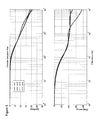
- Figure 5 depicts a Bode plot of half order filter approximated by rational transfer functions of different orders
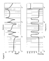
- Figure 6 depicts a Bode plot of low pass filters of first order, half order and 2/3 order.
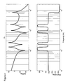
- Figure 7 depicts a Bode plot showing the results of the application of a partial order low-pass filter according to the present invention.
- FIG. 1 schematically depicts a lithographic apparatus according to one embodiment of the invention.
- the apparatus includes an illumination system (illuminator) IL configured to condition a radiation beam B (e.g. UV radiation or any other suitable radiation), a support structure or pattern support or support (e.g. a mask table) MT constructed to support a patterning device (e.g. a mask) MA and connected to a first positioning device PM configured to accurately position the patterning device in accordance with certain parameters.
- the apparatus also includes a substrate table (e.g. a wafer table) WT or "substrate support" constructed to hold a substrate (e.g. a resist-coated wafer) W and connected to a second positioning device PW configured to accurately position the substrate in accordance with certain parameters.
- a radiation beam B e.g. UV radiation or any other suitable radiation
- a support structure or pattern support or support e.g. a mask table
- MT constructed to support a patterning device (e.g. a
- the apparatus further includes a projection system (e.g. a refractive projection lens system) PS configured to project a pattern imparted to the radiation beam B by patterning device MA onto a target portion C (e.g. including one or more dies) of the substrate W.
- a projection system e.g. a refractive projection lens system
- PS configured to project a pattern imparted to the radiation beam B by patterning device MA onto a target portion C (e.g. including one or more dies) of the substrate W.
- the illumination system may include various types of optical components, such as refractive, reflective, magnetic, electromagnetic, electrostatic or other types of optical components, or any combination thereof, for directing, shaping, or controlling radiation.
- optical components such as refractive, reflective, magnetic, electromagnetic, electrostatic or other types of optical components, or any combination thereof, for directing, shaping, or controlling radiation.
- the support structure holds the patterning device in a manner that depends on the orientation of the patterning device, the design of the lithographic apparatus, and other conditions, such as for example whether or not the patterning device is held in a vacuum environment.
- the support structure can use mechanical, vacuum, electrostatic or other clamping techniques to hold the patterning device.
- the support structure may be a frame or a table, for example, which may be fixed or movable as required.
- the support structure may ensure that the patterning device is at a desired position, for example with respect to the projection system. Any use of the terms "reticle” or “mask” herein may be considered synonymous with the more general term "patterning device.”
- patterning device used herein should be broadly interpreted as referring to any device that can be used to impart a radiation beam with a pattern in its cross-section so as to create a pattern in a target portion of the substrate. It should be noted that the pattern imparted to the radiation beam may not exactly correspond to the desired pattern in the target portion of the substrate, for example if the pattern includes phase-shifting features or so called assist features. Generally, the pattern imparted to the radiation beam will correspond to a particular functional layer in a device being created in the target portion, such as an integrated circuit.
- the patterning device may be transmissive or reflective.
- Examples of patterning devices include masks, programmable mirror arrays, and programmable LCD panels.
- Masks are well known in lithography, and include mask types such as binary, alternating phase-shift, and attenuated phase-shift, as well as various hybrid mask types.
- An example of a programmable mirror array employs a matrix arrangement of small mirrors, each of which can be individually tilted so as to reflect an incoming radiation beam in different directions. The tilted mirrors impart a pattern in a radiation beam which is reflected by the mirror matrix.
- projection system used herein should be broadly interpreted as encompassing any type of projection system, including refractive, reflective, catadioptric, magnetic, electromagnetic and electrostatic optical systems, or any combination thereof, as appropriate for the exposure radiation being used, or for other factors such as the use of an immersion liquid or the use of a vacuum. Any use of the term “projection lens” herein may be considered as synonymous with the more general term “projection system”.
- the apparatus is of a transmissive type (e.g. employing a transmissive mask).
- the apparatus may be of a reflective type (e.g. employing a programmable mirror array of a type as referred to above, or employing a reflective mask).
- the lithographic apparatus may be of a type having two (dual stage) or more substrate tables or “substrate supports” (and/or two or more mask tables or “mask supports”).
- substrate tables or “substrate supports” and/or two or more mask tables or “mask supports”
- additional tables or supports may be used in parallel, or preparatory steps may be carried out on one or more tables or supports while one or more other tables or supports are being used for exposure.
- the lithographic apparatus may also be of a type wherein at least a portion of the substrate may be covered by a liquid having a relatively high refractive index, e.g. water, so as to fill a space between the projection system and the substrate.
- a liquid having a relatively high refractive index e.g. water
- An immersion liquid may also be applied to other spaces in the lithographic apparatus, for example, between the mask and the projection system. Immersion techniques can be used to increase the numerical aperture of projection systems.
- immersion as used herein does not mean that a structure, such as a substrate, must be submerged in liquid, but rather only means that a liquid is located between the projection system and the substrate during exposure.
- the illuminator IL receives a radiation beam from a radiation source SO.
- the source and the lithographic apparatus may be separate entities, for example when the source is an excimer laser. In such cases, the source is not considered to form part of the lithographic apparatus and the radiation beam is passed from the source SO to the illuminator IL with the aid of a beam delivery system BD including, for example, suitable directing mirrors and/or a beam expander. In other cases the source may be an integral part of the lithographic apparatus, for example when the source is a mercury lamp.
- the source SO and the illuminator IL, together with the beam delivery system BD if required, may be referred to as a radiation system.
- the illuminator IL may include an adjuster AD configured to adjust the angular intensity distribution of the radiation beam. Generally, at least the outer and/or inner radial extent (commonly referred to as ⁇ -outer and ⁇ -inner, respectively) of the intensity distribution in a pupil plane of the illuminator can be adjusted.
- the illuminator IL may include various other components, such as an integrator IN and a condenser CO. The illuminator may be used to condition the radiation beam, to have a desired uniformity and intensity distribution in its cross-section.
- the radiation beam B is incident on the patterning device (e.g., mask) MA, which is held on the support structure (e.g., mask table) MT, and is patterned by the patterning device. Having traversed the patterning device (e.g. mask) MA, the radiation beam B passes through the projection system PS, which focuses the beam onto a target portion C of the substrate W.
- the substrate table WT can be moved accurately, e.g. so as to position different target portions C in the path of the radiation beam B.
- the first positioning device PM and another position sensor can be used to accurately position the patterning device (e.g. mask) MA with respect to the path of the radiation beam B, e.g. after mechanical retrieval from a mask library, or during a scan.
- movement of the support structure (e.g. mask table) MT may be realized with the aid of a long-stroke module (coarse positioning) and a short-stroke module (fine positioning), which form part of the first positioning device PM.
- movement of the substrate table WT or "substrate support” may be realized using a long-stroke module and a short-stroke module, which form part of the second positioner PW.
- the support structure (e.g. mask table) MT may be connected to a short-stroke actuator only, or may be fixed.
- Patterning device (e.g. mask) MA and substrate W may be aligned using mask alignment marks M1, M2 and substrate alignment marks P1, P2.
- the substrate alignment marks as illustrated occupy dedicated target portions, they may be located in spaces between target portions (these are known as scribe-lane alignment marks).
- the mask alignment marks may be located between the dies.
- the depicted apparatus could be used in at least one of the following modes:
- step mode the support structure (e.g. mask table) MT or "mask support” and the substrate table WT or “substrate support” are kept essentially stationary, while an entire pattern imparted to the radiation beam is projected onto a target portion C at one time (i.e. a single static exposure).
- the substrate table WT or "substrate support” is then shifted in the X and/or Y direction so that a different target portion C can be exposed.
- the maximum size of the exposure field limits the size of the target portion C imaged in a single static exposure.
- the support structure (e.g. mask table) MT or "mask support” and the substrate table WT or “substrate support” are scanned synchronously while a pattern imparted to the radiation beam is projected onto a target portion C (i.e. a single dynamic exposure).
- the velocity and direction of the substrate table WT or "substrate support" relative to the support structure (e.g. mask table) MT or “mask support” may be determined by the (de-)magnification and image reversal characteristics of the projection system PS.
- the maximum size of the exposure field limits the width (in the non-scanning direction) of the target portion in a single dynamic exposure, whereas the length of the scanning motion determines the height (in the scanning direction) of the target portion.
- the support structure e.g. mask table
- the substrate table WT or "substrate support” is moved or scanned while a pattern imparted to the radiation beam is projected onto a target portion C.
- a pulsed radiation source is employed and the programmable patterning device is updated as required after each movement of the substrate table WT or "substrate support” or in between successive radiation pulses during a scan.
- This mode of operation can be readily applied to maskless lithography that utilizes programmable patterning device, such as a programmable mirror array of a type as referred to above.
- Figure 2 shows an active damping system 1 configured to control the velocity of a projection system 2.
- the damping device 1 is provided to minimize the velocity of the projection system 1, and therewith holding the projection system 1 in a substantially stationary position.
- External influences such as air flows and vibrations, for instance caused by movements of the patterning device support or substrate support, may excite the projection system 2.
- the active damping system 1 is provided.
- the active damping system 1 includes an acceleration sensor 3, a controller unit 4 and an actuator 5.
- the acceleration sensor 3 is configured to measure accelerations of the projection system 2 in at least one direction.
- the controller unit 4 is configured to provide a control signal on the basis of the measured acceleration.
- the control signal is fed to an actuator 4 which exerts a force on the projection system 2 in a direction opposite to the external disturbance force to damp out any movements excited by the disturbance force.
- the active damping device 1 as shown in Figure 2 only provides damping in a single direction.
- a damping device configured to damp movements in two or more directions or to provide two or more damping devices to damp out movements in two or more directions.
- the actuator is connected to a counter mass 6, which is only mechanically connected to the actuator.
- the actuator can only exert temporary forces and no permanent forces.
- permanent forces are normally not desired when the position control system is only used for damping of movements of the projection system 2.
- the reaction forces may be transferred to other parts of the lithographic apparatus, for instance a frame, which would allow exerting permanent forces.
- lens elements 8 are mounted in the interior of the housing 7 of the projection system 2 . These lens elements 8 are connected with limited stiffness to the housing 7. This limited stiffness acts as a spring. For increasing frequencies, the lens elements may become decoupled from the housing 7, in particular above the resonance frequency with which the element is mounted to housing 7. As a consequence, the relation between force and resulting acceleration has a relatively increasing gain, i.e. the acceleration becomes higher when the same force, but at higher frequencies is applied.
- Figure 3 shows a typical schematic Bode plot of the transfer between force and acceleration of this system.
- the transfer function from force to acceleration typically consists of a series of anti-resonance/resonance combinations, with a phase switching between 0 and +180 degrees, as can be seen in Figure 3 .
- the Bode plot shows an increasing gain for higher frequencies as mass of the lens elements 8 decouples from the system.
- a controller unit 4 having an integrator behavior (K/s). In alternative embodiments, other suitable types of controllers may also be applied.
- FIG. 4 A schematic open loop Bode plot of this control system is shown in Figure 4 . It can be seen that the system may become unstable. Generally, the amplitude becomes linearly smaller for higher frequencies, while the phase shifts between -90 and +90 degrees. However, at some point the phase will cross -180 degrees, for instance because of an internal resonance, in the present case at 8 kHz. Since the amplitude of the transfer function remains high for higher frequencies, as the mass of the lens elements 8 will decouple from the housing 6, instability may occur as the phase crosses the -180 degrees while the amplitude is larger than 0 dB.
- a partial order filter so that, at a desired frequency, the gain of the system may be decreased without obtaining a too large phase shift and therewith obtaining an unstable system.
- a half-order filter may provide a phase shift of 0 to -45 degrees and a gain slope of -10 dB per decade.
- Such partial order filter may provide a solution when some gain attenuation is desired, but there is no possibility to introduce a first order filter as 90 degrees phase shift would result in an unstable system.
- a practical application of a half order filter unit will now be described.
- every known implementation only is capable of using polynomials in s with integer coefficients.
- x 2 s 2 + 6 ⁇ s + 1 4 ⁇ s + 1
- x 3 s 4 + 28 ⁇ s 3 + 70 ⁇ s 2 + 28 ⁇ s + 1 8 ⁇ s + 1 ⁇ s 2 + 6 ⁇ s + 1 , etc.
- a higher frequency range is of interest (e.g. 10 to 10000 rad/s).
- a better approximation may be obtained by multiplying all poles and zeros in the approximating transfer function by a large number, for example by 3000, which effectively shifts the center frequency around which acceptable behavior occurs from 1 rad/s to 3000 rad/s (or from 0.16 Hz to 500 Hz).
- the resulting filter still approximates s .
- a start value other that 1 in the iteration process could be chosen. It was observed that the resulting filter will show acceptable behavior around the frequency equal to the iteration start value.
- filter units of another partial order may be applied.
- a higher roll-off can be obtained by using, e.g., a 2/3-order filter. This would give an average phase shift of -60 degrees, which would still be feasible, since there is still 30 degrees stability margin left when compared to a first order filter unit.
- x s / 3 2
- a transfer function containing numerator and denominator polynomials in s arises that includes a number of iterations to obtain an approximation of s / 3 2 .
- Filter orders are now 3, 9 and 27, respectively. Because of the above iteration formula's, orders tend to get higher rapidly in this case. It will be appreciated that other order partial filters may also be applied.
- Figure 6 shows a comparison between a prior art first-order low-pass filter, and partial order low-pass filter according to the invention, in particular a half-order low-pass filter and a 2/3-order low-pass filter as described above.
- the 1 ⁇ 2-order filter and 2/3-order filters use a third-order approximation, resulting in filter orders of 8 and 27, respectively.
- the half order filter has a phase shift of approximately -45 degrees
- the 2/3 order filter a phase shift of approximately -60 degrees
- the conventional first order filter has a phase shift of -90 degrees.
- the gain has a slope of -20 dB per decade for the first order filter, approximately -10 dB per decade for the half order filter and approximately -15 dB per decade for the 2/3-order filter.
- Figure 7 shows the results of the application of a half order low-pass filter unit and a low pass 2/3 order filter in the system shown in Figure 2 .
- the Bode plot of Figure 7 shows the plot of the open loop control system of Figure 4 without a low-pass filter, with a half order low-pass filter and a 2/3 order low-pass filter. All low-pass filters have a cutoff frequency of 100 Hz. The filters are gain adjusted such that at 500 Hz, the amplitude for all plots is the same. This way, up to at least 500 Hz the damping properties are not deteriorated by application of the partial low-pass filters. There is even some improvement, as the low-frequency amplitude has increased between 100 and 500 Hz..
- the filter orders of the partial low-pass filters are 8 and 9, respectively, for the 1 ⁇ 2 and 2/3 order filters. It can be seen that the 8 kHz peak has been reduced enough to ensure a stable system although the phase crosses -180 degrees, since the gain is substantially smaller than 0 dB.
- a partial order filter unit allows filtering over a large frequency range, because the phase lag is only a fraction of 90 degrees, e.g. for a half-order filter, the phase shift equals approximately 45 degrees.
- Implementation of the partial order filters uses for instance a polynomial transfer function or any other suitable transfer function that approximates s (half-order filter), or s / 3 2 (2/3-order filter).
- a partial filter unit may also be applied to increase the bandwidth of a position control system, since the phase shift resulting from the application of filters is no longer restricted by steps of -90 degrees per order of the filter unit.
- partial order low-pass filter units have been described to show the possible advantages of partial order filter units.
- Partial order filter units and their approximations by rational transfer functions may also be used for any other type of filter units such as band-pass filters, high pass filters, etc, wherein the above described characteristics of the partial order filter units are advantageous.
- the position control system/active damping device may include, next to the partial order filter unit, one or more filter units of first or higher orders, i.e. second, third, fourth, etc. Such combination may be applied as a series of separate filter units, but also as a combined filter unit for instance a 11 ⁇ 2 order filter unit. Such combined filter units are regarded to be a partial order filter unit according to the present invention.
- lithographic apparatus in the manufacture of ICs
- the lithographic apparatus described herein may have other applications, such as the manufacture of integrated optical systems, guidance and detection patterns for magnetic domain memories, flat-panel displays, liquid-crystal displays (LCDs), thin-film magnetic heads, etc.
- LCDs liquid-crystal displays
- any use of the terms “wafer” or “die” herein may be considered as synonymous with the more general terms “substrate” or "target portion”, respectively.
- the substrate referred to herein may be processed, before or after exposure, in for example a track (a tool that typically applies a layer of resist to a substrate and develops the exposed resist), a metrology tool and/or an inspection tool. Where applicable, the disclosure herein may be applied to such and other substrate processing tools. Further, the substrate may be processed more than once, for example in order to create a multi-layer IC, so that the term substrate used herein may also refer to a substrate that already contains multiple processed layers.
- imprint lithography a topography in a patterning device defines the pattern created on a substrate.
- the topography of the patterning device may be pressed into a layer of resist supplied to the substrate whereupon the resist is cured by applying electromagnetic radiation, heat, pressure or a combination thereof.
- the patterning device is moved out of the resist leaving a pattern in it after the resist is cured.
- UV radiation e.g. having a wavelength of or about 365, 248, 193, 157 or 126 nm
- EUV radiation e.g. having a wavelength in the range of 5-20 nm
- particle beams such as ion beams or electron beams.
- lens may refer to any one or combination of various types of optical components, including refractive, reflective, magnetic, electromagnetic and electrostatic optical components.
- the invention may take the form of a computer program containing one or more sequences of machine-readable instructions describing a method as disclosed above, or a data storage medium (e.g. semiconductor memory, magnetic or optical disk) having such a computer program stored therein.
- a data storage medium e.g. semiconductor memory, magnetic or optical disk
Landscapes
- General Physics & Mathematics (AREA)
- Physics & Mathematics (AREA)
- Engineering & Computer Science (AREA)
- Health & Medical Sciences (AREA)
- Toxicology (AREA)
- Environmental & Geological Engineering (AREA)
- Epidemiology (AREA)
- Public Health (AREA)
- Atmospheric Sciences (AREA)
- Life Sciences & Earth Sciences (AREA)
- Automation & Control Theory (AREA)
- Exposure And Positioning Against Photoresist Photosensitive Materials (AREA)
- Exposure Of Semiconductors, Excluding Electron Or Ion Beam Exposure (AREA)
- Control Of Position Or Direction (AREA)
Applications Claiming Priority (1)
| Application Number | Priority Date | Filing Date | Title |
|---|---|---|---|
| US96051407P | 2007-10-02 | 2007-10-02 |
Publications (3)
| Publication Number | Publication Date |
|---|---|
| EP2045686A2 EP2045686A2 (en) | 2009-04-08 |
| EP2045686A3 EP2045686A3 (en) | 2010-03-10 |
| EP2045686B1 true EP2045686B1 (en) | 2013-07-31 |
Family
ID=40018002
Family Applications (1)
| Application Number | Title | Priority Date | Filing Date |
|---|---|---|---|
| EP20080165684 Expired - Fee Related EP2045686B1 (en) | 2007-10-02 | 2008-10-02 | Lithographic apparatus and associated vibration damping method |
Country Status (7)
| Country | Link |
|---|---|
| US (1) | US8994919B2 (ja) |
| EP (1) | EP2045686B1 (ja) |
| JP (1) | JP5008630B2 (ja) |
| KR (1) | KR101023795B1 (ja) |
| CN (1) | CN101441420B (ja) |
| SG (1) | SG151245A1 (ja) |
| TW (1) | TWI390372B (ja) |
Families Citing this family (10)
| Publication number | Priority date | Publication date | Assignee | Title |
|---|---|---|---|---|
| US8164737B2 (en) | 2007-10-23 | 2012-04-24 | Asml Netherlands B.V. | Lithographic apparatus having an active damping subassembly |
| DE102011007917A1 (de) * | 2011-04-21 | 2012-10-25 | Asml Netherlands B.V. | Anordnung zur Aktuierung eines Elementes in einer mikrolithographischen Projektionsbelichtungsanlage |
| DE102011075393B4 (de) * | 2011-05-06 | 2013-08-14 | Carl Zeiss Smt Gmbh | Anordnung zur Aktuierung eines Elementes in einer Projektionsbelichtungsanlage |
| NL2009902A (en) * | 2011-12-27 | 2013-07-01 | Asml Netherlands Bv | Lithographic apparatus and device manufacturing method. |
| US10551751B2 (en) | 2012-04-26 | 2020-02-04 | Asml Netherlands B.V. | Lithography apparatus and device manufacturing method |
| US10888707B2 (en) | 2013-03-19 | 2021-01-12 | Genovus Biotechnologies Inc. | Muscle optimization device and method |
| US10322063B2 (en) | 2013-03-19 | 2019-06-18 | Genovus Biotechnologies Inc. | Muscle optimization device and method |
| AU2015231182B2 (en) * | 2014-03-19 | 2019-07-18 | Genovus Biotechnologies Inc. | Muscle optimization device and method |
| US10036963B2 (en) * | 2016-09-12 | 2018-07-31 | Cymer, Llc | Estimating a gain relationship of an optical source |
| US11169450B2 (en) | 2018-04-25 | 2021-11-09 | Asml Netherlands B.V. | Pneumatic support device and lithographic apparatus with pneumatic support device |
Family Cites Families (19)
| Publication number | Priority date | Publication date | Assignee | Title |
|---|---|---|---|---|
| JP2814241B2 (ja) | 1987-09-25 | 1998-10-22 | 株式会社ブリヂストン | 振動制御装置 |
| JPH01138663A (ja) * | 1987-11-26 | 1989-05-31 | Matsushita Electric Ind Co Ltd | ディスク装置の位置決め制御装置 |
| JPH03102683A (ja) * | 1989-09-14 | 1991-04-30 | Fujitsu Ltd | 磁気ディスク装置 |
| JP2774327B2 (ja) * | 1989-10-06 | 1998-07-09 | 日本電信電話株式会社 | 位置決め装置 |
| JPH0661791A (ja) * | 1992-08-04 | 1994-03-04 | Hitachi Ltd | フィルタ回路およびその制御方法 |
| US5371670A (en) * | 1993-02-01 | 1994-12-06 | The United States Of America As Represented By The Administrator Of The National Aeronautics And Space Administration | Three-parameter tunable tilt-integral-derivative (TID) controller |
| JP2001068396A (ja) * | 1999-08-26 | 2001-03-16 | Canon Inc | ステージ制御装置 |
| JP2001221279A (ja) * | 2000-02-09 | 2001-08-17 | Canon Inc | 能動制振装置 |
| JP3961311B2 (ja) * | 2001-01-19 | 2007-08-22 | エーエスエムエル ネザーランズ ビー.ブイ. | リソグラフィ装置およびデバイスの製造方法 |
| FR2825485B1 (fr) * | 2001-05-29 | 2005-02-18 | Alstom | Procede et dispositif de controle de vitesse angulaire d'une chaine electromecanique peu amortie |
| US20030169412A1 (en) * | 2002-03-08 | 2003-09-11 | Hazelton Andrew J. | Reaction frame for a wafer scanning stage with electromagnetic connections to ground |
| TWI230844B (en) * | 2002-06-07 | 2005-04-11 | Asml Netherlands Bv | Lithographic apparatus and device manufacturing method |
| JP4370113B2 (ja) * | 2003-03-18 | 2009-11-25 | オリンパス株式会社 | 可動ミラー装置および光ファイバ装置 |
| US7110083B2 (en) * | 2003-11-19 | 2006-09-19 | Asml Netherlands B.V. | Lithographic apparatus and device manufacturing method |
| WO2005121901A1 (en) * | 2004-06-09 | 2005-12-22 | Koninklijke Philips Electronics N.V. | System and method for damping structural modes using active vibration control |
| US7265813B2 (en) * | 2004-12-28 | 2007-09-04 | Asml Netherlands B.V. | Lithographic apparatus and device manufacturing method |
| US7726452B2 (en) * | 2005-06-02 | 2010-06-01 | Technical Manufacturing Corporation | Systems and methods for active vibration damping |
| TWI313486B (en) * | 2005-07-28 | 2009-08-11 | Nuflare Technology Inc | Position measurement apparatus and method and writing apparatus and method |
| US20070097340A1 (en) * | 2005-10-31 | 2007-05-03 | Nikon Corporation | Active damper with counter mass to compensate for structural vibrations of a lithographic system |
-
2008
- 2008-10-01 JP JP2008256544A patent/JP5008630B2/ja not_active Expired - Fee Related
- 2008-10-02 TW TW97137984A patent/TWI390372B/zh not_active IP Right Cessation
- 2008-10-02 SG SG200807529-3A patent/SG151245A1/en unknown
- 2008-10-02 EP EP20080165684 patent/EP2045686B1/en not_active Expired - Fee Related
- 2008-10-02 US US12/244,326 patent/US8994919B2/en not_active Expired - Fee Related
- 2008-10-02 KR KR1020080096972A patent/KR101023795B1/ko not_active IP Right Cessation
- 2008-10-06 CN CN 200810191103 patent/CN101441420B/zh not_active Expired - Fee Related
Also Published As
| Publication number | Publication date |
|---|---|
| US20090103066A1 (en) | 2009-04-23 |
| KR20090034287A (ko) | 2009-04-07 |
| EP2045686A3 (en) | 2010-03-10 |
| CN101441420A (zh) | 2009-05-27 |
| CN101441420B (zh) | 2012-10-24 |
| JP5008630B2 (ja) | 2012-08-22 |
| JP2009147300A (ja) | 2009-07-02 |
| TWI390372B (zh) | 2013-03-21 |
| KR101023795B1 (ko) | 2011-03-21 |
| EP2045686A2 (en) | 2009-04-08 |
| US8994919B2 (en) | 2015-03-31 |
| SG151245A1 (en) | 2009-04-30 |
| TW200925813A (en) | 2009-06-16 |
Similar Documents
| Publication | Publication Date | Title |
|---|---|---|
| EP2045686B1 (en) | Lithographic apparatus and associated vibration damping method | |
| EP2053461B1 (en) | Lithographic apparatus having a damping subassembly. | |
| KR101428619B1 (ko) | 리소그래피 장치, 투영 조립체 및 능동 감쇠 | |
| US8300208B2 (en) | Lithographic apparatus and a method to compensate for the effect of disturbances on the projection system of a lithographic apparatus | |
| US7468782B2 (en) | Lithographic apparatus, position quantity controller and control method with feedforward signal | |
| US8245824B2 (en) | Combination of structure and an active damping system, and a lithographic apparatus | |
| US8730451B2 (en) | Lithographic apparatus for transferring pattern from patterning device onto substrate, and damping method | |
| JP4891377B2 (ja) | 投影組立体およびリソグラフィ装置 | |
| EP1882985A2 (en) | Lithographic apparatus and device manufacturing method | |
| US7936443B2 (en) | Lithographic apparatus and device manufacturing method | |
| US8044373B2 (en) | Lithographic apparatus and device manufacturing method | |
| US7352436B2 (en) | Lithographic apparatus, projection apparatus and device manufacturing method | |
| JP6644891B2 (ja) | アクティブベースフレームサポートを有するリソグラフィ装置 | |
| US7657334B2 (en) | Lithographic apparatus and control method | |
| US7847919B2 (en) | Lithographic apparatus having feedthrough control system | |
| WO2013160016A1 (en) | Lithography apparatus and device manufacturing method | |
| US10866529B2 (en) | Lithographic apparatus and device manufacturing method | |
| WO2016034348A1 (en) | A vibration isolation system to support a structure, a lithographic apparatus and device manufacturing method |
Legal Events
| Date | Code | Title | Description |
|---|---|---|---|
| PUAI | Public reference made under article 153(3) epc to a published international application that has entered the european phase |
Free format text: ORIGINAL CODE: 0009012 |
|
| AK | Designated contracting states |
Kind code of ref document: A2 Designated state(s): AT BE BG CH CY CZ DE DK EE ES FI FR GB GR HR HU IE IS IT LI LT LU LV MC MT NL NO PL PT RO SE SI SK TR |
|
| AX | Request for extension of the european patent |
Extension state: AL BA MK RS |
|
| RIC1 | Information provided on ipc code assigned before grant |
Ipc: G05D 19/02 20060101AFI20091019BHEP Ipc: G03F 7/20 20060101ALI20091019BHEP |
|
| PUAL | Search report despatched |
Free format text: ORIGINAL CODE: 0009013 |
|
| AK | Designated contracting states |
Kind code of ref document: A3 Designated state(s): AT BE BG CH CY CZ DE DK EE ES FI FR GB GR HR HU IE IS IT LI LT LU LV MC MT NL NO PL PT RO SE SI SK TR |
|
| AX | Request for extension of the european patent |
Extension state: AL BA MK RS |
|
| RIC1 | Information provided on ipc code assigned before grant |
Ipc: F16F 15/00 20060101ALI20100201BHEP Ipc: G05D 19/02 20060101AFI20091019BHEP Ipc: G03F 7/20 20060101ALI20100201BHEP |
|
| 17P | Request for examination filed |
Effective date: 20100505 |
|
| 17Q | First examination report despatched |
Effective date: 20100614 |
|
| AKX | Designation fees paid |
Designated state(s): DE FR |
|
| REG | Reference to a national code |
Ref country code: DE Ref legal event code: R079 Ref document number: 602008026367 Country of ref document: DE Free format text: PREVIOUS MAIN CLASS: G05D0003120000 Ipc: G05D0019020000 |
|
| GRAP | Despatch of communication of intention to grant a patent |
Free format text: ORIGINAL CODE: EPIDOSNIGR1 |
|
| RIC1 | Information provided on ipc code assigned before grant |
Ipc: G03F 7/20 20060101ALI20130218BHEP Ipc: G05D 19/02 20060101AFI20130218BHEP |
|
| GRAS | Grant fee paid |
Free format text: ORIGINAL CODE: EPIDOSNIGR3 |
|
| GRAA | (expected) grant |
Free format text: ORIGINAL CODE: 0009210 |
|
| AK | Designated contracting states |
Kind code of ref document: B1 Designated state(s): DE FR |
|
| REG | Reference to a national code |
Ref country code: DE Ref legal event code: R096 Ref document number: 602008026367 Country of ref document: DE Effective date: 20130926 |
|
| PLBE | No opposition filed within time limit |
Free format text: ORIGINAL CODE: 0009261 |
|
| STAA | Information on the status of an ep patent application or granted ep patent |
Free format text: STATUS: NO OPPOSITION FILED WITHIN TIME LIMIT |
|
| 26N | No opposition filed |
Effective date: 20140502 |
|
| REG | Reference to a national code |
Ref country code: DE Ref legal event code: R097 Ref document number: 602008026367 Country of ref document: DE Effective date: 20140502 |
|
| REG | Reference to a national code |
Ref country code: FR Ref legal event code: PLFP Year of fee payment: 8 |
|
| REG | Reference to a national code |
Ref country code: FR Ref legal event code: PLFP Year of fee payment: 9 |
|
| REG | Reference to a national code |
Ref country code: FR Ref legal event code: PLFP Year of fee payment: 10 |
|
| REG | Reference to a national code |
Ref country code: FR Ref legal event code: PLFP Year of fee payment: 11 |
|
| PGFP | Annual fee paid to national office [announced via postgrant information from national office to epo] |
Ref country code: DE Payment date: 20181019 Year of fee payment: 11 |
|
| PGFP | Annual fee paid to national office [announced via postgrant information from national office to epo] |
Ref country code: FR Payment date: 20181022 Year of fee payment: 11 |
|
| REG | Reference to a national code |
Ref country code: DE Ref legal event code: R119 Ref document number: 602008026367 Country of ref document: DE |
|
| PG25 | Lapsed in a contracting state [announced via postgrant information from national office to epo] |
Ref country code: DE Free format text: LAPSE BECAUSE OF NON-PAYMENT OF DUE FEES Effective date: 20200501 |
|
| PG25 | Lapsed in a contracting state [announced via postgrant information from national office to epo] |
Ref country code: FR Free format text: LAPSE BECAUSE OF NON-PAYMENT OF DUE FEES Effective date: 20191031 |