EP2045444A1 - Laufschaufel, Verfahren zur Herstellung einer Laufschaufel, sowie Verdichter mit einer solchen Laufschaufel - Google Patents
Laufschaufel, Verfahren zur Herstellung einer Laufschaufel, sowie Verdichter mit einer solchen Laufschaufel Download PDFInfo
- Publication number
- EP2045444A1 EP2045444A1 EP08165091A EP08165091A EP2045444A1 EP 2045444 A1 EP2045444 A1 EP 2045444A1 EP 08165091 A EP08165091 A EP 08165091A EP 08165091 A EP08165091 A EP 08165091A EP 2045444 A1 EP2045444 A1 EP 2045444A1
- Authority
- EP
- European Patent Office
- Prior art keywords
- blade
- undercut
- blade root
- root
- intermediate pieces
- Prior art date
- Legal status (The legal status is an assumption and is not a legal conclusion. Google has not performed a legal analysis and makes no representation as to the accuracy of the status listed.)
- Granted
Links
Images



Classifications
-
- F—MECHANICAL ENGINEERING; LIGHTING; HEATING; WEAPONS; BLASTING
- F01—MACHINES OR ENGINES IN GENERAL; ENGINE PLANTS IN GENERAL; STEAM ENGINES
- F01D—NON-POSITIVE DISPLACEMENT MACHINES OR ENGINES, e.g. STEAM TURBINES
- F01D5/00—Blades; Blade-carrying members; Heating, heat-insulating, cooling or antivibration means on the blades or the members
- F01D5/30—Fixing blades to rotors; Blade roots ; Blade spacers
- F01D5/3023—Fixing blades to rotors; Blade roots ; Blade spacers of radial insertion type, e.g. in individual recesses
- F01D5/303—Fixing blades to rotors; Blade roots ; Blade spacers of radial insertion type, e.g. in individual recesses in a circumferential slot
- F01D5/3038—Fixing blades to rotors; Blade roots ; Blade spacers of radial insertion type, e.g. in individual recesses in a circumferential slot the slot having inwardly directed abutment faces on both sides
-
- F—MECHANICAL ENGINEERING; LIGHTING; HEATING; WEAPONS; BLASTING
- F04—POSITIVE - DISPLACEMENT MACHINES FOR LIQUIDS; PUMPS FOR LIQUIDS OR ELASTIC FLUIDS
- F04D—NON-POSITIVE-DISPLACEMENT PUMPS
- F04D29/00—Details, component parts, or accessories
- F04D29/26—Rotors specially for elastic fluids
- F04D29/32—Rotors specially for elastic fluids for axial flow pumps
- F04D29/321—Rotors specially for elastic fluids for axial flow pumps for axial flow compressors
- F04D29/322—Blade mountings
-
- F—MECHANICAL ENGINEERING; LIGHTING; HEATING; WEAPONS; BLASTING
- F05—INDEXING SCHEMES RELATING TO ENGINES OR PUMPS IN VARIOUS SUBCLASSES OF CLASSES F01-F04
- F05D—INDEXING SCHEME FOR ASPECTS RELATING TO NON-POSITIVE-DISPLACEMENT MACHINES OR ENGINES, GAS-TURBINES OR JET-PROPULSION PLANTS
- F05D2230/00—Manufacture
- F05D2230/10—Manufacture by removing material
-
- F—MECHANICAL ENGINEERING; LIGHTING; HEATING; WEAPONS; BLASTING
- F05—INDEXING SCHEMES RELATING TO ENGINES OR PUMPS IN VARIOUS SUBCLASSES OF CLASSES F01-F04
- F05D—INDEXING SCHEME FOR ASPECTS RELATING TO NON-POSITIVE-DISPLACEMENT MACHINES OR ENGINES, GAS-TURBINES OR JET-PROPULSION PLANTS
- F05D2230/00—Manufacture
- F05D2230/20—Manufacture essentially without removing material
- F05D2230/25—Manufacture essentially without removing material by forging
-
- F—MECHANICAL ENGINEERING; LIGHTING; HEATING; WEAPONS; BLASTING
- F05—INDEXING SCHEMES RELATING TO ENGINES OR PUMPS IN VARIOUS SUBCLASSES OF CLASSES F01-F04
- F05D—INDEXING SCHEME FOR ASPECTS RELATING TO NON-POSITIVE-DISPLACEMENT MACHINES OR ENGINES, GAS-TURBINES OR JET-PROPULSION PLANTS
- F05D2250/00—Geometry
- F05D2250/70—Shape
-
- F—MECHANICAL ENGINEERING; LIGHTING; HEATING; WEAPONS; BLASTING
- F05—INDEXING SCHEMES RELATING TO ENGINES OR PUMPS IN VARIOUS SUBCLASSES OF CLASSES F01-F04
- F05D—INDEXING SCHEME FOR ASPECTS RELATING TO NON-POSITIVE-DISPLACEMENT MACHINES OR ENGINES, GAS-TURBINES OR JET-PROPULSION PLANTS
- F05D2250/00—Geometry
- F05D2250/70—Shape
- F05D2250/71—Shape curved
-
- F—MECHANICAL ENGINEERING; LIGHTING; HEATING; WEAPONS; BLASTING
- F05—INDEXING SCHEMES RELATING TO ENGINES OR PUMPS IN VARIOUS SUBCLASSES OF CLASSES F01-F04
- F05D—INDEXING SCHEME FOR ASPECTS RELATING TO NON-POSITIVE-DISPLACEMENT MACHINES OR ENGINES, GAS-TURBINES OR JET-PROPULSION PLANTS
- F05D2260/00—Function
- F05D2260/30—Retaining components in desired mutual position
-
- Y—GENERAL TAGGING OF NEW TECHNOLOGICAL DEVELOPMENTS; GENERAL TAGGING OF CROSS-SECTIONAL TECHNOLOGIES SPANNING OVER SEVERAL SECTIONS OF THE IPC; TECHNICAL SUBJECTS COVERED BY FORMER USPC CROSS-REFERENCE ART COLLECTIONS [XRACs] AND DIGESTS
- Y10—TECHNICAL SUBJECTS COVERED BY FORMER USPC
- Y10T—TECHNICAL SUBJECTS COVERED BY FORMER US CLASSIFICATION
- Y10T29/00—Metal working
- Y10T29/49—Method of mechanical manufacture
- Y10T29/49316—Impeller making
- Y10T29/49336—Blade making
-
- Y—GENERAL TAGGING OF NEW TECHNOLOGICAL DEVELOPMENTS; GENERAL TAGGING OF CROSS-SECTIONAL TECHNOLOGIES SPANNING OVER SEVERAL SECTIONS OF THE IPC; TECHNICAL SUBJECTS COVERED BY FORMER USPC CROSS-REFERENCE ART COLLECTIONS [XRACs] AND DIGESTS
- Y10—TECHNICAL SUBJECTS COVERED BY FORMER USPC
- Y10T—TECHNICAL SUBJECTS COVERED BY FORMER US CLASSIFICATION
- Y10T409/00—Gear cutting, milling, or planing
- Y10T409/30—Milling
- Y10T409/303752—Process
Definitions
- the present invention relates to the field of turbomachinery. It relates to a blade for attachment to the rotor of a turbomachine, a method for manufacturing a blade, and a compressor with such a blade.
- the buckets of a compressor are part of an axial compressor system that moves and compresses large quantities of air needed for the proper and safe operation of a gas turbine system.
- the blades are on the outer circumference of the rotor of the Compressor mounted and are exposed to a variety of mechanical loads, which are particularly based on the type of blade attachment.
- a rotor blade 13 or 27 is respectively arranged, which comprises an airfoil 14 and with a downwardly adjoining the airfoil 14 T-shaped blade root 15 and 25 (see Fig. 6 ) abuts the side surfaces of the adjacent intermediate pieces 12, 18 and engages with circumferentially protruding projections 16, 16 'and 26, 26' under the adjacent intermediate pieces 12, 18.
- the intermediate pieces 12, 18 and the blades 13 and 27 are arranged obliquely to the rotor axis A2 standing, so that the blade axis (A1 in Fig. 5 ) with the rotor axis A2 an angle of for example 25 ° includes (see Fig. 5 ).
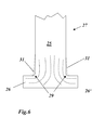
- the T-shaped blade roots 25 of the compressor blades 27 have been forged (forged) by upset forging so as to obtain a strength-determining grain structure as shown in FIG Fig. 6 is indicated by the dashed lines.
- the idea was not to forge the blade roots, but to make them by milling (grain structure in Fig. 4 ).
- the forging radius 29 is approximately in the range between 0.5 and 1.0 mm (FIG. Fig. 6 ). Due to the notch factor, milled blade feet at the transitions require a radius that is about 1.5 to 2 times greater than the forging radius 29.
- bulging 31 causes bulges 31 on the shaft above the projections 26, 26 '(in FIG Fig. 6 this is indicated by the dotted lines), which are in the range of 0.3 to 0.5 mm.
- bulging 31 causes bulges 31 on the shaft above the projections 26, 26 '(in FIG Fig. 6 this is indicated by the dotted lines), which are in the range of 0.3 to 0.5 mm.
- the object is solved by the entirety of the features of claims 1 and 8.
- Essential for the invention is that the T-shaped blade root is milled, and that in order to reduce the mechanical stresses at the transitions of the blade root to the projections in each case an axially extending undercut is provided.
- the compressor according to the invention has a rotor which is equipped with blades according to the invention.
- the undercut can be a standard undercut to ISO standard.
- the undercut is then an undercut type E or F according to DIN standard 506.
- the spacers each have a chamfer at their adjoining the blade root side surfaces
- the undercut has a deviating from a standard undercut to ISO standard, increased height, which the bevel exploits.
- the height of the undercut can correspond approximately to the height of the bevel.
- the undercut has a radius that is 1.5-2 times the radius of a comparable upset formed blade root.
- the radius is 1.5 mm with a compression radius of 0.8, or 1.75 mm with a compression radius of 1.0.
- the undercut follows an elliptical curve in the direction of the blade axis.
- a preferred embodiment of the method according to the invention is characterized in that the undercuts are milled in the direction of the blade axis along an elliptical processing path.
- Machining becomes particularly easy if a milling tool deviating from the spherical shape is used to mill the undercuts.
- undercut which is preferably realized taking into account the lateral bevels formed on the intermediate pieces.
- undercuts are first undercuts according to ISO standard in question, which are listed under the DIN standard 509 as undercuts form E and F.
- the undercut of type E only cuts into one of the two adjoining surfaces that are perpendicular to each other, while the undercut of type F cuts into both surfaces.
- Both undercut types have special outlet areas (32, 33 in Fig. 3 ), which serve the additional stress relief in the radius.
- the blades with forged blade root can be replaced by the cheaper blades with milled blade root without losses in the Lifetime must be accepted.
- the adjacent intermediate pieces 12, 18 need not be changed or additionally processed.
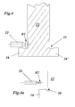
- the contact surface between the blade root (15 in Fig. 3 ) and the adjacent intermediate pieces 12 and 18 is limited by the chamfers 17 and 19 on the side surfaces of the intermediate pieces 12, 18, but also determined, so that the type of undercut 21 within the region of the chamfers 17, 19 has no influence on the contact surface ( Fig. 3 ). Accordingly, the blades are always held in the same way between the intermediate pieces 12, 18, regardless of whether the blade root is forged ( Fig. 6 ) or milled ( Fig. 4 ). It also follows that the natural frequencies (resonances) of the blades do not change, so that there is complete interchangeability between the differently manufactured blades.
- a standard undercut type F cuts - as already mentioned above - in both adjacent vertical surfaces in the corners of the projections 16, 16 'of the blade root 15 ( Fig. 4a ). This is the only way to achieve the increased radius for the desired equal or longer life over forged blade roots.
- a standard F-cut can only be produced by means of a milling process if the undercut is simultaneously moved in the direction of the blade axis A1 along an elliptical processing path (23 in FIG Fig. 5 ).
- the undercut can only be milled with a great deal of effort, since this is what the in Fig. 4a shown small milling tool 28 with a spherical milling head (head diameter (2 x radius R2): 2-3 mm, shank diameter: 1.5-2 mm) must be used.
- modified undercut 21 used, which is characterized by an increased height h in the direction of the longitudinal axis of the blade.
- the height h of the undercut 21 may correspond to the entire length of the chamfer 17, 19 on the side surfaces of the intermediate pieces 12, 18.
- the increase in the height h compared to the standard undercut 30 makes it possible, according to Fig. 4 to use a larger milling tool 22 with a radius R1> R2 (R1 is eg 1.75 mm), which significantly reduces costs and processing times (dashed hatch in Fig. 4 indicates that the blade root 15 is milled and not forged).
Landscapes
- Engineering & Computer Science (AREA)
- Mechanical Engineering (AREA)
- General Engineering & Computer Science (AREA)
- Structures Of Non-Positive Displacement Pumps (AREA)
- Turbine Rotor Nozzle Sealing (AREA)
Abstract
Description
- Die vorliegende Erfindung bezieht sich auf das Gebiet der Turbomaschinen. Sie betrifft eine Laufschaufel zur Befestigung am Rotor einer Turbomaschine, ein Verfahren zur Herstellung einer Laufschaufel, sowie einen Verdichter mit einer solchen Laufschaufel.
- Die Laufschaufeln eines Verdichters sind Teil eines axialen Verdichtersystems, das grosse Mengen von Luft bewegt und komprimiert, die zum ordnungsgemässen und sicheren Betrieb eines Gasturbinensystems benötigt werden. Die Laufschaufeln sind auf dem Aussenumfang des Rotors des Verdichters montiert und sind einer Vielzahl von mechanischen Belastungen ausgesetzt, die sich insbesondere auch nach der Art der Schaufelbefestigung richten.
- Um die für das System katastrophale Ablösung einer Laufschaufel vom Rotor sicher zu vermeiden, sind in der Vergangenheit unterschiedliche Systeme zur Befestigung der Laufschaufeln am Rotor entwickelt und vorgeschlagen worden. Eines dieser Systeme, auf welches sich die vorliegende Erfindung bezieht, ist das Befestigungssystem mit einem T-förmigen Schaufelfuss und Zwischenstücken, wie es in den
Fig. 1 und 2 bzw. inFig. 6 im Ausschnitt vereinfacht wiedergegeben ist, und dass seit langem beispielsweise aus der DruckschriftDE-PS-318 662 - Bei diesem System sind in einer um die Rotorachse (A2 in
Fig. 5 ) des Rotors 10 umlaufenden Nut 11 in Umfangsrichtung hintereinander Zwischenstücke 12, 18 eingesetzt und mittels an Hinterschneidungen 24 anliegenden Halteflächen 20 in der Nut 11 gehalten. Zwischen zwei benachbarten Zwischenstücken 12, 18 ist jeweils eine Laufschaufel 13 bzw. 27 angeordnet, die ein Schaufelblatt 14 umfasst und mit einem nach unten an das Schaufelblatt 14 anschliessenden T-förmigen Schaufelfuss 15 bzw. 25 (sieheFig. 6 ) an die Seitenflächen der angrenzenden Zwischenstücke 12, 18 anstösst und mit in Umfangsrichtung herausstehenden Vorsprüngen 16, 16' bzw. 26, 26' unter die benachbarten Zwischenstücke 12, 18 greift. Die Zwischenstücke 12, 18 und die Laufschaufeln 13 bzw. 27 sind dabei schräg zur Rotorachse A2 stehend angeordnet, so dass die Schaufelachse (A1 inFig. 5 ) mit der Rotorachse A2 einen Winkel von beispielsweise 25° einschliesst (sieheFig. 5 ). - Bisher sind die T-förmigen Schaufelfüsse 25 der Verdichter-Laufschaufeln 27 durch Stauchschmieden geformt (geschmiedet) worden und haben so eine die Festigkeit bestimmende Kornstruktur erhalten, wie sie in
Fig. 6 durch die gestrichelten Linien angedeutet ist. Neuerdings wird - bedingt durch neue Anforderungen hinsichtlich Kosten, Werkzeug und Logistik - zunehmend dazu übergegangen, die Schaufelfüsse nicht mehr zu schmieden, sondern durch Fräsen herzustellen (Kornstruktur inFig. 4 ). Um bei den gefrästen Schaufelfüssen an den kritischen Übergängen zu den Vorsprüngen 16, 16' bzw. 26, 26' dieselbe oder eine bessere Festigkeit zu erreichen, wie bei den geschmiedeten Schaufelfüssen, muss an den Übergängen ein grösserer Radius vorgesehen werden. Bei den geschmiedeten Schaufelfüssen 25 liegt der Schmiederadius 29 etwa im Bereich zwischen 0,5 und 1,0 mm (Fig. 6 ). Aufgrund des Kerbfaktors benötigen gefräste Schaufelfüsse an den Übergängen einen Radius, der etwa 1,5-bis 2-mal grösser ist, als der Schmiederadius 29. - Das bisherige Schmiedeverfahren für die Schaufelfüsse 25 hatte weitere Konsequenzen: Durch das Stauchschmieden kommt es zu Ausbauchungen 31 am Schaft oberhalb der Vorsprünge 26, 26' (in
Fig. 6 ist dies durch die punktierten Linien angedeutet), die im Bereich von 0,3 bis 0,5 mm liegen. Damit bei den montierten Laufschaufeln die geschmiedeten Schaufelfüsse 25 trotz der seitlichen Ausbauchungen 31 dennoch sicher und unverrückbar an den benachbarten Zwischenstücken 12, 18 anliegen, sind diese an den Seitenflächen im unteren Teil mit einer langen Abschrägung 17, 19 versehen, die Platz für die Ausbauchungen 31 schafft (siehe auchFig. 3 ). - Obgleich bereits ein von der Schaufelgrösse abhängender, 0,3 bis 0,5 mm breiter Spalt zwischen den angrenzenden Zwischenstücken 12, 18 und dem T-förmigen Schaufelfuss 25 besteht, würde eine Vergrösserung des Radius in den Ecken der Vorsprünge 26, 26' um den Faktor 1,5 bis 2 - wie sie für gefräste Schaufelfüsse notwendig ist - eine unerwünschte und gefährliche Kollision genau an der Stelle hervorrufen, wo eigentlich der Abbau mechanischer Spannungen das Ziel sein sollte.
- Es ist andererseits möglich, mechanische Spannungen in Bereichen von Maschinenteilen, in denen einerseits das Risiko von Rissen gross ist, andererseits der Raum für das Anbringen grösserer Radien jedoch beschränkt ist, dadurch abzubauen, dass dort geeignet dimensionierte und platzierte Freistiche nach ISO-Standard vorgesehen werden.
- Es ist Aufgabe der Erfindung, eine Laufschaufel mit T-förmigem Schaufelfuss der eingangs genannten Art in der Form so auszubilden, dass sie günstiger herstellbar ist und gleichwohl die für geschmiedete Schaufelfüsse übliche Lebensdauer erreicht, sowie ein Verfahren zu deren Herstellung anzugeben.
- Die Aufgabe wird durch die Gesamtheit der Merkmale der Ansprüche 1 und 8 gelöst. Wesentlich für die Erfindung ist, dass der T-förmige Schaufelfuss gefräst ist, und dass zur Verringerung der mechanischen Spannungen an den Übergängen des Schaufelfusses zu den Vorsprüngen jeweils ein in axialer Richtung verlaufender Freistich vorgesehen ist. Der erfindungsgemäss Verdichter weist einen Rotor auf, welcher mit Laufschaufeln gemäss der Erfindung bestückt ist.
- Grundsätzlich kann der Freistich ein Standard-Freistich nach ISO-Norm sein. Insbesondere ist der Freistich dann ein Freistich vom Typ E oder F gemäss DIN-Norm 506.
- Besonders vorteilhaft im Hinblick auf die Reduzierung der mechanischen Spannungen ist es, wenn die Zwischenstücke an ihren an den Schaufelfuss angrenzenden Seitenflächen jeweils eine Abschrägung aufweisen, und der Freistich ein von einem Standard-Freistich nach ISO-Norm abweichende, vergrösserte Höhe aufweist, welche die Abschrägung ausnutzt. Insbesondere kann dabei die Höhe des Freistichs in etwa der Höhe der Abschrägung entsprechen.
- Vorzugsweise weist der Freistich einen Radius auf, der dem 1,5-2-fachen des Radius eines vergleichbaren durch Stauchschmieden geformten Schaufelfusses entspricht. Insbesondere ist der Radius 1,5 mm bei einem Stauchradius von 0,8, bzw. 1,75 mm bei einem Stauchradius von 1,0.
- Weiterhin ist es vorteilhaft, wenn der Freistich in Richtung der Schaufelachse einem elliptischen Kurvenverlauf folgt.
- Eine bevorzugte Ausgestaltung des Verfahrens nach der Erfindung ist dadurch gekennzeichnet, dass die Freistiche in Richtung der Schaufelachse entlang eines elliptischen Bearbeitungspfades gefräst werden.
- Besonders einfach wird die Bearbeitung, wenn zum Fräsen der Freistiche ein von der Kugelform abweichendes Fräswerkzeug verwendet wird.
- Die Erfindung soll nachfolgend anhand von Ausführungsbeispielen im Zusammenhang mit der Zeichnung näher erläutert werden. Es zeigen
- Fig. 1
- in Umfangsrichtung gesehen die der Erfindung zugrunde liegende Befestigungsart der Laufschaufeln mit T-förmigem Schaufelfuss zwischen zwei Zwischenstücken;
- Fig. 2
- die Befestigungsart der
Fig. 1 in perspektivischer Darstellung; - Fig. 3
- die Ausgestaltung des Schaufelfusses gemäss einem Ausführungsbeispiel der Erfindung;
- Fig. 4
- die Bearbeitung des Freistichs am Schaufelfuss mit einem grösseren Fräswerkzeug gemäss einem Ausführungsbeispiel der Erfindung;
- Fig. 4a
- die Bearbeitung des Freistichs am Schaufelfuss mit einem kleineren Fräswerkzeug mit Kugelkopf;
- Fig. 5
- einen Schaufelfuss gemäss einem Ausführungsbeispiel der Erfindung in perspektivischer Darstellung mit einem eingezeichneten elliptischen Bearbeitungspfad; und
- Fig. 6
- den in herkömmlicher Weise durch Stauchschmieden hergestellten T-förmigen Schaufelfuss.
- Wesentlich für die vorliegende Erfindung ist, dass der für den gefrästen Schaufelfuss benötigte vergrösserte Radius durch einen Freistich erzeugt wird, der vorzugsweise unter Berücksichtigung der an den Zwischenstücken ausgebildeten seitlichen Abschrägungen verwirklicht wird. Als Freistiche kommen zunächst Freistiche nach ISO-Standard in Frage, die unter der DIN-Norm 509 als Freistiche der Form E und F aufgeführt sind. Der Freistich vom Typ E schneidet dabei nur in eine der beiden angrenzenden, zueinander senkrechten Flächen, während der Freistich vom Typ F in beide Flächen schneidet. Beide Freistich-Typen haben spezielle Auslaufbereiche (32, 33 in
Fig. 3 ), die dem zusätzlichen Spannungsabbau im Radius dienen. - Mit derartigen Freistichen wird erreicht, dass bei unveränderter Gesamtanordnung und Befestigungsart der Laufschaufeln ohne Probleme die Laufschaufeln mit geschmiedetem Schaufelfuss durch die kostengünstigeren Laufschaufeln mit gefrästem Schaufelfuss ersetzt werden können, ohne dass Einbussen in der Lebensdauer hingenommen werden müssen. Insbesondere müssen die angrenzenden Zwischenstücke 12, 18 nicht geändert oder zusätzlich bearbeitet werden. Die Kontaktfläche zwischen dem Schaufelfuss (15 in
Fig. 3 ) und den benachbarten Zwischenstücken 12 und 18 wird durch die Abschrägungen 17 und 19 an den Seitenflächen der Zwischenstücke 12, 18 begrenzt, aber auch bestimmt, so dass die Art des Freistichs 21 innerhalb des Bereichs der Abschrägungen 17, 19 keinen Einfluss auf die Kontaktfläche hat (Fig. 3 ). Entsprechend sind die Laufschaufeln immer in derselben Weise zwischen den Zwischenstücken 12, 18 gehalten, egal, ob der Schaufelfuss geschmiedet (Fig. 6 ) oder gefräst (Fig. 4 ) ist. Daraus folgt auch, dass sich die natürlichen Frequenzen (Resonanzen) der Schaufeln nicht ändern, so dass eine vollständige Austauschbarkeit zwischen den unterschiedlich hergestellten Schaufeln besteht. - Ein Standard-Freistich vom Typ F schneidet - wie bereits oben erwähnt - in beide angrenzenden senkrechten Flächen in den Ecken der Vorsprünge 16, 16' des Schaufelfusses 15 ein (
Fig. 4a ). Dies ist der einzige Weg, um den vergrösserten Radius für die gewünschte gleiche oder längere Lebensdauer gegenüber geschmiedeten Schaufelfüssen zu erzielen. Ein solcher Standard-F-Freistich kann jedoch nur mittels eines Fräsprozesses erzeugt werden, wenn der Freistich gleichzeitig in Richtung der Schaufelachse A1 entlang einem elliptischen Bearbeitungspfad (23 inFig. 5 ) erfolgen soll. Der Freistich ist jedoch nur mit sehr viel Aufwand zu fräsen, da hierfür das inFig. 4a dargestellte kleine Fräswerkzeug 28 mit einem kugelförmigen Fräskopf (Kopfdurchmesser (2 x Radius R2): 2-3 mm; Schaft-Durchmesser: 1,5-2 mm) benutzt werden muss. - Es wird daher beim Schaufelfuss 15 vorzugsweise der in
Fig. 3 ,4 und5 gezeigte modifizierte Freistich 21 eingesetzt, der sich durch eine vergrösserte Höhe h in Richtung der Längsachse der Schaufel auszeichnet. Insbesondere kann die Höhe h des Freistichs 21 der gesamten Länge der Abschrägung 17, 19 an den Seitenflächen der Zwischenstücke 12, 18 entsprechen. Die Vergrösserung der Höhe h gegenüber dem Standard-Freistich 30 ermöglicht es, gemässFig. 4 ein grösseres Fräswerkzeug 22 mit einem Radius R1 > R2 einzusetzen (R1 ist z.B. 1,75 mm), wodurch die Kosten und die Bearbeitungszeiten deutlich reduziert werden (die gestrichelte Schraffur inFig. 4 deutet an, dass der Schaufelfuss 15 gefräst und nicht geschmiedet ist). - Die beschriebene Vergrösserung der Höhe h des Freistichs ist nicht nur erlaubt (weil durch die lange Abschrägung 17, 19 ohnehin kein Kontakt zwischen Schaufelfuss 15 und den Zwischenstücken 12, 18 besteht), sondern auch erwünscht, weil die Spannungen in der Kerbe dadurch automatisch verringert werden.
-
- 10
- Rotor
- 11
- Nut
- 12,18
- Zwischenstück
- 13,27
- Laufschaufel
- 14
- Schaufelblatt
- 15,25
- Schaufelfuss
- 16,16'
- Vorsprung
- 17,19
- Abschrägung
- 20
- Haltefläche
- 21,30
- Freistich
- 22,28
- Fräswerkzeug
- 23
- elliptischer Bearbeitungspfad
- 24
- Hinterschneidung
- 26,26'
- Vorsprung
- 29
- Schmiederadius
- 31
- Ausbauchung
- 32,33
- Auslaufbereich
- A1
- Schaufelachse
- A2
- Rotorachse
- h
- Höhe (Freistich)
- R1,R2
- Radius (Freistich)
Claims (11)
- Laufschaufel (13) zur Befestigung am Rotor (10) einer Turbomaschine, insbesondere eines Verdichters einer Gasturbine, welche Laufschaufel (13) ein Schaufelblatt (14) und einen am unteren Ende des Schaufelblatts (14) anschliessenden, sich entlang einer Schaufelachse (A1) erstreckenden Schaufelfuss (15) umfasst, mit welchem die Laufschaufel (13) in einer auf dem Aussenumfang des Rotors (10) angeordneten umlaufenden Nut (11) zwischen zwei in Umfangsrichtung aufeinander folgenden Zwischenstücken (12, 18) gehalten wird, die ihrerseits in der Nut (11) gehalten werden, wobei der Schaufelfuss (15) im Querschnitt T-förmig ausgebildet ist und mit sich in Umfangsrichtung erstreckenden Vorsprüngen (16, 16') unter die angrenzenden Zwischenstücke (12, 18) greift, und die Zwischenstücke (12, 18) in Richtung der Schaufelachse (A1) mit Halteflächen (20) in Hinterschneidungen (24) in der Nut (11) eingreifen, dadurch gekennzeichnet, dass der T-förmige Schaufelfuss (15) gefräst ist, und dass zur Verringerung der mechanischen Spannungen an den Übergängen des Schaufelfusses (15) zu den Vorsprüngen (16, 16') jeweils ein in Richtung der Schaufelachse (A1) verlaufender Freistich (21, 30) vorgesehen ist.
- Laufschaufel nach Anspruch 1, dadurch gekennzeichnet, dass der Freistich (30) ein Standard-Freistich nach ISO-Norm ist.
- Laufschaufel nach Anspruch 2, dadurch gekennzeichnet, dass der Freistich (30) ein Freistich vom Typ E oder F gemäss DIN-Norm 506 ist.
- Laufschaufel nach Anspruch 1, dadurch gekennzeichnet, dass die Zwischenstücke (12, 18) an ihren an den Schaufelfuss (15) angrenzenden Seitenflächen jeweils eine Abschrägung (17, 19) aufweisen, und dass der Freistich (21) ein von einem Standard-Freistich nach ISO-Norm abweichende, vergrösserte Höhe (h) aufweist.
- Laufschaufel nach Anspruch 4, dadurch gekennzeichnet, dass die Höhe (h) des Freistichs (21) in etwa der Höhe der Abschrägung (17, 19) entspricht.
- Laufschaufel nach Anspruch 4 oder 5, dadurch gekennzeichnet, dass der Freistich (21) einen Radius (R1) aufweist, der dem 1,5-2-fachen des Radius eines vergleichbaren durch Stauchschmieden geformten Schaufelfusses entspricht.
- Laufschaufel nach einem der Ansprüche 1 bis 6, dadurch gekennzeichnet, dass der Freistich (21, 30) in Richtung der Schaufelachse (A1) einem elliptischen Kurvenverlauf (23) folgt.
- Verfahren zur Herstellung einer Laufschaufel nach einem der Ansprüche 1 bis 7, dadurch gekennzeichnet, dass in einem ersten Schritt die T-Form des Schaufelfusses (15) durch einen Fräsprozess erzeugt wird, und dass in einem zweiten Schritt die Freistiche (21, 30) in den Schaufelfuss (15) gefräst werden.
- Verfahren nach Anspruch 8, dadurch gekennzeichnet, dass die Freistiche (21, 30) in Richtung der Schaufelachse (A1) entlang eines elliptischen Bearbeitungspfades (23) gefräst werden.
- Verfahren nach Anspruch 8 oder 9, dadurch gekennzeichnet, dass zum Fräsen der Freistiche (21) ein von der Kugelform abweichendes Fräswerkzeug (22) verwendet wird.
- Verdichter, insbesondere für eine Gasturbine, dadurch gekennzeichnet, dass er einen Rotor (10) aufweist, welcher mit Laufschaufeln (13) gemäss einem der Ansprüche 1 bis 7 bestückt ist.
Applications Claiming Priority (1)
| Application Number | Priority Date | Filing Date | Title |
|---|---|---|---|
| CH15272007 | 2007-10-01 |
Publications (2)
| Publication Number | Publication Date |
|---|---|
| EP2045444A1 true EP2045444A1 (de) | 2009-04-08 |
| EP2045444B1 EP2045444B1 (de) | 2015-11-18 |
Family
ID=38896001
Family Applications (1)
| Application Number | Title | Priority Date | Filing Date |
|---|---|---|---|
| EP08165091.3A Active EP2045444B1 (de) | 2007-10-01 | 2008-09-25 | Laufschaufel, Verfahren zur Herstellung einer Laufschaufel, sowie Verdichter mit einer solchen Laufschaufel |
Country Status (4)
| Country | Link |
|---|---|
| US (1) | US8257047B2 (de) |
| EP (1) | EP2045444B1 (de) |
| JP (1) | JP2009085224A (de) |
| CA (1) | CA2640028C (de) |
Cited By (4)
| Publication number | Priority date | Publication date | Assignee | Title |
|---|---|---|---|---|
| CH702203A1 (de) * | 2009-11-10 | 2011-05-13 | Alstom Technology Ltd | Rotor für eine axial durchströmte turbomaschine sowie laufschaufel für einen solchen rotor. |
| DE102011082850A1 (de) * | 2011-09-16 | 2013-03-21 | Siemens Aktiengesellschaft | Verdichterschaufel und Verfahren zu ihrer Herstellung |
| US8770938B2 (en) | 2009-11-10 | 2014-07-08 | Alstom Technology Ltd | Rotor for an axial-throughflow turbomachine and moving blade for such a rotor |
| CN111571153A (zh) * | 2020-05-29 | 2020-08-25 | 重庆水轮机厂有限责任公司 | 一种转桨式水轮机桨叶叶型加工方法 |
Families Citing this family (14)
| Publication number | Priority date | Publication date | Assignee | Title |
|---|---|---|---|---|
| DE102010004854A1 (de) * | 2010-01-16 | 2011-07-21 | MTU Aero Engines GmbH, 80995 | Laufschaufel für eine Strömungsmaschine und Strömungsmaschine |
| CH704617A1 (de) * | 2011-03-07 | 2012-09-14 | Alstom Technology Ltd | Laufschaufelanordnung einer Strömungsmaschine. |
| FR2972380A1 (fr) * | 2011-03-11 | 2012-09-14 | Alstom Technology Ltd | Procede de fabrication d'un diaphragme de turbine a vapeur |
| CH704825A1 (de) | 2011-03-31 | 2012-10-15 | Alstom Technology Ltd | Turbomaschinenrotor. |
| CH705377A1 (de) * | 2011-08-09 | 2013-02-15 | Alstom Technology Ltd | Verfahren zur Rekonditionierung eines Rotors einer Strömungsmaschine. |
| US9359905B2 (en) | 2012-02-27 | 2016-06-07 | Solar Turbines Incorporated | Turbine engine rotor blade groove |
| GB2520203A (en) * | 2012-09-06 | 2015-05-13 | Solar Turbines Inc | Gas turbine engine compressor undercut spacer |
| US20140064946A1 (en) * | 2012-09-06 | 2014-03-06 | Solar Turbines Incorporated | Gas turbine engine compressor undercut spacer |
| US20140119821A1 (en) * | 2012-10-30 | 2014-05-01 | Jeffrey Lee Bertelsen | Insert slot and method of forming an insert slot in a rotary hand slip |
| EP2860361B1 (de) | 2013-10-08 | 2017-03-01 | MTU Aero Engines GmbH | Bauteilabstützung und Strömungsmaschine |
| US9739159B2 (en) | 2013-10-09 | 2017-08-22 | General Electric Company | Method and system for relieving turbine rotor blade dovetail stress |
| EP3015652A1 (de) * | 2014-10-28 | 2016-05-04 | Siemens Aktiengesellschaft | Laufschaufel für eine Turbine |
| CN116710660A (zh) * | 2021-04-22 | 2023-09-05 | 株式会社Ihi | 叶轮、离心压缩机以及叶轮的制造方法 |
| CN113914999B (zh) * | 2021-12-14 | 2022-03-18 | 成都中科翼能科技有限公司 | 一种燃气轮机压气机装配方法 |
Citations (10)
| Publication number | Priority date | Publication date | Assignee | Title |
|---|---|---|---|---|
| DE318662C (de) | 1918-02-18 | |||
| FR451147A (fr) * | 1912-11-28 | 1913-04-11 | Westinghouse Machine Co | Perfectionnements aux turbines à fluide sous pression |
| DE437049C (de) | 1923-01-19 | 1926-11-12 | Aeg | Verfahren zur Herstellung von Turbinenschaufeln |
| DE1005530B (de) * | 1955-06-23 | 1957-04-04 | Paul Miesbeck | Befestigung der Laufschaufeln von Kreiselmaschinen, insbesondere Dampf- und Gasturbinen |
| JPS59226202A (ja) * | 1983-06-06 | 1984-12-19 | Toshiba Corp | タ−ビン動翼 |
| EP0551229A1 (de) * | 1992-01-08 | 1993-07-14 | Gec Alsthom Sa | Trommelrotor für Impulsdampfturbine mit Schaufeln montiert in Längsnuten |
| DE4435268A1 (de) * | 1994-10-01 | 1996-04-04 | Abb Management Ag | Beschaufelter Rotor einer Turbomaschine |
| JP2005220825A (ja) | 2004-02-06 | 2005-08-18 | Mitsubishi Heavy Ind Ltd | タービン動翼 |
| EP1698758A2 (de) | 2005-02-23 | 2006-09-06 | ALSTOM Technology Ltd | Axial getrennter Rotor-Schluss |
| DE102005048883A1 (de) | 2005-10-12 | 2007-04-19 | Alstom Technology Ltd. | Turbinenschaufel und Turbinenlaufradbaugruppe |
Family Cites Families (4)
| Publication number | Priority date | Publication date | Assignee | Title |
|---|---|---|---|---|
| US2857132A (en) * | 1952-02-19 | 1958-10-21 | Gen Motors Corp | Turbine wheel |
| US4272953A (en) * | 1978-10-26 | 1981-06-16 | Rice Ivan G | Reheat gas turbine combined with steam turbine |
| JP3462695B2 (ja) * | 1997-03-12 | 2003-11-05 | 三菱重工業株式会社 | ガスタービン動翼シール板 |
| EP1130217B1 (de) * | 2000-03-01 | 2005-05-18 | ALSTOM Technology Ltd | Befestigung von Laufschaufeln in einer Turbomaschine |
-
2008
- 2008-09-25 EP EP08165091.3A patent/EP2045444B1/de active Active
- 2008-09-29 US US12/240,029 patent/US8257047B2/en active Active
- 2008-09-29 CA CA2640028A patent/CA2640028C/en not_active Expired - Fee Related
- 2008-10-01 JP JP2008256159A patent/JP2009085224A/ja not_active Withdrawn
Patent Citations (10)
| Publication number | Priority date | Publication date | Assignee | Title |
|---|---|---|---|---|
| FR451147A (fr) * | 1912-11-28 | 1913-04-11 | Westinghouse Machine Co | Perfectionnements aux turbines à fluide sous pression |
| DE318662C (de) | 1918-02-18 | |||
| DE437049C (de) | 1923-01-19 | 1926-11-12 | Aeg | Verfahren zur Herstellung von Turbinenschaufeln |
| DE1005530B (de) * | 1955-06-23 | 1957-04-04 | Paul Miesbeck | Befestigung der Laufschaufeln von Kreiselmaschinen, insbesondere Dampf- und Gasturbinen |
| JPS59226202A (ja) * | 1983-06-06 | 1984-12-19 | Toshiba Corp | タ−ビン動翼 |
| EP0551229A1 (de) * | 1992-01-08 | 1993-07-14 | Gec Alsthom Sa | Trommelrotor für Impulsdampfturbine mit Schaufeln montiert in Längsnuten |
| DE4435268A1 (de) * | 1994-10-01 | 1996-04-04 | Abb Management Ag | Beschaufelter Rotor einer Turbomaschine |
| JP2005220825A (ja) | 2004-02-06 | 2005-08-18 | Mitsubishi Heavy Ind Ltd | タービン動翼 |
| EP1698758A2 (de) | 2005-02-23 | 2006-09-06 | ALSTOM Technology Ltd | Axial getrennter Rotor-Schluss |
| DE102005048883A1 (de) | 2005-10-12 | 2007-04-19 | Alstom Technology Ltd. | Turbinenschaufel und Turbinenlaufradbaugruppe |
Cited By (4)
| Publication number | Priority date | Publication date | Assignee | Title |
|---|---|---|---|---|
| CH702203A1 (de) * | 2009-11-10 | 2011-05-13 | Alstom Technology Ltd | Rotor für eine axial durchströmte turbomaschine sowie laufschaufel für einen solchen rotor. |
| US8770938B2 (en) | 2009-11-10 | 2014-07-08 | Alstom Technology Ltd | Rotor for an axial-throughflow turbomachine and moving blade for such a rotor |
| DE102011082850A1 (de) * | 2011-09-16 | 2013-03-21 | Siemens Aktiengesellschaft | Verdichterschaufel und Verfahren zu ihrer Herstellung |
| CN111571153A (zh) * | 2020-05-29 | 2020-08-25 | 重庆水轮机厂有限责任公司 | 一种转桨式水轮机桨叶叶型加工方法 |
Also Published As
| Publication number | Publication date |
|---|---|
| JP2009085224A (ja) | 2009-04-23 |
| CA2640028C (en) | 2015-11-03 |
| CA2640028A1 (en) | 2009-04-01 |
| US20090087316A1 (en) | 2009-04-02 |
| US8257047B2 (en) | 2012-09-04 |
| EP2045444B1 (de) | 2015-11-18 |
Similar Documents
| Publication | Publication Date | Title |
|---|---|---|
| EP2045444B1 (de) | Laufschaufel, Verfahren zur Herstellung einer Laufschaufel, sowie Verdichter mit einer solchen Laufschaufel | |
| EP0906514B1 (de) | Rotor für eine turbomaschine mit in nuten anbringbaren schaufeln sowie schaufel für einen rotor | |
| DE69005845T2 (de) | Diaphragmaaufbau eines Verdichters. | |
| DE69105837T2 (de) | Gekühlte Turbinenschaufel. | |
| EP2376746B1 (de) | Deckbandsegment einer schaufel | |
| EP2882962B1 (de) | Rotorwelle für eine windturbine | |
| EP2378065B1 (de) | Verfahren zur Reparatur einer Rotoranordnung einer Turbomaschine. | |
| EP3999717B1 (de) | Zwischenelement für eine schaufel-rotorscheiben-verbindung bei einem rotor einer strömungsmaschine, rotor für eine strömungsmaschine und strömungsmaschine | |
| EP1174210A2 (de) | Verfahren und Rohling zum Herstellen von rhomboidischen Schaufeln für axiale Strömungsmaschinen | |
| EP1022439B1 (de) | Gehäuse für eine Dampf- oder eine Gasturbine | |
| WO1996013668A1 (de) | Radialverdichter oder radialturbine mit einem leitschaufeln aufweisenden diffusor oder turbinenleitkranz | |
| EP2410132B1 (de) | Verdichterschaufel eines Gasturbinentriebwerks mit selbstschärfender Vorderkantenstruktur | |
| EP2846000A2 (de) | Turbinenleitrad einer Gasturbine | |
| EP3287608B1 (de) | Innenring für einen leitschaufelkranz einer strömungsmaschine | |
| EP2394028A1 (de) | Abdichtvorrichtung an dem schaufelschaft einer rotorstufe einer axialen strömungsmaschine | |
| EP3176386B1 (de) | Innenringsystem, zugehöriger innenring, zwichengehäuse und strömungsmaschine | |
| EP3375986B1 (de) | Bauteil einer turbomaschine | |
| EP3628030B1 (de) | Verfahren zum instandhalten einer strömungsmaschine | |
| CH716176A2 (de) | Strömungsmaschine. | |
| EP3312388A1 (de) | Pultdach dichtfin | |
| EP3015652A1 (de) | Laufschaufel für eine Turbine | |
| WO2019105672A1 (de) | Laufschaufel einer strömungsmaschine und verfahren zum herstellen derselben | |
| DE102012216655A1 (de) | Drehantreibbares zerspanungswerkzeug | |
| EP3225789A1 (de) | Triebwerksbaugruppe mit fangehäuse und einlaufdiffusor | |
| DE102017216621A1 (de) | Rotor für einen Turbolader |
Legal Events
| Date | Code | Title | Description |
|---|---|---|---|
| PUAI | Public reference made under article 153(3) epc to a published international application that has entered the european phase |
Free format text: ORIGINAL CODE: 0009012 |
|
| AK | Designated contracting states |
Kind code of ref document: A1 Designated state(s): AT BE BG CH CY CZ DE DK EE ES FI FR GB GR HR HU IE IS IT LI LT LU LV MC MT NL NO PL PT RO SE SI SK TR |
|
| AX | Request for extension of the european patent |
Extension state: AL BA MK RS |
|
| 17P | Request for examination filed |
Effective date: 20091027 |
|
| AKX | Designation fees paid |
Designated state(s): AT BE BG CH CY CZ DE DK EE ES FI FR GB GR HR HU IE IS IT LI LT LU LV MC MT NL NO PL PT RO SE SI SK TR |
|
| 17Q | First examination report despatched |
Effective date: 20120329 |
|
| GRAP | Despatch of communication of intention to grant a patent |
Free format text: ORIGINAL CODE: EPIDOSNIGR1 |
|
| INTG | Intention to grant announced |
Effective date: 20150701 |
|
| GRAS | Grant fee paid |
Free format text: ORIGINAL CODE: EPIDOSNIGR3 |
|
| GRAA | (expected) grant |
Free format text: ORIGINAL CODE: 0009210 |
|
| AK | Designated contracting states |
Kind code of ref document: B1 Designated state(s): AT BE BG CH CY CZ DE DK EE ES FI FR GB GR HR HU IE IS IT LI LT LU LV MC MT NL NO PL PT RO SE SI SK TR |
|
| REG | Reference to a national code |
Ref country code: GB Ref legal event code: FG4D Free format text: NOT ENGLISH |
|
| REG | Reference to a national code |
Ref country code: CH Ref legal event code: EP |
|
| REG | Reference to a national code |
Ref country code: AT Ref legal event code: REF Ref document number: 761693 Country of ref document: AT Kind code of ref document: T Effective date: 20151215 |
|
| REG | Reference to a national code |
Ref country code: IE Ref legal event code: FG4D Free format text: LANGUAGE OF EP DOCUMENT: GERMAN |
|
| REG | Reference to a national code |
Ref country code: DE Ref legal event code: R096 Ref document number: 502008013592 Country of ref document: DE |
|
| REG | Reference to a national code |
Ref country code: NL Ref legal event code: MP Effective date: 20160218 |
|
| REG | Reference to a national code |
Ref country code: LT Ref legal event code: MG4D |
|
| PG25 | Lapsed in a contracting state [announced via postgrant information from national office to epo] |
Ref country code: NO Free format text: LAPSE BECAUSE OF FAILURE TO SUBMIT A TRANSLATION OF THE DESCRIPTION OR TO PAY THE FEE WITHIN THE PRESCRIBED TIME-LIMIT Effective date: 20160218 Ref country code: IT Free format text: LAPSE BECAUSE OF FAILURE TO SUBMIT A TRANSLATION OF THE DESCRIPTION OR TO PAY THE FEE WITHIN THE PRESCRIBED TIME-LIMIT Effective date: 20151118 Ref country code: LT Free format text: LAPSE BECAUSE OF FAILURE TO SUBMIT A TRANSLATION OF THE DESCRIPTION OR TO PAY THE FEE WITHIN THE PRESCRIBED TIME-LIMIT Effective date: 20151118 Ref country code: ES Free format text: LAPSE BECAUSE OF FAILURE TO SUBMIT A TRANSLATION OF THE DESCRIPTION OR TO PAY THE FEE WITHIN THE PRESCRIBED TIME-LIMIT Effective date: 20151118 Ref country code: NL Free format text: LAPSE BECAUSE OF FAILURE TO SUBMIT A TRANSLATION OF THE DESCRIPTION OR TO PAY THE FEE WITHIN THE PRESCRIBED TIME-LIMIT Effective date: 20151118 Ref country code: HR Free format text: LAPSE BECAUSE OF FAILURE TO SUBMIT A TRANSLATION OF THE DESCRIPTION OR TO PAY THE FEE WITHIN THE PRESCRIBED TIME-LIMIT Effective date: 20151118 Ref country code: IS Free format text: LAPSE BECAUSE OF FAILURE TO SUBMIT A TRANSLATION OF THE DESCRIPTION OR TO PAY THE FEE WITHIN THE PRESCRIBED TIME-LIMIT Effective date: 20160318 |
|
| PG25 | Lapsed in a contracting state [announced via postgrant information from national office to epo] |
Ref country code: LV Free format text: LAPSE BECAUSE OF FAILURE TO SUBMIT A TRANSLATION OF THE DESCRIPTION OR TO PAY THE FEE WITHIN THE PRESCRIBED TIME-LIMIT Effective date: 20151118 Ref country code: PT Free format text: LAPSE BECAUSE OF FAILURE TO SUBMIT A TRANSLATION OF THE DESCRIPTION OR TO PAY THE FEE WITHIN THE PRESCRIBED TIME-LIMIT Effective date: 20160318 Ref country code: GR Free format text: LAPSE BECAUSE OF FAILURE TO SUBMIT A TRANSLATION OF THE DESCRIPTION OR TO PAY THE FEE WITHIN THE PRESCRIBED TIME-LIMIT Effective date: 20160219 Ref country code: FI Free format text: LAPSE BECAUSE OF FAILURE TO SUBMIT A TRANSLATION OF THE DESCRIPTION OR TO PAY THE FEE WITHIN THE PRESCRIBED TIME-LIMIT Effective date: 20151118 Ref country code: PL Free format text: LAPSE BECAUSE OF FAILURE TO SUBMIT A TRANSLATION OF THE DESCRIPTION OR TO PAY THE FEE WITHIN THE PRESCRIBED TIME-LIMIT Effective date: 20151118 Ref country code: SE Free format text: LAPSE BECAUSE OF FAILURE TO SUBMIT A TRANSLATION OF THE DESCRIPTION OR TO PAY THE FEE WITHIN THE PRESCRIBED TIME-LIMIT Effective date: 20151118 |
|
| REG | Reference to a national code |
Ref country code: CH Ref legal event code: PFA Owner name: GENERAL ELECTRIC TECHNOLOGY GMBH, CH Free format text: FORMER OWNER: ALSTOM TECHNOLOGY LTD, CH |
|
| PG25 | Lapsed in a contracting state [announced via postgrant information from national office to epo] |
Ref country code: CZ Free format text: LAPSE BECAUSE OF FAILURE TO SUBMIT A TRANSLATION OF THE DESCRIPTION OR TO PAY THE FEE WITHIN THE PRESCRIBED TIME-LIMIT Effective date: 20151118 |
|
| RAP2 | Party data changed (patent owner data changed or rights of a patent transferred) |
Owner name: GENERAL ELECTRIC TECHNOLOGY GMBH |
|
| REG | Reference to a national code |
Ref country code: DE Ref legal event code: R097 Ref document number: 502008013592 Country of ref document: DE |
|
| PG25 | Lapsed in a contracting state [announced via postgrant information from national office to epo] |
Ref country code: RO Free format text: LAPSE BECAUSE OF FAILURE TO SUBMIT A TRANSLATION OF THE DESCRIPTION OR TO PAY THE FEE WITHIN THE PRESCRIBED TIME-LIMIT Effective date: 20151118 Ref country code: EE Free format text: LAPSE BECAUSE OF FAILURE TO SUBMIT A TRANSLATION OF THE DESCRIPTION OR TO PAY THE FEE WITHIN THE PRESCRIBED TIME-LIMIT Effective date: 20151118 Ref country code: SK Free format text: LAPSE BECAUSE OF FAILURE TO SUBMIT A TRANSLATION OF THE DESCRIPTION OR TO PAY THE FEE WITHIN THE PRESCRIBED TIME-LIMIT Effective date: 20151118 Ref country code: DK Free format text: LAPSE BECAUSE OF FAILURE TO SUBMIT A TRANSLATION OF THE DESCRIPTION OR TO PAY THE FEE WITHIN THE PRESCRIBED TIME-LIMIT Effective date: 20151118 |
|
| PLBE | No opposition filed within time limit |
Free format text: ORIGINAL CODE: 0009261 |
|
| STAA | Information on the status of an ep patent application or granted ep patent |
Free format text: STATUS: NO OPPOSITION FILED WITHIN TIME LIMIT |
|
| REG | Reference to a national code |
Ref country code: DE Ref legal event code: R082 Ref document number: 502008013592 Country of ref document: DE Representative=s name: RUEGER | ABEL PATENT- UND RECHTSANWAELTE, DE Ref country code: DE Ref legal event code: R082 Ref document number: 502008013592 Country of ref document: DE Representative=s name: RUEGER ABEL PATENTANWAELTE PARTGMBB, DE Ref country code: DE Ref legal event code: R082 Ref document number: 502008013592 Country of ref document: DE Representative=s name: RUEGER, BARTHELT & ABEL, DE Ref country code: DE Ref legal event code: R081 Ref document number: 502008013592 Country of ref document: DE Owner name: GENERAL ELECTRIC TECHNOLOGY GMBH, CH Free format text: FORMER OWNER: ALSTOM TECHNOLOGY LTD., BADEN, CH Ref country code: DE Ref legal event code: R082 Ref document number: 502008013592 Country of ref document: DE Representative=s name: RUEGER ABEL PATENT- UND RECHTSANWAELTE, DE |
|
| 26N | No opposition filed |
Effective date: 20160819 |
|
| PGFP | Annual fee paid to national office [announced via postgrant information from national office to epo] |
Ref country code: CH Payment date: 20160927 Year of fee payment: 9 |
|
| PG25 | Lapsed in a contracting state [announced via postgrant information from national office to epo] |
Ref country code: SI Free format text: LAPSE BECAUSE OF FAILURE TO SUBMIT A TRANSLATION OF THE DESCRIPTION OR TO PAY THE FEE WITHIN THE PRESCRIBED TIME-LIMIT Effective date: 20151118 |
|
| PG25 | Lapsed in a contracting state [announced via postgrant information from national office to epo] |
Ref country code: BE Free format text: LAPSE BECAUSE OF NON-PAYMENT OF DUE FEES Effective date: 20160930 |
|
| PG25 | Lapsed in a contracting state [announced via postgrant information from national office to epo] |
Ref country code: MC Free format text: LAPSE BECAUSE OF FAILURE TO SUBMIT A TRANSLATION OF THE DESCRIPTION OR TO PAY THE FEE WITHIN THE PRESCRIBED TIME-LIMIT Effective date: 20151118 |
|
| GBPC | Gb: european patent ceased through non-payment of renewal fee |
Effective date: 20160925 |
|
| REG | Reference to a national code |
Ref country code: IE Ref legal event code: MM4A |
|
| REG | Reference to a national code |
Ref country code: FR Ref legal event code: ST Effective date: 20170531 |
|
| PG25 | Lapsed in a contracting state [announced via postgrant information from national office to epo] |
Ref country code: IE Free format text: LAPSE BECAUSE OF NON-PAYMENT OF DUE FEES Effective date: 20160925 Ref country code: GB Free format text: LAPSE BECAUSE OF NON-PAYMENT OF DUE FEES Effective date: 20160925 Ref country code: FR Free format text: LAPSE BECAUSE OF NON-PAYMENT OF DUE FEES Effective date: 20160930 |
|
| PG25 | Lapsed in a contracting state [announced via postgrant information from national office to epo] |
Ref country code: LU Free format text: LAPSE BECAUSE OF NON-PAYMENT OF DUE FEES Effective date: 20160925 |
|
| REG | Reference to a national code |
Ref country code: AT Ref legal event code: MM01 Ref document number: 761693 Country of ref document: AT Kind code of ref document: T Effective date: 20160925 |
|
| REG | Reference to a national code |
Ref country code: BE Ref legal event code: MM Effective date: 20160930 |
|
| PG25 | Lapsed in a contracting state [announced via postgrant information from national office to epo] |
Ref country code: AT Free format text: LAPSE BECAUSE OF NON-PAYMENT OF DUE FEES Effective date: 20160925 |
|
| REG | Reference to a national code |
Ref country code: CH Ref legal event code: PL |
|
| PG25 | Lapsed in a contracting state [announced via postgrant information from national office to epo] |
Ref country code: HU Free format text: LAPSE BECAUSE OF FAILURE TO SUBMIT A TRANSLATION OF THE DESCRIPTION OR TO PAY THE FEE WITHIN THE PRESCRIBED TIME-LIMIT; INVALID AB INITIO Effective date: 20080925 Ref country code: CY Free format text: LAPSE BECAUSE OF FAILURE TO SUBMIT A TRANSLATION OF THE DESCRIPTION OR TO PAY THE FEE WITHIN THE PRESCRIBED TIME-LIMIT Effective date: 20151118 |
|
| PG25 | Lapsed in a contracting state [announced via postgrant information from national office to epo] |
Ref country code: TR Free format text: LAPSE BECAUSE OF FAILURE TO SUBMIT A TRANSLATION OF THE DESCRIPTION OR TO PAY THE FEE WITHIN THE PRESCRIBED TIME-LIMIT Effective date: 20151118 Ref country code: MT Free format text: LAPSE BECAUSE OF FAILURE TO SUBMIT A TRANSLATION OF THE DESCRIPTION OR TO PAY THE FEE WITHIN THE PRESCRIBED TIME-LIMIT Effective date: 20151118 |
|
| PG25 | Lapsed in a contracting state [announced via postgrant information from national office to epo] |
Ref country code: BG Free format text: LAPSE BECAUSE OF FAILURE TO SUBMIT A TRANSLATION OF THE DESCRIPTION OR TO PAY THE FEE WITHIN THE PRESCRIBED TIME-LIMIT Effective date: 20151118 Ref country code: LI Free format text: LAPSE BECAUSE OF NON-PAYMENT OF DUE FEES Effective date: 20170930 Ref country code: CH Free format text: LAPSE BECAUSE OF NON-PAYMENT OF DUE FEES Effective date: 20170930 |
|
| P01 | Opt-out of the competence of the unified patent court (upc) registered |
Effective date: 20230522 |
|
| PGFP | Annual fee paid to national office [announced via postgrant information from national office to epo] |
Ref country code: DE Payment date: 20250820 Year of fee payment: 18 |