EP2045405A1 - Betätigungsplatte für eine Betätigungsvorrichtung einer Spüleinrichtung - Google Patents
Betätigungsplatte für eine Betätigungsvorrichtung einer Spüleinrichtung Download PDFInfo
- Publication number
- EP2045405A1 EP2045405A1 EP07405297A EP07405297A EP2045405A1 EP 2045405 A1 EP2045405 A1 EP 2045405A1 EP 07405297 A EP07405297 A EP 07405297A EP 07405297 A EP07405297 A EP 07405297A EP 2045405 A1 EP2045405 A1 EP 2045405A1
- Authority
- EP
- European Patent Office
- Prior art keywords
- actuating
- plate
- spring
- spring element
- bearing
- Prior art date
- Legal status (The legal status is an assumption and is not a legal conclusion. Google has not performed a legal analysis and makes no representation as to the accuracy of the status listed.)
- Granted
Links
Images


Classifications
-
- E—FIXED CONSTRUCTIONS
- E03—WATER SUPPLY; SEWERAGE
- E03D—WATER-CLOSETS OR URINALS WITH FLUSHING DEVICES; FLUSHING VALVES THEREFOR
- E03D5/00—Special constructions of flushing devices, e.g. closed flushing system
- E03D5/02—Special constructions of flushing devices, e.g. closed flushing system operated mechanically or hydraulically (or pneumatically) also details such as push buttons, levers and pull-card therefor
- E03D5/09—Special constructions of flushing devices, e.g. closed flushing system operated mechanically or hydraulically (or pneumatically) also details such as push buttons, levers and pull-card therefor directly by the hand
-
- E—FIXED CONSTRUCTIONS
- E03—WATER SUPPLY; SEWERAGE
- E03D—WATER-CLOSETS OR URINALS WITH FLUSHING DEVICES; FLUSHING VALVES THEREFOR
- E03D5/00—Special constructions of flushing devices, e.g. closed flushing system
- E03D5/02—Special constructions of flushing devices, e.g. closed flushing system operated mechanically or hydraulically (or pneumatically) also details such as push buttons, levers and pull-card therefor
- E03D5/028—Pusher plates and actuating mechanisms for built-in cisterns
Definitions
- the invention relates to an actuating plate for an actuating device of a flushing device, comprising a bearing plate which has a bearing on a rear side, on which at least one actuating element for a flushing release is pivotably mounted.
- An actuator plate of this type is known in the art from EP 1 795 662A have become known to the applicant.
- a bearing block is formed on the back, on which a key is mounted, which is pivotable on a front side of the bearing plate by hand against a return spring.
- a pusher press fitted to the button is moved downwards.
- This pusher rod pivots an actuating lever, which thereby raises a closure body of a drain valve and thus opens the valve. After the flushing process, the closure body lowers again on the valve seat and the pusher rod and the key go back to the starting position.
- the invention is based on the object to provide an actuator plate of the type mentioned, which is manufactured much cheaper and yet reliable.
- the object is achieved according to claim 1 in a generic actuator plate characterized in that the bearing is formed by at least one spring element which is connected at a first end to the bearing plate and a second end to the at least one actuating element.
- the hitherto additional spring element now forms a joint in the inventive actuating plate, with which the actuating element limited pivotable with the bearing plate connected is. This eliminates a separate spring element, which allows a substantial reduction in manufacturing costs.
- a significant advantage of the inventive actuator plate is also that the connection of the button with the bearing plate on the spring element allows a substantially backlash-free storage of the button.
- the actuator plate can thus be manufactured with smaller tolerances.
- it has been shown that the actuator plate can also be made with smaller deformations. Overall, this results in a more cost-effective production and higher reliability.
- the at least one spring element between said two ends has a constriction or is softer elastic between these ends than at these ends.
- the spring element can thereby be made comparatively firm and largely inelastic at the ends.
- the attachment of these ends can be made very stable. Nevertheless, by the constriction between the ends or the soft elastic training elastic deflection with relatively little effort possible. Such a constriction can be achieved very easily and inexpensively in particular by a sidecut of the spring element.
- the at least one spring element is a leaf spring.
- a leaf spring can on the one hand be produced very cost-effectively as a stamped part and on the other hand can be stably fixed at their ends to the bearing plate or to the key.
- the leaf spring made of metal, in particular made of spring steel.
- the at least one spring element at the first end with openings fixed to the bearing plate and at the second end with further openings fixedly connected to the at least one actuating element.
- These breakthroughs allow a very secure and solid or positive connection, for example, in which the spring element is attached to these openings with rivets.
- These rivets are hot rivets according to a development of the invention. These hot rivets are preferably molded plastic parts, which protrude through said openings. This allows a very cost effective and automatic production.
- the apertures or rivets are non-circular in cross section.
- a particularly reliable and stable storage of at least one key is obtained when it is mounted with two spaced-apart spring elements.
- the at least one spring element attached to the bearing plate on a pedestal. The corresponding end is thus arranged slightly elevated with respect to the back of the bearing plate. This deformation of the bearing plate can be largely avoided.
- the at least one spring element is biased so that the at least one actuating element is positioned in a starting position against a stop. This can be achieved that the actuating element always assumes the exact starting position.
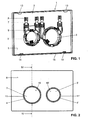
- the actuating plate 1 has a bearing plate 2, which has a front side 6 and a rear side 5.
- a peripheral edge 15 projects beyond the back 5 and has tabs 13 and 14, with which it can be fastened to a frame, not shown here, for example, in a. Inspection opening of a cistern is used.
- the bearing plate 2 can be mounted in a horizontal or vertical plane. It can for example be made of plastic by injection molding.
- the actuator plate 1 has two keys 3 and 3 ', which are arranged in a respective ring 11 and 11', which are respectively inserted into an opening 4 and 4 '. These keys 3 and 3 'each have front a tact surface 16 or 16', which are each substantially flush with the front side 6 of the bearing plate 2. By pressing on these tactile surfaces 16 and 16 ', the corresponding key 3 or 3' pivots and thereby a rinse be triggered. This pivoting movement is by a in the FIGS. 3 and 4 shown limited stop 12, which is integrally formed on the back of the bearing plate 2. For example, here a presser bar is moved, which rests on the back of the button 3 or 3 '.
- buttons 3 and 3 ' show an actuator plate 1 with only one button.
- the keys 3 and 3 'shown are circular as shown. But there are other forms conceivable here.
- the keys 3 and 3 ' can also be out of round, for example oval or angular.
- the keys 3 and 3 ' are each connected with two spring elements 7 hingedly connected to the bearing plate 2.
- These spring elements 7 are preferably leaf springs and made of a resilient material, such as steel and spring steel in particular. In principle, however, other elastic materials are also conceivable here.
- the spring elements 7 each have a first end 7b, which is connected to the bearing plate 2 and a second end 7c, which is connected to one of the keys 3 and 3 '.
- the first end 7b is mounted on a base 8 which is arranged on the back 5 of the bearing plate 2 and fixedly connected thereto.
- the base 8 is formed, for example, on the bearing plate 2.
- the first end 7b is thus arranged at a distance from the back 5 of the bearing plate 2.
- the base 8 stabilizes the bearing plate 2 in the region of the first end 7b and in particular prevents the bearing plate 2 from being deformed during production.
- the connection between the base 8 and the first end 7b is preferably fixed and in particular insoluble.
- the connection is a riveted joint in the embodiment shown.
- the connection is thus form-fitting.
- the first end 7b has two recesses 7d, through each of which a rivet 10 protrudes.
- These rivets 10 are in particular hot rivets made of plastic which have been shaped by appropriate heat. As can be seen, these rivets 10 and the corresponding recesses 7d are preferably non-circular.
- each key 3 or 3 ' has two arms 9, each extending at a distance and parallel to each other.
- the ends 7b and 7c each have a turn 7e at opposite edges.
- the springs 7 each have a constriction 7a. The springs 7 are thus fitted between these ends, in particular the FIG. 5 shows. By this constriction 7a or sidecut the spring elements 7 at the ends 7b and 7c can be made wider and thus more rigid.
- the springs 7 When pivoting the keys 3 and 3 ', the springs 7 are thus deformed elastically substantially exclusively between the two ends 7b and 7c in the region of the constriction 7a.
- the ends 7b and 7c in this case remain substantially rigidly connected to the base 8 or to the arm 9.
- the area between the ends 7b and 7c could also be made more flexible than at these ends.
- the spring elements 7 are slightly biased so that they hold the button 3 or 3 'in the intended starting position. This starting position can be defined by corresponding stops. Upon actuation, the key 3 becomes FIG. 4 pivoted in the direction of the arrow 16 against the retroactive force of the corresponding spring elements. As already explained above, these spring elements 7 are elastically deformed in the region of the constriction 7a. If the corresponding button 3 is released, it goes back into the in due to the spring force of the spring elements 7 automatically FIG. 4 shown starting position back.
- the spring elements 7 allow a largely play-free storage of the keys 3 and 3 '. The keys 3 and 3 'go back to an exact position by pressing an operation. Due to the small number of items, the inventive actuator plate 1 can be made very inexpensive.
Landscapes
- Engineering & Computer Science (AREA)
- Mechanical Engineering (AREA)
- Aviation & Aerospace Engineering (AREA)
- Health & Medical Sciences (AREA)
- Life Sciences & Earth Sciences (AREA)
- Hydrology & Water Resources (AREA)
- Public Health (AREA)
- Water Supply & Treatment (AREA)
- Holders For Apparel And Elements Relating To Apparel (AREA)
- Hinge Accessories (AREA)
- Slide Fasteners, Snap Fasteners, And Hook Fasteners (AREA)
Abstract
Description
- Die Erfindung betrifft eine Betätigungsplatte für eine Betätigungvorrichtung einer Spüleinrichtung, mit einer Lagerplatte, die an einer Rückseite ein Lager aufweist, an dem wenigstens ein Betätigungselement für eine Spülauslösung schwenkbar gelagert ist.
- Eine Betätigungsplatte dieser Art ist im Stand der Technik aus der
EP 1 795 662A des Anmelders bekannt geworden. Bei dieser ist an der Rückseite ein Lagerbock angeformt, an dem eine Taste gelagert ist, die an einer Frontseite der Lagerplatte von Hand gegen eine Rückstellfeder verschwenkbar ist. Beim Verschwenken wird eine an der Taste anliegende Drückerstange nach unten bewegt. Diese Drückerstange verschwenkt einen Betätigungshebel, der dadurch einen Verschlusskörper eines Ablaufventils anhebt und damit das Ventil öffnet. Nach dem Spülvorgang senkt sich der Verschlusskörper wieder auf dem Ventilsitz und die Drückerstange sowie die Taste gehen wieder in die Ausgangsstellung zurück. - Der Erfindung liegt die Aufgabe zu Grunde, eine Betätigungsplatte der genannten Art zu schaffen, die wesentlich kostengünstiger hergestellt und dennoch funktionssicher ist.
- Die Aufgabe ist gemäss Anspruch 1 bei einer gattungsgemässen Betätigungsplatte dadurch gelöst, dass das Lager durch wenigstens ein Federelement gebildet wird, das an einem ersten Ende mit der Lagerplatte und mit einem zweiten Ende mit dem wenigstens einen Betätigungselement verbunden ist. Das bisher zusätzliche Federelement bildet nun bei der erfindungsgemässen Betätigungsplatte ein Gelenk, mit dem das Betätigungselement begrenzt verschwenkbar mit der Lagerplatte verbunden ist. Dadurch erübrigt sich ein separates Federelement, was eine wesentliche Reduktion der Herstellungskosten ermöglicht. Ein wesentlicher Vorteil der erfindungsgemässen Betätigungsplatte besteht auch darin, dass die Verbindung der Taste mit der Lagerplatte über das Federelement eine im wesentlichen spielfreie Lagerung der Taste ermöglicht. Die Betätigungsplatte kann somit mit kleineren Toleranzen hergestellt werden. Zudem hat sich gezeigt, dass die Betätigungsplatte zudem mit kleineren Verformungen hergestellt werden kann. Insgesamt ergibt sich damit eine kostengünstigere Herstellung und eine höhere Funktionssicherheit.
- Nach einer Weiterbildung der Erfindung ist vorgesehen, dass das wenigstens eine Federelement zwischen den genannten beiden Enden eine Einschnürung aufweist oder zwischen diesen Enden weichelastischer ist als an diesen Enden. Das Federelement kann dadurch an den Enden vergleichsweise fest und weitgehend unelastisch ausgebildet werden. Die Befestigung dieser Enden kann dadurch sehr stabil ausgebildet werden. Dennoch ist durch die Einschnürung zwischen den Enden bzw. der weichelastischeren Ausbildung eine elastische Auslenkung mit vergleichsweise geringem Kraftaufwand möglich. Eine solche Einschnürung kann insbesondere durch eine Taillierung des Federelementes sehr einfach und kostengünstig erreicht werden.
- Nach einer Weiterbildung der Erfindung ist das wenigstens eine Federelement eine Blattfeder. Eine solche Blattfeder kann einerseits sehr kostengünstig als Stanzteil hergestellt werden und lässt sich andererseits an ihren Enden an der Lagerplatte bzw. an der Taste stabil befestigen. Vorzugsweise ist die Blattfeder aus Metall, insbesondere aus Federstahl hergestellt.
- Nach einer Weiterbildung der Erfindung ist das wenigstens eine Federelement am ersten Ende mit Durchbrüchen fest mit der Lagerplatte und am zweiten Ende mit weiteren Durchbrüchen fest mit dem wenigstens einen Betätigungselement verbunden. Diese Durchbrüche ermöglichen eine sehr sichere und feste bzw. formschlüssige Verbindung, beispielsweise in dem das Federelement an diesen Durchbrüchen mit Nieten befestigt wird. Diese Nieten sind nach einer Weiterbildung der Erfindung Heissnieten. Diese Heissnieten sind vorzugsweise angeformte Kunststoffteile, welche durch die genannten Durchbrüche hindurchragen. Dies ermöglicht eine sehr kostengünstige und automatische Fertigung. Vorzugsweise sind die Durchbrüche bzw. die Nieten im Querschnitt unrund.
- Eine besonders funktionssichere und stabile Lagerung der wenigstens eine Taste ergibt sich dann, wenn diese mit zwei im Abstand zu einander angeordneten Federelementen gelagert ist. Nach einer Weiterbildung der Erfindung ist das wenigstens eine Federelement an der Lagerplatte auf einem Sockel befestigt. Das entsprechende Ende ist somit bezüglich der Rückseite der Lagerplatte etwas erhöht angeordnet. Damit können Deformationen an der Lagerplatte weitgehend vermieden werden.
- Nach einer Weiterbildung der Erfindung ist das wenigstens eine Federelement so vorgespannt, dass das wenigstens eine Betätigungselement in einer Ausgangsposition gegen einen Anschlag positioniert ist. Damit kann erreicht werden, dass das Betätigungselement immer besonders exakt die Ausgangsposition einnimmt.
- Weitere vorteilhafte Merkmale ergeben sich aus den abhängigen Patentansprüchen, der nachfolgenden Beschreibung sowie der Zeichnung.
- Ein Ausführungsbeispiel der Erfindung wird nachfolgend anhand der Zeichnung näher erläutert. Es zeigen:
- Figur 1
- eine räumliche Ansicht von der Rückseite der erfindungsgemässen Betätigungsplatte,
- Figur 2
- eine Ansicht der Frontseite der erfindungsgemässen Betätigungsplatte,
- Figur 3
- eine Seitenansicht der erfindungsgemässen Betätigungsplatte,
- Figur 4
- ein Schnitt entlang der Linie IV - IV der
Figur 2 und - Figur 5
- eine räumliche Detailansicht der erfindungsgemässen Betätigungsplatte
- Die Betätigungsplatte 1 weist eine Lagerplatte 2 auf, die eine Frontseite 6 sowie eine Rückseite 5 besitzt. Ein umlaufender Rand 15 übersteht die Rückseite 5 und besitzt Laschen 13 und 14, mit denen sie an einem hier nicht gezeigten Rahmen befestigbar ist, der beispielsweise in einer . Revisionsöffnung eines Spülkastens eingesetzt ist. Die Lagerplatte 2 kann in einer horizontalen oder auch vertikalen Ebene montiert werden. Sie kann beispielsweise aus Kunststoff im Spritzgussverfahren hergestellt werden.
- Die Betätigungsplatte 1 besitzt zwei Tasten 3 und 3', die in jeweils einem Ring 11 bzw. 11' angeordnet sind, die jeweils in eine Öffnung 4 bzw. 4' eingesetzt sind. Diese Tasten 3 und 3' besitzen jeweils frontseitig eine Tastfläche 16 bzw. 16', die jeweils im Wesentlichen bündig sind mit der Frontseite 6 der Lagerplatte 2. Durch Druck auf diese Tastflächen 16 und 16' kann die entsprechende Taste 3 bzw. 3' verschwenkt und dadurch eine Spülung ausgelöst werden. Diese Schwenkbewegung ist durch einen in den
Figuren 3 und 4 gezeigten Anschlag 12 begrenzt, der an der Rückseite der Lagerplatte 2 angeformt ist. Beispielsweise wird hier eine Drückerstange bewegt, die an der Rückseite der Taste 3 bzw. 3' anliegt. Mit der Taste 3 kann eine Vollspülung und mit der kleiner Taste 3' eine Teilspülung ausgelöst werden. Denkbar ist aber auch eine Betätigungsplatte 1 mit lediglich einer Taste. Die gezeigten Tasten 3 und 3' sind wie ersichtlich kreisrund. Es sind hier aber auch andere Formen denkbar. Die Tasten 3 und 3' können auch unrund, beispielsweise oval oder eckig sein. - Die Tasten 3 und 3' sind jeweils mit zwei Federelementen 7 gelenkig mit der Lagerplatte 2 verbunden. Diese Federelemente 7 sind vorzugsweise Blattfedern und aus einem federelastischen Werkstoff, beispielsweise Stahl und insbesondere Federstahl hergestellt. Grundsätzlich sind hier aber auch andere federelastische Werkstoffe denkbar. Wie insbesondere die
Figur 5 zeigt, besitzen die Federelemente 7 jeweils ein erstes Ende 7b, das mit der Lagerplatte 2 und ein zweites Ende 7c, das mit einer der Tasten 3 bzw. 3' verbunden ist. Das erste Ende 7b ist auf einem Sockel 8 befestigt, welcher an der Rückseite 5 der Lagerplatte 2 angeordnet und fest mit dieser verbunden ist. Der Sockel 8 ist beispielsweise an der Lagerplatte 2 angeformt. Das erste Ende 7b ist somit im Abstand zur Rückseite 5 der Lagerplatte 2 angeordnet. Der Sockel 8 stabilisiert die Lagerplatte 2 im Bereich des ersten Endes 7b und verhindert insbesondere, dass sich die Lagerplatte 2 bei der Herstellung deformiert. Die Verbindung zwischen dem Sockel 8 und dem ersten Ende 7b ist vorzugsweise fest und insbesondere unlösbar. Die Verbindung ist beim gezeigten Ausführungsbeispiel eine Nietverbindung. Die Verbindung ist somit formschlüssig. Hierzu besitzt das erste Ende 7b zwei Ausnehmungen 7d, durch die jeweils eine Niete 10 hindurch ragt. Diese Nieten 10 sind insbesondere Heissnieten aus Kunststoff die durch entsprechende Wärmeeinwirkung geformt wurden. Diese Nieten 10. und die entsprechenden Ausnehmungen 7d sind wie ersichtlich vorzugsweise unrund. - Die Befestigung des zweiten Endes 7c an der Taste 3 bzw. 3' ist ebenfalls formschlüssig ausgebildet. Hier sind ebenfalls Nieten 10 vorgesehen, die jeweils durch einen Öffnung 7a hindurchragen. Die Nieten 10 sind am Sockel 8 bzw. an einem Arm 9 der Taste 3 bzw. 3' angeformt. Wie die
Figur 1 zeigt, besitzt jede Taste 3 bzw. 3' zwei Arme 9, die jeweils im Abstand und parallel zu einander verlaufen. Zur Verstärkung weisen die Enden 7b und 7c an gegenüberliegenden Rändern jeweils einen Abbug 7e auf. Zwischen den Enden 7b und 7c weisen die Federn 7 jeweils eine Einschnürung 7a auf. Die Federn 7 sind somit zwischen diesen Enden tailliert, wie insbesondere dieFigur 5 zeigt. Durch diese Einschnürung 7a bzw. Taillierung können die Federelemente 7 an den Enden 7b und 7c breiter und damit biegesteifer ausgebildet werden. Beim Verschwenken der Tasten 3 und 3' werden die Federn 7 somit im Wesentlichen ausschliesslich zwischen den beiden Enden 7b und 7c im Bereich der Einschnürung 7a elastisch deformiert. Die Enden 7b und 7c verbleiben hierbei im Wesentlichen steif mit dem Sockel 8 bzw. mit dem Arm 9 verbunden. Anstelle einer Einschnürung 7a könnte der Bereich zwischen den Enden 7b und 7c auch weichelastischer als an diesen Enden ausgebildet werden. - Die Federelemente 7 sind leicht vorgespannt, so dass sie die Taste 3 bzw. 3' in der vorgesehenen Ausgangsposition halten. Diese Ausgangsposition kann durch entsprechende Anschläge definiert sein. Bei einer Betätigung wird die Taste 3 gemäss
Figur 4 in der Richtung des Pfeiles 16 gegen die rückwirkende Kraft der entsprechenden Federelemente verschwenkt. Wie bereits oben erläutert, werden diese Federelemente 7 im Bereich der Einschnürung 7a elastisch deformiert. Wird die entsprechende Taste 3 losgelassen, so geht diese aufgrund der Federkraft der Federelemente 7 selbsttätig wieder in die inFigur 4 gezeigte Ausgangsstellung zurück. Die Federelemente 7 ermöglichen eine weitgehende spielfreie Lagerung der Tasten 3 und 3'. Die Tasten 3 und 3' gehen durch eine Betätigung wieder exakt in die Ausgangsstellung zurück. Aufgrund der kleinen Anzahl von Einzelteile kann die erfindungsgemässe Betätigungsplatte 1 sehr kostengünstig hergestellt werden. -
- 1
- Betätigungsplatte
- 2
- Lagerplatte
- 3
- Betätigungstaste
- 4
- Öffnung
- 5
- Rückseite
- 6
- Frontseite
- 7
- Federelement
- 7a
- Einschnürung
- 7b
- Teil
- 7c
- Teil
- 7d
- Öffnung
- 7e
- Abbug
- 8
- Sockel
- 9
- Arm
- 10
- Niete
- 11
- Ring
- 12
- Anschlag
- 13
- Lasche
- 14
- Lasche
- 15
- Rand
- 16
- Pfeil
Claims (10)
- Betätigungsplatte für eine Betätigungsvorrichtung einer Spüleinrichtung, mit einer Lagerplatte (2), die an einer Rückseite (5) ein Lager (7) aufweist, an dem wenigstens ein Betätigungselement (3, 3') für eine Spülauslösung schwenkbar gelagert ist, dadurch gekennzeichnet, dass das Lager (7) durch wenigstens ein Federelement (7) gebildet wird, das an einem ersten Ende (7b) mit der Lagerplatte (2) und mit einem zweiten Ende (7c) mit dem wenigstens einen Betätigungselement (3, 3') verbunden ist.
- Betätigungsplatte nach Anspruch 1, dadurch gekennzeichnet, dass das wenigstens eine Federelement (7) zwischen den genannten beiden Enden (7b, 7c) eine Einschnürung (7a) aufweist oder zwischen diesen Enden (7b, 7c) weichelastischer ist als an diesen Enden.
- Betätigungsplatte nach Anspruch 1 oder 2, dadurch gekennzeichnet, dass das wenigstens eine Federelement (7) eine Blattfeder ist.
- Betätigungsplatte nach einem der Ansprüche 1 bis 3, dadurch gekennzeichnet, dass das wenigstens eine Federelement (7) aus Metall und insbesondere Federstahl hergestellt ist.
- Betätigungsplatte nach einem der Ansprüche 1 bis 4, dadurch gekennzeichnet, dass das wenigstens eine Federelement (7) am ersten Ende (7b) an Durchbrüchen (7d) fest mit der Lagerplatte (2) und am zweiten Ende (7c) an weiteren Durchbrüchen (7d) fest mit dem wenigsten einen Betätigungselement (3, 3') verbunden ist.
- Betätigungsplatte nach einem der Ansprüche 1 bis 5, dadurch gekennzeichnet, dass das wenigstens eine Federelement (7) so vorgespannt ist, dass das wenigstens eine Betätigungselement (3, 3') in einer Ausgangsposition gehalten ist.
- Betätigungsplatte nach einem der Ansprüche 1 bis 6, dadurch gekennzeichnet, dass das wenigstens eine Federelement (7) an der Lagerplatte (2) auf einem Sockel (8) befestigt ist.
- Betätigungsplatte nach einem der Ansprüche 1 bis 7, dadurch gekennzeichnet, dass das wenigstens eine Federelement (7) an wenigstens einem Ende (7b, 7c) mittels wenigstens einer Niete (10) an der Lagerplatte (2) bzw. an dem wenigstens einem Betätigungselement (3, 3') befestigt ist.
- Betätigungsplatte nach Anspruch 8, dadurch gekennzeichnet, dass die Niete (10) eine Heissniete ist.
- Betätigungsplatte nach einem der Ansprüche 1 bis 9, dadurch gekennzeichnet, dass das wenigstens eine Betätigungselement (3, 3') mit zwei im Abstand zu einander angeordneten Federelementen (7) an der Lagerplatte (2) gelagert ist.
Priority Applications (3)
| Application Number | Priority Date | Filing Date | Title |
|---|---|---|---|
| EP07405297.8A EP2045405B1 (de) | 2007-10-03 | 2007-10-03 | Betätigungsplatte für eine Betätigungsvorrichtung einer Spüleinrichtung |
| PL07405297T PL2045405T3 (pl) | 2007-10-03 | 2007-10-03 | Panel sterowania urządzenia uruchamiającego proces spłukiwania |
| CN2008100948386A CN101403236B (zh) | 2007-10-03 | 2008-04-28 | 用于冲洗设备的操纵装置的操纵面板 |
Applications Claiming Priority (1)
| Application Number | Priority Date | Filing Date | Title |
|---|---|---|---|
| EP07405297.8A EP2045405B1 (de) | 2007-10-03 | 2007-10-03 | Betätigungsplatte für eine Betätigungsvorrichtung einer Spüleinrichtung |
Publications (2)
| Publication Number | Publication Date |
|---|---|
| EP2045405A1 true EP2045405A1 (de) | 2009-04-08 |
| EP2045405B1 EP2045405B1 (de) | 2014-05-07 |
Family
ID=39148843
Family Applications (1)
| Application Number | Title | Priority Date | Filing Date |
|---|---|---|---|
| EP07405297.8A Active EP2045405B1 (de) | 2007-10-03 | 2007-10-03 | Betätigungsplatte für eine Betätigungsvorrichtung einer Spüleinrichtung |
Country Status (3)
| Country | Link |
|---|---|
| EP (1) | EP2045405B1 (de) |
| CN (1) | CN101403236B (de) |
| PL (1) | PL2045405T3 (de) |
Cited By (5)
| Publication number | Priority date | Publication date | Assignee | Title |
|---|---|---|---|---|
| EP3192931A1 (de) | 2016-01-13 | 2017-07-19 | Geberit International AG | Betätigungseinheit |
| EP3587681A1 (de) * | 2018-06-26 | 2020-01-01 | Geberit International AG | Lagerplatte für spülkästen |
| EP3559359A4 (de) * | 2016-12-24 | 2020-08-26 | Eczacibasi Yapi Gereçleri Sanayi Ve Ticaret Anonim Sirketi | Verborgenes reservoirbedienfeld |
| EP4353917A1 (de) | 2022-10-13 | 2024-04-17 | Geberit International AG | Betätigungseinheit |
| EP4575111A1 (de) * | 2023-12-21 | 2025-06-25 | Geberit International AG | Betätigungsvorrichtung zum auslösen einer spülung eines sanitärartikels |
Citations (2)
| Publication number | Priority date | Publication date | Assignee | Title |
|---|---|---|---|---|
| EP1342856A1 (de) * | 2002-03-07 | 2003-09-10 | Franz Viegener II GmbH & Co. KG. | Spülkasten |
| EP1795662A1 (de) * | 2005-12-06 | 2007-06-13 | Geberit Technik Ag | Vorrichtung zur Betätigung des Ablaufventils eines Spülkastens |
Family Cites Families (3)
| Publication number | Priority date | Publication date | Assignee | Title |
|---|---|---|---|---|
| CN2730960Y (zh) * | 2004-10-22 | 2005-10-05 | 周裕佳 | 隐蔽式水箱 |
| CN2764832Y (zh) * | 2005-02-05 | 2006-03-15 | 黄志强 | 新颖冲洗水箱 |
| CN2830536Y (zh) * | 2005-10-18 | 2006-10-25 | 厦门瑞尔特卫浴工业有限公司 | 隐藏式水箱盖板组件 |
-
2007
- 2007-10-03 PL PL07405297T patent/PL2045405T3/pl unknown
- 2007-10-03 EP EP07405297.8A patent/EP2045405B1/de active Active
-
2008
- 2008-04-28 CN CN2008100948386A patent/CN101403236B/zh active Active
Patent Citations (2)
| Publication number | Priority date | Publication date | Assignee | Title |
|---|---|---|---|---|
| EP1342856A1 (de) * | 2002-03-07 | 2003-09-10 | Franz Viegener II GmbH & Co. KG. | Spülkasten |
| EP1795662A1 (de) * | 2005-12-06 | 2007-06-13 | Geberit Technik Ag | Vorrichtung zur Betätigung des Ablaufventils eines Spülkastens |
Cited By (6)
| Publication number | Priority date | Publication date | Assignee | Title |
|---|---|---|---|---|
| EP3192931A1 (de) | 2016-01-13 | 2017-07-19 | Geberit International AG | Betätigungseinheit |
| EP3559359A4 (de) * | 2016-12-24 | 2020-08-26 | Eczacibasi Yapi Gereçleri Sanayi Ve Ticaret Anonim Sirketi | Verborgenes reservoirbedienfeld |
| EP3587681A1 (de) * | 2018-06-26 | 2020-01-01 | Geberit International AG | Lagerplatte für spülkästen |
| AU2019204457B2 (en) * | 2018-06-26 | 2024-08-08 | Geberit International Ag | Bearing plate for toilet cisterns |
| EP4353917A1 (de) | 2022-10-13 | 2024-04-17 | Geberit International AG | Betätigungseinheit |
| EP4575111A1 (de) * | 2023-12-21 | 2025-06-25 | Geberit International AG | Betätigungsvorrichtung zum auslösen einer spülung eines sanitärartikels |
Also Published As
| Publication number | Publication date |
|---|---|
| EP2045405B1 (de) | 2014-05-07 |
| PL2045405T3 (pl) | 2014-09-30 |
| CN101403236B (zh) | 2012-07-04 |
| CN101403236A (zh) | 2009-04-08 |
Similar Documents
| Publication | Publication Date | Title |
|---|---|---|
| DE102014219437B4 (de) | Klaviaturvorrichtung für Tasteninstrument | |
| DE19919335B4 (de) | Vorrichtung zur lösbaren Verriegelung einer Kopfstütze | |
| EP2326536A1 (de) | Sensoranordnung für ein kraftfahrzeug | |
| EP2271514A1 (de) | Betätigungseinheit eines kraftfahrzeugsitzes | |
| DE202004002321U1 (de) | Positioniervorrichtung für eine Mehrsegment-Gleitschieneneinrichtung für Schubladen | |
| WO2015106852A1 (de) | Schwenkgelenk und möbelstück mit einem solchen | |
| DE102015218073A1 (de) | Druckschalter für einen Außengriff einer Tür | |
| DE102017208725A1 (de) | Sitzlängsverstellvorrichtung | |
| EP2045405B1 (de) | Betätigungsplatte für eine Betätigungsvorrichtung einer Spüleinrichtung | |
| DE102016118433B9 (de) | Pumpeinrichtung eines Fahrzeugsitzes | |
| EP0955692B1 (de) | Anschlussklemme mit Kniehebelbetätigung | |
| EP2845754B1 (de) | Bedienelement und Baugruppe für einen Luftausströmer sowie Verfahren zur Montage eines Bedienelements | |
| EP2181290B1 (de) | Haushaltsgerätetür mit einer vorrichtung zum verbinden von glasscheiben | |
| DE4022917C2 (de) | ||
| DE102014110064A1 (de) | Wischvorrichtung zum Reinigen einer Fahrzeugscheibe und Wischblatt für eine Wischvorrichtung | |
| DE20102170U1 (de) | Klappdeckel für ein Handschuhfach o.ä., insbesondere für Fahrzeuge | |
| DE112011102898T5 (de) | Handschuhfacheinrichtung | |
| EP4279674A1 (de) | Betätigungseinheit | |
| DE20302058U1 (de) | Druckknopf-Anordnung | |
| DE102024138996B3 (de) | Elektrisches Schaltgerät mit formgefedertem Druckstück | |
| DE102014203847A1 (de) | Anordnung zur Befestigung eines Griffes an einem Betätigungshebel | |
| EP3968814B1 (de) | Schubkasten und verfahren zur montage eines schubkastens | |
| EP1892735A1 (de) | Verriegelbarer Druckknopfschalter | |
| DE102005056987B4 (de) | Betätigungsvorrichtung für eine Feststellbremse | |
| DE102006054488B4 (de) | Betätigungsvorrichtung für eine Feststellbremse |
Legal Events
| Date | Code | Title | Description |
|---|---|---|---|
| PUAI | Public reference made under article 153(3) epc to a published international application that has entered the european phase |
Free format text: ORIGINAL CODE: 0009012 |
|
| AK | Designated contracting states |
Kind code of ref document: A1 Designated state(s): AT BE BG CH CY CZ DE DK EE ES FI FR GB GR HU IE IS IT LI LT LU LV MC MT NL PL PT RO SE SI SK TR |
|
| AX | Request for extension of the european patent |
Extension state: AL BA HR MK RS |
|
| 17P | Request for examination filed |
Effective date: 20090512 |
|
| 17Q | First examination report despatched |
Effective date: 20090707 |
|
| RAP1 | Party data changed (applicant data changed or rights of an application transferred) |
Owner name: GEBERIT INTERNATIONAL AG |
|
| AKX | Designation fees paid |
Designated state(s): AT BE BG CH CY CZ DE DK EE ES FI FR GB GR HU IE IS IT LI LT LU LV MC MT NL PL PT RO SE SI SK TR |
|
| GRAP | Despatch of communication of intention to grant a patent |
Free format text: ORIGINAL CODE: EPIDOSNIGR1 |
|
| INTG | Intention to grant announced |
Effective date: 20131205 |
|
| GRAS | Grant fee paid |
Free format text: ORIGINAL CODE: EPIDOSNIGR3 |
|
| GRAA | (expected) grant |
Free format text: ORIGINAL CODE: 0009210 |
|
| AK | Designated contracting states |
Kind code of ref document: B1 Designated state(s): AT BE BG CH CY CZ DE DK EE ES FI FR GB GR HU IE IS IT LI LT LU LV MC MT NL PL PT RO SE SI SK TR |
|
| REG | Reference to a national code |
Ref country code: GB Ref legal event code: FG4D Free format text: NOT ENGLISH |
|
| REG | Reference to a national code |
Ref country code: AT Ref legal event code: REF Ref document number: 666831 Country of ref document: AT Kind code of ref document: T Effective date: 20140515 Ref country code: CH Ref legal event code: NV Representative=s name: ISLER AND PEDRAZZINI AG, CH |
|
| REG | Reference to a national code |
Ref country code: IE Ref legal event code: FG4D Free format text: LANGUAGE OF EP DOCUMENT: GERMAN |
|
| REG | Reference to a national code |
Ref country code: DE Ref legal event code: R096 Ref document number: 502007013066 Country of ref document: DE Effective date: 20140618 |
|
| REG | Reference to a national code |
Ref country code: NL Ref legal event code: T3 |
|
| REG | Reference to a national code |
Ref country code: PL Ref legal event code: T3 |
|
| REG | Reference to a national code |
Ref country code: LT Ref legal event code: MG4D |
|
| PG25 | Lapsed in a contracting state [announced via postgrant information from national office to epo] |
Ref country code: FI Free format text: LAPSE BECAUSE OF FAILURE TO SUBMIT A TRANSLATION OF THE DESCRIPTION OR TO PAY THE FEE WITHIN THE PRESCRIBED TIME-LIMIT Effective date: 20140507 Ref country code: LT Free format text: LAPSE BECAUSE OF FAILURE TO SUBMIT A TRANSLATION OF THE DESCRIPTION OR TO PAY THE FEE WITHIN THE PRESCRIBED TIME-LIMIT Effective date: 20140507 Ref country code: IS Free format text: LAPSE BECAUSE OF FAILURE TO SUBMIT A TRANSLATION OF THE DESCRIPTION OR TO PAY THE FEE WITHIN THE PRESCRIBED TIME-LIMIT Effective date: 20140907 Ref country code: CY Free format text: LAPSE BECAUSE OF FAILURE TO SUBMIT A TRANSLATION OF THE DESCRIPTION OR TO PAY THE FEE WITHIN THE PRESCRIBED TIME-LIMIT Effective date: 20140507 Ref country code: GR Free format text: LAPSE BECAUSE OF FAILURE TO SUBMIT A TRANSLATION OF THE DESCRIPTION OR TO PAY THE FEE WITHIN THE PRESCRIBED TIME-LIMIT Effective date: 20140808 |
|
| PG25 | Lapsed in a contracting state [announced via postgrant information from national office to epo] |
Ref country code: SE Free format text: LAPSE BECAUSE OF FAILURE TO SUBMIT A TRANSLATION OF THE DESCRIPTION OR TO PAY THE FEE WITHIN THE PRESCRIBED TIME-LIMIT Effective date: 20140507 Ref country code: LV Free format text: LAPSE BECAUSE OF FAILURE TO SUBMIT A TRANSLATION OF THE DESCRIPTION OR TO PAY THE FEE WITHIN THE PRESCRIBED TIME-LIMIT Effective date: 20140507 Ref country code: ES Free format text: LAPSE BECAUSE OF FAILURE TO SUBMIT A TRANSLATION OF THE DESCRIPTION OR TO PAY THE FEE WITHIN THE PRESCRIBED TIME-LIMIT Effective date: 20140507 |
|
| PG25 | Lapsed in a contracting state [announced via postgrant information from national office to epo] |
Ref country code: PT Free format text: LAPSE BECAUSE OF FAILURE TO SUBMIT A TRANSLATION OF THE DESCRIPTION OR TO PAY THE FEE WITHIN THE PRESCRIBED TIME-LIMIT Effective date: 20140908 |
|
| PG25 | Lapsed in a contracting state [announced via postgrant information from national office to epo] |
Ref country code: EE Free format text: LAPSE BECAUSE OF FAILURE TO SUBMIT A TRANSLATION OF THE DESCRIPTION OR TO PAY THE FEE WITHIN THE PRESCRIBED TIME-LIMIT Effective date: 20140507 Ref country code: SK Free format text: LAPSE BECAUSE OF FAILURE TO SUBMIT A TRANSLATION OF THE DESCRIPTION OR TO PAY THE FEE WITHIN THE PRESCRIBED TIME-LIMIT Effective date: 20140507 Ref country code: CZ Free format text: LAPSE BECAUSE OF FAILURE TO SUBMIT A TRANSLATION OF THE DESCRIPTION OR TO PAY THE FEE WITHIN THE PRESCRIBED TIME-LIMIT Effective date: 20140507 Ref country code: DK Free format text: LAPSE BECAUSE OF FAILURE TO SUBMIT A TRANSLATION OF THE DESCRIPTION OR TO PAY THE FEE WITHIN THE PRESCRIBED TIME-LIMIT Effective date: 20140507 Ref country code: RO Free format text: LAPSE BECAUSE OF FAILURE TO SUBMIT A TRANSLATION OF THE DESCRIPTION OR TO PAY THE FEE WITHIN THE PRESCRIBED TIME-LIMIT Effective date: 20140507 |
|
| REG | Reference to a national code |
Ref country code: DE Ref legal event code: R097 Ref document number: 502007013066 Country of ref document: DE |
|
| PLBE | No opposition filed within time limit |
Free format text: ORIGINAL CODE: 0009261 |
|
| STAA | Information on the status of an ep patent application or granted ep patent |
Free format text: STATUS: NO OPPOSITION FILED WITHIN TIME LIMIT |
|
| 26N | No opposition filed |
Effective date: 20150210 |
|
| REG | Reference to a national code |
Ref country code: DE Ref legal event code: R097 Ref document number: 502007013066 Country of ref document: DE Effective date: 20150210 |
|
| PG25 | Lapsed in a contracting state [announced via postgrant information from national office to epo] |
Ref country code: LU Free format text: LAPSE BECAUSE OF FAILURE TO SUBMIT A TRANSLATION OF THE DESCRIPTION OR TO PAY THE FEE WITHIN THE PRESCRIBED TIME-LIMIT Effective date: 20141003 Ref country code: MC Free format text: LAPSE BECAUSE OF FAILURE TO SUBMIT A TRANSLATION OF THE DESCRIPTION OR TO PAY THE FEE WITHIN THE PRESCRIBED TIME-LIMIT Effective date: 20140507 |
|
| REG | Reference to a national code |
Ref country code: DE Ref legal event code: R082 Ref document number: 502007013066 Country of ref document: DE Representative=s name: HOEGER, STELLRECHT & PARTNER PATENTANWAELTE MB, DE |
|
| REG | Reference to a national code |
Ref country code: IE Ref legal event code: MM4A |
|
| PG25 | Lapsed in a contracting state [announced via postgrant information from national office to epo] |
Ref country code: SI Free format text: LAPSE BECAUSE OF FAILURE TO SUBMIT A TRANSLATION OF THE DESCRIPTION OR TO PAY THE FEE WITHIN THE PRESCRIBED TIME-LIMIT Effective date: 20140507 |
|
| REG | Reference to a national code |
Ref country code: FR Ref legal event code: PLFP Year of fee payment: 9 |
|
| PG25 | Lapsed in a contracting state [announced via postgrant information from national office to epo] |
Ref country code: IE Free format text: LAPSE BECAUSE OF NON-PAYMENT OF DUE FEES Effective date: 20141003 |
|
| PG25 | Lapsed in a contracting state [announced via postgrant information from national office to epo] |
Ref country code: BG Free format text: LAPSE BECAUSE OF FAILURE TO SUBMIT A TRANSLATION OF THE DESCRIPTION OR TO PAY THE FEE WITHIN THE PRESCRIBED TIME-LIMIT Effective date: 20140507 |
|
| PG25 | Lapsed in a contracting state [announced via postgrant information from national office to epo] |
Ref country code: MT Free format text: LAPSE BECAUSE OF FAILURE TO SUBMIT A TRANSLATION OF THE DESCRIPTION OR TO PAY THE FEE WITHIN THE PRESCRIBED TIME-LIMIT Effective date: 20140507 Ref country code: HU Free format text: LAPSE BECAUSE OF FAILURE TO SUBMIT A TRANSLATION OF THE DESCRIPTION OR TO PAY THE FEE WITHIN THE PRESCRIBED TIME-LIMIT; INVALID AB INITIO Effective date: 20071003 |
|
| REG | Reference to a national code |
Ref country code: FR Ref legal event code: PLFP Year of fee payment: 10 |
|
| REG | Reference to a national code |
Ref country code: FR Ref legal event code: PLFP Year of fee payment: 11 |
|
| REG | Reference to a national code |
Ref country code: FR Ref legal event code: PLFP Year of fee payment: 12 |
|
| REG | Reference to a national code |
Ref country code: DE Ref legal event code: R082 Ref document number: 502007013066 Country of ref document: DE Representative=s name: HOEGER, STELLRECHT & PARTNER PATENTANWAELTE MB, DE |
|
| P01 | Opt-out of the competence of the unified patent court (upc) registered |
Effective date: 20230516 |
|
| REG | Reference to a national code |
Ref country code: NL Ref legal event code: PD Owner name: GEBERIT HOLDING AG; CH Free format text: DETAILS ASSIGNMENT: CHANGE OF OWNER(S), MERGE; FORMER OWNER NAME: GEBERIT INTERNATIONAL AG Effective date: 20240604 Ref country code: NL Ref legal event code: HC Owner name: GEBERIT INTERNATIONAL AG; CH Free format text: DETAILS ASSIGNMENT: CHANGE OF OWNER(S), CHANGE OF OWNER(S) NAME; FORMER OWNER NAME: GEBERIT HOLDING AG Effective date: 20240604 |
|
| REG | Reference to a national code |
Ref country code: BE Ref legal event code: PD Owner name: GEBERIT HOLDING AG; CH Free format text: DETAILS ASSIGNMENT: CHANGE OF OWNER(S), MERGE; FORMER OWNER NAME: PLUCKER GUY Effective date: 20240528 Ref country code: BE Ref legal event code: HC Owner name: GEBERIT INTERNATIONAL AG; CH Free format text: DETAILS ASSIGNMENT: CHANGE OF OWNER(S), CHANGE OF OWNER(S) NAME; FORMER OWNER NAME: GEBERIT HOLDING AG Effective date: 20240528 |
|
| REG | Reference to a national code |
Ref country code: AT Ref legal event code: PC Ref document number: 666831 Country of ref document: AT Kind code of ref document: T Owner name: GEBERIT INTERNATIONAL AG, CH Effective date: 20241118 |
|
| PGFP | Annual fee paid to national office [announced via postgrant information from national office to epo] |
Ref country code: PL Payment date: 20250918 Year of fee payment: 19 Ref country code: TR Payment date: 20250929 Year of fee payment: 19 |
|
| REG | Reference to a national code |
Ref country code: CH Ref legal event code: U11 Free format text: ST27 STATUS EVENT CODE: U-0-0-U10-U11 (AS PROVIDED BY THE NATIONAL OFFICE) Effective date: 20251101 |
|
| PGFP | Annual fee paid to national office [announced via postgrant information from national office to epo] |
Ref country code: NL Payment date: 20251021 Year of fee payment: 19 |
|
| PGFP | Annual fee paid to national office [announced via postgrant information from national office to epo] |
Ref country code: DE Payment date: 20251021 Year of fee payment: 19 |
|
| PGFP | Annual fee paid to national office [announced via postgrant information from national office to epo] |
Ref country code: GB Payment date: 20251022 Year of fee payment: 19 |
|
| PGFP | Annual fee paid to national office [announced via postgrant information from national office to epo] |
Ref country code: AT Payment date: 20251022 Year of fee payment: 19 |
|
| PGFP | Annual fee paid to national office [announced via postgrant information from national office to epo] |
Ref country code: IT Payment date: 20251022 Year of fee payment: 19 |
|
| PGFP | Annual fee paid to national office [announced via postgrant information from national office to epo] |
Ref country code: FR Payment date: 20251029 Year of fee payment: 19 |
|
| PGFP | Annual fee paid to national office [announced via postgrant information from national office to epo] |
Ref country code: BE Payment date: 20251021 Year of fee payment: 19 |
|
| PGFP | Annual fee paid to national office [announced via postgrant information from national office to epo] |
Ref country code: CH Payment date: 20251101 Year of fee payment: 19 |