EP2042863A1 - Analyse de mélanges de matière - Google Patents
Analyse de mélanges de matière Download PDFInfo
- Publication number
- EP2042863A1 EP2042863A1 EP08008889A EP08008889A EP2042863A1 EP 2042863 A1 EP2042863 A1 EP 2042863A1 EP 08008889 A EP08008889 A EP 08008889A EP 08008889 A EP08008889 A EP 08008889A EP 2042863 A1 EP2042863 A1 EP 2042863A1
- Authority
- EP
- European Patent Office
- Prior art keywords
- channel
- mixture
- substance
- substance mixture
- mixtures
- Prior art date
- Legal status (The legal status is an assumption and is not a legal conclusion. Google has not performed a legal analysis and makes no representation as to the accuracy of the status listed.)
- Granted
Links
- 239000000203 mixture Substances 0.000 title claims abstract description 172
- 238000004458 analytical method Methods 0.000 title claims abstract description 48
- 239000000126 substance Substances 0.000 claims abstract description 163
- 238000002347 injection Methods 0.000 claims description 56
- 239000007924 injection Substances 0.000 claims description 56
- 238000011156 evaluation Methods 0.000 claims description 30
- 238000000034 method Methods 0.000 claims description 30
- 238000000926 separation method Methods 0.000 claims description 17
- 238000010438 heat treatment Methods 0.000 claims description 14
- 239000011521 glass Substances 0.000 claims description 10
- 238000001704 evaporation Methods 0.000 claims description 9
- 230000008020 evaporation Effects 0.000 claims description 9
- 239000002184 metal Substances 0.000 claims description 6
- 230000008859 change Effects 0.000 claims description 4
- 239000005350 fused silica glass Substances 0.000 claims description 4
- 229910001092 metal group alloy Inorganic materials 0.000 claims description 2
- 238000004519 manufacturing process Methods 0.000 claims 1
- 239000007789 gas Substances 0.000 description 50
- 239000000523 sample Substances 0.000 description 25
- 239000012491 analyte Substances 0.000 description 21
- 239000011159 matrix material Substances 0.000 description 11
- 238000001514 detection method Methods 0.000 description 9
- 238000010586 diagram Methods 0.000 description 8
- 238000001208 nuclear magnetic resonance pulse sequence Methods 0.000 description 8
- 230000009466 transformation Effects 0.000 description 7
- 238000009826 distribution Methods 0.000 description 6
- 238000011002 quantification Methods 0.000 description 6
- 239000000243 solution Substances 0.000 description 6
- 238000011010 flushing procedure Methods 0.000 description 5
- 239000011261 inert gas Substances 0.000 description 5
- 101100129500 Caenorhabditis elegans max-2 gene Proteins 0.000 description 4
- 238000001228 spectrum Methods 0.000 description 4
- 230000001360 synchronised effect Effects 0.000 description 4
- 230000008901 benefit Effects 0.000 description 3
- 230000006872 improvement Effects 0.000 description 3
- 238000004566 IR spectroscopy Methods 0.000 description 2
- 238000005481 NMR spectroscopy Methods 0.000 description 2
- 108010026552 Proteome Proteins 0.000 description 2
- 238000011001 backwashing Methods 0.000 description 2
- 150000001875 compounds Chemical class 0.000 description 2
- 238000002474 experimental method Methods 0.000 description 2
- 238000004817 gas chromatography Methods 0.000 description 2
- 238000004811 liquid chromatography Methods 0.000 description 2
- 230000014759 maintenance of location Effects 0.000 description 2
- 238000004451 qualitative analysis Methods 0.000 description 2
- 238000004445 quantitative analysis Methods 0.000 description 2
- 238000004252 FT/ICR mass spectrometry Methods 0.000 description 1
- 238000005033 Fourier transform infrared spectroscopy Methods 0.000 description 1
- VYPSYNLAJGMNEJ-UHFFFAOYSA-N Silicium dioxide Chemical compound O=[Si]=O VYPSYNLAJGMNEJ-UHFFFAOYSA-N 0.000 description 1
- 230000006978 adaptation Effects 0.000 description 1
- 238000002306 biochemical method Methods 0.000 description 1
- 238000004364 calculation method Methods 0.000 description 1
- 238000005251 capillar electrophoresis Methods 0.000 description 1
- 239000012159 carrier gas Substances 0.000 description 1
- 238000013375 chromatographic separation Methods 0.000 description 1
- 239000000470 constituent Substances 0.000 description 1
- 238000011109 contamination Methods 0.000 description 1
- 238000013461 design Methods 0.000 description 1
- 238000006073 displacement reaction Methods 0.000 description 1
- 238000005315 distribution function Methods 0.000 description 1
- 238000000605 extraction Methods 0.000 description 1
- 230000008014 freezing Effects 0.000 description 1
- 238000007710 freezing Methods 0.000 description 1
- 238000000227 grinding Methods 0.000 description 1
- 238000011835 investigation Methods 0.000 description 1
- 239000007788 liquid Substances 0.000 description 1
- 238000004949 mass spectrometry Methods 0.000 description 1
- 238000005259 measurement Methods 0.000 description 1
- 239000005445 natural material Substances 0.000 description 1
- 239000002245 particle Substances 0.000 description 1
- 238000000053 physical method Methods 0.000 description 1
- 230000008569 process Effects 0.000 description 1
- 108090000765 processed proteins & peptides Proteins 0.000 description 1
- 102000004196 processed proteins & peptides Human genes 0.000 description 1
- 108090000623 proteins and genes Proteins 0.000 description 1
- 102000004169 proteins and genes Human genes 0.000 description 1
- 230000003252 repetitive effect Effects 0.000 description 1
- 230000035945 sensitivity Effects 0.000 description 1
- 230000035939 shock Effects 0.000 description 1
- 238000004611 spectroscopical analysis Methods 0.000 description 1
- 239000007858 starting material Substances 0.000 description 1
- 230000002123 temporal effect Effects 0.000 description 1
- 230000002103 transcriptional effect Effects 0.000 description 1
Images


Classifications
-
- G—PHYSICS
- G01—MEASURING; TESTING
- G01N—INVESTIGATING OR ANALYSING MATERIALS BY DETERMINING THEIR CHEMICAL OR PHYSICAL PROPERTIES
- G01N30/00—Investigating or analysing materials by separation into components using adsorption, absorption or similar phenomena or using ion-exchange, e.g. chromatography or field flow fractionation
- G01N30/02—Column chromatography
- G01N30/04—Preparation or injection of sample to be analysed
- G01N30/16—Injection
- G01N30/20—Injection using a sampling valve
-
- G—PHYSICS
- G01—MEASURING; TESTING
- G01N—INVESTIGATING OR ANALYSING MATERIALS BY DETERMINING THEIR CHEMICAL OR PHYSICAL PROPERTIES
- G01N30/00—Investigating or analysing materials by separation into components using adsorption, absorption or similar phenomena or using ion-exchange, e.g. chromatography or field flow fractionation
- G01N30/02—Column chromatography
- G01N30/26—Conditioning of the fluid carrier; Flow patterns
- G01N30/38—Flow patterns
- G01N30/46—Flow patterns using more than one column
- G01N30/461—Flow patterns using more than one column with serial coupling of separation columns
- G01N30/463—Flow patterns using more than one column with serial coupling of separation columns for multidimensional chromatography
-
- G—PHYSICS
- G01—MEASURING; TESTING
- G01N—INVESTIGATING OR ANALYSING MATERIALS BY DETERMINING THEIR CHEMICAL OR PHYSICAL PROPERTIES
- G01N30/00—Investigating or analysing materials by separation into components using adsorption, absorption or similar phenomena or using ion-exchange, e.g. chromatography or field flow fractionation
- G01N30/02—Column chromatography
- G01N30/04—Preparation or injection of sample to be analysed
- G01N30/06—Preparation
- G01N30/12—Preparation by evaporation
- G01N2030/121—Preparation by evaporation cooling; cold traps
- G01N2030/123—Preparation by evaporation cooling; cold traps using more than one trap
-
- G—PHYSICS
- G01—MEASURING; TESTING
- G01N—INVESTIGATING OR ANALYSING MATERIALS BY DETERMINING THEIR CHEMICAL OR PHYSICAL PROPERTIES
- G01N30/00—Investigating or analysing materials by separation into components using adsorption, absorption or similar phenomena or using ion-exchange, e.g. chromatography or field flow fractionation
- G01N30/02—Column chromatography
- G01N30/62—Detectors specially adapted therefor
- G01N2030/621—Detectors specially adapted therefor signal-to-noise ratio
- G01N2030/623—Detectors specially adapted therefor signal-to-noise ratio by modulation of sample feed or detector response
-
- G—PHYSICS
- G01—MEASURING; TESTING
- G01N—INVESTIGATING OR ANALYSING MATERIALS BY DETERMINING THEIR CHEMICAL OR PHYSICAL PROPERTIES
- G01N30/00—Investigating or analysing materials by separation into components using adsorption, absorption or similar phenomena or using ion-exchange, e.g. chromatography or field flow fractionation
- G01N30/02—Column chromatography
- G01N30/86—Signal analysis
- G01N30/8658—Optimising operation parameters
Definitions
- the present invention relates to a method for the analysis of mixtures of substances, in particular complex chemical and / or biochemical mixtures, wherein a substance mixture to be analyzed is supplied to a separation device, by chemically and / or physically effected transport, the substances of the substance to be analyzed mixture are separated from each other by the separator and the separated substances are detected by an evaluation device.
- the present invention relates to methods and apparatus for generating pulsed mixtures, in particular complex chemical and / or biochemical mixtures, preferably for use with an inventive analysis of mixtures, in particular complex chemical and / or biochemical mixtures.
- Proteins, peptides and / or the like biochemically relevant, for example, in a so-called genome, proteome, metabolome, and / or transcriptional analysis compounds to be analyzed, in particular chromatographic or electrophoretic separation methods and / or devices are used, the analyzed Mixtures are analyzed sequentially and / or in parallel.
- the separation devices are also coupled or connected for analysis usually with an evaluation device for detecting or detecting the separated substances of the mixture.
- an evaluation device for detecting or detecting the separated substances of the mixture.
- spectroscopic and / or spectrometric detection techniques are used on the part of the evaluation devices or detectors, in particular spectroscopic detectors in connection with genome, proteome, metabolome and / or transcriptome analyzes, for example in nuclear magnetic resonance (NMR) or infrared spectroscopy (IR) , and mass spectrometric (MS) detectors are used.
- NMR nuclear magnetic resonance
- IR infrared spectroscopy
- MS mass spectrometric
- the hitherto known methods and devices for the analysis of substance mixtures have various disadvantages.
- the previously known, in particular high-resolution spectroscopic and / or spectrometric techniques using methods and devices due to large analysis periods and low detection sensitivities or poor signal-to-noise ratios (SNRs) of the Use of upcoming evaluation facilities limited.
- SNRs signal-to-noise ratios
- an analysis of very small amounts of substance is not possible in the detection of the entire spectroscopic or spectrometric range of a substance mixture to be analyzed.
- the throughput of mixtures to be analyzed is severely limited, in particular due to the previously required large analysis periods.
- the qualitative and quantitative analysis of the starting materials and products of a 7-by-7 parallel reactor requires about 24.5 hours with an analysis time of about 30 minutes.
- the object of the present invention is to improve the analysis of substance mixtures while avoiding the described disadvantages, in particular with regard to analysis duration, throughput and resolution.
- a method for the analysis of mixtures in particular complex chemical and / or biochemical mixtures, wherein a substance to be analyzed mixture is fed to a separator, by chemically and / or physically effected transport the substances of the substance mixture to be analyzed by the Separator are separated from each other and the separated substances are detected by an evaluation, proposed, in which the substance mixture to be analyzed is supplied to the separator in pulses of a unique binary sequence.
- the invention is based on the finding that by using a mixture of substances to be analyzed with pulses of a unique binary sequence, that is, an arbitrary sequence of zeros ("0") and ones ("1"), one with an identifier, in particular after Is given type of bar code, provided substance mixture to be analyzed, so that at the same time different mixtures - almost in the manner of a multiplexing method, similar to US 2004/0144918 A1 for applications in spectroscopy (FT-NMR, FT-IR) and mass spectrometry (FT-ICR-MS and HT-TOF-MS) - can be fed to the analysis, which in particular the analysis time, the substance mixture throughput to be analyzed and the resolution improve the analyzed substances.
- FT-NMR, FT-IR spectroscopy
- FT-ICR-MS and HT-TOF-MS mass spectrometry
- the pulses of the substance mixture to be analyzed are supplied separated in time and space from one another to the separating device.
- the unique binary sequence is generated with a binary random number generator.
- the unique binary sequence is formed from a sequence which is subdivided with a repeating sequence and generated with a binary random number generator.
- the unique binary sequence consists of 2 n elements, with 0 ⁇ n ⁇ ⁇ (at least theoretically), preferably with 5 ⁇ n ⁇ 128, particularly preferably with 7 ⁇ n ⁇ 14.
- the invention makes up the To realize that n analyzes can be performed in the same time as a conventional analysis.
- the signal-to-noise ratio (SNR) can be improved in a range of n 2 ⁇ SNR ⁇ n 2 .
- the maximum achievable improvement of the signal-to-noise ratio (SNRs) is accordingly / 2 n ,
- the longer the pulse sequences used the greater the advantage in the signal-to-noise ratio (SNR), the so-called Felgett advantage, and accordingly improves the resolution and the uniqueness of the assignment of the signals of the detected by the evaluation unit substances.
- a further embodiment of the invention is characterized by a modulation interval with a sequence or pulse interval duration ( ⁇ t) in a range from about 0.25 s to about 120 s, preferably in a range from about 1 s to about 20 s.
- ⁇ t sequence or pulse interval duration
- a further advantageous embodiment of The invention provides a pulse duration ( ⁇ t pulse ) in a range of about 1 ms to about 1 s, preferably in a range of about 1 ms to about 10 ms.
- highly precise pulsed sequences of the substance mixture to be analyzed can be produced, which in particular lead to a further improvement in throughput and resolution.
- the substance detection of the evaluation device is synchronized with the substance mixture supply.
- the evaluation device is operated with a detection duration that corresponds to the pulse interval duration ( ⁇ t) or an integral fraction of the pulse interval duration ( ⁇ t).
- detectors can advantageously be used by the evaluation device for detecting the substances of the substance mixture to be analyzed, which are operated in comparison with the pulse interval duration ( ⁇ t) with lower detection times, ie in particular more slowly. According to the invention, it is thus advantageously possible to detect substances of the substance mixture to be analyzed in the entire detection range of the detector of the evaluation device.
- a particularly advantageous embodiment of the invention provides that the substances detected by the evaluation device are mathematically deconvoluted with the unique binary sequence of the pulses of the substance mixture to be analyzed, preferably by a two-dimensional mathematical deconvolution.
- the substances detected by the evaluation device are subjected to a Hadamard transformation with the unique binary sequence, the concentration distributions of the substances detected by the evaluation device are determined from the result of the Hadamard transformation, and the concentrations of the individual detected by the evaluation device Substances are determined, preferably by dissolving one of the concentration distributions, the concentrations of the individual substances detected by the evaluation device and the linear equation system formed by the evaluation device according to the concentrations of the individual detected by the evaluation device Substances.
- the respective spectra of the substances of the substance mixture can advantageously be determined for identification and quantification as a function of their respective retention time, advantageously providing an improved signal-to-analysis method compared to previously known, in particular continuously operated analysis methods.
- Noise ratio (SNR) and an improved detection limit is achieved.
- the Hadamard transformation (HT) advantageously makes it possible to multiplex the substance mixture to be analyzed, with which advantageously up to three discrete states ("-1", "0””+1") can be coded.
- the substance mixture to be analyzed is encoded as a wave or particle packet with the binary pseudorandom sequences (modulation sequence).
- the Hadamard matrix it is advantageously possible to use a simplex matrix derived therefrom which encodes only two discrete states ("0", "1") and can be obtained from the Hadamard matrix by simple transformation as follows:
- the separation device uses chromatographic and / or electrophoretic separation methods and is preferably a gas chromatograph or a supercritical liquid chromatograph.
- the evaluation device comprises at least one detector and / or at least one spectroscopic and / or spectrometric detector.
- At least one substance mixture is continuously fed to at least one channel via at least one capillary line, the substance mixture is vaporized in at least one deactivated glass tube arranged in the at least one channel, the at least one channel is acted upon by a gas flow via a switchable pressure valve and injected with the gas flow vaporized substance mixture from the at least one channel in a needle.
- the switchable pressure valve is switched with pulses of a unique binary sequence.
- switching times of the switchable pressure valve are provided in a range from about 1 ms to about 1 s, preferably in a range from about 1 ms to about 10 ms.
- a further embodiment of the invention provides for an admission of the vaporized substance mixture with a gas flow of a gas and / or a gas mixture which changes the composition of the vaporized substance mixture, particularly preferably with an inert gas and / or inert gas mixture.
- the at least one channel and / or the needle is flushed by being exposed to the gas flow, preferably controlled by the switchable pressure valve of the channel.
- An embodiment of the invention with at least two channels injecting into the needle provides that the respective switchable pressure valves of the channels are controlled synchronously and / or separately from one another.
- the evaporation of the mixture is controlled, preferably by controlling the temperature of a heater for evaporation of the mixture.
- the pressure of the gas flow is controlled.
- a device for generating pulsed substance mixtures, in particular complex chemical and / or biochemical substance mixtures, which is characterized by at least one channel with at least one capillary line for supplying at least one substance mixture into the channel, with at least one deactivated glass tube arranged in the channel Evaporation of the at least one mixture supplied to the channel in the channel with a heater and with a switchable pressure valve for connection of the channel to a gas supply for acting on the at least one vaporized mixture with a gas flow, and one to the at least one channel fluidly subsequent output to connect a Gas discharge, preferably an injection needle.
- the inflow direction of the gas flow for the admission of the at least one vaporized substance mixture is substantially perpendicular to the longitudinal direction of the channel.
- the gas supply line can be connected via the switchable pressure valve approximately centrally of the longitudinal extension direction of the channel to the channel.
- a further embodiment of the invention provides that the heating device is arranged at least in the region of the inactivated glass tube arranged in the channel, wherein the heating device is preferably designed in the form of an exchangeable heating cartridge.
- the embodiment of the invention thus allows in particular a simple and quick replacement of the heater.
- a further advantageous embodiment of the invention provides for the use of at least one sensor element for detecting the temperature of the heating device and / or the evaporation, wherein the detected temperature is preferably usable for controlling the heating device.
- the pressure valve of the device according to the invention with switching times in a range of about 1 ms to about 1 s, preferably in a range of about 1 ms to about 10 ms, switchable.
- the at least one capillary of the device according to the invention is advantageously made of metal, glass and / or fused silica glass.
- the device according to the invention is advantageously made of metal and / or a metallic alloy, preferably in one piece.
- the method according to the invention and the device according to the invention for generating pulsed substance mixtures, in particular complex chemical and / or biochemical substance mixtures are used with an analysis method according to the invention, wherein the substance mixture to be analyzed is supplied via the needle to the separation device or can be supplied.
- a continuous substance mixture stream one after the other by at least two separate chambers, wherein in the first chamber, a focus of the substance mixture flow and in the second chamber, a modulation of the focused substance mixture flow with pulses of a unique binary sequence.
- the focus of the substance mixture stream and / or the modulation of the focused substance mixture stream by means of a cold and hot gas stream the mixture of substances is first frozen out and then released by rapid heating again.
- the chambers each have at least one cold gas jet nozzle and at least one hot gas jet nozzle, the nozzle openings of which allow a substantially perpendicular to the flow direction of the substance mixture flow through the respective chamber enabling Kaltmakers disrupt hot gas flow.
- the nozzle openings of the at least one cold gas jet nozzle and the at least one hot gas jet nozzle of the respective chambers enable a flow which is substantially perpendicular to one another.
- the cold and / or Warmgasjetdüsen the respective chambers are advantageously operated with gas flows of up to 40 1 / min.
- a further embodiment of the invention provides that at least the nozzles of the chamber enabling a modulation of the focused substance mixture flow are actuated with switching times in a range from about 1 ms to about 1 s, preferably in a range from about 1 ms to about 10 ms.
- the nozzles of the at least two chambers are separated and controlled independently.
- the nozzles of the at least two chambers are controlled synchronized, preferably driven with different sequences.
- a further embodiment of the invention provides for changes in the composition of the vaporized substance mixture excluding Gas flow of a gas and / or a gas mixture for the cold and / or hot gas stream before, particularly preferably realized by using an inert gas and / or inert gas mixture.
- the pressure of the respective gas flow is controlled.
- a device for generating pulsed substance mixtures, in particular complex chemical and / or biochemical substance mixtures, a device is further proposed, which is characterized by at least two mutually separate, each having an input and an output having chambers for guiding a continuous substance mixture flow through the respective chamber the chambers are arranged one after the other in the direction of flow of the substance mixture flow through the chambers and wherein the chambers each have at least one cold gas jet nozzle and at least one hot gas jet nozzle, the nozzle openings of which allow a cold or warm gas flow which permits the flow of substance mixture through the respective chamber to be substantially perpendicular.
- the nozzle openings of the at least one cold gas jet nozzle and the at least one hot gas jet nozzle of the respective chambers are designed to allow a substantially mutually perpendicular flow.
- the cold and / or Warmgasjetdüsen the respective chambers with gas flows of up to 40 l / min are operable.
- the first chamber formed in the flow direction of the substance mixture flow is designed to enable focusing of the substance mixture flow and the second chamber in the flow direction of the substance mixture flow is to enable a modulation of the focused substance mixture flow with pulses of a unique binary sequence.
- At least the nozzles of the modulation of the focused substance mixture flow enabling chamber with switching times in a range of about 1 ms to about 1 s, preferably in a range of about 1 ms to about 10 ms, controllable.
- the further method according to the invention and the further apparatus according to the invention for generating pulsed substance mixtures, in particular complex chemical and / or biochemical substance mixtures are used with an analysis method according to the invention wherein the substance mixture to be analyzed is supplied via the output of the second chamber of the separation device or can be fed.
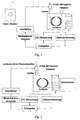
- Fig. 1 and Fig. 2 each show in a schematic schematic representation of an embodiment of the basic structure of an arrangement for carrying out an inventive analysis of mixtures, in particular complex chemical and / or biochemical mixtures.
- This is a coming from a chemical reactor to be analyzed Mixture fed as a continuous stream of a device (injector) for generating pulsed mixtures.
- a device injector
- Exemplary embodiments of corresponding devices for producing pulsed substance mixtures are disclosed in US Pat Fig. 3 to Fig. 7 and are explained in more detail below in connection with these.
- the continuous substance mixture flow of the substance mixture to be analyzed is in the embodiment according to Fig. 1 supplied by a chemical reactor.
- the mixed substance pulses generated by the pulsed substance generating device are then applied to the fused-silica (fs-column) column of a separator gas chromatograph (GC).
- a separator gas chromatograph On the part of the gas chromatograph (GC), the substances of the substance mixture to be analyzed are separated from each other. The separated substances are then detected by an evaluation device.
- the evaluation device is in the in Fig. 1 illustrated embodiment formed by a detector of the gas chromatograph. At the in Fig. 2 In the embodiment shown, the evaluation device is a spectrometer coupled to the gas chromatograph (GC).
- a control device of the gas chromatograph (GC)
- a data acquisition device and one used by the device (injector) for generating mixed substance pulses as a modulator, connected to an amplifier means (modulation sequence) to produce a unique binary sequence of the substance mixture pulses
- a computing device connected to the components (computer).
- a precise control of the injection of the substance mixture (analytes) into the chromatographic separation system is required.
- this control comprises a precise and defined time control of the time interval between successive injections of the pulsed substance mixture into the separation device (gas chromatographs) and the duration of injection within such a time interval.
- a precise and defined control of the quantity of the substance mixture (sample quantity) is required.
- valve circuits used hitherto in the state of the art for generating pulsed substance mixtures are slow and the control of the sample volume is inflexible, in particular by sample grinding. Furthermore, pressure pulses occur due to a valve circuit coupled directly to the chromatographic system, which leads to so-called system peaks in the chromatogram, since no continuous flow occurs in the chromatographic system.
- Fig. 1 and Fig. 2 used device (injector cf-SSL-MP injector) for generating pulsed mixtures, preferably for gas chromatography (GC) (see. Fig. 1 and Fig. 2 ) can be connected to a split / splitless injector of the gas chromatograph by simple mounting.
- GC gas chromatography
- SFC supercritical liquid chromatography
- Fig. 3 and Fig. 4a to 4c such as Fig. 5 and Fig. 6a to 6c each show an embodiment of a device according to the invention (injector, cf-SSL-MP injector) for generating pulsed mixtures.
- injector cf-SSL-MP injector
- a substance mixture to be analyzed can be injected into a separating device.
- the embodiment according to Fig. 5 and Fig. 6a to 6c allows a switched injecting of up to seven mixtures.
- the devices each consist of a heatable metal block (sample block), with holes for the respective injection channels - in the embodiment according to Fig. 3 and Fig. 4a to 4c an injection channel and in the embodiment according to Fig. 5 and Fig. 6a to 6c seven injection channels (sample channels) -. is provided.
- the injection channels take capillary lines of the respective substance mixture to be analyzed, ie the respective sample source, preferably from a parallelized reactor, multi-well plates or similar source.
- the sample block has heating devices and thermocouples for exact temperature control.
- Each injection channel (sample channel) has a gas supply line that can be controlled with a fast pressure valve with switching times in the millisecond range.
- this gas supply line can also be used as flushing line of the respective sample channel.
- the flushing can also be controlled with the controllable or switchable pressure valve.
- the respective gas supply lines can be controlled individually and or synchronously.
- the injection of the analyte mixture into a needle that takes place in the existing split / splittless injector of the separator, at Fig. 1 and Fig. 2 of the gas chromatograph is introduced and is there and is heated by the injector.
- the respective configuration of the devices for generating pulsed mixtures according to Fig. 3 and Fig. 4a to 4c respectively Fig. 5 and Fig. 6a to 6c , So with an injection channel (sample channel) in the embodiment according to Fig. 3 and Fig. 4a to 4c or with seven injection channels (sample channels) in the embodiment according to Fig. 5 and Fig. 6a to 6c , Moreover, allows the possibility of flushing the injection needle by a carrier gas flow, in this case in the range of ml / min, the separator (gas chromatograph). This achieves a permanent flushing and avoids contamination of the different substance mixtures (analyte mixtures) to be analyzed by means of multiplexing.
- such additional grit flow is adjustable at the respective injection valves (backwashing) and / or at a split output integrated in the heating block.
- the total chippings flow results from the sum of the respective flows at the valves.
- the volume between the injection needle and the evaporation space of the respective capillaries is advantageously minimized in such an arrangement, in particular in order to avoid dead volumes.
- the pressure surge outside the Injector of the separator takes place and is intercepted by the pressure control of the separator (gas chromatograph) or the split system, occur advantageously no pressure fluctuations in the separation by the device (cf-SSL-MP injector).
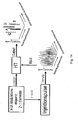
- Fig. 7 shows a further embodiment of an apparatus for generating pulsed mixtures.
- the continuous stream of a substance mixture to be analyzed directly on the separation column of a separation device present, as in Fig. 1 and Fig. 2 represented by the gas chromatograph, modulated by a double-focusing cryogenic modulator.
- the in Fig. 7 illustrated in the basic structure allows in particular an inventive usable for two-dimensional separation techniques coding of the substance mixture to be analyzed.
- the column temperature modulator has two separate modulation chambers.
- the first chamber reaches the focusing of the substance mixture (analyte) to be analyzed
- the modulation of the substance mixture (analyte) to be analyzed takes place according to a binary pseudorandom sequence, which differs from the one in Fig. 1 and Fig. 2 computer unit shown and / or a separate device for generating a corresponding modulation sequence is generated.
- a binary pseudorandom sequence which differs from the one in Fig. 1 and Fig. 2 computer unit shown and / or a separate device for generating a corresponding modulation sequence is generated.
- FIGS. 8 and 10 each show a plot of measured injection stability of a unique binary sequence of a pulsed mixture over time.
- Fig. 9 shows an enlarged section of the diagram Fig. 8 , Based on Fig. 9 is clearly the stability of the peak areas of three different mixtures (analytes) recognizable.
- Fig. 9 shows an enlarged section of the diagram Fig. 8 , Based on Fig
- the pulse duration can be selected short compared to the injection interval, a multiple injection within an injection interval is advantageously possible (oversampling), as a result of which the throughput of substance mixtures to be analyzed (sample throughput) can be increased further.
- the device for generating pulsed mixtures of substances shown in particular in connection with the in Fig. 1 illustrated arrangement for the analysis of mixtures a high-throughput analysis feasible.
- mixtures of substances (analyte samples) to be analyzed are coded with a unique binary sequence.
- the respective injection sections for the respective analyte samples may be of different lengths in order to ensure an equivalent information content.
- Fig. 11 shows in a schematic representation corresponding injection sections for samples A1 to A13 within a binary pseudorandom sequence.
- the injection sequence consists of the same number of elements 0 and 1 or the number can differ by 1 (2 n -1).
- Injection sections of the samples A1 to A13 illustrated by way of example can also be subdivided into calibration and measurement areas in order to enable continuous quantification with internal standardization.
- An element 1 in the binary pseudorandom sequence represents an injection in the form of an injection shock. For an element 0, no injection takes place.
- the respective elements can additionally be subdivided into submodulation sequences, which are constructed identically for all elements, advantageously in order to enable or guarantee multiple injections (oversampling).
- a substance mixture to be analyzed is coded with a unique binary sequence.
- the coding of the analyte sample is carried out by injection device according to Fig. 3 and Fig. 4a to 4c ) or low temperature modulation (device according to Fig.
- the injection sequence consists of the same number of elements 0 and 1 or the number can differ by 1 (2 n -1).
- element 1 a sample is injected or released through the hot air jet.
- element 0 there is no injection or freezing by the cold air jet.
- the injection intervals are calculated according to the required time for a so-called full scan or one Multiples of the duration of a so-called full scan of the spectrometer selected.
- the scan (acquisition) of the spectrometer and the injection interval are synchronized with each other.
- the injection pulse duration or modulation duration in the case of the low-temperature modulator can be chosen to be equal to or shorter than the injection interval or the modulation interval.
- each injection interval or modulation interval advantageously also several different spectroscopic or spectrometric experiments can be performed.
- a bulk full scan and MS / MS or MS n experiments are performed for unambiguous identification and quantification.
- Fig. 12 shows in a diagram the temporal gradual change in concentration of a substance mixture to be analyzed (analyte) as a total chromatogram recorded by the evaluation device.
- the corresponding data of the overall chromatogram are provided by the evaluation device and / or by a data acquisition device (cf. Fig. 1 and Fig. 2 ) in front.
- the raw data are used for further evaluation by means of a computing device (computer) of the evaluation device in particular in the context of a deconvolution for further evaluation.
- an overall chromatogram (cf. Fig. 12 and Fig. 13 ), which is a superposition of n single chromatograms.
- the direct multiplication of the raw data in the circular representation (after 2 n -1 time intervals, the signal intensity is added back to the vector elements at the beginning) with the inverse Hadamard, simplex or inverse matrix of the known binary pseudorandom sequence gives the total chromatogram (cf. Fig. 13 ) of the respective analytes.
- the number k max of the different analytes in the respective samples i and the respective peak shapes results from the overall chromatogram.
- a very good resolution of the peaks is achieved with the embodiments of the analysis method according to the invention, so that the method can also be applied to problems with small separation factors, such as occur, for example, in enantiomer separations for determining the enantiomeric excess ee.
- this overall chromatogram (cf. Fig. 12 ) is characterized by deviations in the baseline, which in turn represents a convolution of the respective analyte concentrations. Therefore, first, a peak shape analysis is performed to obtain the distribution function ⁇ (A k ) of the respective analytes as a function of time. The maximum of each individual analyte peak is normalized to 1.
- the concentration distribution matrix is then filled in such a way that in each column, the relative concentration ⁇ (A i, j, k ) of the analyte A k of the ith sample and j-th repetitive injection depending on the injection sequence and the time interval
- Each line represents the sum of the relative concentrations of the respective analytes in the samples.
- This procedure can be applied to the crude chromatogram in the circular and non-circular representation.
- the respective concentration of the analytes results as a concentration vector which, multiplied by the concentration distribution matrix, yields the signal intensities in each time interval of the crude chromatogram.
- the solution is the concentration of the respective analytes in the samples i.
- the crude chromatogram is converted by means of iterative adaptation with the concentration vector (by forming the difference or by division) and subsequent Hadamard transformation into an overall chromatogram whose deviations in the baseline through further fine-tuning steps be minimized in the solution of the linear equation system.
- Fig. 13 shows on the right side the concentration of the analytes of the respective samples in a circular representation.
Landscapes
- Physics & Mathematics (AREA)
- Health & Medical Sciences (AREA)
- Life Sciences & Earth Sciences (AREA)
- Chemical & Material Sciences (AREA)
- Analytical Chemistry (AREA)
- Biochemistry (AREA)
- General Health & Medical Sciences (AREA)
- General Physics & Mathematics (AREA)
- Immunology (AREA)
- Pathology (AREA)
- Other Investigation Or Analysis Of Materials By Electrical Means (AREA)
- Sampling And Sample Adjustment (AREA)
- Investigating Or Analysing Biological Materials (AREA)
Applications Claiming Priority (2)
| Application Number | Priority Date | Filing Date | Title |
|---|---|---|---|
| DE102005050114A DE102005050114A1 (de) | 2005-10-18 | 2005-10-18 | Analyse von Stoffgemischen |
| EP06805440.2A EP1994403B1 (fr) | 2005-10-18 | 2006-10-17 | Analyse de melanges de substances |
Related Parent Applications (2)
| Application Number | Title | Priority Date | Filing Date |
|---|---|---|---|
| EP06805440.2A Division-Into EP1994403B1 (fr) | 2005-10-18 | 2006-10-17 | Analyse de melanges de substances |
| EP06805440.2A Division EP1994403B1 (fr) | 2005-10-18 | 2006-10-17 | Analyse de melanges de substances |
Publications (2)
| Publication Number | Publication Date |
|---|---|
| EP2042863A1 true EP2042863A1 (fr) | 2009-04-01 |
| EP2042863B1 EP2042863B1 (fr) | 2017-02-22 |
Family
ID=37708348
Family Applications (3)
| Application Number | Title | Priority Date | Filing Date |
|---|---|---|---|
| EP08008888.3A Not-in-force EP2037262B1 (fr) | 2005-10-18 | 2006-10-17 | Production des mélanges pulsées de substances |
| EP06805440.2A Not-in-force EP1994403B1 (fr) | 2005-10-18 | 2006-10-17 | Analyse de melanges de substances |
| EP08008889.1A Not-in-force EP2042863B1 (fr) | 2005-10-18 | 2006-10-17 | Analyse de mélanges de matière |
Family Applications Before (2)
| Application Number | Title | Priority Date | Filing Date |
|---|---|---|---|
| EP08008888.3A Not-in-force EP2037262B1 (fr) | 2005-10-18 | 2006-10-17 | Production des mélanges pulsées de substances |
| EP06805440.2A Not-in-force EP1994403B1 (fr) | 2005-10-18 | 2006-10-17 | Analyse de melanges de substances |
Country Status (5)
| Country | Link |
|---|---|
| US (1) | US8297135B2 (fr) |
| EP (3) | EP2037262B1 (fr) |
| JP (1) | JP5289961B2 (fr) |
| DE (1) | DE102005050114A1 (fr) |
| WO (1) | WO2007045224A2 (fr) |
Families Citing this family (11)
| Publication number | Priority date | Publication date | Assignee | Title |
|---|---|---|---|---|
| US9138657B1 (en) * | 2011-07-28 | 2015-09-22 | Elemental Scientific, Inc. | Fractional-volatilization separator |
| US9909957B1 (en) | 2011-12-30 | 2018-03-06 | Elemental Scientific, Inc. | Introducing hydrogen gas to an ICP instrument for enhanced detection of low-sensitivity elements |
| DE102013006542B4 (de) * | 2013-04-16 | 2017-03-23 | Dräger Safety AG & Co. KGaA | Messvorrichtung, Reaktionsträger und Messverfahren |
| EP2818859A1 (fr) * | 2013-06-28 | 2014-12-31 | Ruprecht-Karls-Universität Heidelberg | Dispositif chromatographique et son procédé |
| US9322812B2 (en) | 2014-01-17 | 2016-04-26 | Institut Francais Des Sciences Et Technologies Des Transports, De L'amenagement Et Des Reseaux (Ifsttar) | Multiple sample chromatography using a stochastic injection technique |
| WO2015131293A1 (fr) * | 2014-03-04 | 2015-09-11 | Tofwerk Ag | Procédé et appareil de détermination d'un chromatogramme |
| FR3104586B1 (fr) | 2019-12-17 | 2021-12-03 | Michelin & Cie | Composé diorganomagnésien asymétrique pour système catalytique |
| FR3104584B1 (fr) | 2019-12-17 | 2021-12-03 | Michelin & Cie | Composé diorganomagnésien asymétrique |
| FR3116276B1 (fr) | 2020-11-19 | 2023-11-10 | Michelin & Cie | Diorganomagnésien ayant une chaîne diénique ou oléfinique et fonctionnelle amine |
| FR3116277A1 (fr) | 2020-11-19 | 2022-05-20 | Compagnie Generale Des Etablissements Michelin | Copolymères fonctionnels amine à blocs éthyléniques et diéniques |
| FR3116538B1 (fr) | 2020-11-24 | 2022-11-25 | Michelin & Cie | Co-catalyseur comprenant plusieurs liaisons carbone magnésium |
Citations (7)
| Publication number | Priority date | Publication date | Assignee | Title |
|---|---|---|---|---|
| DE3001425A1 (de) * | 1979-01-17 | 1980-10-16 | Erba Strumentazione | Verdampfungsinjektor fuer gaschromatographen-saeulen |
| GB2268096A (en) * | 1992-04-15 | 1994-01-05 | Janusz Boleslaw Pawliszyn | Process and device for continuous extraction and analysis of fluid using membrane |
| EP0685738A1 (fr) * | 1994-05-31 | 1995-12-06 | Hewlett-Packard Company | Contrôle pneumatique reconfigurable pour injection divisée ou non-divisée |
| US5954862A (en) * | 1998-01-29 | 1999-09-21 | Hewlett-Packard Company | Sample inlet liner |
| DE19817017A1 (de) * | 1998-04-17 | 1999-10-28 | Gerstel Gmbh & Co Kg | Heizpatrone für eine gaschromatographische Überführungseinrichtung |
| DE10133774A1 (de) * | 2001-07-16 | 2003-02-06 | Joint Analytical Systems Gmbh | Verdampferrohr zum Verdampfen von flüssigen Proben für die Kapillar-Gaschromatographie |
| US20070144918A1 (en) | 2005-12-23 | 2007-06-28 | Apex Biotechnology Corp. | Electrochemical test strip |
Family Cites Families (15)
| Publication number | Priority date | Publication date | Assignee | Title |
|---|---|---|---|---|
| US3535084A (en) * | 1965-05-29 | 1970-10-20 | Katsuhisa Furuta | Automatic and continuous analysis of multiple components |
| CS182967B1 (en) * | 1974-04-04 | 1978-05-31 | Jan Jokl | Dividing analysis equipment |
| JPS6192870U (fr) * | 1984-11-22 | 1986-06-16 | ||
| JPS63315923A (ja) * | 1987-06-18 | 1988-12-23 | Shimadzu Corp | マルチチャネル検出器の信号処理装置 |
| US6017693A (en) * | 1994-03-14 | 2000-01-25 | University Of Washington | Identification of nucleotides, amino acids, or carbohydrates by mass spectrometry |
| JP3270290B2 (ja) * | 1994-04-28 | 2002-04-02 | 株式会社日立製作所 | マルチチャンネルクロマトグラムの解析方法及びデータ処理装置 |
| US5744654A (en) * | 1996-06-14 | 1998-04-28 | Merichem Company | Recovery of para-ethylphenol |
| WO2000047701A2 (fr) * | 1999-02-10 | 2000-08-17 | Eastman Chemical Company | Production de produits chimiques et de materiaux de pointe a partir de fibre de maïs |
| DE19949551C2 (de) * | 1999-10-14 | 2001-12-13 | Agilent Technologies Inc | Mikrofluidischer Mikrochip, Energieversorgungseinrichtung und Verfahren zum Betrieb eines mikrofluidischen Mikrochips |
| EP1251939B1 (fr) * | 2000-01-12 | 2011-06-29 | Zoex Licensing Corporation | Modulation thermique transversale |
| US6497138B1 (en) * | 2000-10-18 | 2002-12-24 | Agilent Technologies, Inc., | Multilayered gas chromatograph |
| DE60117040T2 (de) * | 2000-12-19 | 2006-09-21 | Thermo Electron S.P.A. | Modulator für die gaschromatographie |
| EP1472535A1 (fr) * | 2002-02-04 | 2004-11-03 | Thermo Finnigan Italia S.p.A. | Procede et dispositif perfectionne de chromatographie en phase gazeuse bidimensionnelle |
| US7067803B2 (en) | 2002-10-11 | 2006-06-27 | The Board Of Trustees Of The Leland Stanford Junior University | Gating device and driver for modulation of charged particle beams |
| JP4306481B2 (ja) * | 2004-02-06 | 2009-08-05 | 株式会社島津製作所 | クロマトグラフ分析装置 |
-
2005
- 2005-10-18 DE DE102005050114A patent/DE102005050114A1/de not_active Ceased
-
2006
- 2006-10-17 EP EP08008888.3A patent/EP2037262B1/fr not_active Not-in-force
- 2006-10-17 EP EP06805440.2A patent/EP1994403B1/fr not_active Not-in-force
- 2006-10-17 JP JP2008535880A patent/JP5289961B2/ja not_active Expired - Fee Related
- 2006-10-17 WO PCT/DE2006/001834 patent/WO2007045224A2/fr active Application Filing
- 2006-10-17 US US12/090,687 patent/US8297135B2/en not_active Expired - Fee Related
- 2006-10-17 EP EP08008889.1A patent/EP2042863B1/fr not_active Not-in-force
Patent Citations (7)
| Publication number | Priority date | Publication date | Assignee | Title |
|---|---|---|---|---|
| DE3001425A1 (de) * | 1979-01-17 | 1980-10-16 | Erba Strumentazione | Verdampfungsinjektor fuer gaschromatographen-saeulen |
| GB2268096A (en) * | 1992-04-15 | 1994-01-05 | Janusz Boleslaw Pawliszyn | Process and device for continuous extraction and analysis of fluid using membrane |
| EP0685738A1 (fr) * | 1994-05-31 | 1995-12-06 | Hewlett-Packard Company | Contrôle pneumatique reconfigurable pour injection divisée ou non-divisée |
| US5954862A (en) * | 1998-01-29 | 1999-09-21 | Hewlett-Packard Company | Sample inlet liner |
| DE19817017A1 (de) * | 1998-04-17 | 1999-10-28 | Gerstel Gmbh & Co Kg | Heizpatrone für eine gaschromatographische Überführungseinrichtung |
| DE10133774A1 (de) * | 2001-07-16 | 2003-02-06 | Joint Analytical Systems Gmbh | Verdampferrohr zum Verdampfen von flüssigen Proben für die Kapillar-Gaschromatographie |
| US20070144918A1 (en) | 2005-12-23 | 2007-06-28 | Apex Biotechnology Corp. | Electrochemical test strip |
Also Published As
| Publication number | Publication date |
|---|---|
| JP5289961B2 (ja) | 2013-09-11 |
| US20080295617A1 (en) | 2008-12-04 |
| EP1994403A2 (fr) | 2008-11-26 |
| US8297135B2 (en) | 2012-10-30 |
| WO2007045224A2 (fr) | 2007-04-26 |
| EP1994403B1 (fr) | 2017-05-31 |
| EP2042863B1 (fr) | 2017-02-22 |
| WO2007045224A3 (fr) | 2007-08-02 |
| DE102005050114A1 (de) | 2007-04-19 |
| JP2009511924A (ja) | 2009-03-19 |
| EP2037262B1 (fr) | 2017-02-22 |
| EP2037262A1 (fr) | 2009-03-18 |
Similar Documents
| Publication | Publication Date | Title |
|---|---|---|
| EP1994403B1 (fr) | Analyse de melanges de substances | |
| DE102012214217B4 (de) | In-Situ-Konditionieren bei Massenspektrometersystemen | |
| DE69711308T2 (de) | Bestimmung der Siedepunktkurven eines Rohöls oder einer Fraktion | |
| EP1481416B1 (fr) | Procede de spectrometrie de masse pour analyser des melanges de substances | |
| DE10392707B4 (de) | Verfahren zur Verwendung von Datenbinning bei der Analyse von Chromatographie-/Spektrometriedaten | |
| EP2110663B1 (fr) | Analyseur GC-MS commutable entre des types de fonctionnement unidimensionnel et bidimensionnel | |
| DE69205910T2 (de) | Thermisches Modulationseinlasssystem für Gaschromatographie. | |
| CH616275A5 (fr) | ||
| DE102017011423B4 (de) | Verfahren und Vorrichtung für lsotopenverhältnis-Massenspektrometrie | |
| DE102016200165A1 (de) | Massenkorrektur | |
| EP2446460A1 (fr) | Contrôle fonctionnel ou compensation de la variance en spectrométrie de masse | |
| DE102010002316A1 (de) | Analysesystem mit Kopplung von GPC und NMR-Spektroskopie, insbesondere für die Analyse von polymerhaltigen Messproben | |
| DE2755091A1 (de) | Messverfahren fuer magnetische kernresonanz | |
| DE112015004216T5 (de) | Techniken für die Darstellung und Verarbeitung von Massenspektraldaten | |
| DE102009048063A1 (de) | Ionisationsverfahren, Ionenerzeugungsvorrichtung sowie Verwendung derselben bei der Ionenmobilitätsspektronomie | |
| DE19709172A1 (de) | Verfahren der vergleichenden Analyse mit Ionenfallenmassenspektrometern | |
| DE19713194C2 (de) | Verfahren und Anordnung zum Erkennen von Eigenschaften einer Probe auf der Basis der Massenspektroskopie | |
| EP0770870B1 (fr) | Vanne et son utilisation | |
| DE102022101886A1 (de) | Verfahren sowie Vorrichtung zum Kalibrieren einer Gasdetektionsvorrichtung | |
| DE102008048085A1 (de) | Unterscheidung von Enantiomeren mit Hilfe der breitbandigen Femtosekunden-Circulardichroismus-Massenspektrometrie | |
| DE102023003851A1 (de) | System und Verfahren zur Analyse und Identifizierung von Gasen und verdampfbaren Stoffen | |
| EP3093658B1 (fr) | Dispositif et procédé d'analyse de gaz | |
| EP1163505A1 (fr) | Dispositif pour analyser des elements contenus dans des echantillons de liquides sous forme de gouttelettes | |
| EP1333382A1 (fr) | Méthode et dispositif de traitement de données de mesure | |
| WO2002094431A2 (fr) | Laboratoire de chimie miniature integre |
Legal Events
| Date | Code | Title | Description |
|---|---|---|---|
| PUAI | Public reference made under article 153(3) epc to a published international application that has entered the european phase |
Free format text: ORIGINAL CODE: 0009012 |
|
| 17P | Request for examination filed |
Effective date: 20080528 |
|
| AC | Divisional application: reference to earlier application |
Ref document number: 1994403 Country of ref document: EP Kind code of ref document: P |
|
| AK | Designated contracting states |
Kind code of ref document: A1 Designated state(s): AT BE BG CH CY CZ DE DK EE ES FI FR GB GR HU IE IS IT LI LT LU LV MC NL PL PT RO SE SI SK TR |
|
| AX | Request for extension of the european patent |
Extension state: AL BA HR MK RS |
|
| 17Q | First examination report despatched |
Effective date: 20090604 |
|
| AKX | Designation fees paid |
Designated state(s): AT BE BG CH CY CZ DE DK EE ES FI FR GB GR HU IE IS IT LI LT LU LV MC NL PL PT RO SE SI SK TR |
|
| GRAP | Despatch of communication of intention to grant a patent |
Free format text: ORIGINAL CODE: EPIDOSNIGR1 |
|
| INTG | Intention to grant announced |
Effective date: 20160506 |
|
| GRAJ | Information related to disapproval of communication of intention to grant by the applicant or resumption of examination proceedings by the epo deleted |
Free format text: ORIGINAL CODE: EPIDOSDIGR1 |
|
| GRAP | Despatch of communication of intention to grant a patent |
Free format text: ORIGINAL CODE: EPIDOSNIGR1 |
|
| INTC | Intention to grant announced (deleted) | ||
| INTG | Intention to grant announced |
Effective date: 20160831 |
|
| GRAS | Grant fee paid |
Free format text: ORIGINAL CODE: EPIDOSNIGR3 |
|
| GRAA | (expected) grant |
Free format text: ORIGINAL CODE: 0009210 |
|
| AC | Divisional application: reference to earlier application |
Ref document number: 1994403 Country of ref document: EP Kind code of ref document: P |
|
| AK | Designated contracting states |
Kind code of ref document: B1 Designated state(s): AT BE BG CH CY CZ DE DK EE ES FI FR GB GR HU IE IS IT LI LT LU LV MC NL PL PT RO SE SI SK TR |
|
| REG | Reference to a national code |
Ref country code: GB Ref legal event code: FG4D Free format text: NOT ENGLISH |
|
| REG | Reference to a national code |
Ref country code: CH Ref legal event code: EP |
|
| REG | Reference to a national code |
Ref country code: AT Ref legal event code: REF Ref document number: 869654 Country of ref document: AT Kind code of ref document: T Effective date: 20170315 |
|
| REG | Reference to a national code |
Ref country code: IE Ref legal event code: FG4D Free format text: LANGUAGE OF EP DOCUMENT: GERMAN |
|
| REG | Reference to a national code |
Ref country code: DE Ref legal event code: R096 Ref document number: 502006015369 Country of ref document: DE |
|
| REG | Reference to a national code |
Ref country code: LT Ref legal event code: MG4D |
|
| REG | Reference to a national code |
Ref country code: NL Ref legal event code: MP Effective date: 20170222 |
|
| PG25 | Lapsed in a contracting state [announced via postgrant information from national office to epo] |
Ref country code: GR Free format text: LAPSE BECAUSE OF FAILURE TO SUBMIT A TRANSLATION OF THE DESCRIPTION OR TO PAY THE FEE WITHIN THE PRESCRIBED TIME-LIMIT Effective date: 20170523 Ref country code: LT Free format text: LAPSE BECAUSE OF FAILURE TO SUBMIT A TRANSLATION OF THE DESCRIPTION OR TO PAY THE FEE WITHIN THE PRESCRIBED TIME-LIMIT Effective date: 20170222 Ref country code: FI Free format text: LAPSE BECAUSE OF FAILURE TO SUBMIT A TRANSLATION OF THE DESCRIPTION OR TO PAY THE FEE WITHIN THE PRESCRIBED TIME-LIMIT Effective date: 20170222 |
|
| PG25 | Lapsed in a contracting state [announced via postgrant information from national office to epo] |
Ref country code: LV Free format text: LAPSE BECAUSE OF FAILURE TO SUBMIT A TRANSLATION OF THE DESCRIPTION OR TO PAY THE FEE WITHIN THE PRESCRIBED TIME-LIMIT Effective date: 20170222 Ref country code: SE Free format text: LAPSE BECAUSE OF FAILURE TO SUBMIT A TRANSLATION OF THE DESCRIPTION OR TO PAY THE FEE WITHIN THE PRESCRIBED TIME-LIMIT Effective date: 20170222 Ref country code: ES Free format text: LAPSE BECAUSE OF FAILURE TO SUBMIT A TRANSLATION OF THE DESCRIPTION OR TO PAY THE FEE WITHIN THE PRESCRIBED TIME-LIMIT Effective date: 20170222 Ref country code: PT Free format text: LAPSE BECAUSE OF FAILURE TO SUBMIT A TRANSLATION OF THE DESCRIPTION OR TO PAY THE FEE WITHIN THE PRESCRIBED TIME-LIMIT Effective date: 20170622 Ref country code: NL Free format text: LAPSE BECAUSE OF FAILURE TO SUBMIT A TRANSLATION OF THE DESCRIPTION OR TO PAY THE FEE WITHIN THE PRESCRIBED TIME-LIMIT Effective date: 20170222 Ref country code: BG Free format text: LAPSE BECAUSE OF FAILURE TO SUBMIT A TRANSLATION OF THE DESCRIPTION OR TO PAY THE FEE WITHIN THE PRESCRIBED TIME-LIMIT Effective date: 20170522 |
|
| REG | Reference to a national code |
Ref country code: FR Ref legal event code: PLFP Year of fee payment: 12 |
|
| PG25 | Lapsed in a contracting state [announced via postgrant information from national office to epo] |
Ref country code: IT Free format text: LAPSE BECAUSE OF FAILURE TO SUBMIT A TRANSLATION OF THE DESCRIPTION OR TO PAY THE FEE WITHIN THE PRESCRIBED TIME-LIMIT Effective date: 20170222 Ref country code: EE Free format text: LAPSE BECAUSE OF FAILURE TO SUBMIT A TRANSLATION OF THE DESCRIPTION OR TO PAY THE FEE WITHIN THE PRESCRIBED TIME-LIMIT Effective date: 20170222 Ref country code: SK Free format text: LAPSE BECAUSE OF FAILURE TO SUBMIT A TRANSLATION OF THE DESCRIPTION OR TO PAY THE FEE WITHIN THE PRESCRIBED TIME-LIMIT Effective date: 20170222 Ref country code: CZ Free format text: LAPSE BECAUSE OF FAILURE TO SUBMIT A TRANSLATION OF THE DESCRIPTION OR TO PAY THE FEE WITHIN THE PRESCRIBED TIME-LIMIT Effective date: 20170222 Ref country code: RO Free format text: LAPSE BECAUSE OF FAILURE TO SUBMIT A TRANSLATION OF THE DESCRIPTION OR TO PAY THE FEE WITHIN THE PRESCRIBED TIME-LIMIT Effective date: 20170222 |
|
| REG | Reference to a national code |
Ref country code: DE Ref legal event code: R097 Ref document number: 502006015369 Country of ref document: DE |
|
| PG25 | Lapsed in a contracting state [announced via postgrant information from national office to epo] |
Ref country code: DK Free format text: LAPSE BECAUSE OF FAILURE TO SUBMIT A TRANSLATION OF THE DESCRIPTION OR TO PAY THE FEE WITHIN THE PRESCRIBED TIME-LIMIT Effective date: 20170222 Ref country code: PL Free format text: LAPSE BECAUSE OF FAILURE TO SUBMIT A TRANSLATION OF THE DESCRIPTION OR TO PAY THE FEE WITHIN THE PRESCRIBED TIME-LIMIT Effective date: 20170222 |
|
| PGFP | Annual fee paid to national office [announced via postgrant information from national office to epo] |
Ref country code: LU Payment date: 20171019 Year of fee payment: 12 |
|
| PLBE | No opposition filed within time limit |
Free format text: ORIGINAL CODE: 0009261 |
|
| STAA | Information on the status of an ep patent application or granted ep patent |
Free format text: STATUS: NO OPPOSITION FILED WITHIN TIME LIMIT |
|
| 26N | No opposition filed |
Effective date: 20171123 |
|
| PGFP | Annual fee paid to national office [announced via postgrant information from national office to epo] |
Ref country code: DE Payment date: 20171019 Year of fee payment: 12 Ref country code: FR Payment date: 20171024 Year of fee payment: 12 |
|
| PG25 | Lapsed in a contracting state [announced via postgrant information from national office to epo] |
Ref country code: SI Free format text: LAPSE BECAUSE OF FAILURE TO SUBMIT A TRANSLATION OF THE DESCRIPTION OR TO PAY THE FEE WITHIN THE PRESCRIBED TIME-LIMIT Effective date: 20170222 |
|
| PGFP | Annual fee paid to national office [announced via postgrant information from national office to epo] |
Ref country code: IE Payment date: 20171025 Year of fee payment: 12 Ref country code: BE Payment date: 20171019 Year of fee payment: 12 Ref country code: CH Payment date: 20171019 Year of fee payment: 12 Ref country code: GB Payment date: 20171019 Year of fee payment: 12 |
|
| PG25 | Lapsed in a contracting state [announced via postgrant information from national office to epo] |
Ref country code: MC Free format text: LAPSE BECAUSE OF FAILURE TO SUBMIT A TRANSLATION OF THE DESCRIPTION OR TO PAY THE FEE WITHIN THE PRESCRIBED TIME-LIMIT Effective date: 20170222 |
|
| REG | Reference to a national code |
Ref country code: AT Ref legal event code: MM01 Ref document number: 869654 Country of ref document: AT Kind code of ref document: T Effective date: 20171017 |
|
| PG25 | Lapsed in a contracting state [announced via postgrant information from national office to epo] |
Ref country code: AT Free format text: LAPSE BECAUSE OF NON-PAYMENT OF DUE FEES Effective date: 20171017 |
|
| REG | Reference to a national code |
Ref country code: DE Ref legal event code: R119 Ref document number: 502006015369 Country of ref document: DE |
|
| REG | Reference to a national code |
Ref country code: CH Ref legal event code: PL |
|
| GBPC | Gb: european patent ceased through non-payment of renewal fee |
Effective date: 20181017 |
|
| REG | Reference to a national code |
Ref country code: BE Ref legal event code: MM Effective date: 20181031 |
|
| PG25 | Lapsed in a contracting state [announced via postgrant information from national office to epo] |
Ref country code: LU Free format text: LAPSE BECAUSE OF NON-PAYMENT OF DUE FEES Effective date: 20181017 Ref country code: HU Free format text: LAPSE BECAUSE OF FAILURE TO SUBMIT A TRANSLATION OF THE DESCRIPTION OR TO PAY THE FEE WITHIN THE PRESCRIBED TIME-LIMIT; INVALID AB INITIO Effective date: 20061017 |
|
| REG | Reference to a national code |
Ref country code: IE Ref legal event code: MM4A |
|
| PG25 | Lapsed in a contracting state [announced via postgrant information from national office to epo] |
Ref country code: DE Free format text: LAPSE BECAUSE OF NON-PAYMENT OF DUE FEES Effective date: 20190501 |
|
| PG25 | Lapsed in a contracting state [announced via postgrant information from national office to epo] |
Ref country code: BE Free format text: LAPSE BECAUSE OF NON-PAYMENT OF DUE FEES Effective date: 20181031 Ref country code: CH Free format text: LAPSE BECAUSE OF NON-PAYMENT OF DUE FEES Effective date: 20181031 Ref country code: FR Free format text: LAPSE BECAUSE OF NON-PAYMENT OF DUE FEES Effective date: 20181031 Ref country code: LI Free format text: LAPSE BECAUSE OF NON-PAYMENT OF DUE FEES Effective date: 20181031 |
|
| PG25 | Lapsed in a contracting state [announced via postgrant information from national office to epo] |
Ref country code: GB Free format text: LAPSE BECAUSE OF NON-PAYMENT OF DUE FEES Effective date: 20181017 Ref country code: IE Free format text: LAPSE BECAUSE OF NON-PAYMENT OF DUE FEES Effective date: 20181017 Ref country code: CY Free format text: LAPSE BECAUSE OF NON-PAYMENT OF DUE FEES Effective date: 20170222 |
|
| PG25 | Lapsed in a contracting state [announced via postgrant information from national office to epo] |
Ref country code: TR Free format text: LAPSE BECAUSE OF FAILURE TO SUBMIT A TRANSLATION OF THE DESCRIPTION OR TO PAY THE FEE WITHIN THE PRESCRIBED TIME-LIMIT Effective date: 20170222 |
|
| PG25 | Lapsed in a contracting state [announced via postgrant information from national office to epo] |
Ref country code: IS Free format text: LAPSE BECAUSE OF FAILURE TO SUBMIT A TRANSLATION OF THE DESCRIPTION OR TO PAY THE FEE WITHIN THE PRESCRIBED TIME-LIMIT Effective date: 20170622 |