EP2040341A2 - Elektrischer Steckverbinder - Google Patents
Elektrischer Steckverbinder Download PDFInfo
- Publication number
- EP2040341A2 EP2040341A2 EP08014608A EP08014608A EP2040341A2 EP 2040341 A2 EP2040341 A2 EP 2040341A2 EP 08014608 A EP08014608 A EP 08014608A EP 08014608 A EP08014608 A EP 08014608A EP 2040341 A2 EP2040341 A2 EP 2040341A2
- Authority
- EP
- European Patent Office
- Prior art keywords
- housing
- connector
- protective device
- receiving opening
- plug
- Prior art date
- Legal status (The legal status is an assumption and is not a legal conclusion. Google has not performed a legal analysis and makes no representation as to the accuracy of the status listed.)
- Granted
Links
- 230000001681 protective effect Effects 0.000 claims abstract description 37
- 238000011109 contamination Methods 0.000 claims description 7
- 238000007789 sealing Methods 0.000 claims description 6
- 230000008719 thickening Effects 0.000 claims description 6
- 238000000926 separation method Methods 0.000 claims description 3
- 230000001012 protector Effects 0.000 claims 2
- 239000000428 dust Substances 0.000 description 2
- 230000006835 compression Effects 0.000 description 1
- 238000007906 compression Methods 0.000 description 1
- 239000000356 contaminant Substances 0.000 description 1
- 230000001419 dependent effect Effects 0.000 description 1
- 230000008021 deposition Effects 0.000 description 1
- 239000013013 elastic material Substances 0.000 description 1
- 238000009434 installation Methods 0.000 description 1
- 239000002689 soil Substances 0.000 description 1
- 239000000725 suspension Substances 0.000 description 1
Images
Classifications
-
- H—ELECTRICITY
- H01—ELECTRIC ELEMENTS
- H01R—ELECTRICALLY-CONDUCTIVE CONNECTIONS; STRUCTURAL ASSOCIATIONS OF A PLURALITY OF MUTUALLY-INSULATED ELECTRICAL CONNECTING ELEMENTS; COUPLING DEVICES; CURRENT COLLECTORS
- H01R13/00—Details of coupling devices of the kinds covered by groups H01R12/70 or H01R24/00 - H01R33/00
- H01R13/46—Bases; Cases
- H01R13/52—Dustproof, splashproof, drip-proof, waterproof, or flameproof cases
- H01R13/5213—Covers
-
- H—ELECTRICITY
- H01—ELECTRIC ELEMENTS
- H01R—ELECTRICALLY-CONDUCTIVE CONNECTIONS; STRUCTURAL ASSOCIATIONS OF A PLURALITY OF MUTUALLY-INSULATED ELECTRICAL CONNECTING ELEMENTS; COUPLING DEVICES; CURRENT COLLECTORS
- H01R13/00—Details of coupling devices of the kinds covered by groups H01R12/70 or H01R24/00 - H01R33/00
- H01R13/44—Means for preventing access to live contacts
- H01R13/447—Shutter or cover plate
-
- H—ELECTRICITY
- H01—ELECTRIC ELEMENTS
- H01R—ELECTRICALLY-CONDUCTIVE CONNECTIONS; STRUCTURAL ASSOCIATIONS OF A PLURALITY OF MUTUALLY-INSULATED ELECTRICAL CONNECTING ELEMENTS; COUPLING DEVICES; CURRENT COLLECTORS
- H01R24/00—Two-part coupling devices, or either of their cooperating parts, characterised by their overall structure
- H01R24/60—Contacts spaced along planar side wall transverse to longitudinal axis of engagement
- H01R24/62—Sliding engagements with one side only, e.g. modular jack coupling devices
- H01R24/64—Sliding engagements with one side only, e.g. modular jack coupling devices for high frequency, e.g. RJ 45
Definitions
- the invention relates to an electrical connector according to the preamble of claim 1. Furthermore, the invention relates to a protective device for an electrical connector.
- the housing of the electrical plug connectors disclosed therein is formed by two sections, namely a front housing section into which a data plug can be inserted by contacting the connecting device via a plug receiving opening of the housing, and by a rear housing section via which a data cable is positioned in the housing Connecting device is approachable.
- the connecting device comprises contact springs and boards, wherein the same is sensitive to contamination. Then, when no data plug is inserted into the plug receiving opening of the housing, the plug receiving opening is open and the connecting means can be easily removed by deposition of e.g. B. Dirty dust.
- the present invention is based on the problem to provide a novel electrical connector and a novel protection device for an electrical connector.
- the plug connector comprises a protective device designed as a separate module relative to the housing so as to protect the connecting device positioned in the housing against contamination when no data plug is inserted into the plug receiving opening of the housing, the protective device having an elastic connection region over which the protective device is releasably connected to the housing, wherein the protective device is displaceable by pivoting about the elastic connection region between a first position in which it releases the plug receiving opening, and a second position in which it closes the plug receiving opening.
- the trained as a separate module protection device has a simple structure and can, if no data plug is inserted into the connector receiving opening of the housing, effectively protect the positioned in the housing connection device from contamination.
- the elastic connection region of the protective device engages in at least one recess of the housing formed adjacent to the plug receiving opening, wherein the protective device is captively fastened to the housing via the elastic connection region.
- the protection device for an electrical connector is defined in claim 12.
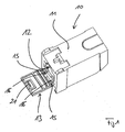
- Fig. 1 shows a perspective view of an inventive, designed as a data socket electrical connector 10th
- the connector 10 has a housing 11 in which an unillustrated connection device is positioned. On one side of the housing 11, a plug receptacle opening 12 is formed, via which a data plug is at least partially inserted into the housing 11 in order to contact the same with the positioned in the housing 11 connecting device.
- the plug connector opening 12 may, for. B. act to an RJ45 data connector, in which case the connector receiving opening 12 has a matched to the RJ45 data connector contour.
- the invention is not limited to RJ45 data sockets for receiving RJ45 data plugs, but the invention can also be used with other electrical data sockets.
- the plug receiving opening 12 is open, in which case via the plug receiving opening 12 soils such. B. dust can penetrate into the housing 11 and can get into the region of the connecting device. Since the connector includes contact springs and boards, it is sensitive to such contaminants, so there is a need to protect the connector of a data jack from contamination.
- the electrical connector 10 comprises a protection device 13, with which, when no data connector is inserted into the connector receiving opening 12 of the housing 11, the connector receiving opening 12 can be closed, so as to protect the connection device positioned in the housing 11 from contamination.
- the protective device 13 is formed with respect to the housing 11 as a separate assembly and has an elastic connection region 14, which is formed in the illustrated embodiment of elastic, rod-like projections 15.
- the protective device 13 is connected to the housing 11 of the data socket 10 via the elastic connection region 14, the protective device 13 being pivoted about the elastic connection region 14 between a first position, in which it releases the plug receiving opening 12, and a second position, in which the same the plug receiving opening 12 closes, is displaced.
- the recesses 16 are contoured such that the rod-like projections 15 after an elastic compression or Auftechnologyzubessel same can be threaded through the ends thereof formed thickenings 17 in first, inner sections, the recesses 16, wherein after threading the rod-like projections 15 due to their Elasticity move apart and get into outer portions of the recesses 16, which have a smaller cross-section than the inner portions of the recesses 16 and as the thickenings 17.
- the protective device 13 is captively fastened to the housing 11 of the connector 10.
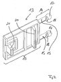
- Fig. 2 can be taken, two rod-like projections 15 which form the elastic connection portion 14 of the protection device 13, adjacent to the thickenings 17 assigned to predetermined separation points 18, via which a protective device 13 which is unvelierbar attached to the housing 11 of the connector 10, in particular under suspension the captive can be separated from the housing 11 when the recesses 16 of the housing 11 due to the installation situation of the connector 10 are no longer accessible.
- the connection region 14 can then be severed in the region of the predetermined separation points 18, wherein the protective device 13 can be used to close the connector receiving opening 12 even in the separated state. The cutting of the breakpoints is done without tools.
- the protective device 13 Opposite or adjacent to the elastic connection region 14, the protective device 13 has a closure region 19 which, when the protective device 13 assumes the second position, closes the connector receiving opening 12 of the connector 10.
- the sealing area 19 is assigned two sealing lips 20, 21 which, when the protective device 13 assumes the second position, seal the plug receiving opening 12 to the outside.
- the sealing lips 20, 21 are adapted to the contour of the connector receiving opening 12 of the housing 11 of the connector 10.
- the entire protective device 13 is integrally formed and made of an elastic material, for. B. made of TPU. This allows a particularly cost-effective design of the protective device 13th
Landscapes
- Connector Housings Or Holding Contact Members (AREA)
- Details Of Connecting Devices For Male And Female Coupling (AREA)
Abstract
Description
- Die Erfindung betrifft einen elektrischen Steckverbinder nach dem Oberbegriff des Anspruchs 1. Des weiteren betrifft die Erfindung eine Schutzvorrichtung für einen elektrischen Steckverbinder.
- Aus der
US 2006/0014410 A1 undWO 2001/052364 sind als Datenbuchsen ausgebildete elektrische Steckverbinder bekannt, die ein Gehäuse und eine im Gehäuse positionierte Verbindungseinrichtung aufweisen. Das Gehäuse der dort offenbarten elektrischen Steckverbinder wird von zwei Abschnitten gebildet, nämlich von einem vorderen Gehäuseäbschnitt, in welchen über eine Steckeraufnahmeöffnung des Gehäuses ein Datenstecker unter Kontaktierung der Verbindungseinrichtung einführbar ist, und von einem hinteren Gehäuseabschnitt, über welchen ein Datenkabel an die im Gehäuse positionierte Verbindungseinrichtung heranführbar ist. Die Verbindungseinrichtung umfasst Kontaktfedern und Platinen, wobei dieselbe empfindlich gegenüber Verschmutzungen ist. Dann, wenn in die Steckeraufnahmeöffnung des Gehäuses kein Datenstecker eingeführt ist, ist die Steckeraufnahmeöffnung offen und die Verbindungseinrichtung kann leicht durch Ablagerung von z. B. Staub verschmutzen. - Der hier vorliegenden Erfindung liegt das Problem zu Grunde, einen neuartigen elektrischen Steckverbinder sowie eine neuartige Schutzvorrichtung für einen elektrischen Steckverbinder zu schaffen.
- Dieses Problem wird durch einen elektrischen Steckverbinder gemäß Anspruch 1 gelöst.
- Erfindungsgemäß umfasst der Steckverbinder eine gegenüber dem Gehäuse als separate Baugruppe ausgebildete Schutzeinrichtung, um dann, wenn in die Steckeraufnahmeöffnung des Gehäuses kein Datenstecker eingeführt ist, die im Gehäuse positionierte Verbindungseinrichtung vor Verschmutzung zu schützen, wobei die Schutzeinrichtung einen elastischen Anbindungsbereich aufweist, über den die Schutzeinrichtung mit dem Gehäuse lösbar verbunden ist, wobei die Schutzeinrichtung durch Verschwenken um den elastischen Anbindungsbereich zwischen einer ersten Position, in der dieselbe die Steckeraufnahmeöffnung freigibt, und einer zweiten Position, in der dieselbe die Steckeraufnahmeöffnung verschließt, verlagerbar ist.
- Die als separate Baugruppe ausgebildete Schutzeinrichtung verfügt über einen einfachen Aufbau und kann dann, wenn in die Steckeraufnahmeöffnung des Gehäuses kein Datenstecker eingeführt ist, die im Gehäuse positionierte Verbindungseinrichtung vor Verschmutzung effektiv schützen.
- Der elastische Anbindungsbereich der Schutzeinrichtung greift in mindestens eine benachbart zur Steckeraufnahmeöffnung ausgebildete Ausnehmung des Gehäuses ein, wobei die Schutzeinrichtung über den elastischen Anbindungsbereich unverlierbar am Gehäuses befestigt ist.
- Die Schutzvorrichtung für einen elektrischen Steckverbinder ist in Anspruch 12 definiert.
- Bevorzugte Weiterbildungen der Erfindung ergeben sich aus den Unteransprüchen und der nachfolgenden Beschreibung. Ausführungsbeispiele der Erfindung werden, ohne hierauf beschränkt zu sein, anhand der Zeichnung näher erläutert. In der Zeichnung zeigt:
- Fig. 1:
- eine perspektivische Seitenansicht eines erfindungsgemäßen elektrischen Steckverbinders;
- Fig. 2:
- eine perspektivische Ansicht einer erfindungsgemäßen Schutzeinrichtung des erfindungsgemäßen elektrischen Steckverbinders;
- Fig. 3:
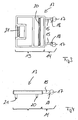
- die Schutzeinrichtung der
Fig. 2 in Draufsicht; und - Fig. 4:
- die Schutzeinrichtung der
Fig. 2 in Seitenansicht. -
Fig. 1 zeigt eine perspektivische Ansicht eines erfindungsgemäßen, als Datenbuchse ausgebildeten elektrischen Steckverbinders 10. - Der Steckverbinder 10 verfügt über ein Gehäuse 11, in welchem eine nichtdargestellte Verbindungseinrichtung positioniert ist. An einer Seite des Gehäuses 11 ist eine Steckeraufnahmeöffnung 12 ausgebildet, über die ein Datenstecker in das Gehäuse 11 zumindest abschnittsweise einführbar ist, um denselben mit der im Gehäuse 11 positionierten Verbindungseinrichtung zu kontaktieren.
- Bei dem über die Steckeraufnahmeöffnung 12 in das Gehäuse 11 einzuführenden Datenstecker kann es sich z. B. um einen RJ45-Datenstecker handeln, wobei dann die Steckeraufnahmeöffnung 12 eine an den RJ45-Datenstecker angepasste Kontur aufweist. Es sei darauf hingewiesen, dass die Erfindung nicht auf RJ45-Datenbuchsen zur Aufnahme von RJ45-Datensteckern beschränkt ist, vielmehr kann die Erfindung auch bei anderen elektrischen Datenbuchsen zum Einsatz kommen.
- Dann, wenn über die Steckeraufnahmeöffnung 12 kein Datenstecker in das Gehäuse 11 der Datenbuchse 10 eingeführt ist, ist die Steckeraufnahmeöffnung 12 offen, wobei dann über die Steckeraufnahmeöffnung 12 Verschmutzungen wie z. B. Staub in das Gehäuse 11 eindringen und in den Bereich der Verbindungseinrichtung gelangen können. Da die Verbindungseinrichtung Kontaktfedern und Platinen umfasst, ist dieselbe gegenüber solchen Verschmutzungen empfindlich, sodass ein Bedarf besteht, die Verbindungseinrichtung einer Datenbuchse gegenüber Verschmutzung zu schützen.
- Erfindungsgemäß umfasst der elektrische Steckverbinder 10 eine Schutzeinrichtung 13, mit der dann, wenn in die Steckeraufnahmeöffnung 12 des Gehäuses 11 kein Datenstecker eingeführt ist, die Steckeraufnahmeöffnung 12 verschlossen werden kann, um so die im Gehäuse 11 positionierte Verbindungseinrichtung vor Verschmutzung zu schützen.
- Die Schutzeinrichtung 13 ist gegenüber dem Gehäuse 11 als separate Baugruppe ausgebildet und verfügt über einen elastischen Anbindungsbereich 14, der im gezeigten Ausführungsbeispiel von elastischen, stabartigen Vorsprüngen 15 gebildet ist.
- Über den elastischen Anbindungsbereich 14 ist die Schutzeinrichtung 13 mit dem Gehäuse 11 der Datenbuchse 10 verbunden, wobei die Schutzeinrichtung 13 durch Verschwenken um den elastischen Anbindungsbereich 14 zwischen einer ersten Position, in der dieselbe die Steckeraufnahmeöffnung 12 freigibt, und einer zweiten Position, in welcher dieselbe die Steckeraufnahmeöffnung 12 verschließt, verlagerbar ist.
- Im gezeigten Ausführungsbeispiel greifen die stabartigen Vorsprünge 15, welche den elastischen Anbindungsbereich 14 der Schutzeinrichtung 13 bilden, in Ausnehmungen 16 des Gehäuses 11 ein, die benachbart zur Steckeraufnahmeöffnung 12 ausgebildet ist. Dabei sind die Ausnehmungen 16 derart konturiert, dass die stabartigen Vorsprünge 15 nach einem elastischen Zusammendrücken bzw. Aufeinanderzubewegen derselben über an Enden derselben ausgebildete Aufdickungen 17 in erste, innere Abschnitte die Ausnehmungen 16 eingefädelt werden können, wobei nach dem Einfädeln die stabartigen Vorsprünge 15 aufgrund ihrer Elastizität sich auseinanderbewegen und in äußere Abschnitte der Ausnehmungen 16 gelangen, die einen geringeren Querschnitt als die inneren Abschnitte der Ausnehmungen 16 und als die Aufdickungen 17 aufweisen. Hierdurch wird die Schutzeinrichtung 13 unverlierbar am Gehäuse 11 des Steckverbinders 10 befestigt.
- Wie insbesondere
Fig. 2 entnommen werden kann, sind beiden stabartigen Vorsprüngen 15, die den elastischen Anbindungsbereich 14 der Schutzeinrichtung 13 bilden, benachbart zu den Aufdickungen 17 Solltrennstellen 18 zugeordnet, über die eine Schutzeinrichtung 13, die unvelierbar am Gehäuse 11 des Steckverbinders 10 befestigt ist, insbesondere dann unter Aufhebung der Unverlierbarkeit vom Gehäuse 11 getrennt werden kann, wenn die Ausnehmungen 16 des Gehäuses 11 aufgrund der Einbausituation des Steckverbinders 10 nicht mehr zugänglich sind. In diesem Fall kann dann der Anbindungsbereich 14 im Bereich der Solltrennstellen 18 durchtrennt werden, wobei auch im abgetrennten Zustand die Schutzeinrichtung 13 zum Verschließen der Steckeraufnahmeöffnung 12 verwendet werden kann. Das Durchtrennen der Solltrennstellen erfolgt werkzeuglos. - Gegenüberliegend zum bzw. angrenzend an den elastischen Anbindungsbereich 14 verfügt die Schutzeinrichtung 13 über einen Verschlussbereich 19, der dann, wenn die Schutzeinrichtung 13 die zweite Position einnimmt, die Steckeraufnahmeöffnung 12 des Steckverbinders 10 verschließt. Dem Verschlussbereich 19 sind im gezeigten Ausführungsbeispiel zwei Dichtlippen 20, 21 zugeordnet, die dann, wenn die Schutzeinrichtung 13 die zweite Position einnimmt, die Steckeraufnahmeöffnung 12 nach außen abdichten. Die Dichtlippen 20, 21 sind dabei an die Kontur der Steckeraufnahmeöffnung 12 des Gehäuses 11 des Steckverbinders 10 angepasst.
- Vorzugsweise ist die gesamte Schutzeinrichtung 13 einstückig ausgebildet und aus einem elastischen Werkstoff, z. B. aus TPU, gefertigt. Dies erlaubt eine besonders kostengünstige Ausführung der Schutzeinrichtung 13.
-
- 10
- elektrischer Steckverbinder
- 11
- Gehäuse
- 12
- Steckeraufnahmeöffnung
- 13
- Schutzeinrichtung
- 14
- elastischer Anbindungsbereich
- 15
- stabartiger Vorsprung
- 16
- Ausnehmung
- 17
- Aufdickung
- 18
- Solltrennstelle
- 19
- Verschlussbereich
- 20
- Dichtlippe
- 21
- Dichtlippe
Claims (13)
- Elektrischer Steckverbinder, nämlich Datenbuchse zur kontaktierenden Aufnahme mindestens eines Datensteckers, mit einem Gehäuse, das eine Steckeraufnahmeöffnung definiert, wobei über die Steckeraufnahmeöffnung ein Abschnitt eines Datenstecker in das Gehäuse einführbar mit einer im Gehäuse positionierten Verbindungseinrichtung kontaktierbar, gekennzeichnet durch eine Schutzeinrichtung (13), um dann, wenn in die Steckeraufnahmeöffnung (12) des Gehäuses (11) kein Datenstecker eingeführt ist, die im Gehäuse (11) positionierte Verbindungseinrichtung vor Verschmutzung zu schützen, wobei die Schutzeinrichtung (13) einen elastischen Anbindungsbereich (14) aufweist, über den die Schutzeinrichtung (13) mit dem Gehäuse (11) verbunden ist, wobei die Schutzeinrichtung (13) durch Verschwenken um den elastischen Anbindungsbereich (14) zwischen einer ersten Position, in der dieselbe die Steckeraufnahmeöffnung (12) freigibt, und einer zweiten Position, in der dieselbe die Steckeraufnahmeöffnung verschließt, verlagerbar ist.
- Steckverbinder nach Anspruch 1, dadurch gekennzeichnet, dass die Schutzeinrichtung (13) gegenüber dem Gehäuse (11) als separate Baugruppe ausgebildet ist.
- Steckverbinder nach Anspruch 1 oder 2, dadurch gekennzeichnet, dass die Schutzeinrichtung (13) dann, wenn der elastische Anbindungsbereich (14) derselben in mindestens eine benachbart zur Steckeraufnahmeöffnung (12) ausgebildete Ausnehmung (16) des Gehäuses (11) eingreift, unverlierbar am Gehäuses (11) befestigt ist.
- Steckverbinder nach Anspruch 3, dadurch gekennzeichnet, dass der elastische Anbindungsbereich (14) der Schutzeinrichtung (13) mindestens eine Solltrennstelle (18) aufweist, um die Schutzeinrichtung (13) unter Aufhebung der Unverlierbarkeit vom Gehäuse (11) zu trennen.
- Steckverbinder nach einem der Ansprüche 1 bis 4, dadurch gekennzeichnet, dass der elastische Anbindungsbereich (14) von vorzugsweise zwei stabartigen Vorsprüngen (15) gebildet ist, die mit jeweils einem Abschnitt in benachbart zur Steckeraufnahmeöffnung (12) ausgebildete Ausnehmungen (16) des Gehäuses (11) eingreifen.
- Steckverbinder nach Anspruch 5, dadurch gekennzeichnet, dass die Ausnehmungen (16) des Gehäuses (11) derart konturiert sind, dass die stabartigen Vorsprünge (15) nach einem Aufeinanderzubewegen derselben über Aufdickungen (17) derselben in innere Abschnitte der Ausnehmungen (16) einfädelbar sind, wobei nach dem Einfädeln die stabartigen Vorsprünge (15) aufgrund ihrer Elastizität sich auseinanderbewegen und in äußere Abschnitte der Ausnehmungen (16) gelangen, die einen geringeren Querschnitt als die inneren Abschnitte und als die Aufdickungen (17) aufweisen.
- Steckverbinder nach Anspruch 5 oder 6, dadurch gekennzeichnet, dass jedem stabartigen Vorsprüngen (15) eine Sollbruchstelle (18) zugeordnet ist.
- Steckverbinder nach einem der Ansprüche 1 bis 7, dadurch gekennzeichnet, dass die Schutzeinrichtung (13) einstückig ist.
- Steckverbinder nach einem der Ansprüche 1 bis 8, dadurch gekennzeichnet, dass die Schutzeinrichtung (13) insgesamt elastisch ist.
- Steckverbinder nach einem der Ansprüche 1 bis 9, dadurch gekennzeichnet, dass die Schutzeinrichtung (13) angrenzend zum Anbindungsbereich (14) einen Verschlussbereich (19) aufweist, der dann, wenn die Schutzeinrichtung die zweite Position einnimmt, die Steckeraufnahmeöffnung (12) verschließt.
- Steckverbinder nach Anspruch 10, dadurch gekennzeichnet, dass der einen Verschlussbereich (19) mindestens eine Dichtlippe (20, 21)aufweist, die an die Kontur der Steckeraufnahmeöffnung (12) des Gehäuses (11) angepasst ist.
- Schutzvorrichtung für einen als Datenbuchse ausgebildeten elektrischen Steckverbinder, um dann, wenn in eine Steckeraufnahmeöffnung eines Gehäuses der Datenbuchse kein Datenstecker eingeführt ist, die Steckeraufnahmeöffnung zu verschließen und vor Verschmutzung zu schützen, mit einem elastischen Anbindungsbereich (14), über den die Schutzeinrichtung mit dem Gehäuse (11) verbindbar ist, wobei die Schutzeinrichtung durch Verschwenken um den elastischen Anbindungsbereich (14) zwischen einer ersten Position, in der dieselbe die Steckeraufnahmeöffnung (12) freigibt, und einer zweiten Position, in der dieselbe die Steckeraufnahmeöffnung verschließt, verlagerbar ist.
- Schutzvorrichtung nach Anspruch 12, gekennzeichnet durch Merkmale nach einem oder mehreren der Ansprüche 2 bis 11.
Applications Claiming Priority (1)
| Application Number | Priority Date | Filing Date | Title |
|---|---|---|---|
| DE200720013266 DE202007013266U1 (de) | 2007-09-20 | 2007-09-20 | Elektrischer Steckverbinder |
Publications (3)
| Publication Number | Publication Date |
|---|---|
| EP2040341A2 true EP2040341A2 (de) | 2009-03-25 |
| EP2040341A3 EP2040341A3 (de) | 2010-12-15 |
| EP2040341B1 EP2040341B1 (de) | 2014-08-06 |
Family
ID=38721713
Family Applications (1)
| Application Number | Title | Priority Date | Filing Date |
|---|---|---|---|
| EP20080014608 Not-in-force EP2040341B1 (de) | 2007-09-20 | 2008-08-18 | Elektrischer Steckverbinder |
Country Status (2)
| Country | Link |
|---|---|
| EP (1) | EP2040341B1 (de) |
| DE (1) | DE202007013266U1 (de) |
Citations (2)
| Publication number | Priority date | Publication date | Assignee | Title |
|---|---|---|---|---|
| WO2001052364A1 (en) | 2000-01-14 | 2001-07-19 | Panduit Corp. | Low crosstalk modular communication connector |
| US20060014410A1 (en) | 2004-07-13 | 2006-01-19 | Caveney Jack E | Communications connector with flexible printed circuit board |
Family Cites Families (5)
| Publication number | Priority date | Publication date | Assignee | Title |
|---|---|---|---|---|
| JP3033690B2 (ja) * | 1996-08-14 | 2000-04-17 | 埼玉日本電気株式会社 | 電子機器のコネクタカバー固定構造 |
| JP3227425B2 (ja) * | 1998-03-11 | 2001-11-12 | 株式会社ケンウッド | ジャックキャップ |
| US20020119697A1 (en) * | 2000-12-27 | 2002-08-29 | Wen-Yao Chan | Mobile phone connector |
| JP2005228756A (ja) * | 2004-02-10 | 2005-08-25 | Nec Access Technica Ltd | 電子機器の端子保護カバー構造、端子保護カバー実装方法。 |
| FR2897230B1 (fr) * | 2006-02-03 | 2008-04-04 | Legrand France | Dispositif d'obturation perfectionne a volet mobile |
-
2007
- 2007-09-20 DE DE200720013266 patent/DE202007013266U1/de not_active Expired - Lifetime
-
2008
- 2008-08-18 EP EP20080014608 patent/EP2040341B1/de not_active Not-in-force
Patent Citations (2)
| Publication number | Priority date | Publication date | Assignee | Title |
|---|---|---|---|---|
| WO2001052364A1 (en) | 2000-01-14 | 2001-07-19 | Panduit Corp. | Low crosstalk modular communication connector |
| US20060014410A1 (en) | 2004-07-13 | 2006-01-19 | Caveney Jack E | Communications connector with flexible printed circuit board |
Also Published As
| Publication number | Publication date |
|---|---|
| EP2040341A3 (de) | 2010-12-15 |
| EP2040341B1 (de) | 2014-08-06 |
| DE202007013266U1 (de) | 2007-11-22 |
Similar Documents
| Publication | Publication Date | Title |
|---|---|---|
| EP1524731B1 (de) | Steckergehäuse mit verbesserter Kabelabdichtung | |
| EP1796225B1 (de) | Vorrichtung für ein axial verschiebbares Steckerkabel in einem Steckergehäuse | |
| EP3127194B1 (de) | Mehrpoliges elektrisches steckverbinderteil | |
| DE69415951T2 (de) | Verbinderanordnung | |
| DE202016107070U1 (de) | Wasserdichte Konnektoranordnung | |
| EP2530784B1 (de) | Elektrische Anschlussvorrichtung mit einem Rückhaltemittel zur Positionierung einer Kontaktfeder in einem Grundzustand | |
| DE102014110696A1 (de) | Mehrstufiger, ineinandergreifender elektro-steckverbinder mit einrastsicherungsmechanismus | |
| DE102014110279B3 (de) | Steckverbinder | |
| WO2011128008A1 (de) | Steckverbinder | |
| WO2012095089A2 (de) | Vorrichtung zur fixierung eines kabels an einen kabelabgangsstutzen | |
| DE202007017488U1 (de) | Steckeranordnung | |
| WO2010130400A1 (de) | Rundsteckverbinder für industrieanwendungen | |
| EP2040341B1 (de) | Elektrischer Steckverbinder | |
| DE202017006800U1 (de) | Innenliegende Zugentlastung für einen Steckverbinder | |
| DE102015104833B3 (de) | Elektrisches/elektronisches Installationsgerät | |
| DE102012111125B4 (de) | RJ45-Stecker und Steckverbinderanordnung mit Positionierungselement | |
| DE102016201328A1 (de) | Schraubkontakt, Leitungsverbindungssystem, Hochvoltsystem und Fahrzeug damit | |
| DE102009048481B4 (de) | Elektrischer Steckverbinder | |
| DE20106297U1 (de) | Elektrische Steckverbindungseinrichtung | |
| DE202014101341U1 (de) | Schutzvorrichtung und Steckeranordnung | |
| DE102014012335A1 (de) | Elektrisches Gerät | |
| DE2046922A1 (de) | Lampensockel | |
| EP1720222B1 (de) | Steckverbinder, insbesondere für Airbag-Zündsysteme | |
| EP1209768B1 (de) | Kabelanschluss- oder -verbindungseinrichtung | |
| EP1548895A2 (de) | Bausatz zum Erstellen eines elektrischen Steckverbinders |
Legal Events
| Date | Code | Title | Description |
|---|---|---|---|
| PUAI | Public reference made under article 153(3) epc to a published international application that has entered the european phase |
Free format text: ORIGINAL CODE: 0009012 |
|
| AK | Designated contracting states |
Kind code of ref document: A2 Designated state(s): AT BE BG CH CY CZ DE DK EE ES FI FR GB GR HR HU IE IS IT LI LT LU LV MC MT NL NO PL PT RO SE SI SK TR |
|
| AX | Request for extension of the european patent |
Extension state: AL BA MK RS |
|
| PUAL | Search report despatched |
Free format text: ORIGINAL CODE: 0009013 |
|
| AK | Designated contracting states |
Kind code of ref document: A3 Designated state(s): AT BE BG CH CY CZ DE DK EE ES FI FR GB GR HR HU IE IS IT LI LT LU LV MC MT NL NO PL PT RO SE SI SK TR |
|
| AX | Request for extension of the european patent |
Extension state: AL BA MK RS |
|
| 17P | Request for examination filed |
Effective date: 20110607 |
|
| AKX | Designation fees paid |
Designated state(s): AT BE BG CH CY CZ DE DK EE ES FI FR GB GR HR HU IE IS IT LI LT LU LV MC MT NL NO PL PT RO SE SI SK TR |
|
| 17Q | First examination report despatched |
Effective date: 20111024 |
|
| REG | Reference to a national code |
Ref country code: DE Ref legal event code: R079 Ref document number: 502008012071 Country of ref document: DE Free format text: PREVIOUS MAIN CLASS: H01R0013453000 Ipc: H01R0013447000 |
|
| RIC1 | Information provided on ipc code assigned before grant |
Ipc: H01R 13/453 20060101ALI20131202BHEP Ipc: H01R 13/447 20060101AFI20131202BHEP |
|
| GRAP | Despatch of communication of intention to grant a patent |
Free format text: ORIGINAL CODE: EPIDOSNIGR1 |
|
| INTG | Intention to grant announced |
Effective date: 20140115 |
|
| GRAS | Grant fee paid |
Free format text: ORIGINAL CODE: EPIDOSNIGR3 |
|
| GRAP | Despatch of communication of intention to grant a patent |
Free format text: ORIGINAL CODE: EPIDOSNIGR1 |
|
| GRAA | (expected) grant |
Free format text: ORIGINAL CODE: 0009210 |
|
| INTG | Intention to grant announced |
Effective date: 20140619 |
|
| AK | Designated contracting states |
Kind code of ref document: B1 Designated state(s): AT BE BG CH CY CZ DE DK EE ES FI FR GB GR HR HU IE IS IT LI LT LU LV MC MT NL NO PL PT RO SE SI SK TR |
|
| REG | Reference to a national code |
Ref country code: GB Ref legal event code: FG4D Free format text: NOT ENGLISH |
|
| REG | Reference to a national code |
Ref country code: AT Ref legal event code: REF Ref document number: 681408 Country of ref document: AT Kind code of ref document: T Effective date: 20140815 Ref country code: CH Ref legal event code: EP |
|
| REG | Reference to a national code |
Ref country code: IE Ref legal event code: FG4D Free format text: LANGUAGE OF EP DOCUMENT: GERMAN |
|
| REG | Reference to a national code |
Ref country code: DE Ref legal event code: R096 Ref document number: 502008012071 Country of ref document: DE Effective date: 20140918 |
|
| PGFP | Annual fee paid to national office [announced via postgrant information from national office to epo] |
Ref country code: FR Payment date: 20140917 Year of fee payment: 7 Ref country code: GB Payment date: 20140929 Year of fee payment: 7 |
|
| REG | Reference to a national code |
Ref country code: NL Ref legal event code: VDEP Effective date: 20140806 |
|
| REG | Reference to a national code |
Ref country code: LT Ref legal event code: MG4D |
|
| PG25 | Lapsed in a contracting state [announced via postgrant information from national office to epo] |
Ref country code: PT Free format text: LAPSE BECAUSE OF FAILURE TO SUBMIT A TRANSLATION OF THE DESCRIPTION OR TO PAY THE FEE WITHIN THE PRESCRIBED TIME-LIMIT Effective date: 20141209 Ref country code: BG Free format text: LAPSE BECAUSE OF FAILURE TO SUBMIT A TRANSLATION OF THE DESCRIPTION OR TO PAY THE FEE WITHIN THE PRESCRIBED TIME-LIMIT Effective date: 20141106 Ref country code: FI Free format text: LAPSE BECAUSE OF FAILURE TO SUBMIT A TRANSLATION OF THE DESCRIPTION OR TO PAY THE FEE WITHIN THE PRESCRIBED TIME-LIMIT Effective date: 20140806 Ref country code: LT Free format text: LAPSE BECAUSE OF FAILURE TO SUBMIT A TRANSLATION OF THE DESCRIPTION OR TO PAY THE FEE WITHIN THE PRESCRIBED TIME-LIMIT Effective date: 20140806 Ref country code: ES Free format text: LAPSE BECAUSE OF FAILURE TO SUBMIT A TRANSLATION OF THE DESCRIPTION OR TO PAY THE FEE WITHIN THE PRESCRIBED TIME-LIMIT Effective date: 20140806 Ref country code: SE Free format text: LAPSE BECAUSE OF FAILURE TO SUBMIT A TRANSLATION OF THE DESCRIPTION OR TO PAY THE FEE WITHIN THE PRESCRIBED TIME-LIMIT Effective date: 20140806 Ref country code: NO Free format text: LAPSE BECAUSE OF FAILURE TO SUBMIT A TRANSLATION OF THE DESCRIPTION OR TO PAY THE FEE WITHIN THE PRESCRIBED TIME-LIMIT Effective date: 20141106 Ref country code: GR Free format text: LAPSE BECAUSE OF FAILURE TO SUBMIT A TRANSLATION OF THE DESCRIPTION OR TO PAY THE FEE WITHIN THE PRESCRIBED TIME-LIMIT Effective date: 20141107 |
|
| PGFP | Annual fee paid to national office [announced via postgrant information from national office to epo] |
Ref country code: DE Payment date: 20140929 Year of fee payment: 7 |
|
| PG25 | Lapsed in a contracting state [announced via postgrant information from national office to epo] |
Ref country code: PL Free format text: LAPSE BECAUSE OF FAILURE TO SUBMIT A TRANSLATION OF THE DESCRIPTION OR TO PAY THE FEE WITHIN THE PRESCRIBED TIME-LIMIT Effective date: 20140806 Ref country code: HR Free format text: LAPSE BECAUSE OF FAILURE TO SUBMIT A TRANSLATION OF THE DESCRIPTION OR TO PAY THE FEE WITHIN THE PRESCRIBED TIME-LIMIT Effective date: 20140806 Ref country code: NL Free format text: LAPSE BECAUSE OF FAILURE TO SUBMIT A TRANSLATION OF THE DESCRIPTION OR TO PAY THE FEE WITHIN THE PRESCRIBED TIME-LIMIT Effective date: 20140806 Ref country code: CY Free format text: LAPSE BECAUSE OF FAILURE TO SUBMIT A TRANSLATION OF THE DESCRIPTION OR TO PAY THE FEE WITHIN THE PRESCRIBED TIME-LIMIT Effective date: 20140806 Ref country code: LV Free format text: LAPSE BECAUSE OF FAILURE TO SUBMIT A TRANSLATION OF THE DESCRIPTION OR TO PAY THE FEE WITHIN THE PRESCRIBED TIME-LIMIT Effective date: 20140806 Ref country code: IS Free format text: LAPSE BECAUSE OF FAILURE TO SUBMIT A TRANSLATION OF THE DESCRIPTION OR TO PAY THE FEE WITHIN THE PRESCRIBED TIME-LIMIT Effective date: 20141206 |
|
| REG | Reference to a national code |
Ref country code: CH Ref legal event code: PL |
|
| PG25 | Lapsed in a contracting state [announced via postgrant information from national office to epo] |
Ref country code: SK Free format text: LAPSE BECAUSE OF FAILURE TO SUBMIT A TRANSLATION OF THE DESCRIPTION OR TO PAY THE FEE WITHIN THE PRESCRIBED TIME-LIMIT Effective date: 20140806 Ref country code: DK Free format text: LAPSE BECAUSE OF FAILURE TO SUBMIT A TRANSLATION OF THE DESCRIPTION OR TO PAY THE FEE WITHIN THE PRESCRIBED TIME-LIMIT Effective date: 20140806 Ref country code: CZ Free format text: LAPSE BECAUSE OF FAILURE TO SUBMIT A TRANSLATION OF THE DESCRIPTION OR TO PAY THE FEE WITHIN THE PRESCRIBED TIME-LIMIT Effective date: 20140806 Ref country code: BE Free format text: LAPSE BECAUSE OF NON-PAYMENT OF DUE FEES Effective date: 20140831 Ref country code: CH Free format text: LAPSE BECAUSE OF NON-PAYMENT OF DUE FEES Effective date: 20140831 Ref country code: RO Free format text: LAPSE BECAUSE OF FAILURE TO SUBMIT A TRANSLATION OF THE DESCRIPTION OR TO PAY THE FEE WITHIN THE PRESCRIBED TIME-LIMIT Effective date: 20140806 Ref country code: EE Free format text: LAPSE BECAUSE OF FAILURE TO SUBMIT A TRANSLATION OF THE DESCRIPTION OR TO PAY THE FEE WITHIN THE PRESCRIBED TIME-LIMIT Effective date: 20140806 Ref country code: LI Free format text: LAPSE BECAUSE OF NON-PAYMENT OF DUE FEES Effective date: 20140831 Ref country code: IT Free format text: LAPSE BECAUSE OF FAILURE TO SUBMIT A TRANSLATION OF THE DESCRIPTION OR TO PAY THE FEE WITHIN THE PRESCRIBED TIME-LIMIT Effective date: 20140806 |
|
| REG | Reference to a national code |
Ref country code: DE Ref legal event code: R097 Ref document number: 502008012071 Country of ref document: DE |
|
| REG | Reference to a national code |
Ref country code: IE Ref legal event code: MM4A |
|
| PG25 | Lapsed in a contracting state [announced via postgrant information from national office to epo] |
Ref country code: MC Free format text: LAPSE BECAUSE OF FAILURE TO SUBMIT A TRANSLATION OF THE DESCRIPTION OR TO PAY THE FEE WITHIN THE PRESCRIBED TIME-LIMIT Effective date: 20140806 |
|
| PLBE | No opposition filed within time limit |
Free format text: ORIGINAL CODE: 0009261 |
|
| STAA | Information on the status of an ep patent application or granted ep patent |
Free format text: STATUS: NO OPPOSITION FILED WITHIN TIME LIMIT |
|
| 26N | No opposition filed |
Effective date: 20150507 |
|
| PG25 | Lapsed in a contracting state [announced via postgrant information from national office to epo] |
Ref country code: IE Free format text: LAPSE BECAUSE OF NON-PAYMENT OF DUE FEES Effective date: 20140818 |
|
| REG | Reference to a national code |
Ref country code: AT Ref legal event code: MM01 Ref document number: 681408 Country of ref document: AT Kind code of ref document: T Effective date: 20140818 |
|
| PG25 | Lapsed in a contracting state [announced via postgrant information from national office to epo] |
Ref country code: AT Free format text: LAPSE BECAUSE OF NON-PAYMENT OF DUE FEES Effective date: 20140818 Ref country code: SI Free format text: LAPSE BECAUSE OF FAILURE TO SUBMIT A TRANSLATION OF THE DESCRIPTION OR TO PAY THE FEE WITHIN THE PRESCRIBED TIME-LIMIT Effective date: 20140806 |
|
| REG | Reference to a national code |
Ref country code: DE Ref legal event code: R119 Ref document number: 502008012071 Country of ref document: DE |
|
| GBPC | Gb: european patent ceased through non-payment of renewal fee |
Effective date: 20150818 |
|
| REG | Reference to a national code |
Ref country code: FR Ref legal event code: ST Effective date: 20160429 |
|
| PG25 | Lapsed in a contracting state [announced via postgrant information from national office to epo] |
Ref country code: MT Free format text: LAPSE BECAUSE OF FAILURE TO SUBMIT A TRANSLATION OF THE DESCRIPTION OR TO PAY THE FEE WITHIN THE PRESCRIBED TIME-LIMIT Effective date: 20140806 |
|
| PG25 | Lapsed in a contracting state [announced via postgrant information from national office to epo] |
Ref country code: HU Free format text: LAPSE BECAUSE OF FAILURE TO SUBMIT A TRANSLATION OF THE DESCRIPTION OR TO PAY THE FEE WITHIN THE PRESCRIBED TIME-LIMIT; INVALID AB INITIO Effective date: 20080818 Ref country code: DE Free format text: LAPSE BECAUSE OF NON-PAYMENT OF DUE FEES Effective date: 20160301 Ref country code: GB Free format text: LAPSE BECAUSE OF NON-PAYMENT OF DUE FEES Effective date: 20150818 Ref country code: LU Free format text: LAPSE BECAUSE OF NON-PAYMENT OF DUE FEES Effective date: 20140818 Ref country code: TR Free format text: LAPSE BECAUSE OF FAILURE TO SUBMIT A TRANSLATION OF THE DESCRIPTION OR TO PAY THE FEE WITHIN THE PRESCRIBED TIME-LIMIT Effective date: 20140806 |
|
| PG25 | Lapsed in a contracting state [announced via postgrant information from national office to epo] |
Ref country code: FR Free format text: LAPSE BECAUSE OF NON-PAYMENT OF DUE FEES Effective date: 20150831 |