EP2040260A2 - Plattenvorrichtung - Google Patents
Plattenvorrichtung Download PDFInfo
- Publication number
- EP2040260A2 EP2040260A2 EP08016470A EP08016470A EP2040260A2 EP 2040260 A2 EP2040260 A2 EP 2040260A2 EP 08016470 A EP08016470 A EP 08016470A EP 08016470 A EP08016470 A EP 08016470A EP 2040260 A2 EP2040260 A2 EP 2040260A2
- Authority
- EP
- European Patent Office
- Prior art keywords
- follower
- cam
- traverse chassis
- disk device
- cam groove
- Prior art date
- Legal status (The legal status is an assumption and is not a legal conclusion. Google has not performed a legal analysis and makes no representation as to the accuracy of the status listed.)
- Granted
Links
- 239000011347 resin Substances 0.000 claims description 9
- 229920005989 resin Polymers 0.000 claims description 9
- 230000003287 optical effect Effects 0.000 description 26
- 238000010586 diagram Methods 0.000 description 2
- 238000004519 manufacturing process Methods 0.000 description 2
- 230000000694 effects Effects 0.000 description 1
- 230000001747 exhibiting effect Effects 0.000 description 1
- 230000037431 insertion Effects 0.000 description 1
- 238000003780 insertion Methods 0.000 description 1
- 238000000465 moulding Methods 0.000 description 1
Images


Classifications
-
- G—PHYSICS
- G11—INFORMATION STORAGE
- G11B—INFORMATION STORAGE BASED ON RELATIVE MOVEMENT BETWEEN RECORD CARRIER AND TRANSDUCER
- G11B17/00—Guiding record carriers not specifically of filamentary or web form, or of supports therefor
- G11B17/02—Details
- G11B17/022—Positioning or locking of single discs
- G11B17/028—Positioning or locking of single discs of discs rotating during transducing operation
- G11B17/0288—Positioning or locking of single discs of discs rotating during transducing operation by means for moving the turntable or the clamper towards the disk
Definitions
- the present invention relates to a disk device, in particular, a disk device in which a turntable, coacting with a clamper to clamp a disk and rotating the disk, is mounted on a traverse chassis and in which a countermeasure for suppressing reading error of the disk due to self-induced vibration of the traverse chassis is applied.
- one end of the traverse chassis is supported on a fixed frame (loader chassis), and the traverse chassis is enabled to tiltingly move (enabled to move reciprocatingly) along a rectilinear path with a position of support by the fixed frame as a pivot.
- the turntable is mounted, along with an optical element, such as an optical pickup, etc., on the traverse chassis, and when the traverse chassis moves onward along with the turntable, the disk, mounted on the turntable, is clamped by coaction of the turntable and a clamper, attached to the fixed frame and waiting at a fixed position.
- the disk, clamped by the clamper and the turntable rotates together with the turntable, and during the rotation, the disk is optically processed by the optical pickup.
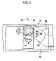
- FIG. 5 is a schematic front view of the cam mechanism 10 of a disk device described in JP-A-2003-223776 .
- the cam mechanism 10 is constituted of a follower 20, disposed on the traverse chassis (not shown), a cam plate 30, moved forward and in reverse as indicated by arrows X in a direction orthogonal to a direction of reciprocal movement of another end of the traverse chassis, a cam groove 31, formed in the cam plate 30 and making the follower 20 slide to make the other end of the traverse chassis move reciprocatingly along a rectilinear path, and an auxiliary guiding member 40, having straight guiding surfaces 41 that make the follower 20 slide when the cam plate 30 is moved forward and in reverse to guide the reciprocal movement of the follower 20.
- the cam groove 31 of the camplate 30 includes a horizontal first riding surface 32, onto which the follower 20 rides at its onward movement limit position, a horizontal second riding surface 33, onto which the follower 20 rides at its return movement limit position, and an inclined surface 34, making the first and second riding surfaces 32 and 33 continuous.
- the follower 20 of the cam mechanism 10 that rides on the first riding surface 32 of the cam groove 31 is clamped by the guiding surfaces 41 as shown in FIG. 5 .
- the follower 20 and the other end of the traverse chassis provided with the follower 20 are thus provisionally positioned in the reciprocal movement direction (vertical direction), indicated by arrows A in the figure, and a direction (left/right direction), indicated by arrows B in the figure and orthogonal to the reciprocal movement direction of the traverse chassis.
- the follower 20 of the cam mechanism 10 riding on the first riding surface 32 of the cam groove 31, is desirably clamped by the guiding surfaces 41 and positioned accurately in the mutually orthogonal directions indicated by the arrows A and B.
- This problem is known to occur especially readily during reproduction of a disk with a mass eccentricity, etc.
- optical reading errors occurring readily due to deformation of the first riding surface 32 of the cam groove 34, the guiding surfaces 41 of the auxiliary guiding member 40, etc., caused by influence of heat generated by the vibration of the follower accompanying the self-induced vibration of the traverse chassis, and it is known that the possibility of this occurring is especially high under a high temperature environment, such as 65°C temperature and 80% humidity, or after high temperature storage, such as 120 hours of storage under 65°C temperature and 80% humidity.
- the follower is provided by a vibration absorbing action based on an action of an elastic member. Therefore, the disk device with which optical reading errors by the optical pickup can be made less likely to occur by preventing lowering of a vibration absorbing property of the elastic member of the follower, riding on the riding surface of the cam groove.
- a configuration of the disk device can be achieved by simply improving a configuration of a portion of the cam mechanism of the disk device described with reference to FIG. 5 and without adding extra parts.
- a disk device including: a traverse chassis, one end of which is configured to be movable between a first position and a second position in a first direction, the traverse chassis adapted to mount a turntable for a disk medium thereon; a cam member, formed with a cam groove configured to move in a second direction orthogonal to the first direction and having a first end and a second end; a cam follower, protruded from the one end of the traverse chassis, and fitted with the cam groove so as to be movable between the first end and the second end in accordance with the movement of the cam member; a guide member, having a guide face configured to guide the cam follower in the first direction in cooperation with the cam member, thereby causing the one end of the traverse chassis to move between the first position and the second position; and an urging member, configured to urge the cam follower against an inner wall of the cam groove and the guide face when the cam follower is placed in the first end of the cam groove.
- the follower may include: a protrusion, formed on the traverse chassis; an elastic member, provided on the protrusion; and a cover, provided on the elastic member and fitted with the cam groove.
- the self-induced vibration of the traverse chassis is thus absorbed efficiently by the elastic member and this helps in making optical reading errors by the optical pickup less likely to occur. Also, deformation of the riding surface of the cam groove, the guiding surface of the auxiliary guiding member, etc., caused by influence of heat generated by the vibration of the follower accompanying the self-induced vibration of the traverse chassis, is suppressed and optical reading errors are made less likely to occur.
- the urging member may be configured to urge the cam follower in an oblique direction with respect to both the inner wall and the guide face.
- the urging member may be monolithically formed with the guide member.
- the urging member may be comprised of resin.
- the guide member may be monolithically formed with a fixed frame supporting the traverse chassis, and guide member may be comprised of resin.
- the present invention provides an effect of enabling the vibration of the follower due to self-induced vibration of the traverse chassis to be suppressed and enabling the action of making optical reading errors by the optical pickup less likely to occur to be obtained by simply improving the configuration of a portion of the cam mechanism and without adding extra parts.
- FIG. 1 is a plan view of a general configuration of a disk device according to an embodiment of the present invention as viewed from a rear side
- FIG. 2 is a schematic exploded perspective view of a traverse chassis 50 and a cam mechanism 10 used in the disk device of FIG. 1
- FIG. 3 is a schematic front view of the cam mechanism 10
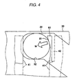
- FIG. 4 is an enlarged explanatory diagram of a principal portion of FIG. 3 .
- 60 is a fixed frame, serving as a loader chassis and formed to a rectangular frame form, and with respect to the fixed frame 60, a disk tray 70, indicated by hypothetical lines, is enabled to move in an ejection/insertion direction (front/rear direction) indicated by arrows L.
- a mounting portion for a circular disk is formed in a recessed manner on an upper surface of the disk tray 70, and a disk mounted on the mounting portion is inserted and ejected with respect to a set position substantially at a center of the fixed frame 60 by movement of the disk tray 70 in the direction of the arrows L.
- a traverse chassis 50 carrying a turntable 62, is attached to the fixed frame 60.
- One end 51 in a longitudinal direction (matching the front/rear direction) of the traverse chassis 50 is attached to the fixed frame 60, and another end (free end) 52 at an opposite side in the longitudinal direction is made tiltable in a vertical direction about attachment locations A as pivots.
- cushioning members 53 are interposed at the attachment locations A to prevent impact from the fixed frame 60, etc., from being transmitted to the traverse chassis 50.
- Each cushioning member 53 is constituted of vibration-proof rubber and is held by the traverse chassis 50 by being fitted in a split hole 54, formed in the one end 51 of the traverse chassis 50 as shown in FIG.
- the cam mechanism 10, shown in FIG. 2 includes a follower 20, disposed on the other end of the traverse chassis 50, a cam plate 30, a cam groove 31, formed in the cam plate 30, and an auxiliary guiding member 40.
- the follower 20 includes a protrusion 21, disposed at a central portion of the other end of the traverse chassis 50, a cylindrical cover 22, externally fitted onto the protrusion 21 and sliding along both the cam groove 31 and guiding surfaces 41 of the auxiliary guiding member 40 during reciprocal movement, and a tubular elastic member 23, interposed between the protrusion 21 and the cover 22 and exhibiting a damper action.
- the cam plate 30 is enabled to move forward and in reverse in a direction (left/right direction indicated by arrows X) orthogonal to the reciprocal movement direction of the other end 52 of the traverse chassis 50.
- the guiding surfaces 41 of the auxiliary guiding member 40 make the follower 20 slide when the cam plate 30 moves forward and in reverse and guides straight, reciprocal movement of the follower 20.
- a clamper (not shown) is attached to the fixed frame 60, and the clamper is enabled to coact with the turntable 62, mounted on the traverse chassis 50, to clamp the disk, and the disk, clamped by the clamper and the turntable 62, is made to rotate along with the turntable 62.
- the follower 20 of the cam mechanism 10 riding on a first riding surface 32 of the cam groove 31, is clamped by the guiding surfaces 41 as shown in FIG. 3 .
- the follower 20 and the other end 52 of the traverse chassis 50 provided with the follower 20 are thus provisionally positioned in the reciprocal movement direction (vertical direction) of the traverse chassis 50 and the direction (left/right direction) orthogonal to the reciprocal movement direction of the traverse chassis 50.
- a urging member that presses the follower 20, riding onto the first riding surface 32 of the cam groove 31, and thereby makes the first riding surface 32 and the guiding surfaces 41 of the auxiliary guiding member 40 elastically press the follower 20.
- the urging member is a urging member 80, shown in FIGS. 2 to 4 .
- the urging member 80 is a resin spring, molded integrally of resin and molded integral to the auxiliary guiding member 40, formed of resin, by making the auxiliary guidingmember 40 have a slit 42 extending along a guiding surface 41 of the auxiliary guidingmember 40. More specifically as shown in FIGS.
- the urging member 80 constituted of the resin spring, is formed at a position of elastically contacting the follower 20, riding on the first riding surface 32 of the cam groove 31, and the urging member 80 is provided with an inclined surface 81.
- the inclined surface 81 pressing a single location of an outer circumferential surface of the cover 22 of the follower 20, riding on the first riding surface 32 of the cam groove 31, the cover 22 is pressed in a direction inclined with respect to both the first riding surface 32 and the guiding surface 41 as indicated by an arrow M.
- the follower 20 riding on the first riding surface 32 of the cam groove 31, is elastically pressed by both the first riding surface 32 and the guiding surface 41 and the cover 22 is thereby positioned accurately without play in the two mutually orthogonal directions. Consequently, a possibility for an entirety of the follower 20 vibrating and the vibration absorbing action of the elastic member 23 of the follower 20 not being exhibited efficiently when the traverse chassis 50 undergoes self-induced vibration during disk rotation is lessened, and the vibration absorbing property of the elastic member 23 of the follower 20 when the traverse chassis 50 undergoes self-induced vibration is thus improved.
- the follower 20 includes the elastic member 23 that exhibits the vibration absorbing property
- the elastic member 23 is not necessarily required. That is, a configuration is also possible where the follower is formed of a protrusion, protruded from the other end of the traverse chassis, the protrusion is slidably engaged with the cam groove of the cam plate, and the protrusion is guided along a rectilinear path by the guiding surfaces of the auxiliary guiding member.
Landscapes
- Feeding And Guiding Record Carriers (AREA)
- Moving Of The Head For Recording And Reproducing By Optical Means (AREA)
Applications Claiming Priority (1)
| Application Number | Priority Date | Filing Date | Title |
|---|---|---|---|
| JP2007244891A JP2009076150A (ja) | 2007-09-21 | 2007-09-21 | ディスク装置 |
Publications (3)
| Publication Number | Publication Date |
|---|---|
| EP2040260A2 true EP2040260A2 (de) | 2009-03-25 |
| EP2040260A3 EP2040260A3 (de) | 2009-05-27 |
| EP2040260B1 EP2040260B1 (de) | 2014-01-08 |
Family
ID=40011184
Family Applications (1)
| Application Number | Title | Priority Date | Filing Date |
|---|---|---|---|
| EP08016470.0A Expired - Fee Related EP2040260B1 (de) | 2007-09-21 | 2008-09-18 | Plattenvorrichtung |
Country Status (3)
| Country | Link |
|---|---|
| US (1) | US8037489B2 (de) |
| EP (1) | EP2040260B1 (de) |
| JP (1) | JP2009076150A (de) |
Families Citing this family (2)
| Publication number | Priority date | Publication date | Assignee | Title |
|---|---|---|---|---|
| JP2011096344A (ja) * | 2009-11-02 | 2011-05-12 | Funai Electric Co Ltd | ディスク装置のトラバースユニット保持機構 |
| JP2014207042A (ja) | 2013-04-15 | 2014-10-30 | 船井電機株式会社 | 光ディスク装置 |
Citations (2)
| Publication number | Priority date | Publication date | Assignee | Title |
|---|---|---|---|---|
| US5317464A (en) | 1991-06-28 | 1994-05-31 | Syquest Technology, Inc. | Removable cartridge disk drive with cartridge interlocking and spindle motor telescoping mechanisms |
| US20030142611A1 (en) | 2002-01-29 | 2003-07-31 | Funai Electric Co., Ltd. | Disk apparatus |
Family Cites Families (9)
| Publication number | Priority date | Publication date | Assignee | Title |
|---|---|---|---|---|
| KR100379050B1 (ko) * | 1998-07-02 | 2003-04-07 | 마쯔시다덴기산교 가부시키가이샤 | 디스크 장치 |
| WO2003085662A1 (fr) * | 2002-04-08 | 2003-10-16 | Citizen Watch Co., Ltd. | Lecteur de disque |
| JP2004152390A (ja) * | 2002-10-30 | 2004-05-27 | Orion Denki Kk | ディスク装置の動力切り替え機構 |
| JP3792643B2 (ja) * | 2002-12-06 | 2006-07-05 | 三菱電機株式会社 | 光ディスク装置 |
| JP4245468B2 (ja) * | 2003-12-10 | 2009-03-25 | 三菱電機株式会社 | 光ディスク装置 |
| JP2006127659A (ja) * | 2004-10-29 | 2006-05-18 | Orion Denki Kk | トラバースユニットのガタツキ防止機構を備えたディスク装置 |
| JP4260844B2 (ja) * | 2005-01-07 | 2009-04-30 | 三菱電機株式会社 | 光ディスク装置 |
| JP2007172787A (ja) * | 2005-12-26 | 2007-07-05 | Funai Electric Co Ltd | ディスク装置 |
| JP2007188582A (ja) * | 2006-01-12 | 2007-07-26 | Sony Corp | ディスクドライブ装置及びベースユニット |
-
2007
- 2007-09-21 JP JP2007244891A patent/JP2009076150A/ja active Pending
-
2008
- 2008-09-18 US US12/212,719 patent/US8037489B2/en not_active Expired - Fee Related
- 2008-09-18 EP EP08016470.0A patent/EP2040260B1/de not_active Expired - Fee Related
Patent Citations (2)
| Publication number | Priority date | Publication date | Assignee | Title |
|---|---|---|---|---|
| US5317464A (en) | 1991-06-28 | 1994-05-31 | Syquest Technology, Inc. | Removable cartridge disk drive with cartridge interlocking and spindle motor telescoping mechanisms |
| US20030142611A1 (en) | 2002-01-29 | 2003-07-31 | Funai Electric Co., Ltd. | Disk apparatus |
Also Published As
| Publication number | Publication date |
|---|---|
| US20090083776A1 (en) | 2009-03-26 |
| EP2040260B1 (de) | 2014-01-08 |
| US8037489B2 (en) | 2011-10-11 |
| JP2009076150A (ja) | 2009-04-09 |
| EP2040260A3 (de) | 2009-05-27 |
Similar Documents
| Publication | Publication Date | Title |
|---|---|---|
| US8037489B2 (en) | Disk device | |
| US7444653B2 (en) | Disc unit and damper mechanism therefor | |
| CN103137149A (zh) | 盘驱动装置 | |
| US8060899B2 (en) | Disk device | |
| CN100412958C (zh) | 盘驱动单元以及盘记录和/或复制设备 | |
| US20110321069A1 (en) | Disc-clamping mechanism and disc driving apparatus | |
| US7950028B2 (en) | Disk apparatus with improved optical pickup mount | |
| EP1684273B1 (de) | Optischer Lesekopf | |
| CN101785058B (zh) | 盘片装置 | |
| US8151287B2 (en) | Optical pickup feed device for sliding optical pickup | |
| US20100054101A1 (en) | Lens driving apparatus | |
| JP3427666B2 (ja) | ディスク装置 | |
| US8245248B2 (en) | Optical disk apparatus having guide shaft adjusting mechanism | |
| JPWO2005088619A1 (ja) | 光学ピックアップ装置 | |
| CN101572104B (zh) | 头驱动装置及光盘装置 | |
| US8332881B2 (en) | Optical disc apparatus with support part configured to reduce vibrations | |
| JP2008186529A (ja) | ピックアップトラバース装置および光ディスク装置 | |
| KR101220692B1 (ko) | 광기기 장치 | |
| JP3858438B2 (ja) | ディスクドライブ装置 | |
| JP4246144B2 (ja) | ディスククランプ装置 | |
| US8117630B2 (en) | Optical disk player with head feeding mechanism | |
| KR20120078424A (ko) | 광기기 장치 | |
| JPWO2010070923A1 (ja) | ディスク装置 | |
| KR20110100554A (ko) | 일체형 디스크 구동 모듈 | |
| JP2004234774A (ja) | 対物レンズ駆動装置、光ピックアップ及びディスクドライブ装置 |
Legal Events
| Date | Code | Title | Description |
|---|---|---|---|
| PUAI | Public reference made under article 153(3) epc to a published international application that has entered the european phase |
Free format text: ORIGINAL CODE: 0009012 |
|
| AK | Designated contracting states |
Kind code of ref document: A2 Designated state(s): AT BE BG CH CY CZ DE DK EE ES FI FR GB GR HR HU IE IS IT LI LT LU LV MC MT NL NO PL PT RO SE SI SK TR |
|
| AX | Request for extension of the european patent |
Extension state: AL BA MK RS |
|
| PUAL | Search report despatched |
Free format text: ORIGINAL CODE: 0009013 |
|
| AK | Designated contracting states |
Kind code of ref document: A3 Designated state(s): AT BE BG CH CY CZ DE DK EE ES FI FR GB GR HR HU IE IS IT LI LT LU LV MC MT NL NO PL PT RO SE SI SK TR |
|
| AX | Request for extension of the european patent |
Extension state: AL BA MK RS |
|
| 17P | Request for examination filed |
Effective date: 20091127 |
|
| AKX | Designation fees paid |
Designated state(s): DE FR GB |
|
| GRAP | Despatch of communication of intention to grant a patent |
Free format text: ORIGINAL CODE: EPIDOSNIGR1 |
|
| INTG | Intention to grant announced |
Effective date: 20130730 |
|
| GRAS | Grant fee paid |
Free format text: ORIGINAL CODE: EPIDOSNIGR3 |
|
| GRAA | (expected) grant |
Free format text: ORIGINAL CODE: 0009210 |
|
| AK | Designated contracting states |
Kind code of ref document: B1 Designated state(s): DE FR GB |
|
| REG | Reference to a national code |
Ref country code: GB Ref legal event code: FG4D |
|
| REG | Reference to a national code |
Ref country code: DE Ref legal event code: R096 Ref document number: 602008029703 Country of ref document: DE Effective date: 20140220 |
|
| REG | Reference to a national code |
Ref country code: DE Ref legal event code: R097 Ref document number: 602008029703 Country of ref document: DE |
|
| PGFP | Annual fee paid to national office [announced via postgrant information from national office to epo] |
Ref country code: DE Payment date: 20140926 Year of fee payment: 7 |
|
| PLBE | No opposition filed within time limit |
Free format text: ORIGINAL CODE: 0009261 |
|
| STAA | Information on the status of an ep patent application or granted ep patent |
Free format text: STATUS: NO OPPOSITION FILED WITHIN TIME LIMIT |
|
| PGFP | Annual fee paid to national office [announced via postgrant information from national office to epo] |
Ref country code: GB Payment date: 20140917 Year of fee payment: 7 Ref country code: FR Payment date: 20140811 Year of fee payment: 7 |
|
| 26N | No opposition filed |
Effective date: 20141009 |
|
| REG | Reference to a national code |
Ref country code: DE Ref legal event code: R097 Ref document number: 602008029703 Country of ref document: DE Effective date: 20141009 |
|
| REG | Reference to a national code |
Ref country code: DE Ref legal event code: R119 Ref document number: 602008029703 Country of ref document: DE |
|
| GBPC | Gb: european patent ceased through non-payment of renewal fee |
Effective date: 20150918 |
|
| REG | Reference to a national code |
Ref country code: FR Ref legal event code: ST Effective date: 20160531 |
|
| PG25 | Lapsed in a contracting state [announced via postgrant information from national office to epo] |
Ref country code: DE Free format text: LAPSE BECAUSE OF NON-PAYMENT OF DUE FEES Effective date: 20160401 Ref country code: GB Free format text: LAPSE BECAUSE OF NON-PAYMENT OF DUE FEES Effective date: 20150918 |
|
| PG25 | Lapsed in a contracting state [announced via postgrant information from national office to epo] |
Ref country code: FR Free format text: LAPSE BECAUSE OF NON-PAYMENT OF DUE FEES Effective date: 20150930 |