EP2039633A2 - Sheet overlap detection apparatus and sheet overlap detection method - Google Patents
Sheet overlap detection apparatus and sheet overlap detection method Download PDFInfo
- Publication number
- EP2039633A2 EP2039633A2 EP08075764A EP08075764A EP2039633A2 EP 2039633 A2 EP2039633 A2 EP 2039633A2 EP 08075764 A EP08075764 A EP 08075764A EP 08075764 A EP08075764 A EP 08075764A EP 2039633 A2 EP2039633 A2 EP 2039633A2
- Authority
- EP
- European Patent Office
- Prior art keywords
- amplifier
- output
- value
- amplification factor
- overlap detection
- Prior art date
- Legal status (The legal status is an assumption and is not a legal conclusion. Google has not performed a legal analysis and makes no representation as to the accuracy of the status listed.)
- Withdrawn
Links
Images


Classifications
-
- B—PERFORMING OPERATIONS; TRANSPORTING
- B65—CONVEYING; PACKING; STORING; HANDLING THIN OR FILAMENTARY MATERIAL
- B65H—HANDLING THIN OR FILAMENTARY MATERIAL, e.g. SHEETS, WEBS, CABLES
- B65H7/00—Controlling article feeding, separating, pile-advancing, or associated apparatus, to take account of incorrect feeding, absence of articles, or presence of faulty articles
- B65H7/02—Controlling article feeding, separating, pile-advancing, or associated apparatus, to take account of incorrect feeding, absence of articles, or presence of faulty articles by feelers or detectors
- B65H7/06—Controlling article feeding, separating, pile-advancing, or associated apparatus, to take account of incorrect feeding, absence of articles, or presence of faulty articles by feelers or detectors responsive to presence of faulty articles or incorrect separation or feed
- B65H7/12—Controlling article feeding, separating, pile-advancing, or associated apparatus, to take account of incorrect feeding, absence of articles, or presence of faulty articles by feelers or detectors responsive to presence of faulty articles or incorrect separation or feed responsive to double feed or separation
-
- G—PHYSICS
- G01—MEASURING; TESTING
- G01B—MEASURING LENGTH, THICKNESS OR SIMILAR LINEAR DIMENSIONS; MEASURING ANGLES; MEASURING AREAS; MEASURING IRREGULARITIES OF SURFACES OR CONTOURS
- G01B17/00—Measuring arrangements characterised by the use of infrasonic, sonic or ultrasonic vibrations
- G01B17/02—Measuring arrangements characterised by the use of infrasonic, sonic or ultrasonic vibrations for measuring thickness
-
- B—PERFORMING OPERATIONS; TRANSPORTING
- B65—CONVEYING; PACKING; STORING; HANDLING THIN OR FILAMENTARY MATERIAL
- B65H—HANDLING THIN OR FILAMENTARY MATERIAL, e.g. SHEETS, WEBS, CABLES
- B65H2511/00—Dimensions; Position; Numbers; Identification; Occurrences
- B65H2511/50—Occurence
- B65H2511/52—Defective operating conditions
- B65H2511/524—Multiple articles, e.g. double feed
-
- B—PERFORMING OPERATIONS; TRANSPORTING
- B65—CONVEYING; PACKING; STORING; HANDLING THIN OR FILAMENTARY MATERIAL
- B65H—HANDLING THIN OR FILAMENTARY MATERIAL, e.g. SHEETS, WEBS, CABLES
- B65H2515/00—Physical entities not provided for in groups B65H2511/00 or B65H2513/00
- B65H2515/82—Sound; Noise
-
- B—PERFORMING OPERATIONS; TRANSPORTING
- B65—CONVEYING; PACKING; STORING; HANDLING THIN OR FILAMENTARY MATERIAL
- B65H—HANDLING THIN OR FILAMENTARY MATERIAL, e.g. SHEETS, WEBS, CABLES
- B65H2553/00—Sensing or detecting means
- B65H2553/30—Sensing or detecting means using acoustic or ultrasonic elements
-
- B—PERFORMING OPERATIONS; TRANSPORTING
- B65—CONVEYING; PACKING; STORING; HANDLING THIN OR FILAMENTARY MATERIAL
- B65H—HANDLING THIN OR FILAMENTARY MATERIAL, e.g. SHEETS, WEBS, CABLES
- B65H2557/00—Means for control not provided for in groups B65H2551/00 - B65H2555/00
- B65H2557/30—Control systems architecture or components, e.g. electronic or pneumatic modules; Details thereof
Definitions
- the present invention relates to a sheet overlap detection apparatus and sheet overlap detection method using an ultrasonic wave.
- the paper sheet overlap detection is normally done using a projector and a photodetector.
- a projector is arranged on the lower surface side of the feeding table near the front lay.
- a through-hole is formed at a predetermined portion of the feeding table so as to face the light-emitting unit of the projector.
- a photodetector is arranged on the upper surface side of the feeding table so as to face the through-hole. That is, the projector projects light in the thickness direction of a paper sheet to be fed.
- the photodetector receives the light transmitted through the fed paper sheet.
- the light is converted into an electrical signal.
- An output level corresponding to the received light amount that is obtained as the electrical signal is compared with a preset determination level. Overlap of the fed paper sheets is detected based on the comparison result (Japanese Patent Laid-Open Nos. 2-178145 and 63-290746 ).
- the overlap detection apparatus using an ultrasonic wave comprises an ultrasonic transmitter which transmits an ultrasonic wave, and an ultrasonic receiver which receives the ultrasonic wave from the ultrasonic transmitter. On the basis of the reception level of the ultrasonic wave received by the ultrasonic receiver, the apparatus detects overlap of fed paper sheets which pass between the ultrasonic transmitter and the ultrasonic receiver.
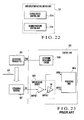
- Fig. 23 shows an example of the conventional overlap detection apparatus using an ultrasonic wave.
- the overlap detection apparatus comprises an ultrasonic transmitter 501, an ultrasonic receiver 502, and a control unit 503 attached to the ultrasonic transmitter 501 and the ultrasonic receiver 502.
- the control unit 503 comprises a processing unit 503A, ultrasonic oscillation circuit 503B, and amplification circuit 503C.
- the amplification circuit 503C comprises a first amplifier (fixed amplifier) AMP501 and a second amplifier (variable amplifier) AMP502.
- the ultrasonic oscillation circuit 503B supplies a driving frequency f to the ultrasonic transmitter 501.
- the ultrasonic transmitter 501 Upon receiving the driving frequency f from the ultrasonic oscillation circuit 503B, the ultrasonic transmitter 501 emits an ultrasonic wave of output level determined by the driving frequency f ( Fig. 24 ).
- the ultrasonic receiver 502 receives the ultrasonic wave emitted from the ultrasonic transmitter 501 and sends a reception output RV corresponding to the ultrasonic wave reception amount to the amplification circuit 503C.
- the amplification circuit 503C amplifies the reception output RV from the ultrasonic receiver 502 and sends, to the processing unit 503A, output values AP501 and AP502 representing the ultrasonic wave reception level in the ultrasonic receiver 502. Based on the output values AP501 and AP502 from the amplification circuit 503C, the processing unit 503A detects overlap of fed paper sheets 504 which pass between the ultrasonic transmitter 501 and the
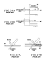
- Figs. 25A and 25B show the changes of the output values AP501 and AP502 from the amplification circuit 503C when one paper sheet 504 is fed.
- Figs. 26A and 26B show the changes of the output values AP501 and AP502 from the amplification circuit 503C when two paper sheets 504 are fed.
- the output value AP501 of the amplification circuit 503C is defined to be a set value V1s when no fed paper sheet 504 is sandwiched between the ultrasonic transmitter 501 and the ultrasonic receiver 502.
- the output value AP502 of the amplification circuit 503C is defined to be a set value V2s when one fed paper sheet 504 is sandwiched between the ultrasonic transmitter 501 and the ultrasonic receiver 502. Values about 80% of the set values V1s and V2s are set as threshold values Vth1 and Vth2.
- the fed paper sheet 504 which is inserted between the ultrasonic transmitter 501 and the ultrasonic receiver 502 reflects the ultrasonic wave. Hence, the ultrasonic wave reception amount in the ultrasonic receiver 502 decreases. In this case, when one paper sheet 504 is inserted between the ultrasonic transmitter 501 and the ultrasonic receiver 502, the attenuation amount of the ultrasonic wave reception amount in the ultrasonic receiver 502 is small ( Fig. 27A ).
- the output value AP501 of the amplification circuit 503C is smaller than the threshold value Vth1 ( Fig. 25A : point t1).
- the output value AP502 of the amplification circuit 503C keeps the threshold value Vth2 or more ( Fig. 25B : point t1).
- the processing unit 503A monitors the output values AP501 and AP502 from the amplification circuit 503C and detects overlap of the fed paper sheets 504 when the output value AP501 is smaller than the threshold value Vth1, and the output value AP502 is also smaller than the threshold value Vth2.
- the amplification factor GA of the amplifier AMP502 in the amplification circuit 503C is limited. This makes it impossible to detect specialty paper such as microflute having a high ultrasonic wave attenuation factor, and degrades the detection accuracy.
- the present invention has been made to solve the above-described problems, and has as its object to provide a sheet overlap detection apparatus and sheet overlap detection method capable of accurately detecting overlap of even specialty paper having a high ultrasonic wave attenuation factor.
- a sheet overlap detection apparatus comprising an ultrasonic transmitter which transmits an ultrasonic wave, an ultrasonic receiver which receives the ultrasonic wave from the ultrasonic transmitter, a first amplifier which amplifies an output from the ultrasonic receiver, a second amplifier which is configured to freely change an amplification factor and amplifies an output from the first amplifier, a third amplifier which amplifies an output from the second amplifier, amplification factor control means for changing the amplification factor of the second amplifier, first overlap detection monitor output decision means for deciding the output from the second amplifier as a sheet overlap detection monitor output when the amplification factor control means adjusts the amplification factor of the second amplifier, and an output value of the second amplifier has become almost equal to a first set value while one sheet is sandwiched between the ultrasonic transmitter and the ultrasonic receiver, second overlap detection monitor output decision means for deciding an output from the third amplifier as a sheet overlap detection monitor output when the amplification factor control means adjusts the amplification
- a sheet overlap detection method comprising the steps of causing an ultrasonic transmitter to transmit an ultrasonic wave, causing an ultrasonic receiver to receive the ultrasonic wave from the ultrasonic transmitter, causing a first amplifier to amplify an output from the ultrasonic receiver, causing a second amplifier to amplify an output from the first amplifier, causing a third amplifier to amplify an output from the second amplifier, adjusting an amplification factor of the second amplifier, deciding the output from the second amplifier as a sheet overlap detection monitor output when the amplification factor of the second amplifier is adjusted, and an output value of the second amplifier has become almost equal to a first set value while one sheet is sandwiched between the ultrasonic transmitter and the ultrasonic receiver, deciding an output from the third amplifier as a sheet overlap detection monitor output when the amplification factor of the second amplifier is adjusted, and the output value of the second amplifier has not become almost equal to the first set value, but an output value of the third amplifier has become almost equal to a second set value while one sheet
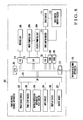
- Fig. 1 shows an overlap detection apparatus according to the first embodiment of the present invention.
- the overlap detection apparatus comprises an ultrasonic transmitter (ultrasonic transmission sensor) 1 which transmits an ultrasonic wave, an ultrasonic receiver (ultrasonic reception sensor) 2 which receives the ultrasonic wave from the ultrasonic transmitter 1, and a control unit 3 attached to the ultrasonic transmitter 1 and the ultrasonic receiver 2.
- the control unit 3 comprises a processing unit 3A, ultrasonic oscillation circuit 3B, and amplification circuit 3C.
- the amplification circuit 3C comprises a first amplifier AMP1 which amplifies the output from the ultrasonic receiver 2, a second amplifier AMP2 which amplifies the output from the first amplifier AMP1, and a third amplifier AMP3 which amplifies the output from the second amplifier AMP2.
- the first and third amplifiers AMP1 and AMP3 are fixed amplifiers having fixed amplification factors.
- the second amplifier AMP2 is a variable amplifier capable of freely changing the amplification factor.
- the ultrasonic oscillation circuit 3B supplies a driving frequency f to the ultrasonic transmitter 1.
- the ultrasonic transmitter 1 Upon receiving the driving frequency f from the ultrasonic oscillation circuit 3B, the ultrasonic transmitter 1 emits an ultrasonic wave of output level determined by the driving frequency f.
- the ultrasonic receiver 2 receives the ultrasonic wave emitted from the ultrasonic transmitter 1 and sends a reception output RV corresponding to the ultrasonic wave reception amount to the amplification circuit 3C.
- the amplification circuit 3C amplifies the reception output RV from the ultrasonic receiver 2 and sends, to the processing unit 3A, output values AP1, AP2, and AP3 representing the ultrasonic wave reception levels in the ultrasonic receiver 2. Based on the output values AP1, AP2, and AP3 from the amplification circuit 3C, the processing unit 3A detects overlap of fed paper sheets 4 which pass between the ultrasonic transmitter 1 and the ultrasonic receiver 2.
- the amplification circuit 3C includes the third amplifier AMP3.
- the third amplifier AMP3 is connected to the output of the second amplifier AMP2.
- the output value AP3 from the third amplifier AMP3 is supplied to the processing unit 3A.
- the processing unit 3A includes an overlap detection monitor output & amplification factor decision unit 30.
- the overlap detection monitor output & amplification factor decision unit 30 decides one of the output value AP2 of the second amplifier AMP2 and the output value AP3 of the third amplifier AMP3 as an overlap detection monitor output and also decides an overlap detection amplification factor GA of the second amplifier AMP2.
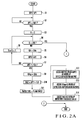
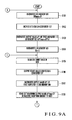
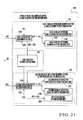
- Figs. 2A and 2B show the overlap detection monitor output & amplification factor decision processing operation of the overlap detection monitor output & amplification factor decision unit 30 in the processing unit 3A.
- the overlap detection monitor output & amplification factor decision unit 30 is implemented as a processing operation of a CPU according to a program stored in a memory of the processing unit 3A.
- the processing unit 3A has a switch SW1 to instruct the overlap detection monitor output & amplification factor decision processing operation.
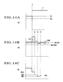
- the ultrasonic transmitter 1 is emitting an ultrasonic wave upon receiving the driving frequency f from the ultrasonic oscillation circuit 3B. Additionally, one paper sheet 4 is fed between the ultrasonic receiver 2 and the ultrasonic transmitter 1 which is emitting the ultrasonic wave.
- the processing unit 3A receives the output value AP1 from the first amplifier AMP1 ( Fig. 2A : step S1) and compares it with a threshold value Vth1 (step S2). If the output value AP1 of the first amplifier AMP1 is smaller than the threshold value Vth1 (YES in step S2, Fig. 3A : point t1), it is determined that one fed paper sheet 4 is sandwiched between the ultrasonic transmitter 1 and the ultrasonic receiver 2.
- the processing unit 3A Upon determining that one fed paper sheet 4 is sandwiched between the ultrasonic transmitter 1 and the ultrasonic receiver 2 (YES in step S2), the processing unit 3A sets a count value N to 0 (step S3). The processing unit confirms that the count value N does not satisfy N > 255 (NO in step S4) and sets the amplification factor GA of the second amplifier AMP2 to GA 0 (minimum value) (step S5, Fig. 3C : point t1).
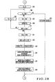
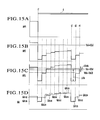
- the processing unit sets the paper type to plain paper (step S11), decides the output from the second amplifier AMP2 as the overlap detection monitor output (step S12), decides GAsp as the overlap detection amplification factor (step S13), and decides the threshold value Vth2 as the overlap detection threshold value (step S14).
- the process advances to step S15 ( Fig. 2B ) to set the count value N to 0.
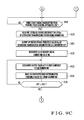
- the processing unit confirms that the count value N does not satisfy N > 255 (NO in step S16) and sets the amplification factor GA of the second amplifier AMP2 to GA 0 (minimum value) (step S17, Fig. 4D : point t2).
- the processing unit sets the paper type to specialty paper (step S23), decides the output from the third amplifier AMP3 as the overlap detection monitor output (step S24), decides GAsp as the overlap detection amplification factor (step S25), and decides the threshold value Vth3 as the overlap detection threshold value (step S26).
- the process advances to step S27 to determine that detection is disabled. That is, if the output value AP3 of the third amplifier AMP3 is not equal to the set value V3s, either, the processing unit determines that overlap detection at an appropriate accuracy is disabled, and displays, e.g., an error message.
- the output from the second amplifier AMP2 is decided as the overlap detection monitor output.
- the output from the third amplifier AMP3 is decided as the overlap detection monitor output. This makes it possible to accurately detect overlap of paper sheets in a wide range including specialty paper.
- Fig. 5 shows the functional blocks of the overlap detection monitor output & amplification factor decision unit 30 in the processing unit 3A.
- the overlap detection monitor output & amplification factor decision unit 30 comprises an amplification factor control unit 31, first overlap detection monitor output & amplification factor decision unit 32, and second overlap detection monitor output & amplification factor decision unit 33.
- the amplification factor control unit 31 raises the amplification factor GA of the second amplifier AMP2 stepwise from GA 0 to GA 255 .
- the amplification factor control unit 31 performs the processes in, e.g., steps S5 and S17.
- the first overlap detection monitor output & amplification factor decision unit 32 decides the output of the second amplifier AMP2 as the overlap detection monitor output when the output value AP2 of the second amplifier AMP2 is recognized to be almost equal to the set value V2s halfway through the process of causing the amplification factor control unit 31 to raise the amplification factor GA of the second amplifier AMP2 stepwise from GA 0 to GA 255 .
- the first overlap detection monitor output & amplification factor decision unit 32 also receives the amplification factor GA N of the second amplifier AMP2 at that time and decides the received amplification factor GA N as the overlap detection amplification factor GAsp.
- the first overlap detection monitor output & amplification factor decision unit 32 sends an instruction to the amplification factor control unit 31 to make it again raise the amplification factor GA of the second amplifier AMP2 stepwise from GA 0 to GA 255 .
- the first overlap detection monitor output & amplification factor decision unit 32 comprises a first equivalence determination unit 32A, first overlap detection monitor output decision unit 32B, and first overlap detection amplification factor decision unit 32C.
- the first equivalence determination unit 32A performs the process in, e.g., step S7.
- the first overlap detection monitor output decision unit 32B performs the process in, e.g., step S12.
- the first overlap detection amplification factor decision unit 32C performs the process in, e.g., step S13.
- the second overlap detection monitor output & amplification factor decision unit 33 decides the output from the third amplifier AMP3 as the overlap detection monitor output when the output value AP3 of the third amplifier AMP3 is recognized to be almost equal to the set value V3s halfway through the process of causing the amplification factor control unit 31 to raise the amplification factor GA of the second amplifier AMP2 stepwise from GA 0 to GA 255 .
- the second overlap detection monitor output & amplification factor decision unit 33 also receives the amplification factor GA N of the second amplifier AMP2 at that time and decides the received amplification factor GA N as the overlap detection amplification factor GAsp.
- the second overlap detection monitor output & amplification factor decision unit 33 determines that detection is disabled.
- the second overlap detection monitor output & amplification factor decision unit 33 comprises a second equivalence determination unit 33A, second overlap detection monitor output decision unit 33B, second overlap detection amplification factor decision unit 33C, and detection disable determination unit 33D.
- the second equivalence determination unit 33A performs the process in, e.g., step S19.
- the second overlap detection monitor output decision unit 33B performs the process in, e.g., step S24.
- the second overlap detection amplification factor decision unit 33C performs the process in, e.g., step S25.
- the detection disable determination unit 33D performs the process in, e.g., step S27.
- the amplification factor GA of the second amplifier AMP2 is raised stepwise from GA 0 to GA 255 .
- the amplification factor GA is set to GA 128 first. If the output value AP2 of the second amplifier AMP2 at that time is smaller than the set value V2s, the amplification factor GA is raised to GA 192 .
- the amplification factor GA may be narrowed down in this way until the output value AP2 of the second amplifier AMP2 almost equals the set value V2s. This method will be described later in the second embodiment. This method can greatly speed up the processing as compared to the method of changing the amplification factor GA step by step.
- the amplification factor GA of the second amplifier AMP2 is raised again stepwise from GA 0 to GA 255 , thereby searching for a point where the output value AP3 of the third amplifier AMP3 satisfies AP3 ⁇ V3s.
- the output value AP2 of the second amplifier AMP2 and the output value AP3 of the third amplifier AMP3 are stored while raising the amplification factor GA of the second amplifier AMP2 stepwise from GA 0 to GA 255 .
- the output value AP2 of the second amplifier AMP2 and the output value AP3 of the third amplifier AMP3 corresponding to the amplification factors GA 0 to GA 255 are observed.
- the output from the second amplifier AMP2 is decided as the overlap detection monitor output.
- the output from the third amplifier AMP3 may be decided as the overlap detection monitor output. This obviates changing the amplification factor GA of the second amplifier AMP2 again and speeds up the processing.
- an overlap detection unit 34 in the processing unit 3A detects overlap of the fed paper sheets 4 which pass between the ultrasonic transmitter 1 and the ultrasonic receiver 2.
- FIG. 6 shows an overlap detection apparatus according to the second embodiment of the present invention.
- An overlap detection apparatus 100 is connected to a printing press control apparatus 200 and comprises a CPU 101, ROM 102, RAM 103, input device 104, display device 105, output device 106, VCO (voltage to frequency converter) D/A converter 107, VCO 108, ultrasonic oscillation circuit 109, ultrasonic transmission sensor (ultrasonic transmitter) 110, ultrasonic reception sensor (ultrasonic receiver) 111, first amplifier (fixed amplifier) 112 (AMP1), second amplifier (variable amplifier) 113 (AMP2), third amplifier (fixed amplifier) 114 (AMP3), D/A converter 115 for second amplifier gain adjustment, printing press rotation phase detection counter 116, printing press rotation phase detection rotary encoder 117, A/D converters 118 to 120, interfaces 121 to 128, and memory M.
- Examples of the output device 106 are an FD driver and a printer.
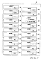
- the memory M comprises a memory M1 for storing a count value N corresponding to the maximum output value of the ultrasonic reception sensor, a memory M2 for storing the maximum output value of the ultrasonic reception sensor, a memory M3 for storing the count value N, a memory M4 for storing the output value of the first amplifier, a memory M5 for storing the optimum driving frequency value of the ultrasonic transmission sensor, a memory M6 for storing the correction value of the count value N, a memory M7 for storing a paper presence determination threshold value, a memory M8 for storing the output value of the second amplifier, a memory M9 for storing an optimum gain value determination reference value, a memory M10 for storing the difference to the optimum gain value determination reference value, a memory M11 for storing the absolute value of the difference to the optimum gain value determination reference value, a memory M12 for storing an optimum gain value determination threshold value, a memory M13 for storing the next correction value of
- the memory M1 stores a count value NRmax corresponding to the maximum output value of the ultrasonic reception sensor.
- the memory M2 stores a maximum output value AP1max of the ultrasonic reception sensor.
- the memory M3 stores the count value N.
- the memory M4 stores an output value AP1 of the first amplifier.
- the memory M5 stores an optimum driving frequency value Nsp of the ultrasonic transmission sensor.
- the memory M6 stores a correction value NC of the count value N.
- the memory M7 stores a paper presence determination threshold value Vth1.
- the memory M8 stores an output value AP2 of the second amplifier.
- the memory M10 stores a difference ⁇ Vs between the output value of the second amplifier and the optimum gain value determination reference value.
- the memory M11 stores an absolute value
- the memory M12 stores an optimum gain value determination threshold value ⁇ Vsth.
- the memory M13 stores a next correction value NC' of the count value N.
- the memory M14 stores "1" when the paper type is plain paper, and "2" for specialty paper.
- the memory M15 stores an optimum gain value NGsp.
- the memory M16 stores an overlap detection threshold value Vth.
- the memory M17 stores an output value AP3 of the third amplifier.
- the memory M18 stores a count value N ⁇ of the printing press rotation phase detection counter.
- the memory M19 stores a printing press rotation phase ⁇ .
- the memory M20 stores an overlap detection phase N ⁇ sp.
- the memory M21 stores a detection output value AP. The contents stored in the memories M1 to M21 will be explained later in association with the description of the overlap detection processing operation.
- Fig. 8 shows the arrangement of the printing press control apparatus 200.
- the printing press control apparatus 200 comprises a CPU 201, print start switch 202, print stop switch 203, overlap detection apparatus reset switch 204, input device 205, display device 206, output device 207, feeding unit 208, first printing unit 209 1 to fourth printing unit 209 4 , drive motor driver 210, drive motor 211, drive motor rotary encoder 212, interfaces 213 to 217, ROM 218, and RAM 219.
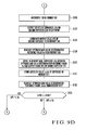
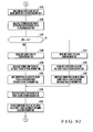
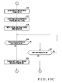
- a processing operation unique to the embodiment, which is executed by the CPU 101 of the overlap detection apparatus 100, will be described below with reference to the flowcharts shown in Figs. 9A to 10C .
- the CPU 101 executes the processing operation in accordance with an overlap detection program stored in the ROM 102.
- the CPU 101 Upon receiving an instruction to start the overlap detection program, the CPU 101 sets the count value NRmax corresponding to the maximum output value of the ultrasonic reception sensor in the memory M1 to 0 ( Fig. 9A : step S101). Next, the CPU outputs "0" to the VCO D/A converter 107 (step S102) so that a driving frequency f from the ultrasonic oscillation circuit 109 to the ultrasonic transmission sensor 110 is set to f 0 . The CPU receives the output value AP1 (AP1 0 ) from the first amplifier 112 via the A/D converter 120 and overwrites it in the memory M2 as the maximum output value APlmax (step S103).
- the CPU 101 sets the count value N in the memory M3 to "1" (step S104), reads out the count value N from the memory M3 (step S105), and outputs it to the VCO D/A converter 107 (step S106).
- the driving frequency f from the ultrasonic oscillation circuit 109 to the ultrasonic transmission sensor 110 is set to f 1 .
- the CPU 101 receives the output value AP1 (AP1 1 ) from the first amplifier 112 at this time via the A/D converter 120 and overwrites it in the memory M4 (step S107).
- the CPU reads out the maximum output value APlmax (AP1 0 ) of the ultrasonic reception sensor at that time from the memory M2 (step S108) and compares it with the output value AP1 (AP1 1 ) of the first amplifier 112 in the memory M4 ( Fig. 9B : step S109). If AP1 is larger than AP1max (YES in step S109), the CPU overwrites AP1 in the memory M2 as APlmax (step S110). In this case, since AP1 1 is larger than AP1 0 , APlmax changes to AP1 1 .
- the CPU reads out the count value N from the memory M3 (step S115) and repeats the processing operation in steps S105 to S116 until the count value N satisfies N > 255 (NO in step S116).
- the process jumps to step S113 to repeat the same processing operation without executing steps S110, S111, and S112.
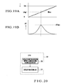
- the driving frequency f to the ultrasonic transmission sensor 110 changes stepwise from f 0 to f 255 (see Fig. 19A ).
- the maximum one of the output values AP1 of the first amplifier 112 obtained in correspondence with the driving frequencies f 0 to f 255 is stored as AP1max (see Fig. 19B ).
- the count value N corresponding to a driving frequency fx upon obtaining the maximum value APlmax is stored in the memory M1 as the count value NRmax corresponding to the maximum output value of the ultrasonic reception sensor.
- step S116 the CPU 101 reads out, from the memory M1, the count value NRmax corresponding to the maximum output value of the ultrasonic reception sensor (step S117) and writes the readout count value NRmax in the memory M5 as the optimum driving frequency value Nsp of the ultrasonic transmission sensor (step S118). That is, the CPU decides f Nsp as the optimum driving frequency of the ultrasonic transmission sensor and writes the optimum driving frequency value Nsp corresponding to the optimum driving frequency f Nsp in the memory M5.
- a driving signal is output to the drive motor driver 210 (step S302) to start operating the printing press.
- a feed start instruction is output to the feeding unit 208 (step S303) to start paper feed to the printing press.
- a print start signal is transmitted to the overlap detection apparatus 100 (step S304).
- a print start instruction is output to the printing units 209 1 to 209 4 ( Fig. 10B : step S307).
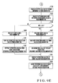
- the CPU 101 of the overlap detection apparatus 100 Upon receiving the print start signal from the printing press control apparatus 200 ( Fig. 9C : YES in step S119), the CPU 101 of the overlap detection apparatus 100 reads out the optimum driving frequency value Nsp of the ultrasonic sensor from the memory M5 (step S120) and outputs the readout optimum driving frequency value Nsp of the ultrasonic sensor to the VCO D/A converter 107 (step S121).
- the driving frequency f from the ultrasonic oscillation circuit 109 to the ultrasonic transmission sensor 110 is set to the optimum driving frequency f Nsp .
- the CPU receives the output value AP1 from the first amplifier 112 (step S123), reads out the paper presence determination threshold value Vth1 from the memory M7 (step S124), and compares the output value AP1 of the first amplifier 112 with the paper presence determination threshold value Vth1 (step S125).
- the CPU 101 repeats the processing in steps S123 to S125.
- the CPU determines that one fed paper sheet 4 is sandwiched between the ultrasonic transmission sensor 110 and the ultrasonic reception sensor 111, and writes "128" in the memory M3 as the count value N ( Fig. 9D : step S126).
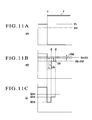
- the CPU also receives the output value AP2 from the second amplifier 113 via the A/D converter 119 ( Fig. 11B : point t1) and writes it in the memory M8 (step S128).
- the CPU reads out the optimum gain value determination reference value Vs from the memory M9 (step S129), subtracts the output value AP2 of the second amplifier 113 from the optimum gain value determination reference value Vs to obtain the difference ⁇ Vs between the output value AP2 of the second amplifier 113 and the optimum gain value determination reference value Vs (step S130), and obtains the absolute value
- the obtained difference ⁇ Vs is written in the memory M10.
- of the difference is written in the memory M11.
- the CPU 101 reads out the optimum gain value determination threshold value ⁇ Vsth from the memory M12 (step S132) and compares it with the absolute value
- step S134 the CPU 101 reads out the output value AP2 of the second amplifier 113 at that time from the memory M8 (step S134), reads out the optimum gain value determination reference value Vs from the memory M9 (step S135), and compares the output value AP2 of the second amplifier 113 with the optimum gain value determination reference value Vs (step S136).
- the CPU also receives the output value AP2 from the second amplifier 113 via the A/D converter 119 ( Fig. 11B : point t2) and writes it in the memory M8 (step S147).
- the CPU reads out the optimum gain value determination reference value Vs from the memory M9 (step S148), subtracts the output value AP2 of the second amplifier 113 from the optimum gain value determination reference value Vs to obtain the difference ⁇ Vs between the output value AP2 of the second amplifier 113 and the optimum gain value determination reference value Vs (step S149), and obtains the absolute value
- the CPU reads out the optimum gain value determination threshold value ⁇ Vsth from the memory M12 (step S151) and compares it with the absolute value
- step S153 the CPU 101 reads out the output value AP2 of the second amplifier 113 at that time from the memory M8 (step S153), reads out the optimum gain value determination reference value Vs from the memory M9 (step S154), and compares the output value AP2 of the second amplifier 113 with the optimum gain value determination reference value Vs (step S155).
- AP2 ⁇ Vs.
- the CPU also receives the output value AP2 from the second amplifier 113 via the A/D converter 119 ( Fig. 11B : point t3) and writes it in the memory M8 (step S147).
- the CPU reads out the optimum gain value determination reference value Vs from the memory M9 (step S148), subtracts the output value AP2 of the second amplifier 113 from the optimum gain value determination reference value Vs to obtain the difference ⁇ Vs between the output value AP2 of the second amplifier 113 and the optimum gain value determination reference value Vs (step S149), and obtains the absolute value
- the CPU reads out the optimum gain value determination threshold value ⁇ Vsth from the memory M12 (step S151) and compares it with the absolute value
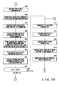
- step S171 the CPU 101 determines that the output value AP2 of the second amplifier 113 is almost equal to the optimum gain value determination reference value Vs (AP2 ⁇ Vs), and writes "1" representing that the fed paper sheet 4 is plain paper in the memory M14 (step S171).
- the CPU reads out the output value AP2 of the second amplifier 113 from the memory M8 (step S174), multiplies the readout output value AP2 of the second amplifier by 0.8 to obtain the overlap detection threshold value Vth, and writes it in the memory M16 (step S175).
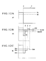
- the CPU also receives the output value AP2 from the second amplifier 113 via the A/D converter 119 ( Fig. 13B : point t2) and writes it in the memory M8 (step S147).
- the CPU reads out the optimum gain value determination reference value Vs from the memory M9 (step S148), subtracts the output value AP2 of the second amplifier 113 from the optimum gain value determination reference value Vs to obtain the difference ⁇ Vs between the output value AP2 of the second amplifier 113 and the optimum gain value determination reference value Vs (step S149), and obtains the absolute value
- the CPU reads out the optimum gain value determination threshold value ⁇ Vsth from the memory M12 (step S151) and compares it with the absolute value
- step S153 the CPU 101 reads out the output value AP2 of the second amplifier 113 at that time from the memory M8 (step S153), reads out the optimum gain value determination reference value Vs from the memory M9 (step S154), and compares the output value AP2 of the second amplifier 113 with the optimum gain value determination reference value Vs (step S155).
- AP2 > Vs.
- the CPU also receives the output value AP2 from the second amplifier 113 via the A/D converter 119 ( Fig. 13B : point t3) and writes it in the memory M8 (step S147).
- the CPU reads out the optimum gain value determination reference value Vs from the memory M9 (step S148), subtracts the output value AP2 of the second amplifier 113 from the optimum gain value determination reference value Vs to obtain the difference ⁇ Vs between the output value AP2 of the second amplifier 113 and the optimum gain value determination reference value Vs (step S149), and obtains the absolute value
- the CPU reads out the optimum gain value determination threshold value ⁇ Vsth from the memory M12 (step S151) and compares it with the absolute value
- step S171 the CPU 101 determines that the output value AP2 of the second amplifier 113 is almost equal to the optimum gain value determination reference value Vs (YES in step S152), and writes "1" representing that the fed paper sheet 4 is plain paper in the memory M14 (step S171).
- the CPU reads out the output value AP2 of the second amplifier 113 from the memory M8 (step S174), multiplies the readout output value AP2 of the second amplifier by 0.8 to obtain the overlap detection threshold value Vth, and writes it in the memory M16 (step S175).
- step S165 After the gain GA is set to "GA 1 ", the correction value NC' of the count value N in step S165 ( Fig. 9H ) is 0.5. Since YES in step S166, the process advances to step S167 to set the correction value NC of the count value to 1. If the count value N ⁇ 0 in step S163, the CPU transmits an error signal to the printing press control apparatus 200 (step S169).
- step S155 Fig. 9G
- step S164 Fig. 9H
- the CPU 101 determines that
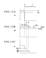
- the CPU receives the output value AP3 from the third amplifier 114 via the A/D converter 118 ( Fig. 15C : point t2) and writes it in the memory M17 (step S179).
- the CPU reads out the optimum gain value determination reference value Vs from the memory M9 (step S180), subtracts the output value AP3 of the third amplifier 114 from the optimum gain value determination reference value Vs to obtain the difference ⁇ Vs between the output value AP3 of the third amplifier 114 and the optimum gain value determination reference value Vs (step S181), and obtains the absolute value
- the obtained difference ⁇ Vs is written in the memory M10.
- of the difference is written in the memory M11.
- the CPU reads out the optimum gain value determination threshold value ⁇ Vsth from the memory M12 (step S183) and compares it with the absolute value
- step S185 the CPU 101 reads out the output value AP3 of the third amplifier 114 at that time from the memory M17 (step S185), reads out the optimum gain value determination reference value Vs from the memory M9 (step S186), and compares the output value AP3 of the third amplifier 114 with the optimum gain value determination reference value Vs (step S187).
- the CPU also receives the output value AP3 from the third amplifier 114 via the A/D converter 118 ( Fig. 15C : point t3) and writes it in the memory M17 (step S198).
- the CPU reads out the optimum gain value determination reference value Vs from the memory M9 (step S199), subtracts the output value AP3 of the third amplifier 114 from the optimum gain value determination reference value Vs to obtain the difference ⁇ Vs between the output value AP3 of the third amplifier 114 and the optimum gain value determination reference value Vs (step S200), and obtains the absolute value
- the CPU reads out the optimum gain value determination threshold value ⁇ Vsth from the memory M12 (step S202) and compares it with the absolute value
- step S204 the CPU 101 reads out the output value AP3 of the third amplifier 114 at that time from the memory M17 (step S204), reads out the optimum gain value determination reference value Vs from the memory M9 (step S205), and compares the output value AP3 of the third amplifier 114 with the optimum gain value determination reference value Vs (step S206).
- AP3 ⁇ Vs.
- the CPU also receives the output value AP3 from the third amplifier 114 via the A/D converter 118 ( Fig. 15C : point t4) and writes it in the memory M17 (step S198).
- the CPU reads out the optimum gain value determination reference value Vs from the memory M9 (step S199), subtracts the output value AP3 of the third amplifier 114 from the optimum gain value determination reference value Vs to obtain the difference ⁇ Vs between the output value AP3 of the third amplifier 114 and the optimum gain value determination reference value Vs (step S200), and obtains the absolute value
- the CPU reads out the optimum gain value determination threshold value ⁇ Vsth from the memory M12 (step S202) and compares it with the absolute value
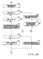
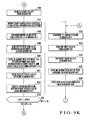
- step S222 the CPU 101 determines that the output value AP3 of the third amplifier 114 is almost equal to the optimum gain value determination reference value Vs (AP3 ⁇ Vs), and writes "2" representing that the fed paper sheet 4 is specialty paper in the memory M14 (step S222).
- the CPU reads out the output value AP3 of the third amplifier 114 from the memory M17 (step S225), multiplies the readout output value AP3 of the third amplifier by 0.8 to obtain the overlap detection threshold value Vth, and writes it in the memory M16 (step S226).
- step S206 determines whether the gain GA of the second amplifier 113 is GA 224 .
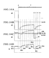
- ⁇ ⁇ Vsth does not hold, and AP3 > Vs holds ( Fig. 16C : point t4).
- the CPU also receives the output value AP3 from the third amplifier 114 via the A/D converter 118 ( Fig. 17C : point t3) and writes it in the memory M17 (step S198).
- the CPU reads out the optimum gain value determination reference value Vs from the memory M9 (step S199), subtracts the output value AP3 of the third amplifier 114 from the optimum gain value determination reference value Vs to obtain the difference ⁇ Vs between the output value AP3 of the third amplifier 114 and the optimum gain value determination reference value Vs (step S200), and obtains the absolute value
- the CPU reads out the optimum gain value determination threshold value ⁇ Vsth from the memory M12 (step S202) and compares it with the absolute value
- step S204 the CPU 101 reads out the output value AP3 of the third amplifier 114 at that time from the memory M17 (step S204), reads out the optimum gain value determination reference value Vs from the memory M9 (step S205), and compares the output value AP3 of the third amplifier 114 with the optimum gain value determination reference value Vs (step S206).
- AP3 > Vs.
- the CPU also receives the output value AP3 from the third amplifier 114 via the A/D converter 118 ( Fig. 17C : point t4) and writes it in the memory M17 (step S198).
- the CPU reads out the optimum gain value determination reference value Vs from the memory M9 (step S199), subtracts the output value AP3 of the third amplifier 114 from the optimum gain value determination reference value Vs to obtain the difference ⁇ Vs between the output value AP3 of the third amplifier 114 and the optimum gain value determination reference value Vs (step S200), and obtains the absolute value
- the CPU reads out the optimum gain value determination threshold value ⁇ Vsth from the memory M12 (step S202) and compares it with the absolute value
- step S222 the CPU 101 determines that the output value AP3 of the third amplifier 114 is almost equal to the optimum gain value determination reference value Vs (YES in step S203), and writes "2" representing that the fed paper sheet 4 is specialty paper in the memory M14 (step S222).
- the CPU reads out the output value AP3 of the third amplifier 114 from the memory M17 (step S225), multiplies the readout output value AP3 of the third amplifier by 0.8 to obtain the overlap detection threshold value Vth, and writes it in the memory M16 (step S226).
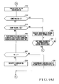
- step S217 After the gain GA is set to "GA 1 ", the correction value NC' of the count value N in step S217 ( Fig. 9M ) is 0.5. Since YES in step S217, the process advances to step S218 to set the correction value NC of the count value to 1. If the count value N ⁇ 0 in step S214, the CPU transmits an error signal to the printing press control apparatus 200 (step S220).
- step S187 Fig. 9J
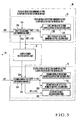
- the CPU 201 of the printing press control apparatus 200 Upon receiving the error signal from the overlap detection apparatus 100 ( Fig. 10A : YES in step S305), the CPU 201 of the printing press control apparatus 200 outputs a feed stop instruction to the feeding unit 208 ( Fig. 10C : step S316) to stop paper feed from the feeding unit 208 to the printing press.
- the CPU also outputs a print stop instruction to the printing units 209 1 to 209 4 (step S317) to cause them to stop printing on paper sheets.
- the CPU also outputs a driving stop signal to the drive motor driver 210 (step S318) to stop the printing press.
- step S319 When the overlap detection apparatus reset switch 204 is turned on (YES in step S319), the CPU 201 of the printing press control apparatus 200 transmits a reset signal to the overlap detection apparatus 100 (step S320).
- step S320 When the print start switch 202 is turned on (YES in step S321), the process returns to step S302 ( Fig. 10A ) to resume the operation of the printing press.
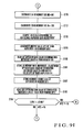
- the CPU 101 of the overlap detection apparatus 100 After executing the process in steps S171 to S175 ( Fig. 9F ) or the process in steps S222 to S226 ( Fig. 9K ), i.e., deciding the overlap detection monitor output and gain, the CPU 101 of the overlap detection apparatus 100 reads out the optimum driving frequency value Nsp of the ultrasonic transmission sensor from the memory M5 ( Fig. 9N : step S227) and outputs it to the VCO D/A converter 107 (step S228).
- the driving frequency f from the ultrasonic oscillation circuit 109 to the ultrasonic transmission sensor 110 is set to fNsp.
- the CPU 101 reads out the optimum gain value NGsp from the memory M15 (step S229) and outputs it to the D/A converter 115 for second amplifier gain adjustment (step S230).
- a gain GA NGsp is set in the second amplifier 113 as the overlap detection gain GAsp.
- the CPU 101 reads out the count value N ⁇ from the printing press rotation phase detection counter 116 (step S231), obtains the printing press rotation phase ⁇ based on the readout count value N ⁇ (step S232), reads out an overlap detection phase ⁇ sp from the memory M20 (step S233), and compares the printing press rotation phase ⁇ with the overlap detection phase ⁇ sp (step 5234).
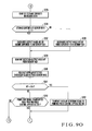
- step S234 The process in steps S231 to S234 is repeated, and if the printing press rotation phase ⁇ equals the overlap detection phase ⁇ sp (YES in step S234), the CPU reads out the storage contents from the memory M14 ( Fig. 9O : step S235). If the storage contents of the memory M14 represents "1" (plain paper) (YES in step S236), the CPU receives the output value AP2 from the second amplifier 113 via the A/D converter 119 and writes it in the memory M21 as the detection output value AP (step S237).
- the CPU receives the output value AP3 from the third amplifier 114 via the A/D converter 118 and writes it in the memory M21 as the detection output value AP (step S238).
- the CPU reads out the detection output value AP from the memory M21 (step S239) and also reads out an overlap detection threshold value Vth stored in the memory M16 (step S240). If the detection output value AP ⁇ Vth (YES in step S241), the CPU transmits an overlap detection signal to the printing press control apparatus 200 (step S243). If the detection output value AP ⁇ Vth does not hold (NO in step S241), the process returns from step S242 to step S231 ( Fig. 9N ) to repeat the same processing operation as described above.
- step S242 If a print stop signal from the printing press control apparatus 200 is confirmed in step S242, the process returns to step S119 ( Fig. 9C ) to wait for a print start signal from the printing press control apparatus 200.
- the CPU 201 of the printing press control apparatus 200 Upon receiving the overlap detection signal from the overlap detection apparatus 100 ( Fig. 10B : YES in step S306, YES in step S308), the CPU 201 of the printing press control apparatus 200 outputs a feed stop instruction to the feeding unit 208 (step S314) to stop paper feed from the feeding unit 208 to the printing press.
- the CPU also outputs a print stop instruction to the printing units 209 1 to 209 4 (step S315) to cause them to stop printing on paper sheets.
- the CPU also outputs a driving stop signal to the drive motor driver 210 (step S313) to stop the printing press.
- step S308 The overlap detection signal confirmation in step S308 is repeatedly executed after the output of the print start instruction to the printing units 209 1 to 209 4 (step S307). If the print stop switch 203 is turned on during this repetitive execution (YES in step S309), the CPU 201 of the printing press control apparatus 200 outputs a feed stop instruction to the feeding unit 208 (step S310), transmits a print stop signal to the overlap detection apparatus 100 (step S311), outputs a print stop instruction to the printing units 209 1 to 209 4 (step S312), and outputs a driving stop signal to the drive motor driver 210 (step S313).
- Fig. 20 shows functional blocks implemented by the CPU which operates in accordance with the overlap detection program.
- the CPU 101 implements at least an overlap detection monitor output & amplification factor decision unit 130 and an overlap detection unit 134.
- the overlap detection monitor output & amplification factor decision unit 130 comprises an amplification factor control unit 131, first overlap detection monitor output & amplification factor decision unit 132, and second overlap detection monitor output & amplification factor decision unit 133.
- the amplification factor control unit 131 controls the gain GA of the second amplifier 113.
- the amplification factor control unit 131 performs the processes in, e.g., steps S126 and S127, S137 to S146, S156 to S168, S177 and S178, S188 to S197, and S207 to S219.
- the amplification factor control unit 131 comprises a change width control unit 131A and a change direction control unit 131B.
- the change width control unit 131A repeatedly changes the gain GA of the second amplifier 113 while reducing the change width.
- the change width control unit 131A performs the processes in, e.g., steps S143 and S144, S156 to S161, S165 to S168, S194 and S195, S207 to S212, and S216 to S219.
- the change direction control unit 131B changes the gain GA of the second amplifier 113 in a direction different from that of the previous time. For example, when AP2 ⁇ Vs has changed to AP2 > Vs, the change direction control unit 131B changes the direction of the gain GA from an increasing direction to a decreasing direction.
- the change direction control unit 131B performs the processes in, e.g., steps S155 to S161, and S206 to S212.
- the first overlap detection monitor output & amplification factor decision unit 132 comprises a first equivalence determination unit 132A, first overlap detection monitor output decision unit 132B, and first overlap detection amplification factor decision unit 132C.
- the first equivalence determination unit 132A determines whether the output value AP2 of the second amplifier 113 is almost equal to the optimum gain value determination reference value Vs. If the absolute value of the difference between the output value AP2 of the second amplifier 113 and the optimum gain value determination reference value Vs is smaller than the optimum gain value determination threshold value (first threshold value) ⁇ Vsth, the first equivalence determination unit 132A determines that the output value AP2 of the second amplifier 113 is almost equal to the optimum gain value determination reference value Vs.
- the first equivalence determination unit 132A performs the processes in, e.g., steps S128 to S133, and S147 to S152.
- the first overlap detection monitor output decision unit 132B decides the output from the second amplifier 113 as the overlap detection monitor output.
- the first overlap detection monitor output decision unit 132B performs the process in, e.g., step S171.
- the first overlap detection amplification factor decision unit 132C decides, as the overlap detection gain GAsp, the gain GA of the second amplifier 113 when the output value AP2 of the second amplifier 113 has become almost equal to the optimum gain value determination reference value Vs.
- the first overlap detection amplification factor decision unit 132C performs the processes in, e.g., steps S172 and S173.
- the second overlap detection monitor output & amplification factor decision unit 133 comprises a second equivalence determination unit 133A, second overlap detection monitor output decision unit 133B, and second overlap detection amplification factor decision unit 133C.
- the second equivalence determination unit 133A determines whether the output value AP3 of the third amplifier 114 is almost equal to the optimum gain value determination reference value Vs. If the absolute value of the difference between the output value AP3 of the third amplifier 114 and the optimum gain value determination reference value Vs is smaller than the optimum gain value determination threshold value (second threshold value) ⁇ Vsth, the second equivalence determination unit 133A determines that the output value AP3 of the third amplifier 114 is almost equal to the optimum gain value determination reference value Vs.
- the second equivalence determination unit 133A performs the processes in, e.g., steps S179 to S184, and S198 to S203.
- the second overlap detection monitor output decision unit 133B decides the output from the third amplifier 114 as the overlap detection monitor output.
- the second overlap detection monitor output decision unit 133B performs the process in, e.g., step S222.
- the second overlap detection amplification factor decision unit 133C decides, as the overlap detection gain GAsp, the gain GA of the second amplifier 113 when the output value AP3 of the third amplifier 114 has become almost equal to the optimum gain value determination reference value Vs.
- the second overlap detection amplification factor decision unit 133C performs the processes in, e.g., steps S223 and S224.
- the overlap detection unit 134 Based on the output from the second or third amplifier 113 or 114 decided as the overlap detection monitor output by the first or second overlap detection monitor output decision unit 132B or 133B, the overlap detection unit 134 detects overlap of the fed paper sheets 4 which pass between the ultrasonic transmission sensor 110 and the ultrasonic reception sensor 111.
- the overlap detection unit 134 performs the processes in, e.g., steps S227 to S243.
- the amplification factor control unit 131 sets, in the second amplifier 113, the overlap detection gain GAsp decided by the first or second overlap detection amplification factor decision unit 132C or 133C.
- the amplification factor of the second amplifier is changed while sandwiching one sheet between the ultrasonic transmitter and the ultrasonic receiver.
- the output of the second amplifier is decided as the sheet overlap detection monitor output if the output value from the second amplifier is recognized to be almost equal to the first set value defined in advance. For example, if the amplification factor GA of the second amplifier is raised stepwise from GA 0 to GA 255 , and the output value AP2 from the second amplifier has become almost equal to the first set value (V2s) halfway (AP2 ⁇ V2s), the output from the second amplifier is decided as the overlap detection monitor output.
- the output from the third amplifier is decided as the overlap detection monitor output.
- the amplification factor GA of the second amplifier is raised stepwise from GA 0 to GA 255 , and AP2 ⁇ V2s does not hold, the amplification factor GA of the second amplifier is raised again stepwise from GA 0 to GA 255 . If the output value AP3 from the third amplifier becomes almost equal to the second set value (V3s) halfway (AP3 ⁇ V3s), the output from the third amplifier is decided as the overlap detection monitor output.
- the amplification factor of the second amplifier at that time is decided as the sheet overlap detection amplification factor.
- the amplification factor of the second amplifier at that time is decided as the overlap detection amplification factor.
- the amplification factor GA need not always be raised stepwise from GA 0 to GA 255 .
- the amplification factor GA is set to GA 128 first. If the output from the second amplifier at that time is smaller than the first set value, the amplification factor GA is raised to GA 192 .
- the amplification factor GA may be narrowed down in this way until the output value from the second amplifier almost equals the first set value.
- the output from the second amplifier and that from the third amplifier are stored while raising the amplification factor GA of the second amplifier stepwise from GA 0 to GA 255 . Then, the output value from the second amplifier and that from the third amplifier corresponding to each of the amplification factors GA 0 to GA 255 are observed. If the output value from the second amplifier is recognized to be almost equal to the first set value V2s, the output from the second amplifier is decided as the sheet overlap detection monitor output. If the output value from the second amplifier is not recognized to be almost equal to the first set value V2s, but the output value from the third amplifier is recognized to be almost equal to the second set value V3s, the output from the third amplifier is decided as the sheet overlap detection monitor output. This obviates changing the amplification factor GA of the second amplifier again and speeds up the processing.
- the first set value and the second set value may be different or the same.
- the first threshold value and the second threshold value may also be different or the same.
- the sheets as the overlap detection target are not limited to the fed paper sheets to the printing press.
Landscapes
- Physics & Mathematics (AREA)
- General Physics & Mathematics (AREA)
- Controlling Sheets Or Webs (AREA)
- Length Measuring Devices Characterised By Use Of Acoustic Means (AREA)
- Investigating Or Analyzing Materials By The Use Of Ultrasonic Waves (AREA)
Applications Claiming Priority (1)
| Application Number | Priority Date | Filing Date | Title |
|---|---|---|---|
| JP2007242919A JP2009073603A (ja) | 2007-09-19 | 2007-09-19 | シート状物の重複検出装置および重複検出方法 |
Publications (1)
| Publication Number | Publication Date |
|---|---|
| EP2039633A2 true EP2039633A2 (en) | 2009-03-25 |
Family
ID=40202066
Family Applications (1)
| Application Number | Title | Priority Date | Filing Date |
|---|---|---|---|
| EP08075764A Withdrawn EP2039633A2 (en) | 2007-09-19 | 2008-09-17 | Sheet overlap detection apparatus and sheet overlap detection method |
Country Status (4)
| Country | Link |
|---|---|
| US (1) | US20090072475A1 (OSRAM) |
| EP (1) | EP2039633A2 (OSRAM) |
| JP (1) | JP2009073603A (OSRAM) |
| CN (1) | CN101391713A (OSRAM) |
Cited By (1)
| Publication number | Priority date | Publication date | Assignee | Title |
|---|---|---|---|---|
| EP2769949A1 (de) * | 2013-02-21 | 2014-08-27 | Pepperl & Fuchs GmbH | Verfahren zum messtechnischen Unterscheiden von Materialbereichen eines blatt-, bahn- oder bogenartigen Materials sowie Vorrichtung hierzu |
Families Citing this family (7)
| Publication number | Priority date | Publication date | Assignee | Title |
|---|---|---|---|---|
| JP4640497B2 (ja) * | 2008-12-08 | 2011-03-02 | コニカミノルタビジネステクノロジーズ株式会社 | 画像形成装置 |
| US20120061901A1 (en) * | 2010-09-10 | 2012-03-15 | Kabushiki Kaisha Toshiba | Ultrasonic detecting device and sheet handling apparatus comprising ultrasonic detecting device |
| US8678384B2 (en) * | 2010-10-04 | 2014-03-25 | Kabushiki Kaisha Toshiba | Medium transport unit, sensor unit, and method of controlling reading of medium transport unit |
| JP5724469B2 (ja) * | 2011-03-08 | 2015-05-27 | 株式会社リコー | 重送検知装置、画像形成装置、及び重送検知プログラム |
| JP6337537B2 (ja) * | 2014-03-17 | 2018-06-06 | 株式会社リコー | 用紙搬送装置、画像形成装置及び重送判定方法 |
| CN106595550B (zh) * | 2015-10-17 | 2019-04-30 | 陈红胜 | 双张检测装置及其检测方法 |
| DE102017220316B3 (de) * | 2017-11-15 | 2018-10-11 | Heidelberger Druckmaschinen Ag | Positions-Messvorrichtung für Bedruckstoffbogen-Seitenkanten |
Citations (4)
| Publication number | Priority date | Publication date | Assignee | Title |
|---|---|---|---|---|
| JPS63290746A (ja) | 1987-05-25 | 1988-11-28 | Komori Printing Mach Co Ltd | 枚葉印刷機の用紙重複検出方法 |
| JPH02178145A (ja) | 1988-12-29 | 1990-07-11 | Komori Printing Mach Co Ltd | 給紙用紙の重複検出方法および装置 |
| JP2002338087A (ja) | 2001-05-11 | 2002-11-27 | Komori Corp | 段ボール供給装置の2枚送り検知装置 |
| JP2002338086A (ja) | 2001-05-11 | 2002-11-27 | Komori Corp | 段ボール供給装置の2枚送り検知装置 |
Family Cites Families (11)
| Publication number | Priority date | Publication date | Assignee | Title |
|---|---|---|---|---|
| JPH0974467A (ja) * | 1995-09-05 | 1997-03-18 | Canon Inc | 画像形成装置及びその記録媒体の識別方法 |
| US6540222B2 (en) * | 1999-12-28 | 2003-04-01 | Matsushita Electric Industrial Co., Ltd. | Sheet material feeding mechanism |
| JP2003160257A (ja) * | 2001-11-22 | 2003-06-03 | Omron Corp | 紙葉類重送検出装置および方法、並びにプログラム |
| JP2004256293A (ja) * | 2003-02-28 | 2004-09-16 | Hitachi Printing Solutions Ltd | 重送検出装置 |
| JP2004269241A (ja) * | 2003-03-12 | 2004-09-30 | Pfu Ltd | 給紙装置 |
| JP4260595B2 (ja) * | 2003-09-30 | 2009-04-30 | キヤノン電子株式会社 | 超音波重送検知装置 |
| JP4377666B2 (ja) * | 2003-12-04 | 2009-12-02 | ニスカ株式会社 | シート供給装置並びに画像読取装置 |
| JP4381133B2 (ja) * | 2003-12-24 | 2009-12-09 | ニスカ株式会社 | シート供給装置及びこれを用いた画像読取装置 |
| JP4451724B2 (ja) * | 2004-06-08 | 2010-04-14 | ニスカ株式会社 | 給紙装置及び重送検知異常判別方法 |
| JP4691676B2 (ja) * | 2005-05-09 | 2011-06-01 | コニカミノルタビジネステクノロジーズ株式会社 | シートの重送検知方法及び給紙装置 |
| JP4775046B2 (ja) * | 2006-03-15 | 2011-09-21 | コニカミノルタビジネステクノロジーズ株式会社 | 用紙搬送装置及び画像形成装置 |
-
2007
- 2007-09-19 JP JP2007242919A patent/JP2009073603A/ja not_active Ceased
-
2008
- 2008-09-17 US US12/284,005 patent/US20090072475A1/en not_active Abandoned
- 2008-09-17 EP EP08075764A patent/EP2039633A2/en not_active Withdrawn
- 2008-09-18 CN CNA200810215215XA patent/CN101391713A/zh active Pending
Patent Citations (4)
| Publication number | Priority date | Publication date | Assignee | Title |
|---|---|---|---|---|
| JPS63290746A (ja) | 1987-05-25 | 1988-11-28 | Komori Printing Mach Co Ltd | 枚葉印刷機の用紙重複検出方法 |
| JPH02178145A (ja) | 1988-12-29 | 1990-07-11 | Komori Printing Mach Co Ltd | 給紙用紙の重複検出方法および装置 |
| JP2002338087A (ja) | 2001-05-11 | 2002-11-27 | Komori Corp | 段ボール供給装置の2枚送り検知装置 |
| JP2002338086A (ja) | 2001-05-11 | 2002-11-27 | Komori Corp | 段ボール供給装置の2枚送り検知装置 |
Cited By (2)
| Publication number | Priority date | Publication date | Assignee | Title |
|---|---|---|---|---|
| EP2769949A1 (de) * | 2013-02-21 | 2014-08-27 | Pepperl & Fuchs GmbH | Verfahren zum messtechnischen Unterscheiden von Materialbereichen eines blatt-, bahn- oder bogenartigen Materials sowie Vorrichtung hierzu |
| US9465021B2 (en) | 2013-02-21 | 2016-10-11 | Pepperl + Fuchs Gmbh | Method for metrologically differentiating material regions of a page-like, web-like or sheet-like material and device therefor |
Also Published As
| Publication number | Publication date |
|---|---|
| US20090072475A1 (en) | 2009-03-19 |
| JP2009073603A (ja) | 2009-04-09 |
| CN101391713A (zh) | 2009-03-25 |
Similar Documents
| Publication | Publication Date | Title |
|---|---|---|
| EP2039633A2 (en) | Sheet overlap detection apparatus and sheet overlap detection method | |
| JP2003176063A (ja) | 紙葉類重送検出装置および方法、並びにプログラム | |
| US6698753B2 (en) | Device for and method of detecting an overlap in paper being transported | |
| EP1429472A3 (en) | Wireless communication apparatus and transmission power control method thereof | |
| CN111813352A (zh) | 一种打印缺纸检测方法、装置、设备及存储介质 | |
| US20050275159A1 (en) | Sheet feeding apparatus with ultrasonic sensor for detecting multiple feed of papers | |
| JP2017216494A (ja) | 画像読取装置、画像補正方法 | |
| EP0404287B1 (en) | Sheet overlapping detecting method | |
| JP2009073604A (ja) | シート状物の重複検出装置および重複検出方法 | |
| JP2009234793A (ja) | シート状部材の重送検知装置 | |
| EP1872947B1 (en) | Ink fountain key position adjusting method and apparatus for printing press | |
| JP2009073605A (ja) | シート状物の重複検出装置および重複検出方法 | |
| JP2017149504A (ja) | 媒体搬送装置、画像読取装置、重送判定方法及び重送判定プログラム | |
| JP2000025988A (ja) | 超音波を利用したシート材の重送検知方法 | |
| JP5757211B2 (ja) | 処理装置 | |
| JP2000025986A (ja) | 超音波を利用したシート材の重送検知方法 | |
| JP4449607B2 (ja) | 後処理装置及び画像形成システム | |
| US6684767B1 (en) | Sheet carrier apparatus | |
| JP2019123603A (ja) | シート搬送装置、シート搬送装置の制御方法およびプログラム | |
| JP2012184093A (ja) | 用紙搬送装置、画像形成装置及び用紙搬送装置の制御方法 | |
| JP2002048529A (ja) | 送信器と受信器との間の位相シフトを補正する方法及び装置 | |
| JP2617125B2 (ja) | 給紙用紙の重複検出方法および装置 | |
| US20180334343A1 (en) | Transporting apparatus | |
| JPH1135196A (ja) | センサ自動調整装置 | |
| EP1308613B1 (en) | Throttle valve opened amount calculator |
Legal Events
| Date | Code | Title | Description |
|---|---|---|---|
| PUAI | Public reference made under article 153(3) epc to a published international application that has entered the european phase |
Free format text: ORIGINAL CODE: 0009012 |
|
| 17P | Request for examination filed |
Effective date: 20080917 |
|
| AK | Designated contracting states |
Kind code of ref document: A2 Designated state(s): AT BE BG CH CY CZ DE DK EE ES FI FR GB GR HR HU IE IS IT LI LT LU LV MC MT NL NO PL PT RO SE SI SK TR |
|
| AX | Request for extension of the european patent |
Extension state: AL BA MK RS |
|
| STAA | Information on the status of an ep patent application or granted ep patent |
Free format text: STATUS: THE APPLICATION IS DEEMED TO BE WITHDRAWN |
|
| 18D | Application deemed to be withdrawn |
Effective date: 20110331 |