EP2038625B1 - Dispositif de mesure de température - Google Patents
Dispositif de mesure de température Download PDFInfo
- Publication number
- EP2038625B1 EP2038625B1 EP07764375A EP07764375A EP2038625B1 EP 2038625 B1 EP2038625 B1 EP 2038625B1 EP 07764375 A EP07764375 A EP 07764375A EP 07764375 A EP07764375 A EP 07764375A EP 2038625 B1 EP2038625 B1 EP 2038625B1
- Authority
- EP
- European Patent Office
- Prior art keywords
- sensing head
- temperature measuring
- pipe piece
- measuring apparatus
- pipe section
- Prior art date
- Legal status (The legal status is an assumption and is not a legal conclusion. Google has not performed a legal analysis and makes no representation as to the accuracy of the status listed.)
- Active
Links
Images


Classifications
-
- G—PHYSICS
- G01—MEASURING; TESTING
- G01K—MEASURING TEMPERATURE; MEASURING QUANTITY OF HEAT; THERMALLY-SENSITIVE ELEMENTS NOT OTHERWISE PROVIDED FOR
- G01K13/00—Thermometers specially adapted for specific purposes
- G01K13/02—Thermometers specially adapted for specific purposes for measuring temperature of moving fluids or granular materials capable of flow
- G01K13/024—Thermometers specially adapted for specific purposes for measuring temperature of moving fluids or granular materials capable of flow of moving gases
-
- G—PHYSICS
- G01—MEASURING; TESTING
- G01K—MEASURING TEMPERATURE; MEASURING QUANTITY OF HEAT; THERMALLY-SENSITIVE ELEMENTS NOT OTHERWISE PROVIDED FOR
- G01K13/00—Thermometers specially adapted for specific purposes
- G01K13/02—Thermometers specially adapted for specific purposes for measuring temperature of moving fluids or granular materials capable of flow
- G01K13/026—Thermometers specially adapted for specific purposes for measuring temperature of moving fluids or granular materials capable of flow of moving liquids
-
- G—PHYSICS
- G01—MEASURING; TESTING
- G01K—MEASURING TEMPERATURE; MEASURING QUANTITY OF HEAT; THERMALLY-SENSITIVE ELEMENTS NOT OTHERWISE PROVIDED FOR
- G01K7/00—Measuring temperature based on the use of electric or magnetic elements directly sensitive to heat ; Power supply therefor, e.g. using thermoelectric elements
- G01K7/16—Measuring temperature based on the use of electric or magnetic elements directly sensitive to heat ; Power supply therefor, e.g. using thermoelectric elements using resistive elements
- G01K7/22—Measuring temperature based on the use of electric or magnetic elements directly sensitive to heat ; Power supply therefor, e.g. using thermoelectric elements using resistive elements the element being a non-linear resistance, e.g. thermistor
Definitions
- Temperature sensors are z. B. from the document DE 10340636 B3 known.
- the publication JP 2002 005757 A discloses a temperature measuring device in which a sensor element is embedded in a recess of a pipe to detect the temperature of a medium flowing through the pipe.
- a media-carrying device with temperature measurement in the medium in which a sensor assembly is arranged on a lateral outlet of a pipeline.
- the sensor assembly includes a sensor housing with an electrical temperature sensor and two contact pins protruding from the sensor housing.
- the publication JP 2006 058231 A describes a device for measuring the temperature of liquids or gases in a container in which a protective tube, in which a temperature sensor is arranged, is inserted into a mounting hole of the container.
- An object to be solved is to specify a measuring device which is suitable for detecting the temperature of a medium flowing in a line system.
- the pipe section is to carry out provided a medium whose temperature is to be detected by means of the sensing head.
- the sensing head is preferably in the wall, d. H. embedded in the shell of the pipe section.
- the medium to be subjected to a temperature measurement is preferably a flowing through the tube medium such.
- a flowing through the tube medium such.
- the flowing liquid can, for. As water, oil, fuel, alkali, etc. include.
- the inside of the pipe section has no interfaces to be sealed in the region of the sensor head, ie interfaces between two adjoining parts.
- An interface-free integration of the sensing head in a part of a line system allows a non-invasive temperature measurement of a medium flowing through the line system. Such a measurement is advantageous because it - im Contrary to an invasive temperature measurement, in which a feeler head is passed through the wall of the pipe system - no leaks can occur.
- the pipe section preferably has an inwardly facing emphasis in which at least a part of the sensing head is enclosed.
- the sensing head can also be enclosed in a region of the wall of the pipe section which has no inwardly projecting highlights.
- the pipe section may have front side arranged locking devices, which in particular allow the application of hoses of a pipe system.
- the pipe section of the specified measuring device can be arranged between two hoses through which the cooling water flows to cool a motor.
- the pipe section may also be formed of a material having elastic properties. Such a trained piece of pipe can be used as a seal between two pipes.
- the pipe section may have a larger diameter at the end than in the adjacent areas, a chamfer and / or a ribbing.
- the pipe section is preferably monolithically connected to a plug device, in which electrical supply lines are integrated, which are conductively connected to the sensing head. Due to the monolithic connection of the pipe section and the connector device can be dispensed with the mounting of the connector device on the pipe section by means of holding devices.
- At least one thermally conductive body is preferably embedded, which contacts the feeler head.
- the thermal conductivity of the heat-conducting body exceeds that of the pipe section.
- the thermally conductive body is preferably formed flat to receive and average the temperature of the medium flowing through the pipe at various points of the pipe section.
- the thermally conductive body is preferably embedded in the pipe section and disposed in the vicinity of the inner surface of the pipe section. It is advantageous if the thermally conductive body follows at least a portion of the pipe circumference and z. B. as a ring or partial ring is formed.
- the thermally conductive body may also extend in the longitudinal direction of the pipe section.
- the thermally conductive body preferably comprises metal. But it can also be used as an injection molded part z. B. be formed of a plastic which is filled with metal particles. Other materials with a high thermal conductivity are suitable for this purpose.
- the temperature measuring device comprises a sensing head 1, which preferably comprises an NTC sensor element.
- NTC stands for Negative Temperature Coefficient.
- the temperature measuring device further comprises a tube piece 2, in which the sensing head 1 is enclosed.
- the sensing head 1 is preferably cast in the body of the pipe section so that there are no interfaces. In particular, the inside of the pipe section has no sealed interfaces between the pipe section and the sensing element.
- the sensing head 1 is soldered to electrical leads 11, which are conductively connected to the electrical terminals 31 of the temperature measuring device.
- the leads 11 and the terminals 31 are integrated in a plug connection 3, which is formed prior to molding of the pipe section.
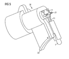
- the plug connection 3 comprises a housing 30, which is preferably available as a molded part. In this case, the leads 11 are performed. In the housing 30, at least a part of the terminals 31 are also arranged. Also the feeler head 1 may be arranged in a variant partially in the housing 30.
- the not yet integrated into the pipe section 2 housing 30 is in the Figures 5 and 6 shown.
- the leads 11 are free.
- the in Fig. 2 visible part 39 of the housing is produced together with the pipe section 2, ie in the same process step, wherein the leads 11 are embedded in a casting material.
- the part 39 of the housing 30 and the pipe piece 2 are formed in one piece.
- the housing 30 of the plug connection 3 preferably comprises a base 33, which is monolithically connected to the pipe section 2.
- the base 33 has a curvature, which preferably follows a circular arc, which results from the course of the pipe section 2.
- the pipe section 2 is preferably produced as a molded part in a compression or injection molding process, wherein the base 33 of the plug connection 3 is preferably at least partially pressed by the molding compound.
- the plug connection 3 can be connected to a further plug connection formed complementary to it, which is conductively connected to a circuit for evaluating the measurement signals detected by the sensor head 1.
- the longitudinal axis of the plug connection 3 is arranged transversely to the longitudinal axis of the pipe section 2 in the variants shown. But it can also be aligned parallel or obliquely to the longitudinal axis of the pipe section 2.
- the sensing head 1 may, for example, as in FIG. 3 be included in a highlight 21 of the pipe section 2, which protrudes into the inner opening of the pipe section, but is still a part of the pipe section.
- At least one good heat-conducting body 10 may preferably be embedded in metal, which touches the sensing head 1.
- a good heat-conducting body means a body whose thermal conductivity is greater than that of the environment (i.e.
- the thermally conductive body 10 is preferably completely embedded in the wall of the pipe section.
- the thermally conductive body 10 is flat, formed in this variant in the form of a partial ring.
- the thermally conductive body may also have the shape of a pot, in which preferably a part of the sensing head 1 is arranged.
- the pipe section 2 can be connected on both sides to other pipes and then becomes a component of a conduit system for carrying out a - preferably the conduit system flowing through - medium whose temperature is to be measured.
- the medium may comprise a gas or a liquid.
- the pipe section can be used as a nozzle, on the front sides hoses are mounted. End-side regions 22 of the pipe section 2 preferably have latching devices.
- the pipe section 2, which comprises the sensing head 1, has a thickening in the area 23, since in this area preferably a base of the plug connection 3 is cast.
- the pipe section 2 may have a collar 24, are arranged in the openings 241 for receiving fasteners.
- the pipe section can be attached to a carrier.
Abstract
Claims (10)
- Dispositif de mesure de température présentant :une tête sensible (1) sur laquelle sont brasés des conducteurs électriques et une pièce tubulaire dans laquelle la tête sensible (1) est incorporée,la pièce tubulaire (2) étant prévue pour le passage d'un fluide dont la température peut être détectée au moyen de la tête sensible (1),
caractérisé en ce queau moins un corps (10) conducteur de chaleur, en contact avec la tête sensible (1), est incorporé dans la pièce tubulaire (2),la conductivité thermique du corps (10) conducteur de chaleur étant supérieure à celle de la pièce tubulaire (2). - Dispositif de mesure de température selon la revendication 1, dans lequel la pièce tubulaire (2) présente une saillie (21) orientée vers l'intérieur et dans laquelle au moins une partie de la tête sensible (1) est enfermée.
- Dispositif de mesure de température selon les revendications 1 ou 2, dans lequel le côté intérieur de la pièce tubulaire (2) ne présente pas d'interface dans la zone de la tête sensible (1).
- Dispositif de mesure de température selon l'une des revendications 1 à 3, dans lequel la pièce tubulaire (2) présente sur son côté frontal des dispositifs d'encliquetage.
- Dispositif de mesure de température selon l'une des revendications 1 à 4, dans lequel la pièce tubulaire (2) est reliée monolithiquement à un dispositif d'enfichage (3) dans lequel sont intégrés des conducteurs électriques (11) reliés électriquement à la tête sensible (1).
- Dispositif de mesure de température selon l'une des revendications 1 à 5, dans lequel la pièce tubulaire (2) présente dans une partie périphérique (23) qui inclut la tête sensible (1) un diamètre plus grand que dans les parties adjacentes.
- Dispositif de mesure de température selon l'une des revendications 1 à 6, dans lequel la pièce tubulaire (2) comporte comme matériau de base un matériau à propriétés élastiques.
- Dispositif de mesure de température selon l'une des revendications 1 à 6, dans lequel la pièce tubulaire (2) est une pièce moulée par injection.
- Dispositif de mesure de température selon l'une des revendications 1 à 8, dans lequel la tête sensible (1) comprend un élément NTC.
- Dispositif de mesure de température selon la revendication 1, dans lequel le corps conducteur de chaleur a une configuration aplatie.
Priority Applications (3)
| Application Number | Priority Date | Filing Date | Title |
|---|---|---|---|
| EP11159822.3A EP2339309B1 (fr) | 2006-07-06 | 2007-06-15 | Dispositif de mesure de température |
| EP11159821A EP2339308A1 (fr) | 2006-07-06 | 2007-06-15 | Dispositif de mesure de température |
| EP11159819.9A EP2339307B1 (fr) | 2006-07-06 | 2007-06-15 | Dispositif de mesure de température |
Applications Claiming Priority (2)
| Application Number | Priority Date | Filing Date | Title |
|---|---|---|---|
| DE102006031343A DE102006031343A1 (de) | 2006-07-06 | 2006-07-06 | Temperaturmessvorrichtung |
| PCT/DE2007/001059 WO2008003280A1 (fr) | 2006-07-06 | 2007-06-15 | Dispositif de mesure de température |
Related Child Applications (8)
| Application Number | Title | Priority Date | Filing Date |
|---|---|---|---|
| EP11159822.3A Division-Into EP2339309B1 (fr) | 2006-07-06 | 2007-06-15 | Dispositif de mesure de température |
| EP11159822.3A Division EP2339309B1 (fr) | 2006-07-06 | 2007-06-15 | Dispositif de mesure de température |
| EP11159819.9A Division-Into EP2339307B1 (fr) | 2006-07-06 | 2007-06-15 | Dispositif de mesure de température |
| EP11159819.9A Division EP2339307B1 (fr) | 2006-07-06 | 2007-06-15 | Dispositif de mesure de température |
| EP11159821A Division-Into EP2339308A1 (fr) | 2006-07-06 | 2007-06-15 | Dispositif de mesure de température |
| EP11159819.9 Division-Into | 2011-03-25 | ||
| EP11159821.5 Division-Into | 2011-03-25 | ||
| EP11159822.3 Division-Into | 2011-03-25 |
Publications (3)
| Publication Number | Publication Date |
|---|---|
| EP2038625A1 EP2038625A1 (fr) | 2009-03-25 |
| EP2038625B1 true EP2038625B1 (fr) | 2011-08-10 |
| EP2038625B2 EP2038625B2 (fr) | 2015-05-20 |
Family
ID=38573070
Family Applications (4)
| Application Number | Title | Priority Date | Filing Date |
|---|---|---|---|
| EP07764375.7A Active EP2038625B2 (fr) | 2006-07-06 | 2007-06-15 | Dispositif de mesure de température |
| EP11159819.9A Active EP2339307B1 (fr) | 2006-07-06 | 2007-06-15 | Dispositif de mesure de température |
| EP11159821A Withdrawn EP2339308A1 (fr) | 2006-07-06 | 2007-06-15 | Dispositif de mesure de température |
| EP11159822.3A Active EP2339309B1 (fr) | 2006-07-06 | 2007-06-15 | Dispositif de mesure de température |
Family Applications After (3)
| Application Number | Title | Priority Date | Filing Date |
|---|---|---|---|
| EP11159819.9A Active EP2339307B1 (fr) | 2006-07-06 | 2007-06-15 | Dispositif de mesure de température |
| EP11159821A Withdrawn EP2339308A1 (fr) | 2006-07-06 | 2007-06-15 | Dispositif de mesure de température |
| EP11159822.3A Active EP2339309B1 (fr) | 2006-07-06 | 2007-06-15 | Dispositif de mesure de température |
Country Status (8)
| Country | Link |
|---|---|
| US (1) | US8177425B2 (fr) |
| EP (4) | EP2038625B2 (fr) |
| JP (1) | JP2009543028A (fr) |
| KR (2) | KR101570646B1 (fr) |
| CN (2) | CN102692285B (fr) |
| DE (1) | DE102006031343A1 (fr) |
| ES (1) | ES2368957T5 (fr) |
| WO (1) | WO2008003280A1 (fr) |
Cited By (7)
| Publication number | Priority date | Publication date | Assignee | Title |
|---|---|---|---|---|
| WO2021047880A1 (fr) | 2019-09-12 | 2021-03-18 | Endress+Hauser Wetzer Gmbh+Co. Kg | Thermomètre non invasif |
| WO2021047881A1 (fr) | 2019-09-12 | 2021-03-18 | Endress+Hauser Wetzer Gmbh+Co. Kg | Thermomètre non invasif |
| WO2021047884A1 (fr) | 2019-09-12 | 2021-03-18 | Endress+Hauser Wetzer Gmbh+Co. Kg | Thermomètre non invasif |
| WO2021047882A1 (fr) | 2019-09-12 | 2021-03-18 | Endress+Hauser Wetzer Gmbh+Co. Kg | Thermomètre non invasif |
| WO2021083871A1 (fr) | 2019-10-31 | 2021-05-06 | Endress+Hauser Wetzer Gmbh+Co. Kg | Thermomètre non invasif |
| WO2022218649A1 (fr) | 2021-04-14 | 2022-10-20 | Endress+Hauser Wetzer Gmbh+Co. Kg | Élément de couplage pour un dispositif servant à déterminer et/ou à surveiller une grandeur de processus |
| DE102022127611A1 (de) | 2022-10-19 | 2024-04-25 | Endress+Hauser Wetzer Gmbh+Co. Kg | Messaufnehmer für eine thermische Messgröße und Messstelle mit einem solchen Messaufnehmer |
Families Citing this family (10)
| Publication number | Priority date | Publication date | Assignee | Title |
|---|---|---|---|---|
| DE102008029192A1 (de) | 2008-03-13 | 2009-09-24 | Epcos Ag | Fühler zum Erfassen einer physikalischen Größe und Verfahren zur Herstellung des Fühlers |
| EP2417432B1 (fr) * | 2009-04-09 | 2020-02-12 | Schlumberger Technology Corporation | Procédé et système pour la détection d'une invasion de fluide dans un espace annulaire d'un tuyau flexible |
| IT1396707B1 (it) * | 2009-07-06 | 2012-12-14 | Ufi Filters Spa | Gruppo filtrante perfezionato per motori endotermici a gasolio con dispositivo riscaldatore |
| DE102009060363A1 (de) | 2009-12-24 | 2011-06-30 | Volkswagen AG, 38440 | Verbindungseinheit |
| DE102012006144B3 (de) * | 2012-03-28 | 2013-08-14 | Inor Process Ab | Temperaturmessvorrichtung |
| US9976409B2 (en) * | 2013-10-08 | 2018-05-22 | Halliburton Energy Services, Inc. | Assembly for measuring temperature of materials flowing through tubing in a well system |
| CN106233109B (zh) * | 2014-04-23 | 2019-03-12 | 西门子能源有限公司 | 确定用于燃气涡轮发动机的声学收发器的波导温度的方法 |
| US20160003685A1 (en) * | 2014-07-03 | 2016-01-07 | Vareck Walla | Mounting Apparatus for Temperature Sensor |
| DE202015103863U1 (de) * | 2015-07-23 | 2015-08-20 | Abb Technology Ag | Oberflächentemperaturfühler |
| CN105628225B (zh) * | 2016-03-02 | 2018-12-25 | 平高集团有限公司 | 一种测温装置及使用该测温装置的gil |
Family Cites Families (21)
| Publication number | Priority date | Publication date | Assignee | Title |
|---|---|---|---|---|
| US1758532A (en) * | 1928-04-20 | 1930-05-13 | Edward D Phinney | Temperature-measuring device |
| US3167733A (en) † | 1964-02-28 | 1965-01-26 | Universal Oil Prod Co | Resistance temperature sensing element |
| US3881181A (en) * | 1973-02-22 | 1975-04-29 | Rca Corp | Semiconductor temperature sensor |
| US3848466A (en) * | 1974-01-30 | 1974-11-19 | Atomic Energy Commission | Magnetic temperature sensor |
| US3897272A (en) * | 1974-07-29 | 1975-07-29 | Honeywell Inc | Sturdy sensing apparatus for measuring the temperature of a heated rubber material during its curing process and method for making same |
| AT350300B (de) * | 1975-11-12 | 1979-05-25 | Setron Erzeugung Elektronische | Einrichtung zur temperaturmessung stroemender fluessigkeiten |
| JPS59184840U (ja) † | 1983-05-26 | 1984-12-08 | 株式会社豊田中央研究所 | 体外循環体液用温度センサ− |
| JPS63253223A (ja) * | 1987-04-09 | 1988-10-20 | Terumo Corp | 温度測定器 |
| FR2737007B1 (fr) * | 1995-07-18 | 1997-09-19 | Elf Antar France | Dispositif de mesure de la temperature d'une paroi chaude |
| DE19608675C2 (de) * | 1996-03-06 | 1999-07-29 | Delphi Automotive Systems Gmbh | Temperaturmeßvorrichtung mit einer medienführenden Rohrleitung |
| KR200210049Y1 (ko) * | 1998-05-29 | 2001-03-02 | 배길호 | 교환가능한 온도측정장치의 단열구조 |
| DE29914553U1 (de) * | 1999-08-19 | 1999-12-02 | Temperaturmestechnik Geraberg | Vorrichtung zur Bestimmung der Temperatur in Rohrleitungen |
| JP2002005757A (ja) * | 2000-06-27 | 2002-01-09 | Denso Corp | 温度センサ装置 |
| DE10110343A1 (de) * | 2001-03-03 | 2002-09-12 | Bosch Gmbh Robert | Steckvorrichtung |
| US7249885B2 (en) * | 2002-10-16 | 2007-07-31 | Clyde Bergemann Gmbh | Heat flux measuring device for pressure pipes, method for producing a measuring device, method for monitoring an operating state of a heat exchanger, heat exchanger and method for measuring a heat flux |
| DE10314705B3 (de) * | 2003-03-31 | 2004-07-01 | Heraeus Sensor Technology Gmbh | Vorrichtung zur Bestimmung der Temperatur eines strömenden Mediums in einer Rohr- oder Schlauchleitung |
| JP2004361217A (ja) * | 2003-06-04 | 2004-12-24 | Mitsubishi Electric Corp | 温度検知装置 |
| DE10340636B3 (de) | 2003-09-03 | 2005-01-13 | Epcos Ag | Verfahren zur Herstellung eines feuchtedichten Fühlers |
| DE10357222A1 (de) * | 2003-12-08 | 2005-06-30 | Basf Ag | Anschlussstutzen für Messgeräte und mit einem solchen Anschlussstutzen versehene Messsonde |
| JP2006058231A (ja) * | 2004-08-23 | 2006-03-02 | Nesstech Inc | 温度計 |
| CN2757103Y (zh) * | 2004-11-25 | 2006-02-08 | 李春 | 管卡安装型温度传感器 |
-
2006
- 2006-07-06 DE DE102006031343A patent/DE102006031343A1/de not_active Ceased
-
2007
- 2007-06-15 KR KR1020157003720A patent/KR101570646B1/ko active IP Right Grant
- 2007-06-15 WO PCT/DE2007/001059 patent/WO2008003280A1/fr active Application Filing
- 2007-06-15 EP EP07764375.7A patent/EP2038625B2/fr active Active
- 2007-06-15 CN CN201210181200.2A patent/CN102692285B/zh not_active Expired - Fee Related
- 2007-06-15 CN CNA2007800255757A patent/CN101484786A/zh active Pending
- 2007-06-15 ES ES07764375.7T patent/ES2368957T5/es active Active
- 2007-06-15 EP EP11159819.9A patent/EP2339307B1/fr active Active
- 2007-06-15 KR KR1020097002388A patent/KR101633124B1/ko active IP Right Grant
- 2007-06-15 EP EP11159821A patent/EP2339308A1/fr not_active Withdrawn
- 2007-06-15 EP EP11159822.3A patent/EP2339309B1/fr active Active
- 2007-06-15 JP JP2009516881A patent/JP2009543028A/ja active Pending
-
2009
- 2009-01-05 US US12/348,713 patent/US8177425B2/en active Active
Cited By (8)
| Publication number | Priority date | Publication date | Assignee | Title |
|---|---|---|---|---|
| WO2021047880A1 (fr) | 2019-09-12 | 2021-03-18 | Endress+Hauser Wetzer Gmbh+Co. Kg | Thermomètre non invasif |
| WO2021047881A1 (fr) | 2019-09-12 | 2021-03-18 | Endress+Hauser Wetzer Gmbh+Co. Kg | Thermomètre non invasif |
| WO2021047884A1 (fr) | 2019-09-12 | 2021-03-18 | Endress+Hauser Wetzer Gmbh+Co. Kg | Thermomètre non invasif |
| WO2021047882A1 (fr) | 2019-09-12 | 2021-03-18 | Endress+Hauser Wetzer Gmbh+Co. Kg | Thermomètre non invasif |
| WO2021083871A1 (fr) | 2019-10-31 | 2021-05-06 | Endress+Hauser Wetzer Gmbh+Co. Kg | Thermomètre non invasif |
| WO2022218649A1 (fr) | 2021-04-14 | 2022-10-20 | Endress+Hauser Wetzer Gmbh+Co. Kg | Élément de couplage pour un dispositif servant à déterminer et/ou à surveiller une grandeur de processus |
| DE102021109410A1 (de) | 2021-04-14 | 2022-10-20 | Endress + Hauser Wetzer Gmbh + Co. Kg | Nicht invasives Thermometer |
| DE102022127611A1 (de) | 2022-10-19 | 2024-04-25 | Endress+Hauser Wetzer Gmbh+Co. Kg | Messaufnehmer für eine thermische Messgröße und Messstelle mit einem solchen Messaufnehmer |
Also Published As
| Publication number | Publication date |
|---|---|
| ES2368957T5 (es) | 2015-06-18 |
| EP2038625B2 (fr) | 2015-05-20 |
| WO2008003280A1 (fr) | 2008-01-10 |
| KR20090045226A (ko) | 2009-05-07 |
| EP2339307A1 (fr) | 2011-06-29 |
| CN101484786A (zh) | 2009-07-15 |
| KR20150028360A (ko) | 2015-03-13 |
| EP2038625A1 (fr) | 2009-03-25 |
| EP2339307B1 (fr) | 2016-12-28 |
| KR101570646B1 (ko) | 2015-11-20 |
| CN102692285A (zh) | 2012-09-26 |
| ES2368957T3 (es) | 2011-11-24 |
| US20090193887A1 (en) | 2009-08-06 |
| US8177425B2 (en) | 2012-05-15 |
| DE102006031343A1 (de) | 2008-01-10 |
| EP2339309B1 (fr) | 2019-05-08 |
| EP2339308A1 (fr) | 2011-06-29 |
| CN102692285B (zh) | 2015-08-12 |
| KR101633124B1 (ko) | 2016-06-23 |
| EP2339309A1 (fr) | 2011-06-29 |
| JP2009543028A (ja) | 2009-12-03 |
Similar Documents
| Publication | Publication Date | Title |
|---|---|---|
| EP2038625B1 (fr) | Dispositif de mesure de température | |
| DE102004013582B4 (de) | Verfahren zur Befestigung eines Temperatursensors in einer Drucksensorvorrichtung | |
| DE19534887B4 (de) | Temperaturfühler | |
| EP2047223B1 (fr) | Dispositif de détection de pression | |
| DE19522067A1 (de) | Kraftstoffeinspritz-Versorgungssammelleitung | |
| DE19517676B4 (de) | Drucksensor für eine Brennkraftmaschine mit einem Ansaugrohr | |
| EP2831555A1 (fr) | Capteur destiné à la détection d'une pression et d'une température d'un milieu fluide | |
| DE102007056544A1 (de) | Sensoranordnung zur Bestimmung eines Tankfüllstands und Verfahren zur Herstellung hierzu | |
| WO1999053276A1 (fr) | Dispositif pour mesurer la masse d'un fluide en ecoulement | |
| EP3134715A1 (fr) | Dispositif de raccordement, procédé de fabrication d'un dispositif de raccordement, dispositif de mesure et procédé de fabrication d'un dispositif de mesure | |
| DE10117731C1 (de) | Befestigungselement zur Fixierung von Betriebsparamenter sensierenden Anbaukomponenten an Anschlussstellen im Leitungssystem sowie dessen Verwendung | |
| DE102009055057A1 (de) | Sensor | |
| DE102006003602B4 (de) | Oberflächensensor, Sensoranordnung und Klimaanlage | |
| DE102008030363A1 (de) | Sensoranordnung | |
| DE202013007490U1 (de) | Temperatursensor für ein Fluid | |
| DE102007025626A1 (de) | Gassensor | |
| WO2019063175A1 (fr) | Bague d'étanchéité comprenant un capteur, liaison fluidique, circuit de refroidissement et procédé de fabrication d'un joint d'étanchéité | |
| DE20100277U1 (de) | Messvorrichtung eines elektronischen Thermometers | |
| EP2072967A1 (fr) | Capteur électronique et procédé de fabrication d'un capteur | |
| WO2002040928A1 (fr) | Echangeur thermique pour systeme de chauffage supplementaire de vehicule | |
| DE102021210954A1 (de) | Medienführungssystem mit einer Medienführung und mit einem Temperatursensor | |
| AT504958A2 (de) | Piezoelektrische sensoreinrichtung | |
| DE102021127433A1 (de) | Leitungsverbindungsvorrichtung | |
| DE102016219992A1 (de) | Sensor zur Erfassung wenigstens der Temperatur eines strömenden Mediums | |
| DE2313549A1 (de) | Massetemperatur-messwertgeber fuer plastverarbeitungsmaschinen |
Legal Events
| Date | Code | Title | Description |
|---|---|---|---|
| PUAI | Public reference made under article 153(3) epc to a published international application that has entered the european phase |
Free format text: ORIGINAL CODE: 0009012 |
|
| 17P | Request for examination filed |
Effective date: 20090120 |
|
| AK | Designated contracting states |
Kind code of ref document: A1 Designated state(s): AT BE BG CH CY CZ DE DK EE ES FI FR GB GR HU IE IS IT LI LT LU LV MC MT NL PL PT RO SE SI SK TR |
|
| AX | Request for extension of the european patent |
Extension state: AL BA HR MK RS |
|
| RIN1 | Information on inventor provided before grant (corrected) |
Inventor name: BALZER, PETER Inventor name: GRUNDMANN, WOLFGANG Inventor name: OSTRICK, BERNHARD |
|
| 17Q | First examination report despatched |
Effective date: 20090417 |
|
| DAX | Request for extension of the european patent (deleted) | ||
| RBV | Designated contracting states (corrected) |
Designated state(s): DE ES FR GB IT |
|
| GRAP | Despatch of communication of intention to grant a patent |
Free format text: ORIGINAL CODE: EPIDOSNIGR1 |
|
| GRAS | Grant fee paid |
Free format text: ORIGINAL CODE: EPIDOSNIGR3 |
|
| GRAA | (expected) grant |
Free format text: ORIGINAL CODE: 0009210 |
|
| RIN1 | Information on inventor provided before grant (corrected) |
Inventor name: BALZER, PETER Inventor name: OSTRICK, BERNHARD Inventor name: GRUNDMANN, WOLFGANG |
|
| AK | Designated contracting states |
Kind code of ref document: B1 Designated state(s): DE ES FR GB IT |
|
| REG | Reference to a national code |
Ref country code: GB Ref legal event code: FG4D Free format text: NOT ENGLISH |
|
| REG | Reference to a national code |
Ref country code: DE Ref legal event code: R096 Ref document number: 502007007919 Country of ref document: DE Effective date: 20111006 |
|
| REG | Reference to a national code |
Ref country code: ES Ref legal event code: FG2A Ref document number: 2368957 Country of ref document: ES Kind code of ref document: T3 Effective date: 20111124 |
|
| PLBI | Opposition filed |
Free format text: ORIGINAL CODE: 0009260 |
|
| 26 | Opposition filed |
Opponent name: HYDROMETER GMBH Effective date: 20120508 |
|
| PLAX | Notice of opposition and request to file observation + time limit sent |
Free format text: ORIGINAL CODE: EPIDOSNOBS2 |
|
| REG | Reference to a national code |
Ref country code: DE Ref legal event code: R026 Ref document number: 502007007919 Country of ref document: DE Effective date: 20120508 |
|
| PLBB | Reply of patent proprietor to notice(s) of opposition received |
Free format text: ORIGINAL CODE: EPIDOSNOBS3 |
|
| APBM | Appeal reference recorded |
Free format text: ORIGINAL CODE: EPIDOSNREFNO |
|
| APBP | Date of receipt of notice of appeal recorded |
Free format text: ORIGINAL CODE: EPIDOSNNOA2O |
|
| APAH | Appeal reference modified |
Free format text: ORIGINAL CODE: EPIDOSCREFNO |
|
| APBU | Appeal procedure closed |
Free format text: ORIGINAL CODE: EPIDOSNNOA9O |
|
| PLAB | Opposition data, opponent's data or that of the opponent's representative modified |
Free format text: ORIGINAL CODE: 0009299OPPO |
|
| R26 | Opposition filed (corrected) |
Opponent name: DIEHL METERING GMBH Effective date: 20120508 |
|
| PUAH | Patent maintained in amended form |
Free format text: ORIGINAL CODE: 0009272 |
|
| STAA | Information on the status of an ep patent application or granted ep patent |
Free format text: STATUS: PATENT MAINTAINED AS AMENDED |
|
| 27A | Patent maintained in amended form |
Effective date: 20150520 |
|
| AK | Designated contracting states |
Kind code of ref document: B2 Designated state(s): DE ES FR GB IT |
|
| REG | Reference to a national code |
Ref country code: DE Ref legal event code: R102 Ref document number: 502007007919 Country of ref document: DE |
|
| REG | Reference to a national code |
Ref country code: ES Ref legal event code: DC2A Ref document number: 2368957 Country of ref document: ES Kind code of ref document: T5 Effective date: 20150618 |
|
| REG | Reference to a national code |
Ref country code: DE Ref legal event code: R102 Ref document number: 502007007919 Country of ref document: DE Effective date: 20150520 |
|
| REG | Reference to a national code |
Ref country code: FR Ref legal event code: PLFP Year of fee payment: 10 |
|
| REG | Reference to a national code |
Ref country code: FR Ref legal event code: PLFP Year of fee payment: 11 |
|
| REG | Reference to a national code |
Ref country code: FR Ref legal event code: PLFP Year of fee payment: 12 |
|
| REG | Reference to a national code |
Ref country code: DE Ref legal event code: R082 Ref document number: 502007007919 Country of ref document: DE Representative=s name: EPPING HERMANN FISCHER PATENTANWALTSGESELLSCHA, DE Ref country code: DE Ref legal event code: R081 Ref document number: 502007007919 Country of ref document: DE Owner name: TDK ELECTRONICS AG, DE Free format text: FORMER OWNER: EPCOS AG, 81669 MUENCHEN, DE |
|
| PGFP | Annual fee paid to national office [announced via postgrant information from national office to epo] |
Ref country code: IT Payment date: 20190619 Year of fee payment: 13 |
|
| PGFP | Annual fee paid to national office [announced via postgrant information from national office to epo] |
Ref country code: FR Payment date: 20190625 Year of fee payment: 13 |
|
| PGFP | Annual fee paid to national office [announced via postgrant information from national office to epo] |
Ref country code: ES Payment date: 20190723 Year of fee payment: 13 |
|
| GBPC | Gb: european patent ceased through non-payment of renewal fee |
Effective date: 20200615 |
|
| PG25 | Lapsed in a contracting state [announced via postgrant information from national office to epo] |
Ref country code: GB Free format text: LAPSE BECAUSE OF NON-PAYMENT OF DUE FEES Effective date: 20200615 Ref country code: FR Free format text: LAPSE BECAUSE OF NON-PAYMENT OF DUE FEES Effective date: 20200630 |
|
| REG | Reference to a national code |
Ref country code: ES Ref legal event code: FD2A Effective date: 20211103 |
|
| PG25 | Lapsed in a contracting state [announced via postgrant information from national office to epo] |
Ref country code: ES Free format text: LAPSE BECAUSE OF NON-PAYMENT OF DUE FEES Effective date: 20200616 |
|
| PG25 | Lapsed in a contracting state [announced via postgrant information from national office to epo] |
Ref country code: IT Free format text: LAPSE BECAUSE OF NON-PAYMENT OF DUE FEES Effective date: 20200615 |
|
| P01 | Opt-out of the competence of the unified patent court (upc) registered |
Effective date: 20230521 |
|
| PGFP | Annual fee paid to national office [announced via postgrant information from national office to epo] |
Ref country code: DE Payment date: 20230623 Year of fee payment: 17 |