EP2339309A1 - Dispositif de mesure de température - Google Patents
Dispositif de mesure de température Download PDFInfo
- Publication number
- EP2339309A1 EP2339309A1 EP11159822A EP11159822A EP2339309A1 EP 2339309 A1 EP2339309 A1 EP 2339309A1 EP 11159822 A EP11159822 A EP 11159822A EP 11159822 A EP11159822 A EP 11159822A EP 2339309 A1 EP2339309 A1 EP 2339309A1
- Authority
- EP
- European Patent Office
- Prior art keywords
- pipe section
- measuring device
- temperature measuring
- sensing head
- head
- Prior art date
- Legal status (The legal status is an assumption and is not a legal conclusion. Google has not performed a legal analysis and makes no representation as to the accuracy of the status listed.)
- Granted
Links
- 239000000463 material Substances 0.000 claims description 8
- 238000002347 injection Methods 0.000 claims description 3
- 239000007924 injection Substances 0.000 claims description 3
- 230000001944 accentuation Effects 0.000 abstract 1
- 239000002585 base Substances 0.000 description 6
- 238000009529 body temperature measurement Methods 0.000 description 3
- 239000007788 liquid Substances 0.000 description 3
- 238000005259 measurement Methods 0.000 description 2
- 239000002184 metal Substances 0.000 description 2
- 238000000465 moulding Methods 0.000 description 2
- 239000003513 alkali Substances 0.000 description 1
- 238000005266 casting Methods 0.000 description 1
- 230000000295 complement effect Effects 0.000 description 1
- 150000001875 compounds Chemical class 0.000 description 1
- 238000007906 compression Methods 0.000 description 1
- 230000006835 compression Effects 0.000 description 1
- 239000000498 cooling water Substances 0.000 description 1
- 239000000446 fuel Substances 0.000 description 1
- 238000001746 injection moulding Methods 0.000 description 1
- 230000010354 integration Effects 0.000 description 1
- 239000002923 metal particle Substances 0.000 description 1
- 238000000034 method Methods 0.000 description 1
- 239000003921 oil Substances 0.000 description 1
- 230000002093 peripheral effect Effects 0.000 description 1
- 230000008719 thickening Effects 0.000 description 1
- XLYOFNOQVPJJNP-UHFFFAOYSA-N water Substances O XLYOFNOQVPJJNP-UHFFFAOYSA-N 0.000 description 1
Images


Classifications
-
- G—PHYSICS
- G01—MEASURING; TESTING
- G01K—MEASURING TEMPERATURE; MEASURING QUANTITY OF HEAT; THERMALLY-SENSITIVE ELEMENTS NOT OTHERWISE PROVIDED FOR
- G01K13/00—Thermometers specially adapted for specific purposes
- G01K13/02—Thermometers specially adapted for specific purposes for measuring temperature of moving fluids or granular materials capable of flow
- G01K13/024—Thermometers specially adapted for specific purposes for measuring temperature of moving fluids or granular materials capable of flow of moving gases
-
- G—PHYSICS
- G01—MEASURING; TESTING
- G01K—MEASURING TEMPERATURE; MEASURING QUANTITY OF HEAT; THERMALLY-SENSITIVE ELEMENTS NOT OTHERWISE PROVIDED FOR
- G01K13/00—Thermometers specially adapted for specific purposes
- G01K13/02—Thermometers specially adapted for specific purposes for measuring temperature of moving fluids or granular materials capable of flow
- G01K13/026—Thermometers specially adapted for specific purposes for measuring temperature of moving fluids or granular materials capable of flow of moving liquids
-
- G—PHYSICS
- G01—MEASURING; TESTING
- G01K—MEASURING TEMPERATURE; MEASURING QUANTITY OF HEAT; THERMALLY-SENSITIVE ELEMENTS NOT OTHERWISE PROVIDED FOR
- G01K7/00—Measuring temperature based on the use of electric or magnetic elements directly sensitive to heat ; Power supply therefor, e.g. using thermoelectric elements
- G01K7/16—Measuring temperature based on the use of electric or magnetic elements directly sensitive to heat ; Power supply therefor, e.g. using thermoelectric elements using resistive elements
- G01K7/22—Measuring temperature based on the use of electric or magnetic elements directly sensitive to heat ; Power supply therefor, e.g. using thermoelectric elements using resistive elements the element being a non-linear resistance, e.g. thermistor
Definitions
- Temperature sensors are z. B. from the document DE 10340636 B3 known.
- An object to be solved is to specify a measuring device which is suitable for detecting the temperature of a medium flowing in a line system.
- the pipe section is provided for carrying out a medium whose temperature is to be detected by means of the sensing head.
- the sensing head is preferably in the wall, d. H. embedded in the shell of the pipe section.
- the medium to be subjected to a temperature measurement is preferably a flowing through the tube medium such.
- a flowing through the tube medium such.
- the flowing liquid can, for. As water, oil, fuel, alkali, etc. include.
- the inside of the pipe section has no interfaces to be sealed in the region of the sensor head, ie interfaces between two adjoining parts.
- An interface-free integration of the sensing head in a part of a line system allows a non-invasive temperature measurement of a medium flowing through the line system. Such a measurement is advantageous because it - im Contrary to an invasive temperature measurement, in which a feeler head is passed through the wall of the pipe system - no leaks can occur.
- the pipe section preferably has an inwardly facing emphasis in which at least a part of the sensing head is enclosed.
- the sensing head can also be enclosed in a region of the wall of the pipe section which has no inwardly projecting highlights.
- the pipe section may have front side arranged locking devices, which in particular allow the application of hoses of a pipe system.
- the pipe section of the specified measuring device can be arranged between two hoses through which the cooling water flows to cool a motor.
- the pipe section may also be formed of a material having elastic properties. Such a trained piece of pipe can be used as a seal between two pipes.
- the pipe section may have a larger diameter at the end than in the adjacent areas, a chamfer and / or a ribbing.
- the pipe section is preferably monolithically connected to a plug device, in which electrical supply lines are integrated, which are conductively connected to the sensing head. Due to the monolithic connection of the pipe section and the connector device can be dispensed with the mounting of the connector device on the pipe section by means of holding devices.
- At least one thermally conductive body is preferably embedded, which contacts the feeler head.
- the thermal conductivity of the heat-conducting body exceeds that of the pipe section.
- the thermally conductive body is preferably formed flat to receive and average the temperature of the medium flowing through the pipe at various points of the pipe section.
- the thermally conductive body is preferably embedded in the pipe section and disposed in the vicinity of the inner surface of the pipe section. It is advantageous if the thermally conductive body follows at least a portion of the pipe circumference and z. B. as a ring or partial ring is formed.
- the thermally conductive body may also extend in the longitudinal direction of the pipe section.
- the thermally conductive body preferably comprises metal. But it can also be used as an injection molded part z. B. be formed of a plastic which is filled with metal particles. Other materials with a high thermal conductivity are suitable for this purpose.
- the temperature measuring device comprises a sensing head 1, which preferably comprises an NTC sensor element.
- NTC stands for Negative Temperature Coefficient.
- the temperature measuring device further comprises a tube piece 2, in which the sensing head 1 is enclosed.
- the sensing head 1 is preferably cast in the body of the pipe section so that there are no interfaces. In particular, the inside of the pipe section has no sealed interfaces between the pipe section and the sensing element.
- the sensing head 1 is soldered to electrical leads 11, which are conductively connected to the electrical terminals 31 of the temperature measuring device.
- the leads 11 and the terminals 31 are integrated in a plug connection 3, which is formed prior to molding of the pipe section.
- the plug connection 3 comprises a housing 30, which is preferably available as a molded part. In this case, the leads 11 are performed. In the housing 30, at least a part of the terminals 31 are also arranged. Also, the sensing head 1 may be partially disposed in the housing 30 in a variant.
- the not yet integrated into the pipe section 2 housing 30 is in the Figures 5 and 6 shown.
- the leads 11 are free.
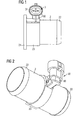
- the in Fig. 2 visible part 39 of the housing gets together with the pipe section 2, ie generated in the same process step, wherein the leads 11 are embedded in a casting material.
- the part 39 of the housing 30 and the pipe piece 2 are formed in one piece.
- the housing 30 of the plug connection 3 preferably comprises a base 33, which is monolithically connected to the pipe section 2.
- the base 33 has a curvature, which preferably follows a circular arc, which results from the course of the pipe section 2.
- the pipe section 2 is preferably produced as a molded part in a compression or injection molding process, wherein the base 33 of the plug connection 3 is preferably at least partially pressed by the molding compound.
- the plug connection 3 can be connected to a further plug connection formed complementary to it, which is conductively connected to a circuit for evaluating the measurement signals detected by the sensor head 1.
- the longitudinal axis of the plug connection 3 is arranged transversely to the longitudinal axis of the pipe section 2 in the variants shown. But it can also be aligned parallel or obliquely to the longitudinal axis of the pipe section 2.
- the sensing head 1, as in the variant according to the FIG. 3 be included in a highlight 21 of the pipe section 2, which projects into the inner opening of the pipe section, but is still a part of the pipe section.
- the sensing head 1 may alternatively as in the variant according to the FIG. 4 enclosed in the side wall of the pipe section 2 be, which preferably has no emphasis in the region of the sensing head.
- At least one good heat-conducting body 10 may preferably be embedded in metal, which touches the sensing head 1.
- a good heat-conducting body means a body whose thermal conductivity is greater than that of the environment (i.e.
- the thermally conductive body 10 is preferably completely embedded in the wall of the pipe section.
- the thermally conductive body 10 is flat, formed in this variant in the form of a partial ring.
- the thermally conductive body may also have the shape of a pot, in which preferably a part of the sensing head 1 is arranged.
- the pipe section 2 can be connected on both sides to other pipes and then becomes a component of a conduit system for carrying out a - preferably the conduit system flowing through - medium whose temperature is to be measured.
- the medium may comprise a gas or a liquid.
- the pipe section can be used as a nozzle, on the front sides hoses are mounted. End-side regions 22 of the pipe section 2 preferably have latching devices.
- the pipe section 2, which comprises the sensing head 1, has a thickening in the area 23, since in this area preferably a base of the plug connection 3 is cast.
- the pipe section 2 may have a collar 24, arranged in the openings 241 for receiving fastening elements are.
- the pipe section can be attached to a carrier.
Landscapes
- Physics & Mathematics (AREA)
- General Physics & Mathematics (AREA)
- Nonlinear Science (AREA)
- Measuring Temperature Or Quantity Of Heat (AREA)
Applications Claiming Priority (3)
| Application Number | Priority Date | Filing Date | Title |
|---|---|---|---|
| DE102006031343A DE102006031343A1 (de) | 2006-07-06 | 2006-07-06 | Temperaturmessvorrichtung |
| PCT/DE2007/001059 WO2008003280A1 (fr) | 2006-07-06 | 2007-06-15 | Dispositif de mesure de température |
| EP07764375.7A EP2038625B2 (fr) | 2006-07-06 | 2007-06-15 | Dispositif de mesure de température |
Related Parent Applications (3)
| Application Number | Title | Priority Date | Filing Date |
|---|---|---|---|
| EP07764375.7A Division-Into EP2038625B2 (fr) | 2006-07-06 | 2007-06-15 | Dispositif de mesure de température |
| EP07764375.7A Division EP2038625B2 (fr) | 2006-07-06 | 2007-06-15 | Dispositif de mesure de température |
| EP07764375.7 Division | 2007-06-15 |
Publications (2)
| Publication Number | Publication Date |
|---|---|
| EP2339309A1 true EP2339309A1 (fr) | 2011-06-29 |
| EP2339309B1 EP2339309B1 (fr) | 2019-05-08 |
Family
ID=38573070
Family Applications (4)
| Application Number | Title | Priority Date | Filing Date |
|---|---|---|---|
| EP07764375.7A Active EP2038625B2 (fr) | 2006-07-06 | 2007-06-15 | Dispositif de mesure de température |
| EP11159819.9A Active EP2339307B1 (fr) | 2006-07-06 | 2007-06-15 | Dispositif de mesure de température |
| EP11159822.3A Active EP2339309B1 (fr) | 2006-07-06 | 2007-06-15 | Dispositif de mesure de température |
| EP11159821A Withdrawn EP2339308A1 (fr) | 2006-07-06 | 2007-06-15 | Dispositif de mesure de température |
Family Applications Before (2)
| Application Number | Title | Priority Date | Filing Date |
|---|---|---|---|
| EP07764375.7A Active EP2038625B2 (fr) | 2006-07-06 | 2007-06-15 | Dispositif de mesure de température |
| EP11159819.9A Active EP2339307B1 (fr) | 2006-07-06 | 2007-06-15 | Dispositif de mesure de température |
Family Applications After (1)
| Application Number | Title | Priority Date | Filing Date |
|---|---|---|---|
| EP11159821A Withdrawn EP2339308A1 (fr) | 2006-07-06 | 2007-06-15 | Dispositif de mesure de température |
Country Status (8)
| Country | Link |
|---|---|
| US (1) | US8177425B2 (fr) |
| EP (4) | EP2038625B2 (fr) |
| JP (1) | JP2009543028A (fr) |
| KR (2) | KR101570646B1 (fr) |
| CN (2) | CN102692285B (fr) |
| DE (1) | DE102006031343A1 (fr) |
| ES (1) | ES2368957T5 (fr) |
| WO (1) | WO2008003280A1 (fr) |
Families Citing this family (17)
| Publication number | Priority date | Publication date | Assignee | Title |
|---|---|---|---|---|
| DE102008029192A1 (de) | 2008-03-13 | 2009-09-24 | Epcos Ag | Fühler zum Erfassen einer physikalischen Größe und Verfahren zur Herstellung des Fühlers |
| BRPI1016136A2 (pt) * | 2009-04-09 | 2019-09-24 | Prad Research And Development Limited | sistema par monitorar e detectar invasão de fluido de um espaço anular de uma estrutura de tubo, e método para detectar invasão de fluido de um espaço anular de uma estrutura de tubo. |
| IT1396707B1 (it) * | 2009-07-06 | 2012-12-14 | Ufi Filters Spa | Gruppo filtrante perfezionato per motori endotermici a gasolio con dispositivo riscaldatore |
| DE102009060363A1 (de) | 2009-12-24 | 2011-06-30 | Volkswagen AG, 38440 | Verbindungseinheit |
| DE102012006144B3 (de) * | 2012-03-28 | 2013-08-14 | Inor Process Ab | Temperaturmessvorrichtung |
| US9976409B2 (en) * | 2013-10-08 | 2018-05-22 | Halliburton Energy Services, Inc. | Assembly for measuring temperature of materials flowing through tubing in a well system |
| WO2015164313A1 (fr) * | 2014-04-23 | 2015-10-29 | Siemens Energy, Inc. | Procédé de détermination de température de guide d'ondes pour émetteur-récepteur acoustique utilisé dans une turbine à gaz |
| US20160003685A1 (en) * | 2014-07-03 | 2016-01-07 | Vareck Walla | Mounting Apparatus for Temperature Sensor |
| DE202015103863U1 (de) * | 2015-07-23 | 2015-08-20 | Abb Technology Ag | Oberflächentemperaturfühler |
| CN105628225B (zh) * | 2016-03-02 | 2018-12-25 | 平高集团有限公司 | 一种测温装置及使用该测温装置的gil |
| DE102019124605A1 (de) | 2019-09-12 | 2021-03-18 | Endress + Hauser Wetzer Gmbh + Co. Kg | Nicht invasives Thermometer |
| DE102019124607A1 (de) | 2019-09-12 | 2021-03-18 | Endress + Hauser Wetzer Gmbh + Co. Kg | Nicht invasives Thermometer |
| DE102019124603A1 (de) | 2019-09-12 | 2021-03-18 | Endress + Hauser Wetzer Gmbh + Co. Kg | Nicht invasives Thermometer |
| DE102019124604A1 (de) | 2019-09-12 | 2021-03-18 | Endress + Hauser Wetzer Gmbh + Co. Kg | Nicht invasives Thermometer |
| DE102019129475A1 (de) | 2019-10-31 | 2021-05-06 | Endress + Hauser Wetzer Gmbh + Co. Kg | Nicht invasives Thermometer |
| DE102021109410A1 (de) | 2021-04-14 | 2022-10-20 | Endress + Hauser Wetzer Gmbh + Co. Kg | Nicht invasives Thermometer |
| DE102022127611A1 (de) | 2022-10-19 | 2024-04-25 | Endress+Hauser Wetzer Gmbh+Co. Kg | Messaufnehmer für eine thermische Messgröße und Messstelle mit einem solchen Messaufnehmer |
Citations (5)
| Publication number | Priority date | Publication date | Assignee | Title |
|---|---|---|---|---|
| DE19608675A1 (de) * | 1996-03-06 | 1997-09-11 | Delphi Automotive Systems Gmbh | Medienführende Vorrichtung mit Temperaturmessung im Medium |
| JP2002005757A (ja) * | 2000-06-27 | 2002-01-09 | Denso Corp | 温度センサ装置 |
| WO2002071551A1 (fr) * | 2001-03-03 | 2002-09-12 | Robert Bosch Gmbh | Dispositif de connexion |
| DE10340636B3 (de) | 2003-09-03 | 2005-01-13 | Epcos Ag | Verfahren zur Herstellung eines feuchtedichten Fühlers |
| JP2006058231A (ja) * | 2004-08-23 | 2006-03-02 | Nesstech Inc | 温度計 |
Family Cites Families (16)
| Publication number | Priority date | Publication date | Assignee | Title |
|---|---|---|---|---|
| US1758532A (en) * | 1928-04-20 | 1930-05-13 | Edward D Phinney | Temperature-measuring device |
| US3167733A (en) † | 1964-02-28 | 1965-01-26 | Universal Oil Prod Co | Resistance temperature sensing element |
| US3881181A (en) * | 1973-02-22 | 1975-04-29 | Rca Corp | Semiconductor temperature sensor |
| US3848466A (en) * | 1974-01-30 | 1974-11-19 | Atomic Energy Commission | Magnetic temperature sensor |
| US3897272A (en) * | 1974-07-29 | 1975-07-29 | Honeywell Inc | Sturdy sensing apparatus for measuring the temperature of a heated rubber material during its curing process and method for making same |
| AT350300B (de) * | 1975-11-12 | 1979-05-25 | Setron Erzeugung Elektronische | Einrichtung zur temperaturmessung stroemender fluessigkeiten |
| JPS59184840U (ja) † | 1983-05-26 | 1984-12-08 | 株式会社豊田中央研究所 | 体外循環体液用温度センサ− |
| JPS63253223A (ja) * | 1987-04-09 | 1988-10-20 | Terumo Corp | 温度測定器 |
| FR2737007B1 (fr) * | 1995-07-18 | 1997-09-19 | Elf Antar France | Dispositif de mesure de la temperature d'une paroi chaude |
| KR200210049Y1 (ko) * | 1998-05-29 | 2001-03-02 | 배길호 | 교환가능한 온도측정장치의 단열구조 |
| DE29914553U1 (de) * | 1999-08-19 | 1999-12-02 | Temperaturmeßtechnik Geraberg GmbH, 98693 Martinroda | Vorrichtung zur Bestimmung der Temperatur in Rohrleitungen |
| US7249885B2 (en) * | 2002-10-16 | 2007-07-31 | Clyde Bergemann Gmbh | Heat flux measuring device for pressure pipes, method for producing a measuring device, method for monitoring an operating state of a heat exchanger, heat exchanger and method for measuring a heat flux |
| DE10314705B3 (de) * | 2003-03-31 | 2004-07-01 | Heraeus Sensor Technology Gmbh | Vorrichtung zur Bestimmung der Temperatur eines strömenden Mediums in einer Rohr- oder Schlauchleitung |
| JP2004361217A (ja) | 2003-06-04 | 2004-12-24 | Mitsubishi Electric Corp | 温度検知装置 |
| DE10357222A1 (de) * | 2003-12-08 | 2005-06-30 | Basf Ag | Anschlussstutzen für Messgeräte und mit einem solchen Anschlussstutzen versehene Messsonde |
| CN2757103Y (zh) * | 2004-11-25 | 2006-02-08 | 李春 | 管卡安装型温度传感器 |
-
2006
- 2006-07-06 DE DE102006031343A patent/DE102006031343A1/de not_active Ceased
-
2007
- 2007-06-15 ES ES07764375.7T patent/ES2368957T5/es active Active
- 2007-06-15 WO PCT/DE2007/001059 patent/WO2008003280A1/fr active Application Filing
- 2007-06-15 EP EP07764375.7A patent/EP2038625B2/fr active Active
- 2007-06-15 KR KR1020157003720A patent/KR101570646B1/ko active IP Right Grant
- 2007-06-15 JP JP2009516881A patent/JP2009543028A/ja active Pending
- 2007-06-15 EP EP11159819.9A patent/EP2339307B1/fr active Active
- 2007-06-15 EP EP11159822.3A patent/EP2339309B1/fr active Active
- 2007-06-15 CN CN201210181200.2A patent/CN102692285B/zh not_active Expired - Fee Related
- 2007-06-15 KR KR1020097002388A patent/KR101633124B1/ko active IP Right Grant
- 2007-06-15 EP EP11159821A patent/EP2339308A1/fr not_active Withdrawn
- 2007-06-15 CN CNA2007800255757A patent/CN101484786A/zh active Pending
-
2009
- 2009-01-05 US US12/348,713 patent/US8177425B2/en not_active Expired - Fee Related
Patent Citations (5)
| Publication number | Priority date | Publication date | Assignee | Title |
|---|---|---|---|---|
| DE19608675A1 (de) * | 1996-03-06 | 1997-09-11 | Delphi Automotive Systems Gmbh | Medienführende Vorrichtung mit Temperaturmessung im Medium |
| JP2002005757A (ja) * | 2000-06-27 | 2002-01-09 | Denso Corp | 温度センサ装置 |
| WO2002071551A1 (fr) * | 2001-03-03 | 2002-09-12 | Robert Bosch Gmbh | Dispositif de connexion |
| DE10340636B3 (de) | 2003-09-03 | 2005-01-13 | Epcos Ag | Verfahren zur Herstellung eines feuchtedichten Fühlers |
| JP2006058231A (ja) * | 2004-08-23 | 2006-03-02 | Nesstech Inc | 温度計 |
Also Published As
| Publication number | Publication date |
|---|---|
| WO2008003280A1 (fr) | 2008-01-10 |
| EP2339308A1 (fr) | 2011-06-29 |
| EP2339307A1 (fr) | 2011-06-29 |
| US8177425B2 (en) | 2012-05-15 |
| ES2368957T5 (es) | 2015-06-18 |
| CN102692285A (zh) | 2012-09-26 |
| CN101484786A (zh) | 2009-07-15 |
| KR101633124B1 (ko) | 2016-06-23 |
| KR20090045226A (ko) | 2009-05-07 |
| EP2038625B2 (fr) | 2015-05-20 |
| US20090193887A1 (en) | 2009-08-06 |
| EP2038625A1 (fr) | 2009-03-25 |
| CN102692285B (zh) | 2015-08-12 |
| ES2368957T3 (es) | 2011-11-24 |
| DE102006031343A1 (de) | 2008-01-10 |
| KR101570646B1 (ko) | 2015-11-20 |
| EP2339307B1 (fr) | 2016-12-28 |
| EP2038625B1 (fr) | 2011-08-10 |
| JP2009543028A (ja) | 2009-12-03 |
| EP2339309B1 (fr) | 2019-05-08 |
| KR20150028360A (ko) | 2015-03-13 |
Similar Documents
| Publication | Publication Date | Title |
|---|---|---|
| EP2339307B1 (fr) | Dispositif de mesure de température | |
| DE19534887B4 (de) | Temperaturfühler | |
| DE102004013582B4 (de) | Verfahren zur Befestigung eines Temperatursensors in einer Drucksensorvorrichtung | |
| DE19522067C2 (de) | Kraftstoffeinspritzsammelleitung | |
| DE102010019303B4 (de) | Strömungsrate-Messvorrichtung | |
| WO2014037257A2 (fr) | Dispositif de mesure de température pour déterminer la température à la surface d'une canalisation | |
| DE102010020338A1 (de) | Gehäuseanordnung für Ultraschall-Durchflussmesser sowie Ultaschall-Durchflussmesser | |
| DE102007056544A1 (de) | Sensoranordnung zur Bestimmung eines Tankfüllstands und Verfahren zur Herstellung hierzu | |
| DE112013002972T5 (de) | Thermischer Durchflussmesser | |
| DE202014100330U1 (de) | Thermischer Durchflussmesser | |
| DE102013211479B4 (de) | Vorrichtung zur Erfassung eines Drucks und einer Temperatur eines Mediums | |
| DE19815656A1 (de) | Meßvorrichtung zum Messen der Masse eines strömenden Mediums | |
| DE102006003602B4 (de) | Oberflächensensor, Sensoranordnung und Klimaanlage | |
| EP2072967B1 (fr) | Capteur électronique et procédé de fabrication d'un capteur | |
| DE202013007490U1 (de) | Temperatursensor für ein Fluid | |
| DE202012002894U1 (de) | Wärmepumpe mit einem Halter für Drucksensoren | |
| WO2019063175A1 (fr) | Bague d'étanchéité comprenant un capteur, liaison fluidique, circuit de refroidissement et procédé de fabrication d'un joint d'étanchéité | |
| DE102011089942A1 (de) | Aufnahmevorrichtung für einen Messeinsatz | |
| DE102008032309B4 (de) | Sensoranordnung zur Messung des Zustands einer Flüssigkeit, insbesondere von Öl | |
| DE102007037549A1 (de) | Gassensor zur Befestigung einer physikalischen Eigenschaft eines Messgases | |
| DE102014103314B4 (de) | Abgasrohrflansch, Gruppenflansch und Abgasanlage | |
| DE102004018354A1 (de) | Messfühler | |
| DE102012204646A1 (de) | Vorrichtung zur Erfassung eines Drucks und einer Temperatur eines Fluids | |
| DE102014001640A1 (de) | Druck- und Temperatursensor-Element | |
| EP2895833A2 (fr) | Capteur haute température doté d'un tuyau protecteur dans la section froide |
Legal Events
| Date | Code | Title | Description |
|---|---|---|---|
| PUAI | Public reference made under article 153(3) epc to a published international application that has entered the european phase |
Free format text: ORIGINAL CODE: 0009012 |
|
| AC | Divisional application: reference to earlier application |
Ref document number: 2038625 Country of ref document: EP Kind code of ref document: P |
|
| AK | Designated contracting states |
Kind code of ref document: A1 Designated state(s): DE ES FR GB IT |
|
| 17P | Request for examination filed |
Effective date: 20111222 |
|
| RBV | Designated contracting states (corrected) |
Designated state(s): DE ES FR GB IT |
|
| 17Q | First examination report despatched |
Effective date: 20160801 |
|
| RAP1 | Party data changed (applicant data changed or rights of an application transferred) |
Owner name: EPCOS AG |
|
| RAP1 | Party data changed (applicant data changed or rights of an application transferred) |
Owner name: TDK ELECTRONICS AG |
|
| GRAP | Despatch of communication of intention to grant a patent |
Free format text: ORIGINAL CODE: EPIDOSNIGR1 |
|
| INTG | Intention to grant announced |
Effective date: 20181205 |
|
| RIN1 | Information on inventor provided before grant (corrected) |
Inventor name: BALZER, PETER Inventor name: GRUNDMANN, WOLFGANG Inventor name: OSTRICK, BERNHARD |
|
| GRAS | Grant fee paid |
Free format text: ORIGINAL CODE: EPIDOSNIGR3 |
|
| GRAA | (expected) grant |
Free format text: ORIGINAL CODE: 0009210 |
|
| AC | Divisional application: reference to earlier application |
Ref document number: 2038625 Country of ref document: EP Kind code of ref document: P |
|
| AK | Designated contracting states |
Kind code of ref document: B1 Designated state(s): DE ES FR GB IT |
|
| REG | Reference to a national code |
Ref country code: GB Ref legal event code: FG4D Free format text: NOT ENGLISH |
|
| REG | Reference to a national code |
Ref country code: DE Ref legal event code: R096 Ref document number: 502007016676 Country of ref document: DE |
|
| PG25 | Lapsed in a contracting state [announced via postgrant information from national office to epo] |
Ref country code: ES Free format text: LAPSE BECAUSE OF FAILURE TO SUBMIT A TRANSLATION OF THE DESCRIPTION OR TO PAY THE FEE WITHIN THE PRESCRIBED TIME-LIMIT Effective date: 20190508 |
|
| REG | Reference to a national code |
Ref country code: DE Ref legal event code: R097 Ref document number: 502007016676 Country of ref document: DE |
|
| PG25 | Lapsed in a contracting state [announced via postgrant information from national office to epo] |
Ref country code: IT Free format text: LAPSE BECAUSE OF FAILURE TO SUBMIT A TRANSLATION OF THE DESCRIPTION OR TO PAY THE FEE WITHIN THE PRESCRIBED TIME-LIMIT Effective date: 20190508 |
|
| PLBE | No opposition filed within time limit |
Free format text: ORIGINAL CODE: 0009261 |
|
| STAA | Information on the status of an ep patent application or granted ep patent |
Free format text: STATUS: NO OPPOSITION FILED WITHIN TIME LIMIT |
|
| 26N | No opposition filed |
Effective date: 20200211 |
|
| GBPC | Gb: european patent ceased through non-payment of renewal fee |
Effective date: 20190808 |
|
| PG25 | Lapsed in a contracting state [announced via postgrant information from national office to epo] |
Ref country code: FR Free format text: LAPSE BECAUSE OF NON-PAYMENT OF DUE FEES Effective date: 20190708 |
|
| PG25 | Lapsed in a contracting state [announced via postgrant information from national office to epo] |
Ref country code: GB Free format text: LAPSE BECAUSE OF NON-PAYMENT OF DUE FEES Effective date: 20190808 |
|
| P01 | Opt-out of the competence of the unified patent court (upc) registered |
Effective date: 20230521 |
|
| PGFP | Annual fee paid to national office [announced via postgrant information from national office to epo] |
Ref country code: DE Payment date: 20240620 Year of fee payment: 18 |