EP2037226A2 - Procédé et dispositif destinés à la détermination de la position d'un véhicule - Google Patents
Procédé et dispositif destinés à la détermination de la position d'un véhicule Download PDFInfo
- Publication number
- EP2037226A2 EP2037226A2 EP20080005213 EP08005213A EP2037226A2 EP 2037226 A2 EP2037226 A2 EP 2037226A2 EP 20080005213 EP20080005213 EP 20080005213 EP 08005213 A EP08005213 A EP 08005213A EP 2037226 A2 EP2037226 A2 EP 2037226A2
- Authority
- EP
- European Patent Office
- Prior art keywords
- vehicle
- digital camera
- markers
- marker
- determined
- Prior art date
- Legal status (The legal status is an assumption and is not a legal conclusion. Google has not performed a legal analysis and makes no representation as to the accuracy of the status listed.)
- Granted
Links
- 238000000034 method Methods 0.000 title claims description 42
- 239000003550 marker Substances 0.000 claims abstract description 32
- 238000001514 detection method Methods 0.000 claims abstract description 24
- 238000004590 computer program Methods 0.000 claims abstract description 16
- 239000000969 carrier Substances 0.000 claims abstract description 7
- 238000012545 processing Methods 0.000 claims abstract description 7
- 238000006073 displacement reaction Methods 0.000 claims description 8
- 238000011156 evaluation Methods 0.000 claims description 6
- 238000011109 contamination Methods 0.000 description 2
- 238000012423 maintenance Methods 0.000 description 2
- 238000003672 processing method Methods 0.000 description 2
- 238000005303 weighing Methods 0.000 description 2
- 230000032683 aging Effects 0.000 description 1
- 230000004888 barrier function Effects 0.000 description 1
- 238000005452 bending Methods 0.000 description 1
- 238000004364 calculation method Methods 0.000 description 1
- 230000001419 dependent effect Effects 0.000 description 1
- 238000011161 development Methods 0.000 description 1
- 230000018109 developmental process Effects 0.000 description 1
- 238000010191 image analysis Methods 0.000 description 1
- 238000009776 industrial production Methods 0.000 description 1
- 238000004519 manufacturing process Methods 0.000 description 1
- 238000005259 measurement Methods 0.000 description 1
- 230000003287 optical effect Effects 0.000 description 1
- 238000012856 packing Methods 0.000 description 1
Images
Classifications
-
- G—PHYSICS
- G01—MEASURING; TESTING
- G01D—MEASURING NOT SPECIALLY ADAPTED FOR A SPECIFIC VARIABLE; ARRANGEMENTS FOR MEASURING TWO OR MORE VARIABLES NOT COVERED IN A SINGLE OTHER SUBCLASS; TARIFF METERING APPARATUS; MEASURING OR TESTING NOT OTHERWISE PROVIDED FOR
- G01D5/00—Mechanical means for transferring the output of a sensing member; Means for converting the output of a sensing member to another variable where the form or nature of the sensing member does not constrain the means for converting; Transducers not specially adapted for a specific variable
- G01D5/26—Mechanical means for transferring the output of a sensing member; Means for converting the output of a sensing member to another variable where the form or nature of the sensing member does not constrain the means for converting; Transducers not specially adapted for a specific variable characterised by optical transfer means, i.e. using infrared, visible, or ultraviolet light
-
- B—PERFORMING OPERATIONS; TRANSPORTING
- B61—RAILWAYS
- B61L—GUIDING RAILWAY TRAFFIC; ENSURING THE SAFETY OF RAILWAY TRAFFIC
- B61L25/00—Recording or indicating positions or identities of vehicles or trains or setting of track apparatus
- B61L25/02—Indicating or recording positions or identities of vehicles or trains
- B61L25/025—Absolute localisation, e.g. providing geodetic coordinates
-
- B—PERFORMING OPERATIONS; TRANSPORTING
- B66—HOISTING; LIFTING; HAULING
- B66C—CRANES; LOAD-ENGAGING ELEMENTS OR DEVICES FOR CRANES, CAPSTANS, WINCHES, OR TACKLES
- B66C13/00—Other constructional features or details
- B66C13/16—Applications of indicating, registering, or weighing devices
-
- B—PERFORMING OPERATIONS; TRANSPORTING
- B66—HOISTING; LIFTING; HAULING
- B66C—CRANES; LOAD-ENGAGING ELEMENTS OR DEVICES FOR CRANES, CAPSTANS, WINCHES, OR TACKLES
- B66C13/00—Other constructional features or details
- B66C13/18—Control systems or devices
- B66C13/46—Position indicators for suspended loads or for crane elements
-
- G—PHYSICS
- G01—MEASURING; TESTING
- G01D—MEASURING NOT SPECIALLY ADAPTED FOR A SPECIFIC VARIABLE; ARRANGEMENTS FOR MEASURING TWO OR MORE VARIABLES NOT COVERED IN A SINGLE OTHER SUBCLASS; TARIFF METERING APPARATUS; MEASURING OR TESTING NOT OTHERWISE PROVIDED FOR
- G01D5/00—Mechanical means for transferring the output of a sensing member; Means for converting the output of a sensing member to another variable where the form or nature of the sensing member does not constrain the means for converting; Transducers not specially adapted for a specific variable
- G01D5/12—Mechanical means for transferring the output of a sensing member; Means for converting the output of a sensing member to another variable where the form or nature of the sensing member does not constrain the means for converting; Transducers not specially adapted for a specific variable using electric or magnetic means
- G01D5/244—Mechanical means for transferring the output of a sensing member; Means for converting the output of a sensing member to another variable where the form or nature of the sensing member does not constrain the means for converting; Transducers not specially adapted for a specific variable using electric or magnetic means influencing characteristics of pulses or pulse trains; generating pulses or pulse trains
- G01D5/249—Mechanical means for transferring the output of a sensing member; Means for converting the output of a sensing member to another variable where the form or nature of the sensing member does not constrain the means for converting; Transducers not specially adapted for a specific variable using electric or magnetic means influencing characteristics of pulses or pulse trains; generating pulses or pulse trains using pulse code
- G01D5/2497—Absolute encoders
-
- G—PHYSICS
- G01—MEASURING; TESTING
- G01D—MEASURING NOT SPECIALLY ADAPTED FOR A SPECIFIC VARIABLE; ARRANGEMENTS FOR MEASURING TWO OR MORE VARIABLES NOT COVERED IN A SINGLE OTHER SUBCLASS; TARIFF METERING APPARATUS; MEASURING OR TESTING NOT OTHERWISE PROVIDED FOR
- G01D5/00—Mechanical means for transferring the output of a sensing member; Means for converting the output of a sensing member to another variable where the form or nature of the sensing member does not constrain the means for converting; Transducers not specially adapted for a specific variable
- G01D5/26—Mechanical means for transferring the output of a sensing member; Means for converting the output of a sensing member to another variable where the form or nature of the sensing member does not constrain the means for converting; Transducers not specially adapted for a specific variable characterised by optical transfer means, i.e. using infrared, visible, or ultraviolet light
- G01D5/32—Mechanical means for transferring the output of a sensing member; Means for converting the output of a sensing member to another variable where the form or nature of the sensing member does not constrain the means for converting; Transducers not specially adapted for a specific variable characterised by optical transfer means, i.e. using infrared, visible, or ultraviolet light with attenuation or whole or partial obturation of beams of light
- G01D5/34—Mechanical means for transferring the output of a sensing member; Means for converting the output of a sensing member to another variable where the form or nature of the sensing member does not constrain the means for converting; Transducers not specially adapted for a specific variable characterised by optical transfer means, i.e. using infrared, visible, or ultraviolet light with attenuation or whole or partial obturation of beams of light the beams of light being detected by photocells
- G01D5/347—Mechanical means for transferring the output of a sensing member; Means for converting the output of a sensing member to another variable where the form or nature of the sensing member does not constrain the means for converting; Transducers not specially adapted for a specific variable characterised by optical transfer means, i.e. using infrared, visible, or ultraviolet light with attenuation or whole or partial obturation of beams of light the beams of light being detected by photocells using displacement encoding scales
- G01D5/34746—Linear encoders
-
- G—PHYSICS
- G01—MEASURING; TESTING
- G01D—MEASURING NOT SPECIALLY ADAPTED FOR A SPECIFIC VARIABLE; ARRANGEMENTS FOR MEASURING TWO OR MORE VARIABLES NOT COVERED IN A SINGLE OTHER SUBCLASS; TARIFF METERING APPARATUS; MEASURING OR TESTING NOT OTHERWISE PROVIDED FOR
- G01D5/00—Mechanical means for transferring the output of a sensing member; Means for converting the output of a sensing member to another variable where the form or nature of the sensing member does not constrain the means for converting; Transducers not specially adapted for a specific variable
- G01D5/26—Mechanical means for transferring the output of a sensing member; Means for converting the output of a sensing member to another variable where the form or nature of the sensing member does not constrain the means for converting; Transducers not specially adapted for a specific variable characterised by optical transfer means, i.e. using infrared, visible, or ultraviolet light
- G01D5/32—Mechanical means for transferring the output of a sensing member; Means for converting the output of a sensing member to another variable where the form or nature of the sensing member does not constrain the means for converting; Transducers not specially adapted for a specific variable characterised by optical transfer means, i.e. using infrared, visible, or ultraviolet light with attenuation or whole or partial obturation of beams of light
- G01D5/34—Mechanical means for transferring the output of a sensing member; Means for converting the output of a sensing member to another variable where the form or nature of the sensing member does not constrain the means for converting; Transducers not specially adapted for a specific variable characterised by optical transfer means, i.e. using infrared, visible, or ultraviolet light with attenuation or whole or partial obturation of beams of light the beams of light being detected by photocells
- G01D5/347—Mechanical means for transferring the output of a sensing member; Means for converting the output of a sensing member to another variable where the form or nature of the sensing member does not constrain the means for converting; Transducers not specially adapted for a specific variable characterised by optical transfer means, i.e. using infrared, visible, or ultraviolet light with attenuation or whole or partial obturation of beams of light the beams of light being detected by photocells using displacement encoding scales
- G01D5/34776—Absolute encoders with analogue or digital scales
-
- G—PHYSICS
- G05—CONTROLLING; REGULATING
- G05D—SYSTEMS FOR CONTROLLING OR REGULATING NON-ELECTRIC VARIABLES
- G05D1/00—Control of position, course, altitude or attitude of land, water, air or space vehicles, e.g. using automatic pilots
- G05D1/02—Control of position or course in two dimensions
- G05D1/021—Control of position or course in two dimensions specially adapted to land vehicles
- G05D1/0231—Control of position or course in two dimensions specially adapted to land vehicles using optical position detecting means
- G05D1/0234—Control of position or course in two dimensions specially adapted to land vehicles using optical position detecting means using optical markers or beacons
-
- G—PHYSICS
- G01—MEASURING; TESTING
- G01D—MEASURING NOT SPECIALLY ADAPTED FOR A SPECIFIC VARIABLE; ARRANGEMENTS FOR MEASURING TWO OR MORE VARIABLES NOT COVERED IN A SINGLE OTHER SUBCLASS; TARIFF METERING APPARATUS; MEASURING OR TESTING NOT OTHERWISE PROVIDED FOR
- G01D2205/00—Indexing scheme relating to details of means for transferring or converting the output of a sensing member
- G01D2205/90—Two-dimensional encoders, i.e. having one or two codes extending in two directions
Definitions
- the present invention relates in a first aspect to a method for determining the position of a vehicle according to the preamble of claim 1.
- the invention relates to a device for determining the position of a vehicle according to the preamble of claim 11.
- the invention relates to a computer program and a computer program product.
- a generic method is for example in DE 199 10 933 A1 disclosed.
- a vehicle is moved along a path, which can in principle run along an arbitrary curve, and, for position determination, one-dimensional barcodes are arranged as markers along the path.
- the invention relates in particular to vehicles such as monorail conveyors, stacker cranes, cranes or other movable devices that are movable along a path or on or parallel to a predetermined surface.
- the achievable accuracy of the position determination is limited by the length of the code marks or their elements, since the code elements are lined up in one or more parallel tracks along the guideway and must be scanned sequentially during the process.
- the packing density of the code elements on the code carrier can not be increased beyond a certain extent, because the spatial resolution of the sensing elements, such as light barriers, is limited. The length the code carrier can therefore not be reduced below a certain minimum value, so that the position resolution limits are set.
- an object of the invention can be considered to provide a method and apparatus to provide improved position resolution and allow longer travel distances. Furthermore, information should also be provided as to whether and, if appropriate, how far the vehicle deviates from a normal orbit. In addition, a suitable computer program should be specified.
- the object is achieved by the device having the features of claim 11.
- the method of the above-mentioned type is inventively further developed in that the markers are detected with a camera arranged on the digital camera and that by means of image processing from a position of at least one marker image in the detection range of the digital camera, a relative position of the vehicle with respect to the respective marker or the respective marker in Direction of a main movement direction of the vehicle along the path and in at least one direction transverse to the main direction of movement of the vehicle is determined.
- the device of the above type is further developed according to the invention by a digital camera to be arranged on the vehicle for detecting markers arranged along the track and a computer connected to the digital camera, which is arranged to determine a relative position of the vehicle with respect to at least one marker in the direction of a main movement direction of Vehicle along the path and in at least one direction transverse to the main movement direction by means of image processing from a position of the image of the respective marker or the respective marker in a detection range of the digital camera.
- a position determination of a vehicle is possible in a very precise manner by determining and evaluating the position or position of a particular marker in a detection area of a digital camera.
- the method according to the invention which is an incident light method, can in particular also provide position information for a stationary vehicle.
- Another essential advantage of the invention can be seen in that, in contrast to methods from the prior art, a position determination transversely to the direction of travel or movement is possible and carried out.
- the position information transversely to the direction of travel can be used particularly advantageously for an automatic compensation of temperature or load change-related bending deformations.
- Another advantage of the invention can also be seen in the fact that previously necessary scanning elements, such as photoelectric sensors, which are prone to maladjustment and contamination and thus maintenance-intensive, are no longer necessary.
- This advantage comes in a special way to bear, where at many locations of the web a position determination is to be performed transversely to the direction of travel. For this purpose, a variety of scanning had previously been arranged side by side.
- all graphically representable coding and marking types can be used as markers, the structures of which and therefore the information contained therein can be recognized and evaluated with a digital camera.
- barcodes in particular two-dimensional barcodes, are used.
- a determined relative position with respect to a certain marker can in principle be unambiguously assigned to a specific absolute position of the vehicle, it is furthermore preferred if the markers used are different, ie can be clearly distinguished by means of image processing.
- the range of detectable changes in position transverse to a main direction of movement of the vehicle is increased when the markers are arranged in multiple rows along the path.
- a digital camera basically known and available components can be used, for example, it can be a digital camera with a CCD or a CMOS receiver chip.
- changes in the marker images in the detection area of the digital camera change the position of the vehicle transversely to the main direction of movement of the vehicle certainly.
- Such displacements which occur, for example, when the vehicle moves at substantially constant distance from the web laterally to the main movement direction can be easily determined and quantitatively evaluated with methods of image recognition and image analysis.
- the main direction of movement is referred to herein as the x-direction.
- the direction considered here laterally to the main movement direction is also referred to as y-direction.
- changes in the size of the marker images can be used to determine changes in the distance of the vehicle from the path. Such changes in the distance of the vehicle to the path correspond to a movement of the vehicle in the z-direction.
- a reference run is preferably carried out at least once during a system startup in which relative positions of the vehicle relating to relative positions of the vehicle in the main movement direction are recorded and stored transversely to the main movement direction in at least one direction.
- error signals are output, for example, if the values determined for the relative positions of the vehicle in directions transverse to the main movement direction leave predetermined tolerance intervals.
- the method according to the invention can be determined from shifts of marker images in the detection range of the digital camera, a weight of a load with which the vehicle is acted upon.
- the measuring device can accordingly also serve as a scale for vehicles which are intended for the transport of loads.
- the digital camera is coupled to a component of the vehicle, which is elastically deformable upon application of the vehicle with a load to be transported.
- the digital camera can be coupled with a spring which is mounted on a base frame or base support of the vehicle.
- the method according to the invention and the device according to the invention can be used particularly advantageously in vehicles which rely on rollers on their own moving each track. Such rollers wear off over time and must be replaced. On the one hand, a failure of the rollers and thus of the vehicle should be prevented. On the other hand, the rollers should be able to be used practically to the end of their life.
- This variant of the method can also be used, in particular, when a weighing is performed when the vehicle is subjected to a load.
- the method according to the invention can also be carried out in this way and the computer program according to the invention can accordingly be constructed in such a way that initially no identification of the individual markers takes place during evaluation.
- the position information is then obtained by counting proven characteristic structures, for example by counting the detected edges.
- the position information can be provided particularly quickly, since comparatively few pixels may be sufficient to detect only the characteristic structures.
- the prerequisite for this is that the distances between the markers are known to each other.
- the markers are arranged equidistant from one another along the path for this purpose.
- the distance between individual two-dimensional barcodes is at least as large as the smallest structure occurring in the barcodes, ie at least as large as a minimum information unit, in particular at least as large as one bit, the two-dimensional barcode.
- an absolute position of the vehicle can additionally be determined from the relative position with respect to a specific marker and a known absolute position of this marker. for example, based on a specific point in a production hall.
- the absolute position can be output directly and passed on, for example, from a programmable logic controller to other components.
- the calculation and evaluation steps of the method according to the invention are preferably carried out on the computer as a computer program.
- this computer program can be stored on a computer-readable data carrier, in particular in a ROM of a microcontroller or a programmable logic module.
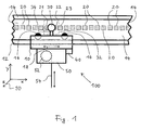
- FIG. 1 Shown there is a vehicle 10 which is movable on a support 14 by means of rollers 16 and a drive not shown here. Vehicles of in FIG. 1 shown type are also referred to as trolleys.
- the carrier 14 forms a track 12 along which the vehicle 10 is movable.
- the moving direction or main moving direction of the vehicle 10 is in FIG. 1 the x-direction and indicated by a double arrow 18.
- a cable winch 52 shown schematically here, is positioned with which loads are transported and transported via a cable 54 can.
- the spatial directions are also indicated by a coordinate system 90.
- the device 100 comprises as essential components a digital camera 30 and a computing device 40, with which the digital camera 30 is operatively connected, typically by connecting cable.
- the computing device 40 may also be integrated into the digital camera 30.
- the digital camera 30 is rigidly connected to the vehicle 10 via a holding arm 34.
- a here essentially square detection area 32 of the digital camera 30 is also shown schematically.
- a computer program product in the sense of the invention may in particular be the computing device 40 itself with associated ROM memory.
- An essential component of the optical positioning system according to the invention described here are also a multiplicity of in each case in each case different markers 20, which in the example shown are two-dimensional barcodes. These markers 20 are mounted equidistantly along the carrier 14. Typically these are glued tapes printed with the barcodes. In the situation shown, the markers 21 and 22 are completely detected by the digital camera 30. In addition, an edge area of the marker 23 is detected.
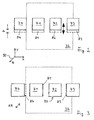
- the method according to the invention is based, in an essential aspect, on the utilization of data resulting from the image processing and indications of a y-deflection or a z-displacement for further evaluations.
- a y-deflection can, for example, result from a displacement of the marker images within the detection area 32 of the camera 30.
- a detection area 32 of a digital camera 30 is shown.
- the images 71, 72 of two barcodes completely fall into the detection area 32 of the digital camera 30.
- the image 73 of another barcode is still half in the detection area 32 and the image 74 of another barcode is finally completely outside the detection area 32.
- the marker images 71 , 72, 73, 74 are in the example shown over original positions, which are indicated by the reference numerals 81, 82, 83, 84, shifted upward. This was caused by a downward displacement of the digital camera 30, for example due to worn wheels of the vehicle. From a displacement ⁇ of the marker images 71, 72, 73, 74 in the detection region 32 of the digital camera 30, a displacement ⁇ y of the vehicle 10 in the y-direction is then quantitatively determined according to the invention.
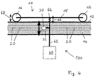
- Fig. 3 explains how a movement in the z-direction can be detected.
- Fig. 3 shows a situation in which the camera is closer than normal to the barcodes 20. Accordingly, the marker images 71, 72, 73, 74 of the bar codes are enlarged and shifted beyond the original images 81, 82, 83, 84. From the ascertained change in size of the marker images 71, 72, 73, 74, a change in distance ⁇ z of the vehicle 10 in the z-direction is then calculated according to the invention.
- the wear of rollers of a monorail conveyor can be determined and the corresponding monorail conveyor Thus, it can be supplied in time for a perfect wear and therefore timely before a failure maintenance.
- FIG. 4 Here is shown schematically another embodiment of a device 100 according to the invention on a vehicle 10.
- vehicle 10 which in the example shown is a monorail monorail, is designed to carry loads 60 and can roll on a carrier 14 with the aid of rollers 16.
- a digital camera 30 is mounted on a load arm 62 on which a load 60 to be transported is suspended.
- the load arm 62 is connected via a spring 64 to a base frame 15 of the vehicle 10, which may also be referred to as a car.
- a weighing method can also be realized via the y-position.
- the device 100 can be coupled to the vehicle 10, for example a monorail, in such a way that the digital camera 30 shifts with a changing load 60.
- the digital camera 30 is coupled via a spring 64 to the base support 15 of the vehicle. Proportional to the weight, the digital camera 30 accordingly moves down. When the load 60 is removed again, the digital camera 30 moves up again accordingly.
- the direction of movement of the digital camera 30 when using the device 100 according to the invention as a scale is in Fig. 4 indicated by a double arrow 66.
- the determined diagnostic data can also be used for other applications.
- the positions of the respective bar codes can be set via the y position and the z position during each drive, in particular during a first startup of a measuring system.
- a complete system can also be very well monitored with these two values against wear and signs of aging. For example, during a reference run, the y and z positions are stored for each x position.
- the newly recorded data are compared with those of the reference run. If deviations are present or the deviations exceed predetermined tolerance intervals, a superordinate computing or control device, for example a programmable logic controller, can be notified and the system can be included in the next service interval in time for maintenance, without a failure of the operation.
- a superordinate computing or control device for example a programmable logic controller
- the present invention provides a new method and apparatus for determining the position of a vehicle. With the help of basically known components, the position of vehicles is determined here in a simple, reliable and trouble-free manner. Compared with the prior art, considerably longer travel paths are possible, and a particular advantage is that even deviations from the normal path can be detected and output transversely to a main direction of movement.
- the invention has been described above for monorail overhead conveyors in further detail, but can also be used in other systems in a corresponding manner.
Landscapes
- Engineering & Computer Science (AREA)
- Physics & Mathematics (AREA)
- General Physics & Mathematics (AREA)
- Mechanical Engineering (AREA)
- Automation & Control Theory (AREA)
- Electromagnetism (AREA)
- Aviation & Aerospace Engineering (AREA)
- Radar, Positioning & Navigation (AREA)
- Remote Sensing (AREA)
- Length Measuring Devices By Optical Means (AREA)
- Image Analysis (AREA)
Priority Applications (2)
| Application Number | Priority Date | Filing Date | Title |
|---|---|---|---|
| JP2008227818A JP5207887B2 (ja) | 2007-09-12 | 2008-09-05 | 車両の位置を決定する方法および装置、コンピュータプログラムおよびコンピュータプログラム製品 |
| US12/207,589 US8385594B2 (en) | 2007-09-12 | 2008-09-10 | Method and apparatus for determining the position of a vehicle, computer program and computer program product |
Applications Claiming Priority (2)
| Application Number | Priority Date | Filing Date | Title |
|---|---|---|---|
| DE200720012798 DE202007012798U1 (de) | 2007-09-12 | 2007-09-12 | Positioniersysteme |
| DE102007043498A DE102007043498A1 (de) | 2007-09-12 | 2007-09-12 | Verfahren zur Positionierung eines Fahrzeugs sowie Positioniersysteme |
Publications (3)
| Publication Number | Publication Date |
|---|---|
| EP2037226A2 true EP2037226A2 (fr) | 2009-03-18 |
| EP2037226A3 EP2037226A3 (fr) | 2009-08-12 |
| EP2037226B1 EP2037226B1 (fr) | 2016-02-17 |
Family
ID=39670412
Family Applications (6)
| Application Number | Title | Priority Date | Filing Date |
|---|---|---|---|
| EP08005213.7A Active EP2037226B1 (fr) | 2007-09-12 | 2008-03-19 | Procédé et dispositif destinés à la détermination de la position d`un véhicule, programme informatique et produit de programme informatique |
| EP08005214.5A Active EP2037224B1 (fr) | 2007-09-12 | 2008-03-19 | Procédé et dispositif destinés à la détermination de la position d'un véhicule, programme informatique et produit de programme informatique |
| EP08005216A Active EP2037225B1 (fr) | 2007-09-12 | 2008-03-19 | Procédé et dispositif destinés à la détermination de la position d'un véhicule, programme informatique et produit de programme informatique |
| EP08005215.2A Active EP2037227B1 (fr) | 2007-09-12 | 2008-03-19 | Procédé et dispositif destinés à la détermination de la position d'un véhicule |
| EP08005217.8A Active EP2037228B1 (fr) | 2007-09-12 | 2008-03-19 | Procédé et dispositif destinés à la détermination d'un intervalle de maintenance d'un véhicule, programme informatique et produit de programme informatique |
| EP08005218A Withdrawn EP2037229A1 (fr) | 2007-09-12 | 2008-03-19 | Procédé et dispositif pour déterminer la position d'un véhicule |
Family Applications After (5)
| Application Number | Title | Priority Date | Filing Date |
|---|---|---|---|
| EP08005214.5A Active EP2037224B1 (fr) | 2007-09-12 | 2008-03-19 | Procédé et dispositif destinés à la détermination de la position d'un véhicule, programme informatique et produit de programme informatique |
| EP08005216A Active EP2037225B1 (fr) | 2007-09-12 | 2008-03-19 | Procédé et dispositif destinés à la détermination de la position d'un véhicule, programme informatique et produit de programme informatique |
| EP08005215.2A Active EP2037227B1 (fr) | 2007-09-12 | 2008-03-19 | Procédé et dispositif destinés à la détermination de la position d'un véhicule |
| EP08005217.8A Active EP2037228B1 (fr) | 2007-09-12 | 2008-03-19 | Procédé et dispositif destinés à la détermination d'un intervalle de maintenance d'un véhicule, programme informatique et produit de programme informatique |
| EP08005218A Withdrawn EP2037229A1 (fr) | 2007-09-12 | 2008-03-19 | Procédé et dispositif pour déterminer la position d'un véhicule |
Country Status (3)
| Country | Link |
|---|---|
| EP (6) | EP2037226B1 (fr) |
| AT (1) | ATE522788T1 (fr) |
| ES (4) | ES2564810T3 (fr) |
Cited By (6)
| Publication number | Priority date | Publication date | Assignee | Title |
|---|---|---|---|---|
| DE102010008957A1 (de) * | 2010-02-19 | 2011-08-25 | FusionSystems GmbH, 09125 | Positionsbestimmung mittels optischer Kode-Schiene (Astropos) |
| WO2015090847A1 (fr) * | 2013-12-17 | 2015-06-25 | Robert Bosch Gmbh | Guidage linéaire à mesure de charge et de position combinée |
| US9354070B2 (en) | 2013-10-31 | 2016-05-31 | Crown Equipment Corporation | Systems, methods, and industrial vehicles for determining the visibility of features |
| WO2017149357A1 (fr) * | 2016-03-02 | 2017-09-08 | Auto Drive Solutions S.L. | Moyens d'information codée situés dans une infrastructure prévus pour être décodés par des capteurs situés sur des véhicules ou objets mobiles |
| CN108803603A (zh) * | 2018-06-05 | 2018-11-13 | 广州市远能物流自动化设备科技有限公司 | 基于编码图像的agv小车对接定位方法及agv小车 |
| EP3527952A1 (fr) * | 2018-02-14 | 2019-08-21 | Aeolus Robotics Corporation Limited | Codeur optique et son procédé de fonctionnement |
Families Citing this family (12)
| Publication number | Priority date | Publication date | Assignee | Title |
|---|---|---|---|---|
| DE102012010677B4 (de) * | 2012-05-31 | 2021-10-21 | Pentanova Cs Gmbh | Verfahren zum Betreiben einer Förderanlage |
| CN103197679B (zh) * | 2013-03-22 | 2016-01-06 | 长沙理工大学 | 一种轨道式巡检机器人的精确定位方法 |
| ES2705084T3 (es) | 2014-03-21 | 2019-03-21 | Liebherr Components Biberach | Dispositivo para la determinación del estado de desgaste de un cable al emplearlo en equipos elevadores |
| CN107934782A (zh) * | 2017-10-24 | 2018-04-20 | 安徽德马泰格起重机械有限公司 | 一种行车自动刹停控制系统 |
| EP3680624B1 (fr) | 2019-01-11 | 2022-09-07 | Leuze electronic GmbH + Co. KG | Dispositif de détection |
| CN110217689A (zh) * | 2019-07-02 | 2019-09-10 | 明兴富 | 无线充电塔吊吊钩可视化系统 |
| CN110304115B (zh) * | 2019-07-30 | 2024-02-20 | 东莞开道科技有限公司 | 基于色彩编码的移动定位装置、方法及轨道交通系统 |
| EP4013661B1 (fr) | 2019-08-13 | 2023-09-06 | Sew-Eurodrive GmbH & Co. KG | Système, en particulier installation, comprenant une partie mobile pouvant se déplacer le long d'une région de codage, et procédé de fonctionnement d'un tel système |
| DE102020004463A1 (de) * | 2019-08-19 | 2021-02-25 | Sew-Eurodrive Gmbh & Co Kg | Verfahren zum Betreiben eines Systems mit erstem und weiteren Mobilteilen und einer stationär angeordneten Steuerung und System zur Durchführung eines Verfahrens |
| EP3851806B1 (fr) * | 2020-01-15 | 2023-01-11 | Leuze electronic GmbH + Co. KG | Dispositif capteur et procédé de fonctionnement d'un dispositif capteur |
| DE202021105265U1 (de) | 2021-09-29 | 2023-01-10 | Leuze Electronic Gmbh + Co. Kg | Sensoranordnung |
| CN117566600B (zh) * | 2024-01-16 | 2024-03-29 | 山东鑫鹏宇矿业装备有限公司 | 一种基于物联网的矿用单轨吊安全运行控制系统 |
Citations (7)
| Publication number | Priority date | Publication date | Assignee | Title |
|---|---|---|---|---|
| EP0039921A2 (fr) | 1980-05-12 | 1981-11-18 | Tokyo Kogaku Kikai Kabushiki Kaisha | Dispositif codeur et méthode pour son utilisation |
| EP0116636A1 (fr) | 1982-09-01 | 1984-08-29 | Rosemount Eng Co Ltd | Dispositif de mesure de position. |
| DE3825097A1 (de) | 1988-07-23 | 1990-02-08 | Stahl R Foerdertech Gmbh | Vorrichtung zur positionsmessung bei kran- und elektrohaengebahnen |
| DE3910873A1 (de) | 1989-04-04 | 1990-10-18 | Stahl R Foerdertech Gmbh | Positionsmessvorrichtung fuer kran- und elektrohaengebahnen |
| DE4209629A1 (de) | 1991-03-25 | 1992-10-01 | Nikon Corp | Absolutkodierer |
| DE4309863C1 (de) | 1993-03-26 | 1994-06-09 | Stahl R Foerdertech Gmbh | Positionsmeßeinrichtung sowie Verfahren zum Ablesen eines binären Codewortes |
| DE19910933A1 (de) | 1999-03-12 | 2000-09-21 | Leuze Electronic Gmbh & Co | Vorrichtung zur Positionierung eines Fahrzeugs |
Family Cites Families (26)
| Publication number | Priority date | Publication date | Assignee | Title |
|---|---|---|---|---|
| US3842923A (en) * | 1973-11-15 | 1974-10-22 | Nat Controls | Overhead track scale |
| US4363369A (en) * | 1981-02-02 | 1982-12-14 | Masstron Scale Inc. | Overhead track scale |
| DE3150977A1 (de) * | 1981-12-23 | 1983-06-30 | Fa. Carl Zeiss, 7920 Heidenheim | Verfahren und einrichtung zur ermittlung und korrektur von fuehrungsfehlern |
| DE4038972C1 (fr) * | 1990-12-06 | 1991-11-07 | Man Nutzfahrzeuge Ag, 8000 Muenchen, De | |
| DE4104602C1 (fr) * | 1991-02-12 | 1992-06-04 | E.M.S. Technik Gmbh, 2950 Leer, De | |
| US20020044689A1 (en) * | 1992-10-02 | 2002-04-18 | Alex Roustaei | Apparatus and method for global and local feature extraction from digital images |
| US5332180A (en) * | 1992-12-28 | 1994-07-26 | Union Switch & Signal Inc. | Traffic control system utilizing on-board vehicle information measurement apparatus |
| CA2165247C (fr) * | 1995-01-20 | 2006-05-23 | Bernhard Gerstenkorn | Methode et appareil de mesure pour puits d'ascenseur |
| DE19532104C1 (de) * | 1995-08-30 | 1997-01-16 | Daimler Benz Ag | Verfahren und Vorrichtung zur Bestimmung der Position wenigstens einer Stelle eines spurgeführten Fahrzeugs |
| IT1287818B1 (it) | 1996-08-01 | 1998-08-19 | Tecma Srl | Sistema di orientamento e guida per veicoli semoventi, e relativa apparecchiatura |
| DE19709445B4 (de) * | 1997-03-07 | 2004-01-15 | Volkswagen Ag | Vorrichtung und Verfahren zur Berechnung und Anzeige von Service-Intervallen |
| US5965879A (en) * | 1997-05-07 | 1999-10-12 | The United States Of America As Represented By The Administrator Of The National Aeronautics And Space Administration | Method and apparatus for ultra-high-sensitivity, incremental and absolute optical encoding |
| EP1075996A1 (fr) * | 1999-07-13 | 2001-02-14 | Tiefenbach GmbH | Procédé de localisation de véhicules dans un réseau de voies ferroviaires et véhicule ferroviaire |
| US7783507B2 (en) * | 1999-08-23 | 2010-08-24 | General Electric Company | System and method for managing a fleet of remote assets |
| GB9926574D0 (en) * | 1999-11-11 | 2000-01-12 | Renishaw Plc | Absolute position measurement |
| US20060244830A1 (en) * | 2002-06-04 | 2006-11-02 | Davenport David M | System and method of navigation with captured images |
| DE50209363D1 (de) * | 2002-11-07 | 2007-03-15 | Siemens Schweiz Ag | Verfahren zur Lage- und Geschwindigkeitsbestimmung |
| US6757434B2 (en) * | 2002-11-12 | 2004-06-29 | Nokia Corporation | Region-of-interest tracking method and device for wavelet-based video coding |
| US6867412B2 (en) * | 2002-11-12 | 2005-03-15 | Mitutoyo Corporation | Scale structures and methods usable in an absolute position transducer |
| DE10313036B3 (de) * | 2003-03-24 | 2004-08-19 | Klingelnberg Gmbh | Vorrichtung zum Erfassen der räumlichen Lage eines in einer Koordinatenachse verfahrbaren Schlittens |
| DE10341297B3 (de) * | 2003-09-04 | 2005-07-07 | Dorma Gmbh + Co. Kg | Codierte Absolutpositions-Messung für in Schienen geführte Elemente |
| US7307736B2 (en) * | 2004-03-31 | 2007-12-11 | Mitutoyo Corporation | Scale for use with a translation and orientation sensing system |
| DE102004018404B4 (de) * | 2004-04-16 | 2015-06-25 | Leuze Electronic Gmbh & Co. Kg | Optoelektronische Vorrichtung |
| WO2006065563A2 (fr) * | 2004-12-14 | 2006-06-22 | Sky-Trax Incorporated | Procede et appareil de determination de la position et l'orientation rotative d'un objet |
| GB0602448D0 (en) * | 2006-02-07 | 2006-03-22 | Shenton Richard | System For Train Speed, Position And Integrity Measurement |
| DE102006010161B4 (de) * | 2006-02-28 | 2010-04-08 | Dr. Johannes Heidenhain Gmbh | Codestruktur für eine Positionsmesseinrichtung und Positionsmesseinrichtung mit einer solchen Codestruktur |
-
2008
- 2008-03-19 ES ES08005213.7T patent/ES2564810T3/es active Active
- 2008-03-19 EP EP08005213.7A patent/EP2037226B1/fr active Active
- 2008-03-19 EP EP08005214.5A patent/EP2037224B1/fr active Active
- 2008-03-19 EP EP08005216A patent/EP2037225B1/fr active Active
- 2008-03-19 EP EP08005215.2A patent/EP2037227B1/fr active Active
- 2008-03-19 EP EP08005217.8A patent/EP2037228B1/fr active Active
- 2008-03-19 ES ES08005214.5T patent/ES2556174T3/es active Active
- 2008-03-19 ES ES08005217.8T patent/ES2558801T3/es active Active
- 2008-03-19 AT AT08005216T patent/ATE522788T1/de active
- 2008-03-19 EP EP08005218A patent/EP2037229A1/fr not_active Withdrawn
- 2008-03-19 ES ES08005215.2T patent/ES2558022T3/es active Active
Patent Citations (7)
| Publication number | Priority date | Publication date | Assignee | Title |
|---|---|---|---|---|
| EP0039921A2 (fr) | 1980-05-12 | 1981-11-18 | Tokyo Kogaku Kikai Kabushiki Kaisha | Dispositif codeur et méthode pour son utilisation |
| EP0116636A1 (fr) | 1982-09-01 | 1984-08-29 | Rosemount Eng Co Ltd | Dispositif de mesure de position. |
| DE3825097A1 (de) | 1988-07-23 | 1990-02-08 | Stahl R Foerdertech Gmbh | Vorrichtung zur positionsmessung bei kran- und elektrohaengebahnen |
| DE3910873A1 (de) | 1989-04-04 | 1990-10-18 | Stahl R Foerdertech Gmbh | Positionsmessvorrichtung fuer kran- und elektrohaengebahnen |
| DE4209629A1 (de) | 1991-03-25 | 1992-10-01 | Nikon Corp | Absolutkodierer |
| DE4309863C1 (de) | 1993-03-26 | 1994-06-09 | Stahl R Foerdertech Gmbh | Positionsmeßeinrichtung sowie Verfahren zum Ablesen eines binären Codewortes |
| DE19910933A1 (de) | 1999-03-12 | 2000-09-21 | Leuze Electronic Gmbh & Co | Vorrichtung zur Positionierung eines Fahrzeugs |
Cited By (7)
| Publication number | Priority date | Publication date | Assignee | Title |
|---|---|---|---|---|
| DE102010008957A1 (de) * | 2010-02-19 | 2011-08-25 | FusionSystems GmbH, 09125 | Positionsbestimmung mittels optischer Kode-Schiene (Astropos) |
| US9354070B2 (en) | 2013-10-31 | 2016-05-31 | Crown Equipment Corporation | Systems, methods, and industrial vehicles for determining the visibility of features |
| WO2015090847A1 (fr) * | 2013-12-17 | 2015-06-25 | Robert Bosch Gmbh | Guidage linéaire à mesure de charge et de position combinée |
| US9939292B2 (en) | 2013-12-17 | 2018-04-10 | Robert Bosch Gmbh | Linear guide with combined load and position measurement |
| WO2017149357A1 (fr) * | 2016-03-02 | 2017-09-08 | Auto Drive Solutions S.L. | Moyens d'information codée situés dans une infrastructure prévus pour être décodés par des capteurs situés sur des véhicules ou objets mobiles |
| EP3527952A1 (fr) * | 2018-02-14 | 2019-08-21 | Aeolus Robotics Corporation Limited | Codeur optique et son procédé de fonctionnement |
| CN108803603A (zh) * | 2018-06-05 | 2018-11-13 | 广州市远能物流自动化设备科技有限公司 | 基于编码图像的agv小车对接定位方法及agv小车 |
Also Published As
| Publication number | Publication date |
|---|---|
| EP2037224B1 (fr) | 2015-10-14 |
| EP2037224A1 (fr) | 2009-03-18 |
| ES2558022T3 (es) | 2016-02-01 |
| ES2564810T3 (es) | 2016-03-29 |
| EP2037225A1 (fr) | 2009-03-18 |
| ES2556174T3 (es) | 2016-01-13 |
| ATE522788T1 (de) | 2011-09-15 |
| EP2037225B1 (fr) | 2011-08-31 |
| EP2037226B1 (fr) | 2016-02-17 |
| ES2558801T3 (es) | 2016-02-08 |
| EP2037227A1 (fr) | 2009-03-18 |
| EP2037226A3 (fr) | 2009-08-12 |
| EP2037227B1 (fr) | 2015-11-04 |
| EP2037229A1 (fr) | 2009-03-18 |
| EP2037228B1 (fr) | 2015-11-11 |
| EP2037228A1 (fr) | 2009-03-18 |
Similar Documents
| Publication | Publication Date | Title |
|---|---|---|
| EP2037226B1 (fr) | Procédé et dispositif destinés à la détermination de la position d`un véhicule, programme informatique et produit de programme informatique | |
| DE102018124712B4 (de) | Arbeitssystem, Verfahren zum Durchführen von Arbeit an einem Objekt und Roboter | |
| AT518692B1 (de) | Verfahren und System zur Instandhaltung eines Fahrwegs für Schienenfahrzeuge | |
| EP3227215B1 (fr) | Procédé et système destinés à la détermination de la position d'une cabine d'ascenseur | |
| US8385594B2 (en) | Method and apparatus for determining the position of a vehicle, computer program and computer program product | |
| WO2005023688A1 (fr) | Dispositif de controle d'une installation de convoyage | |
| EP2917000A1 (fr) | Procédé et système de production pour positionner deux unités mobiles dans une position relative mutuelle | |
| DE102018101375A1 (de) | Artikelbeförderungsvorrichtung, die mindestens einen Sensor nutzt | |
| WO2009000727A1 (fr) | Capteur optique pour opérations de positionnement | |
| EP3316181A1 (fr) | Procédé de détection d'objets dans un entrepôt et chariot élévateur doté d'un dispositif de détection d'objets dans un entrepôt | |
| WO2009043789A1 (fr) | Procédé de calibrage d'un dispositif de détection et dispositif de détection | |
| EP3374134A1 (fr) | Étalonnage d'un système comprenant un moyen de transport et au moins un robot | |
| DE202007012798U1 (de) | Positioniersysteme | |
| EP2356400B1 (fr) | Robot de mesure tridimensionnelle automatique et procédé associé | |
| DE102008032786A1 (de) | Vorrichtung und Verfahren zum Bestimmen einer Position eines Fahrzeugs | |
| CH707355A2 (de) | Verfahren zur Messung der Materialstärke breiter Folien. | |
| DE102018129861B4 (de) | Verfahren und Anordnung zur Bestimmung einer Kettenlänge einer Kette eines Antriebes | |
| EP3348967B1 (fr) | Système de détection de position optoélectronique et procédé de détermination de la position | |
| DE112021005243T5 (de) | Beschädigungspunkt-Schätzvorrichtung und Beschädigungspunkt-Schätzverfahren | |
| DE10004010A1 (de) | Laser-Entfernungsmesser für Antikollisionsanwendungen | |
| DE102020120837A1 (de) | Verfahren zum Betreiben einer Textilmaschine sowie Textilmaschine | |
| DE102022003273A1 (de) | Vorrichtug, Anordnung und Verfahren zum Messen von Faserstoffbahnmaterialrollen | |
| DE102019219899A1 (de) | Verfahren zur Kalibrierung eines Lage-/Positionssensors | |
| WO2020216827A1 (fr) | Dispositif de transport et procédé pour surveiller une position | |
| EP4220330A1 (fr) | Véhicule guidé de manière automatisée |
Legal Events
| Date | Code | Title | Description |
|---|---|---|---|
| PUAI | Public reference made under article 153(3) epc to a published international application that has entered the european phase |
Free format text: ORIGINAL CODE: 0009012 |
|
| AK | Designated contracting states |
Kind code of ref document: A2 Designated state(s): AT BE BG CH CY CZ DE DK EE ES FI FR GB GR HR HU IE IS IT LI LT LU LV MC MT NL NO PL PT RO SE SI SK TR |
|
| AX | Request for extension of the european patent |
Extension state: AL BA MK RS |
|
| PUAL | Search report despatched |
Free format text: ORIGINAL CODE: 0009013 |
|
| AK | Designated contracting states |
Kind code of ref document: A3 Designated state(s): AT BE BG CH CY CZ DE DK EE ES FI FR GB GR HR HU IE IS IT LI LT LU LV MC MT NL NO PL PT RO SE SI SK TR |
|
| AX | Request for extension of the european patent |
Extension state: AL BA MK RS |
|
| 17P | Request for examination filed |
Effective date: 20090915 |
|
| 17Q | First examination report despatched |
Effective date: 20091013 |
|
| AKX | Designation fees paid |
Designated state(s): AT BE BG CH CY CZ DE DK EE ES FI FR GB GR HR HU IE IS IT LI LT LU LV MC MT NL NO PL PT RO SE SI SK TR |
|
| REG | Reference to a national code |
Ref country code: DE Ref legal event code: R079 Ref document number: 502008013829 Country of ref document: DE Free format text: PREVIOUS MAIN CLASS: G01D0005347000 Ipc: B61L0025020000 |
|
| GRAP | Despatch of communication of intention to grant a patent |
Free format text: ORIGINAL CODE: EPIDOSNIGR1 |
|
| RIC1 | Information provided on ipc code assigned before grant |
Ipc: G01D 5/249 20060101ALI20150505BHEP Ipc: B66C 13/16 20060101ALI20150505BHEP Ipc: G01D 5/347 20060101ALI20150505BHEP Ipc: B61L 25/02 20060101AFI20150505BHEP Ipc: B66C 13/46 20060101ALI20150505BHEP Ipc: G01D 5/26 20060101ALI20150505BHEP Ipc: G05D 1/02 20060101ALI20150505BHEP |
|
| INTG | Intention to grant announced |
Effective date: 20150611 |
|
| RAP1 | Party data changed (applicant data changed or rights of an application transferred) |
Owner name: PEPPERL + FUCHS GMBH |
|
| GRAS | Grant fee paid |
Free format text: ORIGINAL CODE: EPIDOSNIGR3 |
|
| GRAA | (expected) grant |
Free format text: ORIGINAL CODE: 0009210 |
|
| AK | Designated contracting states |
Kind code of ref document: B1 Designated state(s): AT BE BG CH CY CZ DE DK EE ES FI FR GB GR HR HU IE IS IT LI LT LU LV MC MT NL NO PL PT RO SE SI SK TR |
|
| REG | Reference to a national code |
Ref country code: GB Ref legal event code: FG4D Free format text: NOT ENGLISH |
|
| REG | Reference to a national code |
Ref country code: CH Ref legal event code: EP |
|
| REG | Reference to a national code |
Ref country code: IE Ref legal event code: FG4D Free format text: LANGUAGE OF EP DOCUMENT: GERMAN |
|
| REG | Reference to a national code |
Ref country code: AT Ref legal event code: REF Ref document number: 775500 Country of ref document: AT Kind code of ref document: T Effective date: 20160315 Ref country code: CH Ref legal event code: NV Representative=s name: ISLER AND PEDRAZZINI AG, CH |
|
| REG | Reference to a national code |
Ref country code: DE Ref legal event code: R096 Ref document number: 502008013829 Country of ref document: DE |
|
| REG | Reference to a national code |
Ref country code: ES Ref legal event code: FG2A Ref document number: 2564810 Country of ref document: ES Kind code of ref document: T3 Effective date: 20160329 |
|
| REG | Reference to a national code |
Ref country code: FR Ref legal event code: PLFP Year of fee payment: 9 |
|
| REG | Reference to a national code |
Ref country code: NL Ref legal event code: MP Effective date: 20160217 |
|
| REG | Reference to a national code |
Ref country code: LT Ref legal event code: MG4D |
|
| PG25 | Lapsed in a contracting state [announced via postgrant information from national office to epo] |
Ref country code: GR Free format text: LAPSE BECAUSE OF FAILURE TO SUBMIT A TRANSLATION OF THE DESCRIPTION OR TO PAY THE FEE WITHIN THE PRESCRIBED TIME-LIMIT Effective date: 20160518 Ref country code: FI Free format text: LAPSE BECAUSE OF FAILURE TO SUBMIT A TRANSLATION OF THE DESCRIPTION OR TO PAY THE FEE WITHIN THE PRESCRIBED TIME-LIMIT Effective date: 20160217 Ref country code: NO Free format text: LAPSE BECAUSE OF FAILURE TO SUBMIT A TRANSLATION OF THE DESCRIPTION OR TO PAY THE FEE WITHIN THE PRESCRIBED TIME-LIMIT Effective date: 20160517 |
|
| PG25 | Lapsed in a contracting state [announced via postgrant information from national office to epo] |
Ref country code: LV Free format text: LAPSE BECAUSE OF FAILURE TO SUBMIT A TRANSLATION OF THE DESCRIPTION OR TO PAY THE FEE WITHIN THE PRESCRIBED TIME-LIMIT Effective date: 20160217 Ref country code: NL Free format text: LAPSE BECAUSE OF FAILURE TO SUBMIT A TRANSLATION OF THE DESCRIPTION OR TO PAY THE FEE WITHIN THE PRESCRIBED TIME-LIMIT Effective date: 20160217 Ref country code: LT Free format text: LAPSE BECAUSE OF FAILURE TO SUBMIT A TRANSLATION OF THE DESCRIPTION OR TO PAY THE FEE WITHIN THE PRESCRIBED TIME-LIMIT Effective date: 20160217 Ref country code: PT Free format text: LAPSE BECAUSE OF FAILURE TO SUBMIT A TRANSLATION OF THE DESCRIPTION OR TO PAY THE FEE WITHIN THE PRESCRIBED TIME-LIMIT Effective date: 20160617 Ref country code: PL Free format text: LAPSE BECAUSE OF FAILURE TO SUBMIT A TRANSLATION OF THE DESCRIPTION OR TO PAY THE FEE WITHIN THE PRESCRIBED TIME-LIMIT Effective date: 20160217 Ref country code: BE Free format text: LAPSE BECAUSE OF NON-PAYMENT OF DUE FEES Effective date: 20160331 Ref country code: SE Free format text: LAPSE BECAUSE OF FAILURE TO SUBMIT A TRANSLATION OF THE DESCRIPTION OR TO PAY THE FEE WITHIN THE PRESCRIBED TIME-LIMIT Effective date: 20160217 |
|
| PG25 | Lapsed in a contracting state [announced via postgrant information from national office to epo] |
Ref country code: DK Free format text: LAPSE BECAUSE OF FAILURE TO SUBMIT A TRANSLATION OF THE DESCRIPTION OR TO PAY THE FEE WITHIN THE PRESCRIBED TIME-LIMIT Effective date: 20160217 Ref country code: EE Free format text: LAPSE BECAUSE OF FAILURE TO SUBMIT A TRANSLATION OF THE DESCRIPTION OR TO PAY THE FEE WITHIN THE PRESCRIBED TIME-LIMIT Effective date: 20160217 |
|
| REG | Reference to a national code |
Ref country code: DE Ref legal event code: R097 Ref document number: 502008013829 Country of ref document: DE |
|
| PG25 | Lapsed in a contracting state [announced via postgrant information from national office to epo] |
Ref country code: SK Free format text: LAPSE BECAUSE OF FAILURE TO SUBMIT A TRANSLATION OF THE DESCRIPTION OR TO PAY THE FEE WITHIN THE PRESCRIBED TIME-LIMIT Effective date: 20160217 Ref country code: CZ Free format text: LAPSE BECAUSE OF FAILURE TO SUBMIT A TRANSLATION OF THE DESCRIPTION OR TO PAY THE FEE WITHIN THE PRESCRIBED TIME-LIMIT Effective date: 20160217 Ref country code: RO Free format text: LAPSE BECAUSE OF FAILURE TO SUBMIT A TRANSLATION OF THE DESCRIPTION OR TO PAY THE FEE WITHIN THE PRESCRIBED TIME-LIMIT Effective date: 20160217 |
|
| PLBE | No opposition filed within time limit |
Free format text: ORIGINAL CODE: 0009261 |
|
| STAA | Information on the status of an ep patent application or granted ep patent |
Free format text: STATUS: NO OPPOSITION FILED WITHIN TIME LIMIT |
|
| REG | Reference to a national code |
Ref country code: IE Ref legal event code: MM4A |
|
| 26N | No opposition filed |
Effective date: 20161118 |
|
| PG25 | Lapsed in a contracting state [announced via postgrant information from national office to epo] |
Ref country code: IE Free format text: LAPSE BECAUSE OF NON-PAYMENT OF DUE FEES Effective date: 20160319 |
|
| PG25 | Lapsed in a contracting state [announced via postgrant information from national office to epo] |
Ref country code: SI Free format text: LAPSE BECAUSE OF FAILURE TO SUBMIT A TRANSLATION OF THE DESCRIPTION OR TO PAY THE FEE WITHIN THE PRESCRIBED TIME-LIMIT Effective date: 20160217 Ref country code: BG Free format text: LAPSE BECAUSE OF FAILURE TO SUBMIT A TRANSLATION OF THE DESCRIPTION OR TO PAY THE FEE WITHIN THE PRESCRIBED TIME-LIMIT Effective date: 20160517 |
|
| REG | Reference to a national code |
Ref country code: FR Ref legal event code: PLFP Year of fee payment: 10 |
|
| PG25 | Lapsed in a contracting state [announced via postgrant information from national office to epo] |
Ref country code: MT Free format text: LAPSE BECAUSE OF FAILURE TO SUBMIT A TRANSLATION OF THE DESCRIPTION OR TO PAY THE FEE WITHIN THE PRESCRIBED TIME-LIMIT Effective date: 20160217 |
|
| REG | Reference to a national code |
Ref country code: FR Ref legal event code: PLFP Year of fee payment: 11 |
|
| PGFP | Annual fee paid to national office [announced via postgrant information from national office to epo] |
Ref country code: TR Payment date: 20170628 Year of fee payment: 11 Ref country code: CH Payment date: 20180321 Year of fee payment: 11 |
|
| PG25 | Lapsed in a contracting state [announced via postgrant information from national office to epo] |
Ref country code: CY Free format text: LAPSE BECAUSE OF FAILURE TO SUBMIT A TRANSLATION OF THE DESCRIPTION OR TO PAY THE FEE WITHIN THE PRESCRIBED TIME-LIMIT Effective date: 20160217 Ref country code: HU Free format text: LAPSE BECAUSE OF FAILURE TO SUBMIT A TRANSLATION OF THE DESCRIPTION OR TO PAY THE FEE WITHIN THE PRESCRIBED TIME-LIMIT; INVALID AB INITIO Effective date: 20080319 |
|
| PGFP | Annual fee paid to national office [announced via postgrant information from national office to epo] |
Ref country code: AT Payment date: 20180322 Year of fee payment: 11 Ref country code: FR Payment date: 20180330 Year of fee payment: 11 |
|
| REG | Reference to a national code |
Ref country code: DE Ref legal event code: R082 Ref document number: 502008013829 Country of ref document: DE Representative=s name: SCHIFFER, AXEL, DIPL.-PHYS.UNIV. DR.RER.NAT., DE |
|
| PG25 | Lapsed in a contracting state [announced via postgrant information from national office to epo] |
Ref country code: TR Free format text: LAPSE BECAUSE OF FAILURE TO SUBMIT A TRANSLATION OF THE DESCRIPTION OR TO PAY THE FEE WITHIN THE PRESCRIBED TIME-LIMIT Effective date: 20160217 Ref country code: LU Free format text: LAPSE BECAUSE OF NON-PAYMENT OF DUE FEES Effective date: 20160319 Ref country code: HR Free format text: LAPSE BECAUSE OF FAILURE TO SUBMIT A TRANSLATION OF THE DESCRIPTION OR TO PAY THE FEE WITHIN THE PRESCRIBED TIME-LIMIT Effective date: 20160217 Ref country code: IS Free format text: LAPSE BECAUSE OF FAILURE TO SUBMIT A TRANSLATION OF THE DESCRIPTION OR TO PAY THE FEE WITHIN THE PRESCRIBED TIME-LIMIT Effective date: 20160217 Ref country code: MC Free format text: LAPSE BECAUSE OF FAILURE TO SUBMIT A TRANSLATION OF THE DESCRIPTION OR TO PAY THE FEE WITHIN THE PRESCRIBED TIME-LIMIT Effective date: 20160217 |
|
| PGFP | Annual fee paid to national office [announced via postgrant information from national office to epo] |
Ref country code: ES Payment date: 20180430 Year of fee payment: 11 |
|
| PGFP | Annual fee paid to national office [announced via postgrant information from national office to epo] |
Ref country code: IT Payment date: 20180327 Year of fee payment: 11 |
|
| REG | Reference to a national code |
Ref country code: CH Ref legal event code: PL |
|
| REG | Reference to a national code |
Ref country code: AT Ref legal event code: MM01 Ref document number: 775500 Country of ref document: AT Kind code of ref document: T Effective date: 20190319 |
|
| GBPC | Gb: european patent ceased through non-payment of renewal fee |
Effective date: 20190319 |
|
| PG25 | Lapsed in a contracting state [announced via postgrant information from national office to epo] |
Ref country code: GB Free format text: LAPSE BECAUSE OF NON-PAYMENT OF DUE FEES Effective date: 20190319 Ref country code: AT Free format text: LAPSE BECAUSE OF NON-PAYMENT OF DUE FEES Effective date: 20190319 Ref country code: LI Free format text: LAPSE BECAUSE OF NON-PAYMENT OF DUE FEES Effective date: 20190331 Ref country code: CH Free format text: LAPSE BECAUSE OF NON-PAYMENT OF DUE FEES Effective date: 20190331 |
|
| PG25 | Lapsed in a contracting state [announced via postgrant information from national office to epo] |
Ref country code: IT Free format text: LAPSE BECAUSE OF NON-PAYMENT OF DUE FEES Effective date: 20190319 Ref country code: FR Free format text: LAPSE BECAUSE OF NON-PAYMENT OF DUE FEES Effective date: 20190331 |
|
| REG | Reference to a national code |
Ref country code: ES Ref legal event code: FD2A Effective date: 20200727 |
|
| PG25 | Lapsed in a contracting state [announced via postgrant information from national office to epo] |
Ref country code: ES Free format text: LAPSE BECAUSE OF NON-PAYMENT OF DUE FEES Effective date: 20190320 |
|
| PGFP | Annual fee paid to national office [announced via postgrant information from national office to epo] |
Ref country code: DE Payment date: 20240321 Year of fee payment: 17 |