EP2037227A1 - Procédé et dispositif destinés à la détermination de la position d'un véhicule - Google Patents
Procédé et dispositif destinés à la détermination de la position d'un véhicule Download PDFInfo
- Publication number
- EP2037227A1 EP2037227A1 EP08005215A EP08005215A EP2037227A1 EP 2037227 A1 EP2037227 A1 EP 2037227A1 EP 08005215 A EP08005215 A EP 08005215A EP 08005215 A EP08005215 A EP 08005215A EP 2037227 A1 EP2037227 A1 EP 2037227A1
- Authority
- EP
- European Patent Office
- Prior art keywords
- digital camera
- marker
- vehicle
- markers
- determined
- Prior art date
- Legal status (The legal status is an assumption and is not a legal conclusion. Google has not performed a legal analysis and makes no representation as to the accuracy of the status listed.)
- Granted
Links
- 238000000034 method Methods 0.000 title claims description 42
- 239000003550 marker Substances 0.000 claims abstract description 58
- 238000004590 computer program Methods 0.000 claims abstract description 16
- 238000001514 detection method Methods 0.000 claims abstract description 16
- 238000012545 processing Methods 0.000 claims abstract description 9
- 239000000969 carrier Substances 0.000 claims abstract description 8
- 238000011156 evaluation Methods 0.000 claims description 10
- 230000003287 optical effect Effects 0.000 claims description 8
- 238000004364 calculation method Methods 0.000 description 7
- 230000008901 benefit Effects 0.000 description 5
- 230000006835 compression Effects 0.000 description 2
- 238000007906 compression Methods 0.000 description 2
- 238000011109 contamination Methods 0.000 description 2
- 230000008569 process Effects 0.000 description 2
- 238000003672 processing method Methods 0.000 description 2
- 239000010261 arctane Substances 0.000 description 1
- 230000004888 barrier function Effects 0.000 description 1
- 238000005452 bending Methods 0.000 description 1
- 230000008859 change Effects 0.000 description 1
- 230000001419 dependent effect Effects 0.000 description 1
- 238000011161 development Methods 0.000 description 1
- 230000006870 function Effects 0.000 description 1
- 238000009776 industrial production Methods 0.000 description 1
- 238000009434 installation Methods 0.000 description 1
- 238000004519 manufacturing process Methods 0.000 description 1
- 238000005259 measurement Methods 0.000 description 1
- 238000012856 packing Methods 0.000 description 1
- 229910000679 solder Inorganic materials 0.000 description 1
Images
Classifications
-
- G—PHYSICS
- G01—MEASURING; TESTING
- G01D—MEASURING NOT SPECIALLY ADAPTED FOR A SPECIFIC VARIABLE; ARRANGEMENTS FOR MEASURING TWO OR MORE VARIABLES NOT COVERED IN A SINGLE OTHER SUBCLASS; TARIFF METERING APPARATUS; MEASURING OR TESTING NOT OTHERWISE PROVIDED FOR
- G01D5/00—Mechanical means for transferring the output of a sensing member; Means for converting the output of a sensing member to another variable where the form or nature of the sensing member does not constrain the means for converting; Transducers not specially adapted for a specific variable
- G01D5/26—Mechanical means for transferring the output of a sensing member; Means for converting the output of a sensing member to another variable where the form or nature of the sensing member does not constrain the means for converting; Transducers not specially adapted for a specific variable characterised by optical transfer means, i.e. using infrared, visible, or ultraviolet light
-
- B—PERFORMING OPERATIONS; TRANSPORTING
- B61—RAILWAYS
- B61L—GUIDING RAILWAY TRAFFIC; ENSURING THE SAFETY OF RAILWAY TRAFFIC
- B61L25/00—Recording or indicating positions or identities of vehicles or trains or setting of track apparatus
- B61L25/02—Indicating or recording positions or identities of vehicles or trains
- B61L25/025—Absolute localisation, e.g. providing geodetic coordinates
-
- B—PERFORMING OPERATIONS; TRANSPORTING
- B66—HOISTING; LIFTING; HAULING
- B66C—CRANES; LOAD-ENGAGING ELEMENTS OR DEVICES FOR CRANES, CAPSTANS, WINCHES, OR TACKLES
- B66C13/00—Other constructional features or details
- B66C13/16—Applications of indicating, registering, or weighing devices
-
- B—PERFORMING OPERATIONS; TRANSPORTING
- B66—HOISTING; LIFTING; HAULING
- B66C—CRANES; LOAD-ENGAGING ELEMENTS OR DEVICES FOR CRANES, CAPSTANS, WINCHES, OR TACKLES
- B66C13/00—Other constructional features or details
- B66C13/18—Control systems or devices
- B66C13/46—Position indicators for suspended loads or for crane elements
-
- G—PHYSICS
- G01—MEASURING; TESTING
- G01D—MEASURING NOT SPECIALLY ADAPTED FOR A SPECIFIC VARIABLE; ARRANGEMENTS FOR MEASURING TWO OR MORE VARIABLES NOT COVERED IN A SINGLE OTHER SUBCLASS; TARIFF METERING APPARATUS; MEASURING OR TESTING NOT OTHERWISE PROVIDED FOR
- G01D5/00—Mechanical means for transferring the output of a sensing member; Means for converting the output of a sensing member to another variable where the form or nature of the sensing member does not constrain the means for converting; Transducers not specially adapted for a specific variable
- G01D5/12—Mechanical means for transferring the output of a sensing member; Means for converting the output of a sensing member to another variable where the form or nature of the sensing member does not constrain the means for converting; Transducers not specially adapted for a specific variable using electric or magnetic means
- G01D5/244—Mechanical means for transferring the output of a sensing member; Means for converting the output of a sensing member to another variable where the form or nature of the sensing member does not constrain the means for converting; Transducers not specially adapted for a specific variable using electric or magnetic means influencing characteristics of pulses or pulse trains; generating pulses or pulse trains
- G01D5/249—Mechanical means for transferring the output of a sensing member; Means for converting the output of a sensing member to another variable where the form or nature of the sensing member does not constrain the means for converting; Transducers not specially adapted for a specific variable using electric or magnetic means influencing characteristics of pulses or pulse trains; generating pulses or pulse trains using pulse code
- G01D5/2497—Absolute encoders
-
- G—PHYSICS
- G01—MEASURING; TESTING
- G01D—MEASURING NOT SPECIALLY ADAPTED FOR A SPECIFIC VARIABLE; ARRANGEMENTS FOR MEASURING TWO OR MORE VARIABLES NOT COVERED IN A SINGLE OTHER SUBCLASS; TARIFF METERING APPARATUS; MEASURING OR TESTING NOT OTHERWISE PROVIDED FOR
- G01D5/00—Mechanical means for transferring the output of a sensing member; Means for converting the output of a sensing member to another variable where the form or nature of the sensing member does not constrain the means for converting; Transducers not specially adapted for a specific variable
- G01D5/26—Mechanical means for transferring the output of a sensing member; Means for converting the output of a sensing member to another variable where the form or nature of the sensing member does not constrain the means for converting; Transducers not specially adapted for a specific variable characterised by optical transfer means, i.e. using infrared, visible, or ultraviolet light
- G01D5/32—Mechanical means for transferring the output of a sensing member; Means for converting the output of a sensing member to another variable where the form or nature of the sensing member does not constrain the means for converting; Transducers not specially adapted for a specific variable characterised by optical transfer means, i.e. using infrared, visible, or ultraviolet light with attenuation or whole or partial obturation of beams of light
- G01D5/34—Mechanical means for transferring the output of a sensing member; Means for converting the output of a sensing member to another variable where the form or nature of the sensing member does not constrain the means for converting; Transducers not specially adapted for a specific variable characterised by optical transfer means, i.e. using infrared, visible, or ultraviolet light with attenuation or whole or partial obturation of beams of light the beams of light being detected by photocells
- G01D5/347—Mechanical means for transferring the output of a sensing member; Means for converting the output of a sensing member to another variable where the form or nature of the sensing member does not constrain the means for converting; Transducers not specially adapted for a specific variable characterised by optical transfer means, i.e. using infrared, visible, or ultraviolet light with attenuation or whole or partial obturation of beams of light the beams of light being detected by photocells using displacement encoding scales
- G01D5/34746—Linear encoders
-
- G—PHYSICS
- G01—MEASURING; TESTING
- G01D—MEASURING NOT SPECIALLY ADAPTED FOR A SPECIFIC VARIABLE; ARRANGEMENTS FOR MEASURING TWO OR MORE VARIABLES NOT COVERED IN A SINGLE OTHER SUBCLASS; TARIFF METERING APPARATUS; MEASURING OR TESTING NOT OTHERWISE PROVIDED FOR
- G01D5/00—Mechanical means for transferring the output of a sensing member; Means for converting the output of a sensing member to another variable where the form or nature of the sensing member does not constrain the means for converting; Transducers not specially adapted for a specific variable
- G01D5/26—Mechanical means for transferring the output of a sensing member; Means for converting the output of a sensing member to another variable where the form or nature of the sensing member does not constrain the means for converting; Transducers not specially adapted for a specific variable characterised by optical transfer means, i.e. using infrared, visible, or ultraviolet light
- G01D5/32—Mechanical means for transferring the output of a sensing member; Means for converting the output of a sensing member to another variable where the form or nature of the sensing member does not constrain the means for converting; Transducers not specially adapted for a specific variable characterised by optical transfer means, i.e. using infrared, visible, or ultraviolet light with attenuation or whole or partial obturation of beams of light
- G01D5/34—Mechanical means for transferring the output of a sensing member; Means for converting the output of a sensing member to another variable where the form or nature of the sensing member does not constrain the means for converting; Transducers not specially adapted for a specific variable characterised by optical transfer means, i.e. using infrared, visible, or ultraviolet light with attenuation or whole or partial obturation of beams of light the beams of light being detected by photocells
- G01D5/347—Mechanical means for transferring the output of a sensing member; Means for converting the output of a sensing member to another variable where the form or nature of the sensing member does not constrain the means for converting; Transducers not specially adapted for a specific variable characterised by optical transfer means, i.e. using infrared, visible, or ultraviolet light with attenuation or whole or partial obturation of beams of light the beams of light being detected by photocells using displacement encoding scales
- G01D5/34776—Absolute encoders with analogue or digital scales
-
- G—PHYSICS
- G05—CONTROLLING; REGULATING
- G05D—SYSTEMS FOR CONTROLLING OR REGULATING NON-ELECTRIC VARIABLES
- G05D1/00—Control of position, course, altitude or attitude of land, water, air or space vehicles, e.g. using automatic pilots
- G05D1/02—Control of position or course in two dimensions
- G05D1/021—Control of position or course in two dimensions specially adapted to land vehicles
- G05D1/0231—Control of position or course in two dimensions specially adapted to land vehicles using optical position detecting means
- G05D1/0234—Control of position or course in two dimensions specially adapted to land vehicles using optical position detecting means using optical markers or beacons
-
- G—PHYSICS
- G01—MEASURING; TESTING
- G01D—MEASURING NOT SPECIALLY ADAPTED FOR A SPECIFIC VARIABLE; ARRANGEMENTS FOR MEASURING TWO OR MORE VARIABLES NOT COVERED IN A SINGLE OTHER SUBCLASS; TARIFF METERING APPARATUS; MEASURING OR TESTING NOT OTHERWISE PROVIDED FOR
- G01D2205/00—Indexing scheme relating to details of means for transferring or converting the output of a sensing member
- G01D2205/90—Two-dimensional encoders, i.e. having one or two codes extending in two directions
Definitions
- the present invention relates in a first aspect to a method for determining the position of a vehicle according to the preamble of claim 1.
- the invention relates to a device for determining the position of a vehicle according to the preamble of claim 13.
- the invention relates to a computer program and a computer program product.
- a generic method is for example in DE 199 10 933 A1 disclosed.
- a vehicle is moved along a path, which can in principle run along an arbitrary curve, and, for position determination, one-dimensional barcodes are arranged as markers along the path.
- the invention relates in particular to vehicles such as monorail conveyors, stacker cranes, cranes or other movable devices that are movable along a path or on or parallel to a predetermined surface.
- the achievable accuracy of the position determination is limited by the length of the code marks or their elements, since the code elements are lined up in one or more parallel tracks along the guideway and must be scanned sequentially during the process.
- the packing density of the code elements on the code carrier can not be increased beyond a certain extent, because the spatial Resolution of the sensing elements, such as photocells, is limited.
- the length of the code carrier can therefore not be reduced below a certain minimum value, so that the position resolution limits are set.
- none of the known systems in addition to the position determination in the direction of travel also allows a position determination transverse to the direction of travel. Such may be desirable for the automatic compensation of temperature or load alternation bending deformations.
- the required scanning elements preferably light barriers, prone to maladjustment and contamination and thus maintenance-intensive. This plays a particular role in systems with a plurality of scanning elements arranged side by side.
- a further basic requirement and task in such systems for position determination is also to provide position information precisely even when the paths on which the vehicles to be monitored are moving have curves.
- an object of the invention can be considered to provide a method and apparatus to provide improved position resolution and allow longer travel distances. Furthermore, a reliable determination of the position should also be possible if the track has curves. In addition, a suitable computer program should be specified.
- the object is achieved by the device having the features of claim 13.
- the method of the abovementioned type is developed according to the invention in that the markers are detected by a digital camera arranged on the vehicle and by means of image processing from a position of at least one marker image in the detection range of the digital camera and a shape of the marker image or images a relative position of the vehicle of the respective marker or the respective marker is determined.
- the device of the abovementioned type is developed according to the invention by a digital camera to be arranged on the vehicle for detecting markers arranged along the track, in particular code carriers or barcodes, and a computing device which is set up for determining a relative position of the vehicle with respect to a marker by means of image processing Location and a shape of a marker image of the respective marker in a detection range of the digital camera.
- the method according to the invention which is a reflected-light method, can in particular also provide position information for a stationary vehicle and, in contrast to prior-art methods, it is also possible to determine the position transversely to the direction of travel or movement.
- the invention can also be considered to take into account not only the position or position of a marker image in the detection range of the digital camera, but also the shape of the marker image for the position evaluation. Accordingly, significantly more information is extracted from the determined measurement data in the method according to the invention.
- the evaluation of the shape of the marker images also permits a precise determination of the relative orientation and spacing of the digital camera with respect to the respective marker. From this data, the position of the vehicle can then be accurately determined with the aid of elementary geometrical calculations with known geometry of the vehicle and the arrangement of the digital camera on the vehicle.
- a very important advantage of the invention is therefore that even under tilted conditions, the correct position of the vehicle or the movable device can be determined.
- the advantages according to the invention thus come into their own especially in applications in which vehicles drive around curves and accordingly it can happen that the camera tips over the markers, in particular the barcodes.
- cameras with a CCD or a CMOS receiver chip can be used.
- Also in the computing device may be basically known components. Particularly preferred microcontroller or programmable logic devices are used. In particular, specially designed for image processing and certain components can be used.
- all graphically representable coding and marking types can be used as markers, the structures of which and therefore the information contained therein can be recognized and evaluated with a digital camera.
- barcodes in particular two-dimensional barcodes, are used.
- markers so that a unique position information can be obtained from the markers, it is expedient if the markers used are clearly distinguishable by means of image processing by the digital camera.
- the evaluation of the shape of the marker images is facilitated if all markers used have the same size. Further simplifications are possible in this context if the markers are arranged in a defined orientation on the web. For example, the markers may be arranged with a longitudinal side in a direction of extension of the web.
- the markers used have a rectangular, in particular a square outer contour.
- the algorithms for calculating distances and tilts can then be oriented at the edges of the rectangles or squares. For example, alignment lines can be created at these edges, which are helpful for the further calculation of the position.
- the method according to the invention can also be carried out in this way and the computer program according to the invention can accordingly be constructed in such a way that initially no identification of the individual markers takes place during the evaluation.
- the position information is then obtained by counting proven characteristic structures, for example by counting the detected edges.
- the position information can be provided particularly quickly, since comparatively few pixels may be sufficient to detect only the characteristic structures.
- the prerequisite for this is that the distances between the markers are known to each other.
- the markers are arranged equidistant from one another along the path for this purpose.
- the distance between individual two-dimensional barcodes is at least as large as the smallest structure occurring in the barcodes, ie at least as large as a minimum information unit, in particular at least as large Bit, the two-dimensional barcode.
- the accuracy of the position determination is improved when both measures mentioned are performed, ie when a distance of the digital camera from the web and also a tilt angle of the digital camera is determined against the web.
- an actual position of the digital camera over the web can accordingly be determined from the distance of the digital camera from a marker and the tilting angle or a plurality of tilting angles.
- Precise position determination can be achieved even with very complex geometries, when tilting the digital camera in two independent directions are determined.
- the distance can be determined from an expansion or a compression of a marker image in a predetermined direction in comparison to the image of relevant markers in normal, especially in vertical, position of the digital camera at a normal distance above the track.
- the tilt angle or multiple tilt angles of the digital camera can be determined from a stretch or compression of a marker image in two directions to be preselected in comparison to the image of the relevant marker in normal, in particular vertical, position of the digital camera at a normal distance above the web.
- these evaluations can be carried out in a particularly preferred embodiment in which rectangular or square barcodes are used as markers.
- the distance is determined from a length of a lateral side of a marker image on the basis of a known real length of the lateral side of the marker in question.
- a tilt angle can be calculated in a corresponding manner from a length of a marker image in the direction of extent of the web and the distance of the digital camera from the relevant marker on the basis of a known real length of the respective marker in the direction of extension of the web.
- a position determination with the method described here is basically possible in two dimensions, so it can be carried out a position determination of the vehicle in the x-direction and in the y-direction.
- the markers for example the two-dimensional barcodes, can be arranged in several rows along the path.
- an absolute position of the vehicle for example relative to a specific point in a production hall, can additionally be determined from the relative position with respect to a specific marker and a known absolute position of this marker.
- the absolute position can be output directly and passed on, for example, from a programmable logic controller to other components.
- the calculation and evaluation steps of the method according to the invention are preferably carried out on the computer as a computer program.
- this computer program can be stored on a computer-readable data carrier, in particular in a ROM of a microcontroller or a programmable logic module.
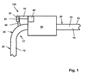
- FIG. 1 An embodiment of a device 100 according to the invention is shown schematically in FIG FIG. 1 shown.
- the device 100 according to the invention shown there has, as essential components, a digital camera 30, which is rigidly connected to a vehicle 10 via an arm 16, and a computing device 40.
- the computing device 40 may also be integrated into the digital camera 30.
- the vehicle 10 which may, for example, be a monorail monorail, moves on rollers (not shown here) on a support 14, through which a web 12 is provided.
- the digital camera 30 is positioned such that at least one marker 20 in each case falls into the detection area 32 of the digital camera 30.
- An essential idea of the Invention is that of the digital camera 30 in its detection range 32, see FIG. 2 to evaluate recorded optical information as part of an image processing.
- the positions of the marker images in the detection area 32 are evaluated.
- a special feature of the invention which in the in FIG. 1 shown situation, where the vehicle 10 moves through a curved area 17, comes into play, is that in addition to the location or position of the marker images in the detection area 32 of the digital camera 30 and the shape of the marker images considered and evaluated.
- From the position and shape of the marker images can then be calculated back to the relative position and orientation of the digital camera 30 relative to the marker in question and it can thus the precise positioning of the vehicle 10 with respect to the web 12 are calculated.
- the computer program according to the invention is processed in the computer 40 present in accordance with the invention.
- a computer program product in the sense of the invention may in particular be the computing device 40 itself with associated ROM memory.
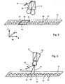
- FIGS. 2 and 3 Schematic partial views of this basic situation can also be found in the FIGS. 2 and 3 where each camera is shown in an untilted position, reference numeral 31, and in a tilted position, reference numeral 30.
- the tilt angle is in FIGS. 2 and 3 each the same.
- the markers 20 on the web 12 are shown there.
- the markers are glued onto the web 12 as a code tape 19.
- a detection area 32 of the tilted digital camera 30 is shown schematically, wherein a marker 22 completely falls within this detection area 32 and the adjacent markers 21, 23 are each detected halfway from the detection area 32.
- the situation of a camera tilted in relation to the track 12 can also occur if the camera can not be installed orthogonally to the track for technical reasons or if it makes sense for other reasons to select a tilted installation method.
- an assumed rotation axis 52 is located at a rear end of the digital camera 30, whereas in FIG. 3 an assumed one Rotation axis 54 at the front end, ie in the region of the lens of the digital camera 30, is rotated.
- the location of the spatial axes for the FIGS. 2 and 3 is indicated in a coordinate system 90.
- An essential idea of the invention is that with known distance of the pivot point in the FIGS. 2 and 3 is represented as a rotation axis 52 or rotation axis 54, from the web 12, that is, from the reading surface, from a picture taken by the digital camera 30, a position of the pivot point projected perpendicular to the web is calculated.
- the reference numeral 60 denotes an optical axis of the camera 30 and the point of impact of this optical axis 60 on the web 12 between the markers 24 and 25 substantially corresponds to the position which would be obtained if the tilt were not determined and based thereon would reckon on the vertical projection on the web 12.
- a position of the vehicle 10 can be determined virtually independent of the specific arrangement of the digital camera 30 on the vehicle 10. It is only important that one knows the concrete geometry of the arrangement of the digital camera 30 on the vehicle 10 and can accordingly make available as parameters of the arithmetic unit 40. This results in the application of the significant advantage of a considerably simplified adjustment of the camera. In addition, a tilting of the camera during operation does not entail a change in position. For example, process variants are possible in which the distance of the pivot point to the web 12 or the code band 19 is the only parameter to be set.
- a distance of the center of the image to the code band 19, ie to the plane in which the markers 20 are arranged, is first recorded on the basis of the image recorded by the digital camera 30.
- the size of a marker image is inversely proportional to the distance from the respective marker.
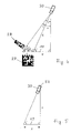
- FIG. 4 shows FIG. 4 also schematically a two-dimensional barcode 27 and a distorted image 28 of this barcode, as shown in the in FIG. 4 shown situation, the digital camera 30 due to the tilt, which in FIG. 4 is marked with an angle ⁇ , is detected.
- a distance E of the front edge from the digital camera 30 is first calculated from the size of the marker image. Furthermore, a width ⁇ of the imaged barcode 28 is also determined from the size of the marker image. Given is an original width ⁇ of the corresponding barcode 27. This corresponds essentially to an edge length of the barcode 27th
- the invention is therefore based on the fact that based on the distance E and a tilt angle ⁇ , the distance X, as shown above, can be calculated.
- the distance X in the case of Figure 5 is the fulcrum 52 of the digital camera 30 at the end of the camera body.
- the pivot point can also be at a different location of the digital camera 30 or completely outside the camera housing.
- the above detailed calculation for this variant of the method essentially requires elementary trigonometric calculations.
- the position offset X is then added to the read position of the image center, resulting in, as desired, a real position of the fulcrum 52 orthogonal over the code band 19.
- a new method and a new device for determining the position of vehicles are given, with which significantly longer routes are possible and beyond the position in curves can be precisely detected.
- the positioning accuracy for vehicles is accordingly improved and the output position information can be linearized.
Landscapes
- Engineering & Computer Science (AREA)
- Physics & Mathematics (AREA)
- General Physics & Mathematics (AREA)
- Mechanical Engineering (AREA)
- Automation & Control Theory (AREA)
- Electromagnetism (AREA)
- Aviation & Aerospace Engineering (AREA)
- Radar, Positioning & Navigation (AREA)
- Remote Sensing (AREA)
- Length Measuring Devices By Optical Means (AREA)
- Image Analysis (AREA)
Applications Claiming Priority (2)
| Application Number | Priority Date | Filing Date | Title |
|---|---|---|---|
| DE200720012798 DE202007012798U1 (de) | 2007-09-12 | 2007-09-12 | Positioniersysteme |
| DE102007043498A DE102007043498A1 (de) | 2007-09-12 | 2007-09-12 | Verfahren zur Positionierung eines Fahrzeugs sowie Positioniersysteme |
Publications (2)
| Publication Number | Publication Date |
|---|---|
| EP2037227A1 true EP2037227A1 (fr) | 2009-03-18 |
| EP2037227B1 EP2037227B1 (fr) | 2015-11-04 |
Family
ID=39670412
Family Applications (6)
| Application Number | Title | Priority Date | Filing Date |
|---|---|---|---|
| EP08005213.7A Active EP2037226B1 (fr) | 2007-09-12 | 2008-03-19 | Procédé et dispositif destinés à la détermination de la position d`un véhicule, programme informatique et produit de programme informatique |
| EP08005214.5A Active EP2037224B1 (fr) | 2007-09-12 | 2008-03-19 | Procédé et dispositif destinés à la détermination de la position d'un véhicule, programme informatique et produit de programme informatique |
| EP08005216A Active EP2037225B1 (fr) | 2007-09-12 | 2008-03-19 | Procédé et dispositif destinés à la détermination de la position d'un véhicule, programme informatique et produit de programme informatique |
| EP08005215.2A Active EP2037227B1 (fr) | 2007-09-12 | 2008-03-19 | Procédé et dispositif destinés à la détermination de la position d'un véhicule |
| EP08005217.8A Active EP2037228B1 (fr) | 2007-09-12 | 2008-03-19 | Procédé et dispositif destinés à la détermination d'un intervalle de maintenance d'un véhicule, programme informatique et produit de programme informatique |
| EP08005218A Withdrawn EP2037229A1 (fr) | 2007-09-12 | 2008-03-19 | Procédé et dispositif pour déterminer la position d'un véhicule |
Family Applications Before (3)
| Application Number | Title | Priority Date | Filing Date |
|---|---|---|---|
| EP08005213.7A Active EP2037226B1 (fr) | 2007-09-12 | 2008-03-19 | Procédé et dispositif destinés à la détermination de la position d`un véhicule, programme informatique et produit de programme informatique |
| EP08005214.5A Active EP2037224B1 (fr) | 2007-09-12 | 2008-03-19 | Procédé et dispositif destinés à la détermination de la position d'un véhicule, programme informatique et produit de programme informatique |
| EP08005216A Active EP2037225B1 (fr) | 2007-09-12 | 2008-03-19 | Procédé et dispositif destinés à la détermination de la position d'un véhicule, programme informatique et produit de programme informatique |
Family Applications After (2)
| Application Number | Title | Priority Date | Filing Date |
|---|---|---|---|
| EP08005217.8A Active EP2037228B1 (fr) | 2007-09-12 | 2008-03-19 | Procédé et dispositif destinés à la détermination d'un intervalle de maintenance d'un véhicule, programme informatique et produit de programme informatique |
| EP08005218A Withdrawn EP2037229A1 (fr) | 2007-09-12 | 2008-03-19 | Procédé et dispositif pour déterminer la position d'un véhicule |
Country Status (3)
| Country | Link |
|---|---|
| EP (6) | EP2037226B1 (fr) |
| AT (1) | ATE522788T1 (fr) |
| ES (4) | ES2564810T3 (fr) |
Cited By (3)
| Publication number | Priority date | Publication date | Assignee | Title |
|---|---|---|---|---|
| US9354070B2 (en) | 2013-10-31 | 2016-05-31 | Crown Equipment Corporation | Systems, methods, and industrial vehicles for determining the visibility of features |
| WO2021032314A1 (fr) * | 2019-08-19 | 2021-02-25 | Sew-Eurodrive Gmbh & Co. Kg | Procédé pour faire fonctionner un système comprenant des première et deuxième parties mobiles et comprenant un contrôleur fixe, et système de mise en œuvre d'un procédé |
| EP3680624B1 (fr) | 2019-01-11 | 2022-09-07 | Leuze electronic GmbH + Co. KG | Dispositif de détection |
Families Citing this family (15)
| Publication number | Priority date | Publication date | Assignee | Title |
|---|---|---|---|---|
| DE102010008957A1 (de) * | 2010-02-19 | 2011-08-25 | FusionSystems GmbH, 09125 | Positionsbestimmung mittels optischer Kode-Schiene (Astropos) |
| DE102012010677B4 (de) * | 2012-05-31 | 2021-10-21 | Pentanova Cs Gmbh | Verfahren zum Betreiben einer Förderanlage |
| CN103197679B (zh) * | 2013-03-22 | 2016-01-06 | 长沙理工大学 | 一种轨道式巡检机器人的精确定位方法 |
| DE102013226201A1 (de) * | 2013-12-17 | 2015-06-18 | Robert Bosch Gmbh | Linearführung mit kombinierter Last- und Positionsmessung |
| ES2705084T3 (es) | 2014-03-21 | 2019-03-21 | Liebherr Components Biberach | Dispositivo para la determinación del estado de desgaste de un cable al emplearlo en equipos elevadores |
| CU20180096A7 (es) * | 2016-03-02 | 2018-11-06 | Auto Drive Solutions Sl | Medios de información codificada situados en una infraestructura para ser decodificados por sensores situados sobre móviles |
| CN107934782A (zh) * | 2017-10-24 | 2018-04-20 | 安徽德马泰格起重机械有限公司 | 一种行车自动刹停控制系统 |
| US11341342B2 (en) * | 2018-02-14 | 2022-05-24 | Aeolus Robotics Corporation Limited | Optical encoder and method of operating the same |
| CN108803603B (zh) * | 2018-06-05 | 2021-11-30 | 广州市远能物流自动化设备科技有限公司 | 基于编码图像的agv小车对接定位方法及agv小车 |
| CN110217689A (zh) * | 2019-07-02 | 2019-09-10 | 明兴富 | 无线充电塔吊吊钩可视化系统 |
| CN110304115B (zh) * | 2019-07-30 | 2024-02-20 | 东莞开道科技有限公司 | 基于色彩编码的移动定位装置、方法及轨道交通系统 |
| EP4013661B1 (fr) | 2019-08-13 | 2023-09-06 | Sew-Eurodrive GmbH & Co. KG | Système, en particulier installation, comprenant une partie mobile pouvant se déplacer le long d'une région de codage, et procédé de fonctionnement d'un tel système |
| EP3851806B1 (fr) * | 2020-01-15 | 2023-01-11 | Leuze electronic GmbH + Co. KG | Dispositif capteur et procédé de fonctionnement d'un dispositif capteur |
| DE202021105265U1 (de) | 2021-09-29 | 2023-01-10 | Leuze Electronic Gmbh + Co. Kg | Sensoranordnung |
| CN117566600B (zh) * | 2024-01-16 | 2024-03-29 | 山东鑫鹏宇矿业装备有限公司 | 一种基于物联网的矿用单轨吊安全运行控制系统 |
Citations (11)
| Publication number | Priority date | Publication date | Assignee | Title |
|---|---|---|---|---|
| EP0039921A2 (fr) | 1980-05-12 | 1981-11-18 | Tokyo Kogaku Kikai Kabushiki Kaisha | Dispositif codeur et méthode pour son utilisation |
| EP0116636A1 (fr) | 1982-09-01 | 1984-08-29 | Rosemount Eng Co Ltd | Dispositif de mesure de position. |
| DE3825097A1 (de) | 1988-07-23 | 1990-02-08 | Stahl R Foerdertech Gmbh | Vorrichtung zur positionsmessung bei kran- und elektrohaengebahnen |
| DE3910873A1 (de) | 1989-04-04 | 1990-10-18 | Stahl R Foerdertech Gmbh | Positionsmessvorrichtung fuer kran- und elektrohaengebahnen |
| DE4104602C1 (fr) * | 1991-02-12 | 1992-06-04 | E.M.S. Technik Gmbh, 2950 Leer, De | |
| DE4209629A1 (de) | 1991-03-25 | 1992-10-01 | Nikon Corp | Absolutkodierer |
| DE4309863C1 (de) | 1993-03-26 | 1994-06-09 | Stahl R Foerdertech Gmbh | Positionsmeßeinrichtung sowie Verfahren zum Ablesen eines binären Codewortes |
| EP0722903A1 (fr) * | 1995-01-20 | 1996-07-24 | Inventio Ag | Méthode et dispositif pour générer de l'information de cage d'une cage d'ascenseur |
| DE19910933A1 (de) | 1999-03-12 | 2000-09-21 | Leuze Electronic Gmbh & Co | Vorrichtung zur Positionierung eines Fahrzeugs |
| EP1582846A2 (fr) * | 2004-03-31 | 2005-10-05 | Mitutoyo Corporation | Échelle pour un système de mesure de translation et d'orientation |
| DE102004018404A1 (de) * | 2004-04-16 | 2005-11-03 | Leuze Electronic Gmbh & Co Kg | Optoelektronische Vorrichtung |
Family Cites Families (22)
| Publication number | Priority date | Publication date | Assignee | Title |
|---|---|---|---|---|
| US3842923A (en) * | 1973-11-15 | 1974-10-22 | Nat Controls | Overhead track scale |
| US4363369A (en) * | 1981-02-02 | 1982-12-14 | Masstron Scale Inc. | Overhead track scale |
| DE3150977A1 (de) * | 1981-12-23 | 1983-06-30 | Fa. Carl Zeiss, 7920 Heidenheim | Verfahren und einrichtung zur ermittlung und korrektur von fuehrungsfehlern |
| DE4038972C1 (fr) * | 1990-12-06 | 1991-11-07 | Man Nutzfahrzeuge Ag, 8000 Muenchen, De | |
| US20020044689A1 (en) * | 1992-10-02 | 2002-04-18 | Alex Roustaei | Apparatus and method for global and local feature extraction from digital images |
| US5332180A (en) * | 1992-12-28 | 1994-07-26 | Union Switch & Signal Inc. | Traffic control system utilizing on-board vehicle information measurement apparatus |
| DE19532104C1 (de) * | 1995-08-30 | 1997-01-16 | Daimler Benz Ag | Verfahren und Vorrichtung zur Bestimmung der Position wenigstens einer Stelle eines spurgeführten Fahrzeugs |
| IT1287818B1 (it) | 1996-08-01 | 1998-08-19 | Tecma Srl | Sistema di orientamento e guida per veicoli semoventi, e relativa apparecchiatura |
| DE19709445B4 (de) * | 1997-03-07 | 2004-01-15 | Volkswagen Ag | Vorrichtung und Verfahren zur Berechnung und Anzeige von Service-Intervallen |
| US5965879A (en) * | 1997-05-07 | 1999-10-12 | The United States Of America As Represented By The Administrator Of The National Aeronautics And Space Administration | Method and apparatus for ultra-high-sensitivity, incremental and absolute optical encoding |
| EP1075996A1 (fr) * | 1999-07-13 | 2001-02-14 | Tiefenbach GmbH | Procédé de localisation de véhicules dans un réseau de voies ferroviaires et véhicule ferroviaire |
| US7783507B2 (en) * | 1999-08-23 | 2010-08-24 | General Electric Company | System and method for managing a fleet of remote assets |
| GB9926574D0 (en) * | 1999-11-11 | 2000-01-12 | Renishaw Plc | Absolute position measurement |
| US20060244830A1 (en) * | 2002-06-04 | 2006-11-02 | Davenport David M | System and method of navigation with captured images |
| DE50209363D1 (de) * | 2002-11-07 | 2007-03-15 | Siemens Schweiz Ag | Verfahren zur Lage- und Geschwindigkeitsbestimmung |
| US6757434B2 (en) * | 2002-11-12 | 2004-06-29 | Nokia Corporation | Region-of-interest tracking method and device for wavelet-based video coding |
| US6867412B2 (en) * | 2002-11-12 | 2005-03-15 | Mitutoyo Corporation | Scale structures and methods usable in an absolute position transducer |
| DE10313036B3 (de) * | 2003-03-24 | 2004-08-19 | Klingelnberg Gmbh | Vorrichtung zum Erfassen der räumlichen Lage eines in einer Koordinatenachse verfahrbaren Schlittens |
| DE10341297B3 (de) * | 2003-09-04 | 2005-07-07 | Dorma Gmbh + Co. Kg | Codierte Absolutpositions-Messung für in Schienen geführte Elemente |
| WO2006065563A2 (fr) * | 2004-12-14 | 2006-06-22 | Sky-Trax Incorporated | Procede et appareil de determination de la position et l'orientation rotative d'un objet |
| GB0602448D0 (en) * | 2006-02-07 | 2006-03-22 | Shenton Richard | System For Train Speed, Position And Integrity Measurement |
| DE102006010161B4 (de) * | 2006-02-28 | 2010-04-08 | Dr. Johannes Heidenhain Gmbh | Codestruktur für eine Positionsmesseinrichtung und Positionsmesseinrichtung mit einer solchen Codestruktur |
-
2008
- 2008-03-19 ES ES08005213.7T patent/ES2564810T3/es active Active
- 2008-03-19 EP EP08005213.7A patent/EP2037226B1/fr active Active
- 2008-03-19 EP EP08005214.5A patent/EP2037224B1/fr active Active
- 2008-03-19 EP EP08005216A patent/EP2037225B1/fr active Active
- 2008-03-19 EP EP08005215.2A patent/EP2037227B1/fr active Active
- 2008-03-19 EP EP08005217.8A patent/EP2037228B1/fr active Active
- 2008-03-19 ES ES08005214.5T patent/ES2556174T3/es active Active
- 2008-03-19 ES ES08005217.8T patent/ES2558801T3/es active Active
- 2008-03-19 AT AT08005216T patent/ATE522788T1/de active
- 2008-03-19 EP EP08005218A patent/EP2037229A1/fr not_active Withdrawn
- 2008-03-19 ES ES08005215.2T patent/ES2558022T3/es active Active
Patent Citations (11)
| Publication number | Priority date | Publication date | Assignee | Title |
|---|---|---|---|---|
| EP0039921A2 (fr) | 1980-05-12 | 1981-11-18 | Tokyo Kogaku Kikai Kabushiki Kaisha | Dispositif codeur et méthode pour son utilisation |
| EP0116636A1 (fr) | 1982-09-01 | 1984-08-29 | Rosemount Eng Co Ltd | Dispositif de mesure de position. |
| DE3825097A1 (de) | 1988-07-23 | 1990-02-08 | Stahl R Foerdertech Gmbh | Vorrichtung zur positionsmessung bei kran- und elektrohaengebahnen |
| DE3910873A1 (de) | 1989-04-04 | 1990-10-18 | Stahl R Foerdertech Gmbh | Positionsmessvorrichtung fuer kran- und elektrohaengebahnen |
| DE4104602C1 (fr) * | 1991-02-12 | 1992-06-04 | E.M.S. Technik Gmbh, 2950 Leer, De | |
| DE4209629A1 (de) | 1991-03-25 | 1992-10-01 | Nikon Corp | Absolutkodierer |
| DE4309863C1 (de) | 1993-03-26 | 1994-06-09 | Stahl R Foerdertech Gmbh | Positionsmeßeinrichtung sowie Verfahren zum Ablesen eines binären Codewortes |
| EP0722903A1 (fr) * | 1995-01-20 | 1996-07-24 | Inventio Ag | Méthode et dispositif pour générer de l'information de cage d'une cage d'ascenseur |
| DE19910933A1 (de) | 1999-03-12 | 2000-09-21 | Leuze Electronic Gmbh & Co | Vorrichtung zur Positionierung eines Fahrzeugs |
| EP1582846A2 (fr) * | 2004-03-31 | 2005-10-05 | Mitutoyo Corporation | Échelle pour un système de mesure de translation et d'orientation |
| DE102004018404A1 (de) * | 2004-04-16 | 2005-11-03 | Leuze Electronic Gmbh & Co Kg | Optoelektronische Vorrichtung |
Cited By (3)
| Publication number | Priority date | Publication date | Assignee | Title |
|---|---|---|---|---|
| US9354070B2 (en) | 2013-10-31 | 2016-05-31 | Crown Equipment Corporation | Systems, methods, and industrial vehicles for determining the visibility of features |
| EP3680624B1 (fr) | 2019-01-11 | 2022-09-07 | Leuze electronic GmbH + Co. KG | Dispositif de détection |
| WO2021032314A1 (fr) * | 2019-08-19 | 2021-02-25 | Sew-Eurodrive Gmbh & Co. Kg | Procédé pour faire fonctionner un système comprenant des première et deuxième parties mobiles et comprenant un contrôleur fixe, et système de mise en œuvre d'un procédé |
Also Published As
| Publication number | Publication date |
|---|---|
| EP2037224B1 (fr) | 2015-10-14 |
| EP2037224A1 (fr) | 2009-03-18 |
| ES2558022T3 (es) | 2016-02-01 |
| ES2564810T3 (es) | 2016-03-29 |
| EP2037225A1 (fr) | 2009-03-18 |
| ES2556174T3 (es) | 2016-01-13 |
| ATE522788T1 (de) | 2011-09-15 |
| EP2037226A2 (fr) | 2009-03-18 |
| EP2037225B1 (fr) | 2011-08-31 |
| EP2037226B1 (fr) | 2016-02-17 |
| ES2558801T3 (es) | 2016-02-08 |
| EP2037226A3 (fr) | 2009-08-12 |
| EP2037227B1 (fr) | 2015-11-04 |
| EP2037229A1 (fr) | 2009-03-18 |
| EP2037228B1 (fr) | 2015-11-11 |
| EP2037228A1 (fr) | 2009-03-18 |
Similar Documents
| Publication | Publication Date | Title |
|---|---|---|
| EP2037227B1 (fr) | Procédé et dispositif destinés à la détermination de la position d'un véhicule | |
| AT518839B1 (de) | System und Verfahren zum Vermessen eines Gleises | |
| WO2012110343A1 (fr) | Procédé de localisation autonome d'un véhicule motorisé sans conducteur | |
| DE112012003040T5 (de) | Fahrspurerkennungsvorrichtung | |
| EP2728305A1 (fr) | Procédé, dispositif et modèle lumineux pour mesurer la hauteur ou le trajet en hauteur d'un objet | |
| WO2009043789A1 (fr) | Procédé de calibrage d'un dispositif de détection et dispositif de détection | |
| EP3316181A1 (fr) | Procédé de détection d'objets dans un entrepôt et chariot élévateur doté d'un dispositif de détection d'objets dans un entrepôt | |
| DE102018121481A1 (de) | Entfernungsmesssystem und Entfernungsmessverfahren | |
| EP2356400B1 (fr) | Robot de mesure tridimensionnelle automatique et procédé associé | |
| DE10161060B4 (de) | Fehlerprüfverfahren für einen dreidimensionalen Gegenstand | |
| EP2865988B1 (fr) | Capteur de profil optique | |
| DE10312535B4 (de) | Verfahren und Vorrichtung zum geometrischen Vermessen eines Materialbandes | |
| EP2208168A2 (fr) | Procédé et système pour détecter le profil d'une voie | |
| WO2012160056A1 (fr) | Dispositif et procédé permettant de mesurer le train de roulement d'un véhicule automobile | |
| DE102019209861A1 (de) | System und Verfahren zur Visualisierung von Oberflächendefekten auf einem Werkstück | |
| DE102008032786A1 (de) | Vorrichtung und Verfahren zum Bestimmen einer Position eines Fahrzeugs | |
| DE102007056773B4 (de) | Verfahren zum automatischen Bestimmen eines virtuellen Arbeitspunktes | |
| EP3655175B1 (fr) | Procédé de fonctionnement d'une installation d'usinage équipée d'un piston mobile | |
| DE102017122627B4 (de) | Optisches Messsystem und Messverfahren | |
| WO2019206625A1 (fr) | Système de localisation et procédé permettant de déterminer une position actuelle dans une cage d'ascenseur d'une installation d'ascenseur | |
| DE10128722C1 (de) | Vorrichtung zur Kontrolle von Objekten | |
| DE102006015036A1 (de) | Verfahren zur Fahrwegüberwachung | |
| DE102019102783A1 (de) | Ausrichtziel und Verfahren zum Ausrichten einer Kamera | |
| DE10230614B3 (de) | Anordnung von Referenzmarken auf Messrasterplatten und von Referenzmarkensensoren auf einem dazugehörigen optoelektronisch arbeitenden Messkopf | |
| DE102022119355A1 (de) | Fahrerloses Transportsystem |
Legal Events
| Date | Code | Title | Description |
|---|---|---|---|
| PUAI | Public reference made under article 153(3) epc to a published international application that has entered the european phase |
Free format text: ORIGINAL CODE: 0009012 |
|
| AK | Designated contracting states |
Kind code of ref document: A1 Designated state(s): AT BE BG CH CY CZ DE DK EE ES FI FR GB GR HR HU IE IS IT LI LT LU LV MC MT NL NO PL PT RO SE SI SK TR |
|
| AX | Request for extension of the european patent |
Extension state: AL BA MK RS |
|
| 17P | Request for examination filed |
Effective date: 20090916 |
|
| 17Q | First examination report despatched |
Effective date: 20091016 |
|
| AKX | Designation fees paid |
Designated state(s): AT BE BG CH CY CZ DE DK EE ES FI FR GB GR HR HU IE IS IT LI LT LU LV MC MT NL NO PL PT RO SE SI SK TR |
|
| REG | Reference to a national code |
Ref country code: DE Ref legal event code: R079 Ref document number: 502008013535 Country of ref document: DE Free format text: PREVIOUS MAIN CLASS: G01D0005347000 Ipc: B61L0025020000 |
|
| GRAP | Despatch of communication of intention to grant a patent |
Free format text: ORIGINAL CODE: EPIDOSNIGR1 |
|
| RIC1 | Information provided on ipc code assigned before grant |
Ipc: G01D 5/26 20060101ALI20150520BHEP Ipc: G01D 5/347 20060101ALI20150520BHEP Ipc: B66C 13/16 20060101ALI20150520BHEP Ipc: G05D 1/02 20060101ALI20150520BHEP Ipc: B66C 13/46 20060101ALI20150520BHEP Ipc: B61L 25/02 20060101AFI20150520BHEP Ipc: G01D 5/249 20060101ALI20150520BHEP |
|
| INTG | Intention to grant announced |
Effective date: 20150612 |
|
| RAP1 | Party data changed (applicant data changed or rights of an application transferred) |
Owner name: PEPPERL + FUCHS GMBH |
|
| GRAS | Grant fee paid |
Free format text: ORIGINAL CODE: EPIDOSNIGR3 |
|
| GRAA | (expected) grant |
Free format text: ORIGINAL CODE: 0009210 |
|
| AK | Designated contracting states |
Kind code of ref document: B1 Designated state(s): AT BE BG CH CY CZ DE DK EE ES FI FR GB GR HR HU IE IS IT LI LT LU LV MC MT NL NO PL PT RO SE SI SK TR |
|
| REG | Reference to a national code |
Ref country code: GB Ref legal event code: FG4D Free format text: NOT ENGLISH |
|
| REG | Reference to a national code |
Ref country code: CH Ref legal event code: EP |
|
| REG | Reference to a national code |
Ref country code: AT Ref legal event code: REF Ref document number: 758963 Country of ref document: AT Kind code of ref document: T Effective date: 20151115 |
|
| REG | Reference to a national code |
Ref country code: IE Ref legal event code: FG4D Free format text: LANGUAGE OF EP DOCUMENT: GERMAN |
|
| REG | Reference to a national code |
Ref country code: DE Ref legal event code: R096 Ref document number: 502008013535 Country of ref document: DE |
|
| REG | Reference to a national code |
Ref country code: CH Ref legal event code: NV Representative=s name: ISLER AND PEDRAZZINI AG, CH |
|
| REG | Reference to a national code |
Ref country code: ES Ref legal event code: FG2A Ref document number: 2558022 Country of ref document: ES Kind code of ref document: T3 Effective date: 20160201 |
|
| REG | Reference to a national code |
Ref country code: NL Ref legal event code: MP Effective date: 20151104 |
|
| REG | Reference to a national code |
Ref country code: LT Ref legal event code: MG4D |
|
| REG | Reference to a national code |
Ref country code: FR Ref legal event code: PLFP Year of fee payment: 9 |
|
| PG25 | Lapsed in a contracting state [announced via postgrant information from national office to epo] |
Ref country code: NL Free format text: LAPSE BECAUSE OF FAILURE TO SUBMIT A TRANSLATION OF THE DESCRIPTION OR TO PAY THE FEE WITHIN THE PRESCRIBED TIME-LIMIT Effective date: 20151104 Ref country code: HR Free format text: LAPSE BECAUSE OF FAILURE TO SUBMIT A TRANSLATION OF THE DESCRIPTION OR TO PAY THE FEE WITHIN THE PRESCRIBED TIME-LIMIT Effective date: 20151104 Ref country code: IS Free format text: LAPSE BECAUSE OF FAILURE TO SUBMIT A TRANSLATION OF THE DESCRIPTION OR TO PAY THE FEE WITHIN THE PRESCRIBED TIME-LIMIT Effective date: 20160304 Ref country code: LT Free format text: LAPSE BECAUSE OF FAILURE TO SUBMIT A TRANSLATION OF THE DESCRIPTION OR TO PAY THE FEE WITHIN THE PRESCRIBED TIME-LIMIT Effective date: 20151104 Ref country code: NO Free format text: LAPSE BECAUSE OF FAILURE TO SUBMIT A TRANSLATION OF THE DESCRIPTION OR TO PAY THE FEE WITHIN THE PRESCRIBED TIME-LIMIT Effective date: 20160204 |
|
| PG25 | Lapsed in a contracting state [announced via postgrant information from national office to epo] |
Ref country code: PT Free format text: LAPSE BECAUSE OF FAILURE TO SUBMIT A TRANSLATION OF THE DESCRIPTION OR TO PAY THE FEE WITHIN THE PRESCRIBED TIME-LIMIT Effective date: 20160304 Ref country code: SE Free format text: LAPSE BECAUSE OF FAILURE TO SUBMIT A TRANSLATION OF THE DESCRIPTION OR TO PAY THE FEE WITHIN THE PRESCRIBED TIME-LIMIT Effective date: 20151104 Ref country code: GR Free format text: LAPSE BECAUSE OF FAILURE TO SUBMIT A TRANSLATION OF THE DESCRIPTION OR TO PAY THE FEE WITHIN THE PRESCRIBED TIME-LIMIT Effective date: 20160205 Ref country code: LV Free format text: LAPSE BECAUSE OF FAILURE TO SUBMIT A TRANSLATION OF THE DESCRIPTION OR TO PAY THE FEE WITHIN THE PRESCRIBED TIME-LIMIT Effective date: 20151104 Ref country code: PL Free format text: LAPSE BECAUSE OF FAILURE TO SUBMIT A TRANSLATION OF THE DESCRIPTION OR TO PAY THE FEE WITHIN THE PRESCRIBED TIME-LIMIT Effective date: 20151104 Ref country code: FI Free format text: LAPSE BECAUSE OF FAILURE TO SUBMIT A TRANSLATION OF THE DESCRIPTION OR TO PAY THE FEE WITHIN THE PRESCRIBED TIME-LIMIT Effective date: 20151104 |
|
| PG25 | Lapsed in a contracting state [announced via postgrant information from national office to epo] |
Ref country code: CZ Free format text: LAPSE BECAUSE OF FAILURE TO SUBMIT A TRANSLATION OF THE DESCRIPTION OR TO PAY THE FEE WITHIN THE PRESCRIBED TIME-LIMIT Effective date: 20151104 |
|
| REG | Reference to a national code |
Ref country code: DE Ref legal event code: R097 Ref document number: 502008013535 Country of ref document: DE |
|
| PG25 | Lapsed in a contracting state [announced via postgrant information from national office to epo] |
Ref country code: BE Free format text: LAPSE BECAUSE OF NON-PAYMENT OF DUE FEES Effective date: 20160331 Ref country code: RO Free format text: LAPSE BECAUSE OF FAILURE TO SUBMIT A TRANSLATION OF THE DESCRIPTION OR TO PAY THE FEE WITHIN THE PRESCRIBED TIME-LIMIT Effective date: 20151104 Ref country code: EE Free format text: LAPSE BECAUSE OF FAILURE TO SUBMIT A TRANSLATION OF THE DESCRIPTION OR TO PAY THE FEE WITHIN THE PRESCRIBED TIME-LIMIT Effective date: 20151104 Ref country code: SK Free format text: LAPSE BECAUSE OF FAILURE TO SUBMIT A TRANSLATION OF THE DESCRIPTION OR TO PAY THE FEE WITHIN THE PRESCRIBED TIME-LIMIT Effective date: 20151104 Ref country code: DK Free format text: LAPSE BECAUSE OF FAILURE TO SUBMIT A TRANSLATION OF THE DESCRIPTION OR TO PAY THE FEE WITHIN THE PRESCRIBED TIME-LIMIT Effective date: 20151104 |
|
| PLBE | No opposition filed within time limit |
Free format text: ORIGINAL CODE: 0009261 |
|
| STAA | Information on the status of an ep patent application or granted ep patent |
Free format text: STATUS: NO OPPOSITION FILED WITHIN TIME LIMIT |
|
| 26N | No opposition filed |
Effective date: 20160805 |
|
| PG25 | Lapsed in a contracting state [announced via postgrant information from national office to epo] |
Ref country code: MC Free format text: LAPSE BECAUSE OF FAILURE TO SUBMIT A TRANSLATION OF THE DESCRIPTION OR TO PAY THE FEE WITHIN THE PRESCRIBED TIME-LIMIT Effective date: 20151104 Ref country code: LU Free format text: LAPSE BECAUSE OF FAILURE TO SUBMIT A TRANSLATION OF THE DESCRIPTION OR TO PAY THE FEE WITHIN THE PRESCRIBED TIME-LIMIT Effective date: 20160319 |
|
| PG25 | Lapsed in a contracting state [announced via postgrant information from national office to epo] |
Ref country code: SI Free format text: LAPSE BECAUSE OF FAILURE TO SUBMIT A TRANSLATION OF THE DESCRIPTION OR TO PAY THE FEE WITHIN THE PRESCRIBED TIME-LIMIT Effective date: 20151104 |
|
| REG | Reference to a national code |
Ref country code: IE Ref legal event code: MM4A |
|
| PG25 | Lapsed in a contracting state [announced via postgrant information from national office to epo] |
Ref country code: IE Free format text: LAPSE BECAUSE OF NON-PAYMENT OF DUE FEES Effective date: 20160319 |
|
| REG | Reference to a national code |
Ref country code: FR Ref legal event code: PLFP Year of fee payment: 10 |
|
| PG25 | Lapsed in a contracting state [announced via postgrant information from national office to epo] |
Ref country code: MT Free format text: LAPSE BECAUSE OF FAILURE TO SUBMIT A TRANSLATION OF THE DESCRIPTION OR TO PAY THE FEE WITHIN THE PRESCRIBED TIME-LIMIT Effective date: 20151104 |
|
| REG | Reference to a national code |
Ref country code: FR Ref legal event code: PLFP Year of fee payment: 11 |
|
| PGFP | Annual fee paid to national office [announced via postgrant information from national office to epo] |
Ref country code: GB Payment date: 20180321 Year of fee payment: 11 |
|
| PG25 | Lapsed in a contracting state [announced via postgrant information from national office to epo] |
Ref country code: HU Free format text: LAPSE BECAUSE OF FAILURE TO SUBMIT A TRANSLATION OF THE DESCRIPTION OR TO PAY THE FEE WITHIN THE PRESCRIBED TIME-LIMIT; INVALID AB INITIO Effective date: 20080319 Ref country code: CY Free format text: LAPSE BECAUSE OF FAILURE TO SUBMIT A TRANSLATION OF THE DESCRIPTION OR TO PAY THE FEE WITHIN THE PRESCRIBED TIME-LIMIT Effective date: 20151104 |
|
| PGFP | Annual fee paid to national office [announced via postgrant information from national office to epo] |
Ref country code: AT Payment date: 20180322 Year of fee payment: 11 Ref country code: FR Payment date: 20180330 Year of fee payment: 11 |
|
| REG | Reference to a national code |
Ref country code: DE Ref legal event code: R082 Ref document number: 502008013535 Country of ref document: DE Representative=s name: SCHIFFER, AXEL, DIPL.-PHYS.UNIV. DR.RER.NAT., DE |
|
| PG25 | Lapsed in a contracting state [announced via postgrant information from national office to epo] |
Ref country code: TR Free format text: LAPSE BECAUSE OF FAILURE TO SUBMIT A TRANSLATION OF THE DESCRIPTION OR TO PAY THE FEE WITHIN THE PRESCRIBED TIME-LIMIT Effective date: 20151104 |
|
| PG25 | Lapsed in a contracting state [announced via postgrant information from national office to epo] |
Ref country code: BG Free format text: LAPSE BECAUSE OF FAILURE TO SUBMIT A TRANSLATION OF THE DESCRIPTION OR TO PAY THE FEE WITHIN THE PRESCRIBED TIME-LIMIT Effective date: 20151104 |
|
| PGFP | Annual fee paid to national office [announced via postgrant information from national office to epo] |
Ref country code: ES Payment date: 20180430 Year of fee payment: 11 |
|
| PGFP | Annual fee paid to national office [announced via postgrant information from national office to epo] |
Ref country code: IT Payment date: 20180327 Year of fee payment: 11 |
|
| REG | Reference to a national code |
Ref country code: CH Ref legal event code: PL |
|
| REG | Reference to a national code |
Ref country code: AT Ref legal event code: MM01 Ref document number: 758963 Country of ref document: AT Kind code of ref document: T Effective date: 20190319 |
|
| GBPC | Gb: european patent ceased through non-payment of renewal fee |
Effective date: 20190319 |
|
| PG25 | Lapsed in a contracting state [announced via postgrant information from national office to epo] |
Ref country code: GB Free format text: LAPSE BECAUSE OF NON-PAYMENT OF DUE FEES Effective date: 20190319 Ref country code: CH Free format text: LAPSE BECAUSE OF NON-PAYMENT OF DUE FEES Effective date: 20190331 Ref country code: LI Free format text: LAPSE BECAUSE OF NON-PAYMENT OF DUE FEES Effective date: 20190331 Ref country code: AT Free format text: LAPSE BECAUSE OF NON-PAYMENT OF DUE FEES Effective date: 20190319 |
|
| PG25 | Lapsed in a contracting state [announced via postgrant information from national office to epo] |
Ref country code: FR Free format text: LAPSE BECAUSE OF NON-PAYMENT OF DUE FEES Effective date: 20190331 Ref country code: IT Free format text: LAPSE BECAUSE OF NON-PAYMENT OF DUE FEES Effective date: 20190319 |
|
| REG | Reference to a national code |
Ref country code: ES Ref legal event code: FD2A Effective date: 20200727 |
|
| PG25 | Lapsed in a contracting state [announced via postgrant information from national office to epo] |
Ref country code: ES Free format text: LAPSE BECAUSE OF NON-PAYMENT OF DUE FEES Effective date: 20190320 |
|
| PGFP | Annual fee paid to national office [announced via postgrant information from national office to epo] |
Ref country code: DE Payment date: 20240321 Year of fee payment: 17 |