EP2034218A1 - Druck-Zug-Kette und Aktuator - Google Patents
Druck-Zug-Kette und Aktuator Download PDFInfo
- Publication number
- EP2034218A1 EP2034218A1 EP07016782A EP07016782A EP2034218A1 EP 2034218 A1 EP2034218 A1 EP 2034218A1 EP 07016782 A EP07016782 A EP 07016782A EP 07016782 A EP07016782 A EP 07016782A EP 2034218 A1 EP2034218 A1 EP 2034218A1
- Authority
- EP
- European Patent Office
- Prior art keywords
- chain
- links
- actuator
- push
- pull
- Prior art date
- Legal status (The legal status is an assumption and is not a legal conclusion. Google has not performed a legal analysis and makes no representation as to the accuracy of the status listed.)
- Granted
Links
- 230000005540 biological transmission Effects 0.000 claims description 5
- 238000007373 indentation Methods 0.000 claims description 2
- 238000005452 bending Methods 0.000 abstract description 7
- 230000006835 compression Effects 0.000 description 9
- 238000007906 compression Methods 0.000 description 9
- 238000010276 construction Methods 0.000 description 2
- 229920002430 Fibre-reinforced plastic Polymers 0.000 description 1
- HCHKCACWOHOZIP-UHFFFAOYSA-N Zinc Chemical compound [Zn] HCHKCACWOHOZIP-UHFFFAOYSA-N 0.000 description 1
- 239000000956 alloy Substances 0.000 description 1
- 229910045601 alloy Inorganic materials 0.000 description 1
- 230000000295 complement effect Effects 0.000 description 1
- 238000004512 die casting Methods 0.000 description 1
- 239000011151 fibre-reinforced plastic Substances 0.000 description 1
- 238000001746 injection moulding Methods 0.000 description 1
- 239000002184 metal Substances 0.000 description 1
- 229910052751 metal Inorganic materials 0.000 description 1
- 238000000034 method Methods 0.000 description 1
- 239000004033 plastic Substances 0.000 description 1
- 229920003023 plastic Polymers 0.000 description 1
- 229910052725 zinc Inorganic materials 0.000 description 1
- 239000011701 zinc Substances 0.000 description 1
Images


Classifications
-
- F—MECHANICAL ENGINEERING; LIGHTING; HEATING; WEAPONS; BLASTING
- F16—ENGINEERING ELEMENTS AND UNITS; GENERAL MEASURES FOR PRODUCING AND MAINTAINING EFFECTIVE FUNCTIONING OF MACHINES OR INSTALLATIONS; THERMAL INSULATION IN GENERAL
- F16G—BELTS, CABLES, OR ROPES, PREDOMINANTLY USED FOR DRIVING PURPOSES; CHAINS; FITTINGS PREDOMINANTLY USED THEREFOR
- F16G13/00—Chains
- F16G13/18—Chains having special overall characteristics
- F16G13/20—Chains having special overall characteristics stiff; Push-pull chains
-
- E—FIXED CONSTRUCTIONS
- E05—LOCKS; KEYS; WINDOW OR DOOR FITTINGS; SAFES
- E05F—DEVICES FOR MOVING WINGS INTO OPEN OR CLOSED POSITION; CHECKS FOR WINGS; WING FITTINGS NOT OTHERWISE PROVIDED FOR, CONCERNED WITH THE FUNCTIONING OF THE WING
- E05F11/00—Man-operated mechanisms for operating wings, including those which also operate the fastening
- E05F11/02—Man-operated mechanisms for operating wings, including those which also operate the fastening for wings in general, e.g. fanlights
- E05F11/04—Man-operated mechanisms for operating wings, including those which also operate the fastening for wings in general, e.g. fanlights with cords, chains or cables
- E05F11/06—Man-operated mechanisms for operating wings, including those which also operate the fastening for wings in general, e.g. fanlights with cords, chains or cables in guide-channels
-
- E—FIXED CONSTRUCTIONS
- E05—LOCKS; KEYS; WINDOW OR DOOR FITTINGS; SAFES
- E05F—DEVICES FOR MOVING WINGS INTO OPEN OR CLOSED POSITION; CHECKS FOR WINGS; WING FITTINGS NOT OTHERWISE PROVIDED FOR, CONCERNED WITH THE FUNCTIONING OF THE WING
- E05F15/00—Power-operated mechanisms for wings
- E05F15/60—Power-operated mechanisms for wings using electrical actuators
- E05F15/603—Power-operated mechanisms for wings using electrical actuators using rotary electromotors
- E05F15/611—Power-operated mechanisms for wings using electrical actuators using rotary electromotors for swinging wings
- E05F15/616—Power-operated mechanisms for wings using electrical actuators using rotary electromotors for swinging wings operated by push-pull mechanisms
- E05F15/619—Power-operated mechanisms for wings using electrical actuators using rotary electromotors for swinging wings operated by push-pull mechanisms using flexible or rigid rack-and-pinion arrangements
-
- E—FIXED CONSTRUCTIONS
- E05—LOCKS; KEYS; WINDOW OR DOOR FITTINGS; SAFES
- E05Y—INDEXING SCHEME ASSOCIATED WITH SUBCLASSES E05D AND E05F, RELATING TO CONSTRUCTION ELEMENTS, ELECTRIC CONTROL, POWER SUPPLY, POWER SIGNAL OR TRANSMISSION, USER INTERFACES, MOUNTING OR COUPLING, DETAILS, ACCESSORIES, AUXILIARY OPERATIONS NOT OTHERWISE PROVIDED FOR, APPLICATION THEREOF
- E05Y2201/00—Constructional elements; Accessories therefor
- E05Y2201/60—Suspension or transmission members; Accessories therefor
- E05Y2201/622—Suspension or transmission members elements
- E05Y2201/644—Flexible elongated pulling elements
- E05Y2201/656—Chains
-
- E—FIXED CONSTRUCTIONS
- E05—LOCKS; KEYS; WINDOW OR DOOR FITTINGS; SAFES
- E05Y—INDEXING SCHEME ASSOCIATED WITH SUBCLASSES E05D AND E05F, RELATING TO CONSTRUCTION ELEMENTS, ELECTRIC CONTROL, POWER SUPPLY, POWER SIGNAL OR TRANSMISSION, USER INTERFACES, MOUNTING OR COUPLING, DETAILS, ACCESSORIES, AUXILIARY OPERATIONS NOT OTHERWISE PROVIDED FOR, APPLICATION THEREOF
- E05Y2201/00—Constructional elements; Accessories therefor
- E05Y2201/60—Suspension or transmission members; Accessories therefor
- E05Y2201/622—Suspension or transmission members elements
- E05Y2201/71—Toothed gearing
- E05Y2201/722—Racks
- E05Y2201/724—Flexible
-
- E—FIXED CONSTRUCTIONS
- E05—LOCKS; KEYS; WINDOW OR DOOR FITTINGS; SAFES
- E05Y—INDEXING SCHEME ASSOCIATED WITH SUBCLASSES E05D AND E05F, RELATING TO CONSTRUCTION ELEMENTS, ELECTRIC CONTROL, POWER SUPPLY, POWER SIGNAL OR TRANSMISSION, USER INTERFACES, MOUNTING OR COUPLING, DETAILS, ACCESSORIES, AUXILIARY OPERATIONS NOT OTHERWISE PROVIDED FOR, APPLICATION THEREOF
- E05Y2600/00—Mounting or coupling arrangements for elements provided for in this subclass
- E05Y2600/40—Mounting location; Visibility of the elements
- E05Y2600/41—Concealed
- E05Y2600/412—Concealed in the rabbet
-
- E—FIXED CONSTRUCTIONS
- E05—LOCKS; KEYS; WINDOW OR DOOR FITTINGS; SAFES
- E05Y—INDEXING SCHEME ASSOCIATED WITH SUBCLASSES E05D AND E05F, RELATING TO CONSTRUCTION ELEMENTS, ELECTRIC CONTROL, POWER SUPPLY, POWER SIGNAL OR TRANSMISSION, USER INTERFACES, MOUNTING OR COUPLING, DETAILS, ACCESSORIES, AUXILIARY OPERATIONS NOT OTHERWISE PROVIDED FOR, APPLICATION THEREOF
- E05Y2900/00—Application of doors, windows, wings or fittings thereof
- E05Y2900/10—Application of doors, windows, wings or fittings thereof for buildings or parts thereof
- E05Y2900/13—Type of wing
- E05Y2900/148—Windows
Definitions
- the present invention relates to push-pull chains for use in actuators, in particular to push-pull used in window actuators which are designed push windows with an assembled chain under compression and require that the assembled chain is capable of maintaining substantial structural rigidity and rectilinearity when extended to approximate a straight line and simultaneously provide a sufficient degree of lateral flexure.
- the invention also relates to an actuator that comprises such a push-pull chain.
- the actuator In order to be able to open a window the actuator must be capable of pushing the sash under compression rather than pull it under tension the chain links must be constructed to provide substantial rigidity for the chain when it is in a straight configuration, so that the chain can transmit force to the swinging window unit for opening and closing thereof.
- the chain must also possess the requisite degree of lateral flexure to conform to the arcuate path traversed by swinging sash from the window frame.
- US 4,941,316 discloses a push-pull chain for use in a window or door actuator.
- This known chain comprises a series of links hinged together by pins, the links being provided with faces or lugs which abut in a manner to allow the chain to bending by rotation of the links about their hinges beyond a straight line in one direction only in a very limited extend, but which allow the chain to bend freely in the opposite direction.
- Such a chain can transmit compression when the actuator is provided with suitable guides at one or both of its two ends, which guides urge the ends each over a length of one or more links into a configuration in which the chain is bended beyond a straight line with the lugs abutting with one another.
- a chain of this known type may thus be employed to transmit both tension and compression round bends, by passing it over a suitable sprocket, it being understood that the bend round the pulley must be in the direction in which the chain is free to bend.
- a guide sheave, concentric with the pulley must be provided to prevent the chain being pushed off the sprocket when transmitting a compression load.
- a major challenge in the construction of window actuators is the desire to realize a slim actuator that is powerful and reliable.
- the actuators are required be slim so that they can be integrated into the window frame or sash, as opposed to mounted onto the sash which has been the practice for nearly all conventional actuators. Since there is relatively much place in the direction parallel to the longitudinal extension of the window profiles the limitation in actuator length is usually not critical. However, the limitations posed by the space available inside the window frame in the traverse direction is very critical.
- a push-pull chain for an actuator for opening and closing a swinging window or door, the chain comprising a plurality pairs of inner links and outer links, alternate pairs of the inner links being sequentially coupled to alternate pairs of the outer links by parallel drive pins with bushings that separate the pairs of inner links and outer links, whereby the inner links and the outer links on one side of the bushings are shaped to allow the chain to bend freely past a configuration in which the chain forms a straight line in one direction and only to a limited extend in the opposite direction, whilst the inner links and the outer links on the other side of the bushings allow the chain to bend in both directions.
- the inventors of the present invention realized that the flexure of the chain caused by the actuate path of the window or door causes only the lugs on the inner side of the arc described by the flexing chain to abut with one another to prevent bending of the chain substantially beyond a straight line whilst neighboring lugs of the links on the outer side of the chain are separated by the flexure of the chain and do therefore not contribute to the stiffness of the chain.
- the inventors arrived at the insight that the lugs on the "outer" side of the arc can be removed without reducing the capacity of the chain to transmit compression. Several advantages are obtained by removing the lugs.
- One at advantage is the reduced height of the chain on one of its sides, which allows the housing of an actuator to be constructed more slim and compact.
- Another advantage is the fact that conventional and thus cheap transmission chain links can be used on one side of the chain, as opposed to the relatively expensive special links otherwise used in push-pull chains.
- the chain also becomes lighter by removing the lugs of the links on one side of the chain.
- the inner links and/or the outer links that allow the chain to bend only to a limited extend are provided with lugs that have abutment faces for abutment with the abutment faces of the lugs of neighboring links to limit the extend in which the chain can be bend in the opposite direction.
- the inner links and the outer links that allow the chain to freely bend on both directions may not be provided with the lugs and the height of the chain on the one side of the chain may therefore substantially larger than the height of the chain on the other side.
- the inner links on the other side have an increased height that is less than the height of the inner links that are provided with lugs for providing and increased bearing/contact surface for the inner side surface of the links.
- an actuator for opening and closing a window or a door comprising an elongated housing with a chain path leading to a transverse chain exit, a push-pull chain at least partially received in the chain path and with its external portion extending from the chain exit, the chain having a plurality pairs of inner links and outer links, alternate pairs of the inner links being sequentially coupled to alternate pairs of the outer links by parallel drive pins, the inner links and/or outer links being shaped to allow the chain to bend freely past a configuration in which the chain forms a straight line in one direction and only to a limited extend in the opposite direction, a bracket connected to the external end of the chain, whereby the bracket is configured to urge the external portion of the chain to bend in the opposite direction.
- a chain guide at the chain exit of the actuator can be avoided, if the chain is relatively robust and the maximal extension of the chain is relatively short.
- An actuator without a chain guide can be constructed with reduced transverse dimensions, which renders it easier to integrate the actuator into a frame of a sash, a window frame, a door or a door frame.
- the actuator is not provided with a chain guide or other means for urging the chain to bend in the opposite direction, so that the actuator may be constructed very slim.
- the pair of links that forms the extremity of the external portion of the chain may not be able to pivot relative to the bracket, so that the bracket can determine the orientation of this pair of links.
- the bracket may be configured to position the pair of links that forms the extremity of the external portion of the chain at a small angle with direction of movement of the chain in and out of the chain exit.
- the chain is urged into a configuration in which it is capable of transmitting compression.
- the actuator may further comprise a sprocket engaging the chain in a bend section of the chain path.
- the sprocket may be driven by an electric drive motor via a transmission.
- a push-pull chain for an actuator for opening and closing a movable panel relative to a fixed opening comprising a plurality pairs of inner links and outer links, alternate pairs of the inner links being sequentially coupled to alternate pairs of the outer links by parallel drive pins, the inner links and/or the outer links being shaped to allow the chain to bend freely past a configuration in which the chain forms a straight line in one direction and only to a limited extend in the opposite direction; whereby at least one of the inner links or outer links of a pair of links that forms an extremity of the push-pull chain is shaped as a bracket for connecting the push pull chain to the movable panel or to the fixed opening.
- At least one of the inner links is formed by a plate member with a link part and a flange part for attachment to the movable panel or the fixed opening.
- the flange part may include an L-shaped portion, with one arm of the L extending substantially parallel with the pair of links that forms an extremity of the push-pull chain.
- the one arm may be provided with an aperture for engaging a fastener.
- the arm may also be provided with side walls that are provided with rail portions facing each other for engaging tracks provided in the movable panel or in the fixed opening.
- an actuator for opening and closing a window or a door comprising an elongated housing with a chain path leading to a transverse chain exit, a push-pull chain at least partially received in the chain path and with its external portion extending from the chain exit in a direction substantially transverse to the longitudinal axis of the chain housing, the chain having a plurality of links formed by plates and coupled by pins, the links being shaped to allow the chain to bend freely past a configuration in which the chain forms a straight line in one direction and only to a limited extend in the opposite direction, and a chain guide extending from the chain exit in the direction substantially transverse to the longitudinal axis of the chain housing with a chain guiding surface facing and guiding the side surfaces of the links on one side of the chain.
- the chain guiding surface is provided with a track in which the portion of the pins that protrudes from the side surfaces of the links is received.
- Track may widen toward its extremities for facilitating the entry of the pin extremities into the track.
- the guide surface is slightly convex for matching lateral flexure of the chain.
- an actuator for opening and closing a window or a door comprising an elongated housing with a chain path leading to a transverse chain exit, a push-pull chain at least partially received in the chain path and with its external portion extending from the chain exit, the chain having a plurality pairs of inner links and outer links, alternate pairs of the inner links being sequentially coupled to alternate pairs of the outer links by parallel drive pins, the inner links and/or outer links being shaped to allow the chain to bend freely past a configuration in which the chain forms a straight line in one direction and only to a limited extend in the opposite direction, a bracket connected to the external end of the chain, wherein the bracket comprises an arm that extents along a side of the actuator housing when the chain is in its most retracted position.
- the bracket can extend to the side of the actuator opposite of the chain exit. This enables the bracket to be connected to a window or door profile by releasable fastening means in a position that can be reached with a tool for releasing the fastening means even when the door or window is closed. This is an advantage for emergency opening of the door or window when the actuator is out of order, for example to you to a power failure.
- the arm may extend substantially parallel to the direction in which the chain leaves the chain exit.
- the side of the actuator housing comprises an indentation for receiving a portion of the arm.
- the arm may be provided with an aperture for receiving a fastener therein, the aperture preferably being disposed near the free end of the arm.
- the arm may extend over substantially the complete width of the side of actuator.
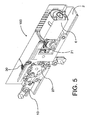
- a push-pull chain actuator 1 according to an embodiment is shown in elevated sectional and non-sectional views.
- the actuator 1 is intended to be mounted in or on a window frame 8 (shown mounted on the frame 8).
- the window frame 8 holds a sash 9 to which the external extremity of the actuator chain 10 is connected.
- the actuator 1 can be embedded in a slot in a profile of the window frame is desired.
- the external extremity of the chain 10 extending from the actuator 1 is fastened to a profile of the sash by means of a bracket 4.
- the chain is of the type that can bend freely beyond a straight line in one direction but only to a limited extent in the opposite direction. This type of chain is such well-known for push pull chain and actuators.
- An inventive chain 10 according to an embodiment of the present invention is described in detail further below. The angular movement of the sash forces the chain 10 to bend. Thus, a certain amount of sideward flexibility is required from the chain 10.
- the actuator 1 comprises a longitudinal housing 2 formed by two complementary housing shells, that can be made by a die-casting process in zinc or another suitable metal or alloy or by injection molding of a plastic or fiber reinforced plastic.
- the housing 2 is provided on one of its sides with a chain exit aperture 21 through which the chain extends from the inside of the housing 2 to the window sash 9.
- the chain exit 21 is not provided with any substantial chain guide means that are present in most conventional actuators that operate with a stiff push pull chain.
- the housing 2 is provided with a slot 40 in which a portion of the bracket 4 is received and guided.
- the bracket includes an attachment legend number 5 for facilitating the connection between the bracket 4 and the sash 9.
- the slot 40 is disposed above the chain exit aperture and extends in the direction of the chain movement trough the aperture 21.
- the slots 40 guides and receives the bracket 4.
- the chain 10 is driven by a sprocket 27.
- the sprocket 27 is connected to an electric drive motor 6 via a transmission that includes a plurality of gear wheels. These gears include a worm 21 on the drive shaft of the drive motor 6. The worm 21 engages a wormwheel 22. A further reduction gearing between the wormwheel 22 and the sprocket 27 includes gear wheels 23,24 and 25.
- a guide plate 30 guides the chain in a curve around the sprocket 27.
- the internal portion of the chain 10 is stored in a chain magazine 31.
- actuator described above can be operated with a conventional push pull chain or with an inventive push pull chain according to invention as described below.
- Figures 6-17 show an embodiment of a chain according to the present invention in very views and from various angles.
- the chain 10 includes a plurality pairs of inner links 14,14' and outer links 15,15'. Alternate pairs of the inner links 14,14' are sequentially coupled to alternate pairs 15,15' of the outer links by parallel drive pins 19 with bushings 20 that separate the pairs of inner links 14,14' and outer links 15.
- the inner links 14 and the outer links 15 on one side of bushings 20 are shaped to allow the chain 10 to bend freely past a configuration in which the chain forms a straight line in one direction and only to a limited extend in the opposite direction.
- the inner links 14' and the outer links 15' on the other side of the bushings 12 allow the chain 10 to bend in both directions.
- the inner links 14 and/or the outer links 15 that allow the chain to bend only to a limited extend are provided with lugs 17 that have abutment faces 18 for abutment with the abutment faces 18 of the lugs 17 of neighboring links 14,15 to limit the extend in which the chain 10 can be bend in the opposite direction.
- the inner links 14' and the outer links 15' that allow the chain to freely bend on both directions are not provided with such lugs and the height of the chain (10) on thus one side of the chain is therefore substantially lower than the height of the chain on the other side.
- the inner links 14' on the other side have a reduced height that is less than the height of the inner links 14 that are provided with lugs for providing and increased bearing/contact surface for the inner side surface of the links 14'.
- This side of the chain 10 with the links 14' and 15' that do not limit the freedom of movement of the chain can be easier pressed together than the links 14 and 15 on the other side of the chain 10.
- the chain needs to be flexible in a sideward direction in order to be able to curve between the tilted sash 9 and the window frame 8.
- the window chain actuator be sidewards bending is always in one and the same direction.
- the chain 10 according to the present invention will be placed such that the links 14' and 15' that do not limit the freedom of moment of the chain are placed on the radio inner side of the sideward curve of the chain 10.
- the links 14 and 15 that limit the freedom of moment of the chain and there are provided with the lugs 17 are placed on the radio the outer side of the sideward curve of the chain 10. Since the links 14' and 15' do not need to have abutment faces they can be arranged with a intermediate between them that facilitates compression of this side of the chain when the chain is being bend sidewards. In this respect it is noted that sidewards bending of the chain is facilitated by a certain amount of play between the drive pins 19 and the bushings 20.
- the chain according to the embodiment of figures 6-17 is not provided with rollers. According to a variation of this embodiment (not shown) the chain as shown in figures 6-17 is provided with rollers.
- the chain according to the invention is provided with pairs of rollers on each drive pin.
- the chain according to this embodiment has the same improved sidewards bending flexibility in one direction as the embodiments described here above.
- Figure 18 shows a variation of this embodiment and is provided with rollers 30,31 on the drive pins 19.
- the rollers 30,31 can in an embodiment have equal diameter (not shown) or (as shown) be of different diameter.
- the small diameter rollers 30 are engaged by the sprocket 27 of the actuator in which the chain is used whilst the large diameter rollers 31 engage a track that guides the chain around the sprocket 27.
- rollers are a reduction in friction losses whilst the use of double rollers provides for a further friction reduction.
Landscapes
- Engineering & Computer Science (AREA)
- General Engineering & Computer Science (AREA)
- Mechanical Engineering (AREA)
- Power-Operated Mechanisms For Wings (AREA)
- Closing And Opening Devices For Wings, And Checks For Wings (AREA)
- Window Of Vehicle (AREA)
- Lock And Its Accessories (AREA)
- Vehicle Body Suspensions (AREA)
Priority Applications (4)
| Application Number | Priority Date | Filing Date | Title |
|---|---|---|---|
| DK07016782.0T DK2034218T3 (da) | 2007-08-28 | 2007-08-28 | Tryk-trækkæde og aktuator |
| AT07016782T ATE552440T1 (de) | 2007-08-28 | 2007-08-28 | Druck-zug-kette und aktuator |
| EP07016782A EP2034218B1 (de) | 2007-08-28 | 2007-08-28 | Druck-Zug-Kette und Aktuator |
| CNA2008101469054A CN101377108A (zh) | 2007-08-28 | 2008-08-26 | 推拉链条和致动器 |
Applications Claiming Priority (1)
| Application Number | Priority Date | Filing Date | Title |
|---|---|---|---|
| EP07016782A EP2034218B1 (de) | 2007-08-28 | 2007-08-28 | Druck-Zug-Kette und Aktuator |
Publications (2)
| Publication Number | Publication Date |
|---|---|
| EP2034218A1 true EP2034218A1 (de) | 2009-03-11 |
| EP2034218B1 EP2034218B1 (de) | 2012-04-04 |
Family
ID=38969911
Family Applications (1)
| Application Number | Title | Priority Date | Filing Date |
|---|---|---|---|
| EP07016782A Active EP2034218B1 (de) | 2007-08-28 | 2007-08-28 | Druck-Zug-Kette und Aktuator |
Country Status (4)
| Country | Link |
|---|---|
| EP (1) | EP2034218B1 (de) |
| CN (1) | CN101377108A (de) |
| AT (1) | ATE552440T1 (de) |
| DK (1) | DK2034218T3 (de) |
Cited By (6)
| Publication number | Priority date | Publication date | Assignee | Title |
|---|---|---|---|---|
| CN103016617A (zh) * | 2012-12-27 | 2013-04-03 | 浙江大学 | 具有多种不同外径滚子的链条 |
| USD731569S1 (en) | 2012-07-24 | 2015-06-09 | Nordischer Maschinenbau Rud. Baader Gmbh + Co. Kg | Sprocket for chain link |
| USD734590S1 (en) | 2012-07-24 | 2015-07-14 | Nordischer Maschinenbau Rud. Baader Gmbh + Co. Kg | Chain link |
| DK178579B1 (da) * | 2012-07-24 | 2016-07-18 | Nordischer Maschb Rud Baader Gmbh + Co Kg | Kædeled, støttekæde og støtteindretning |
| EP3241968A1 (de) * | 2016-05-04 | 2017-11-08 | Roto Frank AG | Antriebseinrichtung für einen flügelrahmen eines wohndachfensters sowie wohndachfenster mit antriebseinrichtung |
| CN109268460A (zh) * | 2018-11-20 | 2019-01-25 | 宁波益捷精密机械有限公司 | 一种刚性链条推拉执行机构 |
Families Citing this family (6)
| Publication number | Priority date | Publication date | Assignee | Title |
|---|---|---|---|---|
| CN104328977A (zh) * | 2014-04-09 | 2015-02-04 | 上海锦为网络科技有限公司 | 一种远程智能控制的开关窗系统 |
| DE202015100105U1 (de) * | 2015-01-13 | 2016-04-11 | Aumüller Aumatic GmbH | Kettenschubantrieb |
| WO2017000452A1 (zh) * | 2015-06-30 | 2017-01-05 | 张铭勇 | 链杆机、牙链及链板 |
| JP6301876B2 (ja) * | 2015-07-29 | 2018-03-28 | 株式会社椿本チエイン | チェーン用屈曲制限アタッチメント |
| CN110529556A (zh) * | 2019-08-19 | 2019-12-03 | 宁波益捷精密机械有限公司 | 一种新型刚性链条 |
| CN112386083A (zh) * | 2020-11-18 | 2021-02-23 | 广东奥科伟业科技发展有限公司 | 可防止链条弯曲的推窗帘系统及其控制方法 |
Citations (15)
| Publication number | Priority date | Publication date | Assignee | Title |
|---|---|---|---|---|
| US2602345A (en) * | 1947-10-07 | 1952-07-08 | Raymond S Braumiller | Chain link and chain device formed therewith |
| US2715340A (en) * | 1950-04-29 | 1955-08-16 | Way Assauto Fab Riunite | Roller transmission chains |
| GB1484726A (en) | 1974-07-18 | 1977-09-01 | Teleflex Morse Ltd | Means for the opening and closing of angularly movable panels |
| AU516364B2 (en) * | 1979-10-15 | 1981-05-28 | Whitco Pty. Ltd. | Window winder |
| AU516700B2 (en) | 1978-01-17 | 1981-06-18 | Ogden Industries Pty Ltd | Window operator |
| US4941316A (en) | 1987-09-15 | 1990-07-17 | Bechtold Stephen K | Chain assembly |
| FR2659714A3 (fr) | 1990-03-14 | 1991-09-20 | Otelli Riccardo Carlo Otelli C | Chaine travaillant en poussee. |
| WO1994010418A1 (de) * | 1992-10-29 | 1994-05-11 | W. Hautau Gmbh | Kettenantrieb mit innenliegendem antriebsmotor |
| DE29604692U1 (de) * | 1996-03-15 | 1996-05-02 | Aug. Winkhaus GmbH & Co. KG, 48291 Telgte | Vorrichtung zum Auslenken einer drehbeweglich angeordneten Baueinheit, insbesondere eines Fensters |
| DE29816102U1 (de) * | 1998-09-08 | 1998-12-17 | D + H Mechatronic, Dingfelder + Kern GmbH, 22949 Ammersbek | Vorrichtung zum Bewegen von radial und linear geführten Elementen |
| EP1353031A1 (de) * | 2002-04-09 | 2003-10-15 | VKR Holding A/S | Kompakt-Aktuator |
| DE10238192A1 (de) * | 2002-08-21 | 2004-05-19 | Weber, Martin, Dipl.-Ing. (FH) | Verriegelungsbeschlag für kraftbetätigte Fenster |
| EP1524397A2 (de) * | 2003-10-16 | 2005-04-20 | TOPP S.p.A. | Dosenförmiger Behälter für elektrische Antriebe zur Verstellung von Verschlusselementen mittels einer Kette. |
| EP1764469A1 (de) * | 2005-09-16 | 2007-03-21 | GSG INTERNATIONAL S.p.A. | Motorisch angetriebene Fenstereinheit mit schwenkbarer Öffnung |
| EP1813757A1 (de) * | 2006-01-25 | 2007-08-01 | VKR Holding A/S | Kettenschubantrieb für Fenster |
-
2007
- 2007-08-28 EP EP07016782A patent/EP2034218B1/de active Active
- 2007-08-28 DK DK07016782.0T patent/DK2034218T3/da active
- 2007-08-28 AT AT07016782T patent/ATE552440T1/de active
-
2008
- 2008-08-26 CN CNA2008101469054A patent/CN101377108A/zh active Pending
Patent Citations (15)
| Publication number | Priority date | Publication date | Assignee | Title |
|---|---|---|---|---|
| US2602345A (en) * | 1947-10-07 | 1952-07-08 | Raymond S Braumiller | Chain link and chain device formed therewith |
| US2715340A (en) * | 1950-04-29 | 1955-08-16 | Way Assauto Fab Riunite | Roller transmission chains |
| GB1484726A (en) | 1974-07-18 | 1977-09-01 | Teleflex Morse Ltd | Means for the opening and closing of angularly movable panels |
| AU516700B2 (en) | 1978-01-17 | 1981-06-18 | Ogden Industries Pty Ltd | Window operator |
| AU516364B2 (en) * | 1979-10-15 | 1981-05-28 | Whitco Pty. Ltd. | Window winder |
| US4941316A (en) | 1987-09-15 | 1990-07-17 | Bechtold Stephen K | Chain assembly |
| FR2659714A3 (fr) | 1990-03-14 | 1991-09-20 | Otelli Riccardo Carlo Otelli C | Chaine travaillant en poussee. |
| WO1994010418A1 (de) * | 1992-10-29 | 1994-05-11 | W. Hautau Gmbh | Kettenantrieb mit innenliegendem antriebsmotor |
| DE29604692U1 (de) * | 1996-03-15 | 1996-05-02 | Aug. Winkhaus GmbH & Co. KG, 48291 Telgte | Vorrichtung zum Auslenken einer drehbeweglich angeordneten Baueinheit, insbesondere eines Fensters |
| DE29816102U1 (de) * | 1998-09-08 | 1998-12-17 | D + H Mechatronic, Dingfelder + Kern GmbH, 22949 Ammersbek | Vorrichtung zum Bewegen von radial und linear geführten Elementen |
| EP1353031A1 (de) * | 2002-04-09 | 2003-10-15 | VKR Holding A/S | Kompakt-Aktuator |
| DE10238192A1 (de) * | 2002-08-21 | 2004-05-19 | Weber, Martin, Dipl.-Ing. (FH) | Verriegelungsbeschlag für kraftbetätigte Fenster |
| EP1524397A2 (de) * | 2003-10-16 | 2005-04-20 | TOPP S.p.A. | Dosenförmiger Behälter für elektrische Antriebe zur Verstellung von Verschlusselementen mittels einer Kette. |
| EP1764469A1 (de) * | 2005-09-16 | 2007-03-21 | GSG INTERNATIONAL S.p.A. | Motorisch angetriebene Fenstereinheit mit schwenkbarer Öffnung |
| EP1813757A1 (de) * | 2006-01-25 | 2007-08-01 | VKR Holding A/S | Kettenschubantrieb für Fenster |
Cited By (9)
| Publication number | Priority date | Publication date | Assignee | Title |
|---|---|---|---|---|
| USD731569S1 (en) | 2012-07-24 | 2015-06-09 | Nordischer Maschinenbau Rud. Baader Gmbh + Co. Kg | Sprocket for chain link |
| USD734590S1 (en) | 2012-07-24 | 2015-07-14 | Nordischer Maschinenbau Rud. Baader Gmbh + Co. Kg | Chain link |
| DK178579B1 (da) * | 2012-07-24 | 2016-07-18 | Nordischer Maschb Rud Baader Gmbh + Co Kg | Kædeled, støttekæde og støtteindretning |
| US10376893B2 (en) | 2012-07-24 | 2019-08-13 | Nordischer Maschinebau RUD. Baader GMBH + Co., KG | Chain link, support chain, and support device |
| CN103016617A (zh) * | 2012-12-27 | 2013-04-03 | 浙江大学 | 具有多种不同外径滚子的链条 |
| CN103016617B (zh) * | 2012-12-27 | 2014-12-17 | 浙江大学 | 具有多种不同外径滚子的链条 |
| EP3241968A1 (de) * | 2016-05-04 | 2017-11-08 | Roto Frank AG | Antriebseinrichtung für einen flügelrahmen eines wohndachfensters sowie wohndachfenster mit antriebseinrichtung |
| CN109268460A (zh) * | 2018-11-20 | 2019-01-25 | 宁波益捷精密机械有限公司 | 一种刚性链条推拉执行机构 |
| CN109268460B (zh) * | 2018-11-20 | 2024-01-05 | 宁波益捷精密机械有限公司 | 一种刚性链条推拉执行机构 |
Also Published As
| Publication number | Publication date |
|---|---|
| DK2034218T3 (da) | 2012-07-16 |
| CN101377108A (zh) | 2009-03-04 |
| EP2034218B1 (de) | 2012-04-04 |
| ATE552440T1 (de) | 2012-04-15 |
Similar Documents
| Publication | Publication Date | Title |
|---|---|---|
| EP2034218A1 (de) | Druck-Zug-Kette und Aktuator | |
| EP2146033B1 (de) | Zug- und Druckkette sowie Stellvorrichtung | |
| EP1747386B1 (de) | Zug-druck-kette und stellglied | |
| US6257303B1 (en) | Rack and pinion door drive system | |
| US7048029B2 (en) | Sectional door | |
| PL172286B1 (pl) | Urzadzenie uruchamiajace do otwierania i zamykania skrzydel okiennych, drzwiowych, klap wentylacyjnych lub tym podobnych PL | |
| EP2131064B1 (de) | Kettenschubantrieb mit vermindertem Polygoneffekt | |
| JP6946471B2 (ja) | ロールアップドア | |
| WO2005085574A1 (en) | Window regulator | |
| JPS59145887A (ja) | モ−タ駆動式クロ−ジヤ作動装置 | |
| CA2459664A1 (en) | Garage door movement apparatus | |
| US20100229469A1 (en) | Opening/closing unit and opening/closing unit for vehicle windows | |
| US20080083167A1 (en) | Chain guide insert for a garage door | |
| EP1165921B1 (de) | Doppelkettenantrieb für tür oder fenster | |
| WO2005033455A1 (en) | Slim window actuator | |
| JP2014189040A (ja) | 可動扉装置 | |
| EP2294275A1 (de) | Rollladen mit einem antriebsmittel und antriebselement in form eines zahnriemens | |
| US9151094B2 (en) | Device for connecting door and window operating units | |
| CN101481972B (zh) | 用于窗的翼扇的驱动装置 | |
| DK2574823T3 (en) | Hinged chain | |
| EP0563517A1 (de) | Kombinierter Schub- und Zugantrieb | |
| EP2003082A1 (de) | Motorisierte Tür für Fahrkörbe von Aufzügen | |
| AU761744B2 (en) | A rack and pinion door drive system | |
| CA2599704A1 (en) | Chain guide insert for a garage door | |
| JPH1162377A (ja) | 車両ドアのウインドレギュレータ |
Legal Events
| Date | Code | Title | Description |
|---|---|---|---|
| PUAI | Public reference made under article 153(3) epc to a published international application that has entered the european phase |
Free format text: ORIGINAL CODE: 0009012 |
|
| AK | Designated contracting states |
Kind code of ref document: A1 Designated state(s): AT BE BG CH CY CZ DE DK EE ES FI FR GB GR HU IE IS IT LI LT LU LV MC MT NL PL PT RO SE SI SK TR |
|
| AX | Request for extension of the european patent |
Extension state: AL BA HR MK RS |
|
| 17P | Request for examination filed |
Effective date: 20090608 |
|
| 17Q | First examination report despatched |
Effective date: 20090724 |
|
| AKX | Designation fees paid |
Designated state(s): AT BE BG CH CY CZ DE DK EE ES FI FR GB GR HU IE IS IT LI LT LU LV MC MT NL PL PT RO SE SI SK TR |
|
| GRAP | Despatch of communication of intention to grant a patent |
Free format text: ORIGINAL CODE: EPIDOSNIGR1 |
|
| GRAS | Grant fee paid |
Free format text: ORIGINAL CODE: EPIDOSNIGR3 |
|
| GRAA | (expected) grant |
Free format text: ORIGINAL CODE: 0009210 |
|
| AK | Designated contracting states |
Kind code of ref document: B1 Designated state(s): AT BE BG CH CY CZ DE DK EE ES FI FR GB GR HU IE IS IT LI LT LU LV MC MT NL PL PT RO SE SI SK TR |
|
| REG | Reference to a national code |
Ref country code: GB Ref legal event code: FG4D |
|
| REG | Reference to a national code |
Ref country code: CH Ref legal event code: EP |
|
| REG | Reference to a national code |
Ref country code: AT Ref legal event code: REF Ref document number: 552440 Country of ref document: AT Kind code of ref document: T Effective date: 20120415 |
|
| REG | Reference to a national code |
Ref country code: IE Ref legal event code: FG4D |
|
| REG | Reference to a national code |
Ref country code: DE Ref legal event code: R096 Ref document number: 602007021708 Country of ref document: DE Effective date: 20120531 |
|
| REG | Reference to a national code |
Ref country code: CH Ref legal event code: NV Representative=s name: MURGITROYD & COMPANY |
|
| REG | Reference to a national code |
Ref country code: NL Ref legal event code: T3 |
|
| REG | Reference to a national code |
Ref country code: DK Ref legal event code: T3 |
|
| REG | Reference to a national code |
Ref country code: SE Ref legal event code: TRGR |
|
| LTIE | Lt: invalidation of european patent or patent extension |
Effective date: 20120404 |
|
| PG25 | Lapsed in a contracting state [announced via postgrant information from national office to epo] |
Ref country code: LT Free format text: LAPSE BECAUSE OF FAILURE TO SUBMIT A TRANSLATION OF THE DESCRIPTION OR TO PAY THE FEE WITHIN THE PRESCRIBED TIME-LIMIT Effective date: 20120404 Ref country code: IS Free format text: LAPSE BECAUSE OF FAILURE TO SUBMIT A TRANSLATION OF THE DESCRIPTION OR TO PAY THE FEE WITHIN THE PRESCRIBED TIME-LIMIT Effective date: 20120804 Ref country code: PL Free format text: LAPSE BECAUSE OF FAILURE TO SUBMIT A TRANSLATION OF THE DESCRIPTION OR TO PAY THE FEE WITHIN THE PRESCRIBED TIME-LIMIT Effective date: 20120404 Ref country code: CY Free format text: LAPSE BECAUSE OF FAILURE TO SUBMIT A TRANSLATION OF THE DESCRIPTION OR TO PAY THE FEE WITHIN THE PRESCRIBED TIME-LIMIT Effective date: 20120404 Ref country code: SI Free format text: LAPSE BECAUSE OF FAILURE TO SUBMIT A TRANSLATION OF THE DESCRIPTION OR TO PAY THE FEE WITHIN THE PRESCRIBED TIME-LIMIT Effective date: 20120404 Ref country code: FI Free format text: LAPSE BECAUSE OF FAILURE TO SUBMIT A TRANSLATION OF THE DESCRIPTION OR TO PAY THE FEE WITHIN THE PRESCRIBED TIME-LIMIT Effective date: 20120404 |
|
| PG25 | Lapsed in a contracting state [announced via postgrant information from national office to epo] |
Ref country code: LV Free format text: LAPSE BECAUSE OF FAILURE TO SUBMIT A TRANSLATION OF THE DESCRIPTION OR TO PAY THE FEE WITHIN THE PRESCRIBED TIME-LIMIT Effective date: 20120404 Ref country code: PT Free format text: LAPSE BECAUSE OF FAILURE TO SUBMIT A TRANSLATION OF THE DESCRIPTION OR TO PAY THE FEE WITHIN THE PRESCRIBED TIME-LIMIT Effective date: 20120806 Ref country code: GR Free format text: LAPSE BECAUSE OF FAILURE TO SUBMIT A TRANSLATION OF THE DESCRIPTION OR TO PAY THE FEE WITHIN THE PRESCRIBED TIME-LIMIT Effective date: 20120705 |
|
| PG25 | Lapsed in a contracting state [announced via postgrant information from national office to epo] |
Ref country code: BE Free format text: LAPSE BECAUSE OF FAILURE TO SUBMIT A TRANSLATION OF THE DESCRIPTION OR TO PAY THE FEE WITHIN THE PRESCRIBED TIME-LIMIT Effective date: 20120404 |
|
| PG25 | Lapsed in a contracting state [announced via postgrant information from national office to epo] |
Ref country code: CZ Free format text: LAPSE BECAUSE OF FAILURE TO SUBMIT A TRANSLATION OF THE DESCRIPTION OR TO PAY THE FEE WITHIN THE PRESCRIBED TIME-LIMIT Effective date: 20120404 Ref country code: RO Free format text: LAPSE BECAUSE OF FAILURE TO SUBMIT A TRANSLATION OF THE DESCRIPTION OR TO PAY THE FEE WITHIN THE PRESCRIBED TIME-LIMIT Effective date: 20120404 Ref country code: EE Free format text: LAPSE BECAUSE OF FAILURE TO SUBMIT A TRANSLATION OF THE DESCRIPTION OR TO PAY THE FEE WITHIN THE PRESCRIBED TIME-LIMIT Effective date: 20120404 Ref country code: SK Free format text: LAPSE BECAUSE OF FAILURE TO SUBMIT A TRANSLATION OF THE DESCRIPTION OR TO PAY THE FEE WITHIN THE PRESCRIBED TIME-LIMIT Effective date: 20120404 |
|
| PLBE | No opposition filed within time limit |
Free format text: ORIGINAL CODE: 0009261 |
|
| STAA | Information on the status of an ep patent application or granted ep patent |
Free format text: STATUS: NO OPPOSITION FILED WITHIN TIME LIMIT |
|
| 26N | No opposition filed |
Effective date: 20130107 |
|
| PG25 | Lapsed in a contracting state [announced via postgrant information from national office to epo] |
Ref country code: MC Free format text: LAPSE BECAUSE OF NON-PAYMENT OF DUE FEES Effective date: 20120831 |
|
| PG25 | Lapsed in a contracting state [announced via postgrant information from national office to epo] |
Ref country code: ES Free format text: LAPSE BECAUSE OF FAILURE TO SUBMIT A TRANSLATION OF THE DESCRIPTION OR TO PAY THE FEE WITHIN THE PRESCRIBED TIME-LIMIT Effective date: 20120715 |
|
| REG | Reference to a national code |
Ref country code: DE Ref legal event code: R097 Ref document number: 602007021708 Country of ref document: DE Effective date: 20130107 |
|
| REG | Reference to a national code |
Ref country code: IE Ref legal event code: MM4A |
|
| PG25 | Lapsed in a contracting state [announced via postgrant information from national office to epo] |
Ref country code: IE Free format text: LAPSE BECAUSE OF NON-PAYMENT OF DUE FEES Effective date: 20120828 Ref country code: BG Free format text: LAPSE BECAUSE OF FAILURE TO SUBMIT A TRANSLATION OF THE DESCRIPTION OR TO PAY THE FEE WITHIN THE PRESCRIBED TIME-LIMIT Effective date: 20120704 |
|
| PG25 | Lapsed in a contracting state [announced via postgrant information from national office to epo] |
Ref country code: MT Free format text: LAPSE BECAUSE OF FAILURE TO SUBMIT A TRANSLATION OF THE DESCRIPTION OR TO PAY THE FEE WITHIN THE PRESCRIBED TIME-LIMIT Effective date: 20120404 |
|
| PG25 | Lapsed in a contracting state [announced via postgrant information from national office to epo] |
Ref country code: TR Free format text: LAPSE BECAUSE OF FAILURE TO SUBMIT A TRANSLATION OF THE DESCRIPTION OR TO PAY THE FEE WITHIN THE PRESCRIBED TIME-LIMIT Effective date: 20120404 |
|
| PG25 | Lapsed in a contracting state [announced via postgrant information from national office to epo] |
Ref country code: LU Free format text: LAPSE BECAUSE OF NON-PAYMENT OF DUE FEES Effective date: 20120828 |
|
| PG25 | Lapsed in a contracting state [announced via postgrant information from national office to epo] |
Ref country code: HU Free format text: LAPSE BECAUSE OF FAILURE TO SUBMIT A TRANSLATION OF THE DESCRIPTION OR TO PAY THE FEE WITHIN THE PRESCRIBED TIME-LIMIT Effective date: 20070828 |
|
| PGFP | Annual fee paid to national office [announced via postgrant information from national office to epo] |
Ref country code: CH Payment date: 20140812 Year of fee payment: 8 Ref country code: NL Payment date: 20140809 Year of fee payment: 8 |
|
| PGFP | Annual fee paid to national office [announced via postgrant information from national office to epo] |
Ref country code: AT Payment date: 20140728 Year of fee payment: 8 Ref country code: SE Payment date: 20140826 Year of fee payment: 8 |
|
| REG | Reference to a national code |
Ref country code: DE Ref legal event code: R081 Ref document number: 602007021708 Country of ref document: DE Owner name: WINDOWMASTER A/S, DK Free format text: FORMER OWNER: VKR HOLDING A/S, HOERSHOLM, DK |
|
| REG | Reference to a national code |
Ref country code: GB Ref legal event code: 732E Free format text: REGISTERED BETWEEN 20150709 AND 20150715 |
|
| REG | Reference to a national code |
Ref country code: FR Ref legal event code: PLFP Year of fee payment: 9 |
|
| REG | Reference to a national code |
Ref country code: FR Ref legal event code: TP Owner name: WINDOWMASTER A/S, DK Effective date: 20150925 |
|
| REG | Reference to a national code |
Ref country code: SE Ref legal event code: EUG |
|
| REG | Reference to a national code |
Ref country code: CH Ref legal event code: PL |
|
| REG | Reference to a national code |
Ref country code: AT Ref legal event code: MM01 Ref document number: 552440 Country of ref document: AT Kind code of ref document: T Effective date: 20150828 |
|
| PG25 | Lapsed in a contracting state [announced via postgrant information from national office to epo] |
Ref country code: CH Free format text: LAPSE BECAUSE OF NON-PAYMENT OF DUE FEES Effective date: 20150831 Ref country code: LI Free format text: LAPSE BECAUSE OF NON-PAYMENT OF DUE FEES Effective date: 20150831 |
|
| REG | Reference to a national code |
Ref country code: NL Ref legal event code: MM Effective date: 20150901 |
|
| PG25 | Lapsed in a contracting state [announced via postgrant information from national office to epo] |
Ref country code: SE Free format text: LAPSE BECAUSE OF NON-PAYMENT OF DUE FEES Effective date: 20150829 Ref country code: AT Free format text: LAPSE BECAUSE OF NON-PAYMENT OF DUE FEES Effective date: 20150828 |
|
| PG25 | Lapsed in a contracting state [announced via postgrant information from national office to epo] |
Ref country code: NL Free format text: LAPSE BECAUSE OF NON-PAYMENT OF DUE FEES Effective date: 20150901 |
|
| REG | Reference to a national code |
Ref country code: FR Ref legal event code: PLFP Year of fee payment: 10 |
|
| REG | Reference to a national code |
Ref country code: FR Ref legal event code: PLFP Year of fee payment: 11 |
|
| REG | Reference to a national code |
Ref country code: FR Ref legal event code: PLFP Year of fee payment: 12 |
|
| P01 | Opt-out of the competence of the unified patent court (upc) registered |
Effective date: 20230516 |
|
| PGFP | Annual fee paid to national office [announced via postgrant information from national office to epo] |
Ref country code: IT Payment date: 20230822 Year of fee payment: 17 Ref country code: GB Payment date: 20230828 Year of fee payment: 17 |
|
| PGFP | Annual fee paid to national office [announced via postgrant information from national office to epo] |
Ref country code: FR Payment date: 20230825 Year of fee payment: 17 Ref country code: DK Payment date: 20230829 Year of fee payment: 17 Ref country code: DE Payment date: 20230829 Year of fee payment: 17 |