EP1524397A2 - Dosenförmiger Behälter für elektrische Antriebe zur Verstellung von Verschlusselementen mittels einer Kette. - Google Patents
Dosenförmiger Behälter für elektrische Antriebe zur Verstellung von Verschlusselementen mittels einer Kette. Download PDFInfo
- Publication number
- EP1524397A2 EP1524397A2 EP04024269A EP04024269A EP1524397A2 EP 1524397 A2 EP1524397 A2 EP 1524397A2 EP 04024269 A EP04024269 A EP 04024269A EP 04024269 A EP04024269 A EP 04024269A EP 1524397 A2 EP1524397 A2 EP 1524397A2
- Authority
- EP
- European Patent Office
- Prior art keywords
- box
- chain
- shell portion
- container
- shell
- Prior art date
- Legal status (The legal status is an assumption and is not a legal conclusion. Google has not performed a legal analysis and makes no representation as to the accuracy of the status listed.)
- Granted
Links
Images


Classifications
-
- E—FIXED CONSTRUCTIONS
- E05—LOCKS; KEYS; WINDOW OR DOOR FITTINGS; SAFES
- E05F—DEVICES FOR MOVING WINGS INTO OPEN OR CLOSED POSITION; CHECKS FOR WINGS; WING FITTINGS NOT OTHERWISE PROVIDED FOR, CONCERNED WITH THE FUNCTIONING OF THE WING
- E05F15/00—Power-operated mechanisms for wings
- E05F15/60—Power-operated mechanisms for wings using electrical actuators
- E05F15/603—Power-operated mechanisms for wings using electrical actuators using rotary electromotors
- E05F15/611—Power-operated mechanisms for wings using electrical actuators using rotary electromotors for swinging wings
- E05F15/616—Power-operated mechanisms for wings using electrical actuators using rotary electromotors for swinging wings operated by push-pull mechanisms
- E05F15/619—Power-operated mechanisms for wings using electrical actuators using rotary electromotors for swinging wings operated by push-pull mechanisms using flexible or rigid rack-and-pinion arrangements
-
- E—FIXED CONSTRUCTIONS
- E05—LOCKS; KEYS; WINDOW OR DOOR FITTINGS; SAFES
- E05F—DEVICES FOR MOVING WINGS INTO OPEN OR CLOSED POSITION; CHECKS FOR WINGS; WING FITTINGS NOT OTHERWISE PROVIDED FOR, CONCERNED WITH THE FUNCTIONING OF THE WING
- E05F15/00—Power-operated mechanisms for wings
- E05F15/60—Power-operated mechanisms for wings using electrical actuators
- E05F15/603—Power-operated mechanisms for wings using electrical actuators using rotary electromotors
-
- E—FIXED CONSTRUCTIONS
- E05—LOCKS; KEYS; WINDOW OR DOOR FITTINGS; SAFES
- E05F—DEVICES FOR MOVING WINGS INTO OPEN OR CLOSED POSITION; CHECKS FOR WINGS; WING FITTINGS NOT OTHERWISE PROVIDED FOR, CONCERNED WITH THE FUNCTIONING OF THE WING
- E05F11/00—Man-operated mechanisms for operating wings, including those which also operate the fastening
- E05F11/02—Man-operated mechanisms for operating wings, including those which also operate the fastening for wings in general, e.g. fanlights
- E05F11/04—Man-operated mechanisms for operating wings, including those which also operate the fastening for wings in general, e.g. fanlights with cords, chains or cables
- E05F11/06—Man-operated mechanisms for operating wings, including those which also operate the fastening for wings in general, e.g. fanlights with cords, chains or cables in guide-channels
-
- E—FIXED CONSTRUCTIONS
- E05—LOCKS; KEYS; WINDOW OR DOOR FITTINGS; SAFES
- E05Y—INDEXING SCHEME ASSOCIATED WITH SUBCLASSES E05D AND E05F, RELATING TO CONSTRUCTION ELEMENTS, ELECTRIC CONTROL, POWER SUPPLY, POWER SIGNAL OR TRANSMISSION, USER INTERFACES, MOUNTING OR COUPLING, DETAILS, ACCESSORIES, AUXILIARY OPERATIONS NOT OTHERWISE PROVIDED FOR, APPLICATION THEREOF
- E05Y2201/00—Constructional elements; Accessories therefor
- E05Y2201/60—Suspension or transmission members; Accessories therefor
- E05Y2201/622—Suspension or transmission members elements
- E05Y2201/644—Flexible elongated pulling elements
- E05Y2201/656—Chains
-
- E—FIXED CONSTRUCTIONS
- E05—LOCKS; KEYS; WINDOW OR DOOR FITTINGS; SAFES
- E05Y—INDEXING SCHEME ASSOCIATED WITH SUBCLASSES E05D AND E05F, RELATING TO CONSTRUCTION ELEMENTS, ELECTRIC CONTROL, POWER SUPPLY, POWER SIGNAL OR TRANSMISSION, USER INTERFACES, MOUNTING OR COUPLING, DETAILS, ACCESSORIES, AUXILIARY OPERATIONS NOT OTHERWISE PROVIDED FOR, APPLICATION THEREOF
- E05Y2201/00—Constructional elements; Accessories therefor
- E05Y2201/60—Suspension or transmission members; Accessories therefor
- E05Y2201/622—Suspension or transmission members elements
- E05Y2201/71—Toothed gearing
- E05Y2201/722—Racks
- E05Y2201/724—Flexible
-
- E—FIXED CONSTRUCTIONS
- E05—LOCKS; KEYS; WINDOW OR DOOR FITTINGS; SAFES
- E05Y—INDEXING SCHEME ASSOCIATED WITH SUBCLASSES E05D AND E05F, RELATING TO CONSTRUCTION ELEMENTS, ELECTRIC CONTROL, POWER SUPPLY, POWER SIGNAL OR TRANSMISSION, USER INTERFACES, MOUNTING OR COUPLING, DETAILS, ACCESSORIES, AUXILIARY OPERATIONS NOT OTHERWISE PROVIDED FOR, APPLICATION THEREOF
- E05Y2900/00—Application of doors, windows, wings or fittings thereof
- E05Y2900/10—Application of doors, windows, wings or fittings thereof for buildings or parts thereof
- E05Y2900/13—Type of wing
- E05Y2900/148—Windows
Definitions
- the present invention relates to a box-like container for electric actuators for moving shutters by means of a chain.
- Actuators for moving shutters by means of a chain which allow to open and close shutters automatically, are known and used.
- actuators comprise, within a box-like container that is fixed to the frame of the casing of the shutter, a chain that is guided slidingly by guiding elements along a preset path that leads outside through an opening in the box-like container.
- a typical box-like container used until now is composed of at least four shell portions: two outer shell portions, which are coupled and form the actual outer box-like enclosure, and two inner shell portions, which are coupled so as to form a box that provides the receptacle for the electric and electronic components and for the gear systems for actuating the chain.
- a sealing gasket is arranged between the two inner shell portions in order to prevent moisture and water from making contact with the electric and electronic components, compromising their electrical insulation and their compliance with safety standards.
- Assembly of the container entails inserting the components in a first inner shell portion; then the sealing gasket is arranged on the rim of said first inner shell portion, and finally the second inner shell portion is arranged as a cover, locking it by means of screws so as to obtain the box for containing said components.
- the box is fixed by means of screws to the bottom of a first outer shell portion, and then the movement chain, functionally connected to the gear systems contained in the inner box, is arranged.
- the second outer shell is also positioned as a cover by means of screws.
- a box-like container such as the one described has drawbacks.
- Such container is in fact scarcely efficient both in terms of number of components, in terms of intermediate connections between the components and in terms of assembly operations.
- the aim of the present invention is to provide a box-like container for electric actuators for moving shutters by means of a chain that has a simplified structure with respect to known box-like containers.
- an object of the present invention is to provide a box-like container for electric actuators for moving shutters by means of a chain that is simple and quick to assemble.
- Another object of the present invention is to provide a box-like container for electric actuators for moving shutters by means of a chain that can be manufactured at a lower cost than known box-like containers.
- Another object of the present invention is to provide a box-like container for electric actuators for moving shutters by means of a chain that can be manufactured with known systems and technologies.
- a box-like container for electric actuators for moving shutters by means of a chain characterized in that it comprises two shell portions made of plastics, which are mutually coupled so as to form the outer enclosure of said box-like container, and a third shell portion made of plastics, which is arranged inside said outer enclosure and is coupled to the inner bottom of one of said two shell portions so as to delimit a first receptacle, which is comprised between the outside of said third shell portion and said two shell portions and in which the movement chain is provided, and a second receptacle, which contains the electric and electronic components and part of the gear systems for actuating said chain, said third shell portion having an overmolded gasket on the edges for coupling to said inner bottom.
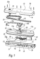
- a box-like container for electric actuators for moving shutters by means of a chain according to the invention is generally designated by the reference numeral 10.
- the box-like container 10 comprises two shell portions made of plastics, respectively a first shell portion 11 and a second shell portion 12, which are mutually coupled so as to form an outer enclosure 13 of the box-like container 10.
- Each shell portion 11 and 12 has peripheral edges 14 that have substantially the same profile in plan view.
- the first and second shell portions 11 and 12 are coupled so that their respective peripheral edges 14 are in contact; the peripheral edges 14 are further complementarily shaped with respect to each other in a transverse direction.
- a third shell portion 17 made of plastics, which is coupled to an inner bottom 18 of one of said two shell portions (in this case, to the first shell portion 11), so as to delimit in practice a first receptacle 19, which is comprised between the outside of the third shell portion 17 and the two shell portions 11 and 12, and a second receptacle 20.
- the second receptacle 20 contains the electric and electronic components and part of the actuation gear systems for said chain, which are described hereinafter.
- the first receptacle 19 contains a movement chain 15 of the actuator associated with the box-like container 10.
- the third shell portion 17 has an overmolded gasket 22 on the edges 21 for coupling to the inner bottom 18.
- the overmolded gasket 22 is inserted in a complementarily shaped sealing seat 23 provided perimetrically on the inner bottom 18.
- the third shell portion 17 is shaped so as to delimit, inside the second receptacle 20, three compartments: respectively, a first containment compartment 24 for an electric motor 25; a second compartment 26, which is adjacent to the first compartment 24 and is designed to contain part 16 of the actuation gears of the movement chain 15, which are functionally connected to the electric motor 25; and a third receptacle 27, for accommodating the electronic components, such as an electronic board 28.
- the compartments 24, 26 and 27 are mutually separated by partitions 29, which protrude from the inner bottom 18 of the first shell portion 11.
- a first through hole 30 is provided on the part 17a of the third shell portion 17 that lies opposite the inner bottom 18 of the first shell portion 11, in order to mechanically connect the part 16 of the gears for actuating the movement chain 15 to a sprocket 31, which is functionally arranged in the first receptacle 19 and transmits motion to the chain 15.
- a second through hole 32 is also provided on the part 17a of the third shell portion 17 that lies opposite the inner bottom 18 of the first shell portion 11, in order to allow the passage of the rotation pivot 33 of a ring 34 for adjusting the strokes of the chain 15; the rotation pivot 33 is functionally connected to the electronic board 28.
- the ring 34 is arranged between the third shell portion 17 and the second shell portion 12.
- the ring 34 can also be viewed through a third readout and adjustment hole 32a provided in the second shell portion 12.
- a grommet 35 is arranged between the walls of the third shell portion 17 and the walls of the outer enclosure 13 and allows the passage and locking of the electrical wires of the electrical board 28 and of the electric motor 25 from the inside of the second receptacle 20 to the outside of the box-like container 10.
- the grommet 35 is constituted by a tubular flexible portion 36 provided with a lower longitudinal slit 36a.
- the slit 36a is very handy during assembly.
- the tubular portion 36 is coupled, by means of sealing grooves 35a, by one end, to the edges of two first cutouts 37a and 37b formed on the lateral edges 14a and 14b of the shell portions 11 and 12, and by the opposite end to the edges of a second cutout 38 formed on the edge of the third shell portion 17.
- tubular portion 36 indeed acts as a grommet and as a hydraulic seal.
- the various shell portions 11, 12 and 17 are fixed by way of threaded elements 39.
- a guide 43 for the chain 15 is provided in the first receptacle 19 and is fixed on the third shell portion 17.
- the guide 43 has a part 43a for guiding the chain and an outlet 43b for the exit of the chain.
- the part 43a and the outlet 43b are monolithic, differently from known containers, in which these two components are distinct and subsequently assembled.
- the invention thus described solves the problems noted in known types of box-like container for actuators for moving shutters; in particular, the present invention provides a box-like container for electric actuators for moving shutters by means of a chain that has a simplified structure with respect to known box-like containers.
- the number of shell portions has in fact been reduced from four to three, and assembly has been simplified, eliminating the step of arranging the sealing gasket (which is now overmolded) and facilitating the assembly of the various shell portions as well as the fitting of the power supply cables.
- the materials employed may be any according to requirements and to the state of the art.
Landscapes
- Transmission Devices (AREA)
- Auxiliary Devices For And Details Of Packaging Control (AREA)
- Closing Of Containers (AREA)
- Containers And Plastic Fillers For Packaging (AREA)
- Casings For Electric Apparatus (AREA)
- Connection Of Motors, Electrical Generators, Mechanical Devices, And The Like (AREA)
- Packaging Of Annular Or Rod-Shaped Articles, Wearing Apparel, Cassettes, Or The Like (AREA)
- Packaging Frangible Articles (AREA)
Applications Claiming Priority (2)
| Application Number | Priority Date | Filing Date | Title |
|---|---|---|---|
| IT000095U ITPD20030095U1 (it) | 2003-10-16 | 2003-10-16 | Contenitore scatolare per attuatori elettrici di movimentazione per im poste tramite catena |
| ITPD20030095U | 2003-10-16 |
Publications (3)
| Publication Number | Publication Date |
|---|---|
| EP1524397A2 true EP1524397A2 (de) | 2005-04-20 |
| EP1524397A3 EP1524397A3 (de) | 2007-01-24 |
| EP1524397B1 EP1524397B1 (de) | 2009-03-04 |
Family
ID=34362431
Family Applications (1)
| Application Number | Title | Priority Date | Filing Date |
|---|---|---|---|
| EP04024269A Expired - Lifetime EP1524397B1 (de) | 2003-10-16 | 2004-10-12 | Dosenförmiger Behälter für elektrische Antriebe zur Verstellung von Verschlusselementen mittels einer Kette. |
Country Status (4)
| Country | Link |
|---|---|
| EP (1) | EP1524397B1 (de) |
| AT (1) | ATE424499T1 (de) |
| DE (1) | DE602004019741D1 (de) |
| IT (1) | ITPD20030095U1 (de) |
Cited By (8)
| Publication number | Priority date | Publication date | Assignee | Title |
|---|---|---|---|---|
| EP1970517A1 (de) * | 2007-03-12 | 2008-09-17 | TOPP S.p.A. | Schachtelähnlicher Behälter für elektrische Betätiger zur Automatisierung von Türen oder Fenstern |
| EP2034218A1 (de) * | 2007-08-28 | 2009-03-11 | VKR Holding A/S | Druck-Zug-Kette und Aktuator |
| WO2011072343A1 (en) * | 2009-12-18 | 2011-06-23 | Pacific Holdings (Aust) Pty Ltd | Chainwinder |
| CN103758425A (zh) * | 2014-01-16 | 2014-04-30 | 徐州大亚自动装备有限公司 | 链条脱档功能型窗控器 |
| CN103764934A (zh) * | 2011-03-16 | 2014-04-30 | 阿萨阿布洛伊澳大利亚有限公司 | 用于窗或门的链卷绕器 |
| EP3540163A1 (de) * | 2018-03-14 | 2019-09-18 | GEZE GmbH | Kettenantrieb |
| EP3685000A1 (de) * | 2017-07-20 | 2020-07-29 | iwis antriebssysteme GmbH & Co. KG | Linearantrieb mit rückensteifer kette |
| WO2023277707A1 (en) * | 2021-06-28 | 2023-01-05 | Assa Abloy New Zealand Limited | Actuator |
Family Cites Families (2)
| Publication number | Priority date | Publication date | Assignee | Title |
|---|---|---|---|---|
| GB2236142A (en) * | 1989-08-23 | 1991-03-27 | Cheong Bian Ng | Gate operating mechanism |
| IT1291433B1 (it) * | 1997-03-14 | 1999-01-11 | Topp Srl | Attuatore a catena articolata |
-
2003
- 2003-10-16 IT IT000095U patent/ITPD20030095U1/it unknown
-
2004
- 2004-10-12 DE DE602004019741T patent/DE602004019741D1/de not_active Expired - Lifetime
- 2004-10-12 AT AT04024269T patent/ATE424499T1/de not_active IP Right Cessation
- 2004-10-12 EP EP04024269A patent/EP1524397B1/de not_active Expired - Lifetime
Cited By (12)
| Publication number | Priority date | Publication date | Assignee | Title |
|---|---|---|---|---|
| EP1970517A1 (de) * | 2007-03-12 | 2008-09-17 | TOPP S.p.A. | Schachtelähnlicher Behälter für elektrische Betätiger zur Automatisierung von Türen oder Fenstern |
| EP2034218A1 (de) * | 2007-08-28 | 2009-03-11 | VKR Holding A/S | Druck-Zug-Kette und Aktuator |
| WO2011072343A1 (en) * | 2009-12-18 | 2011-06-23 | Pacific Holdings (Aust) Pty Ltd | Chainwinder |
| CN103764934A (zh) * | 2011-03-16 | 2014-04-30 | 阿萨阿布洛伊澳大利亚有限公司 | 用于窗或门的链卷绕器 |
| AU2012229881B2 (en) * | 2011-03-16 | 2016-11-17 | Assa Abloy Australia Pty Ltd | Chain winder for a window or door |
| CN103764934B (zh) * | 2011-03-16 | 2017-11-24 | 阿萨阿布洛伊澳大利亚有限公司 | 用于窗或门的链卷绕器 |
| CN103758425A (zh) * | 2014-01-16 | 2014-04-30 | 徐州大亚自动装备有限公司 | 链条脱档功能型窗控器 |
| CN103758425B (zh) * | 2014-01-16 | 2016-03-30 | 徐州大亚智能科技有限公司 | 链条脱档功能型窗控器 |
| EP3685000A1 (de) * | 2017-07-20 | 2020-07-29 | iwis antriebssysteme GmbH & Co. KG | Linearantrieb mit rückensteifer kette |
| EP3540163A1 (de) * | 2018-03-14 | 2019-09-18 | GEZE GmbH | Kettenantrieb |
| WO2023277707A1 (en) * | 2021-06-28 | 2023-01-05 | Assa Abloy New Zealand Limited | Actuator |
| GB2623684A (en) * | 2021-06-28 | 2024-04-24 | Assa Abloy New Zealand Ltd | Actuator |
Also Published As
| Publication number | Publication date |
|---|---|
| EP1524397A3 (de) | 2007-01-24 |
| ATE424499T1 (de) | 2009-03-15 |
| EP1524397B1 (de) | 2009-03-04 |
| DE602004019741D1 (de) | 2009-04-16 |
| ITPD20030095U1 (it) | 2005-04-17 |
Similar Documents
| Publication | Publication Date | Title |
|---|---|---|
| CA2319676C (fr) | Contacteur electromecanique | |
| EP2060942B1 (de) | Modularer Trennkasten für Lichtleiter und System für modulare Trennkästen für Lichtleiter | |
| EP1524397B1 (de) | Dosenförmiger Behälter für elektrische Antriebe zur Verstellung von Verschlusselementen mittels einer Kette. | |
| US9341248B2 (en) | Linear actuator | |
| US9329576B1 (en) | Weatherproof timer enclosure | |
| CA2955394A1 (en) | Multi-axial industrial robot | |
| RS63957B1 (sr) | Linearni motor za klizna vrata | |
| US10630008B2 (en) | Electric connecting structure and manufacturing method thereof | |
| JP6404099B2 (ja) | ドアロック装置 | |
| DE69607726T2 (de) | Gehäuse für ein elektronisches Steuergerät | |
| EP0662742B1 (de) | Hohlkörper für die Betonbauinstallation | |
| ITMI950201A1 (it) | Scatola per accogliere almeno una piastre portacircuito elettrico di un apparecchio elettrico di commutazione o di comando | |
| EP1053554B1 (de) | Elektromagnetischer schütz | |
| DE29710298U1 (de) | Antrieb für Verstelleinrichtung, insbesondere an Sitz- und Liegemöbeln | |
| GB2269489A (en) | Closure containing knock-outs, for cable entry of mounting box | |
| JP6953174B2 (ja) | キャビネット | |
| JP6275624B2 (ja) | 電気接続箱 | |
| JP2004206970A (ja) | ブッシングおよび防水コンセント | |
| EP1970517B1 (de) | Schachtelähnlicher Behälter für elektrische Betätiger zur Automatisierung von Türen oder Fenstern | |
| US20190132970A1 (en) | Electrically insulative case inluding frame having plurality of possible orientations | |
| JPH10134879A (ja) | ケ−ブル接続部用防水ケ−ス | |
| ES2983658T3 (es) | Embellecedor y conmutador eléctrico que comprende dicho embellecedor | |
| JPH05144506A (ja) | 防雨形ジヨイントボツクス | |
| DE202007013667U1 (de) | Modulares Aufputz-Elektro-Installationsprogramm in schwerer Ausführung | |
| US20020063977A1 (en) | Adjusting device for motor vehicle outside mirrors |
Legal Events
| Date | Code | Title | Description |
|---|---|---|---|
| PUAI | Public reference made under article 153(3) epc to a published international application that has entered the european phase |
Free format text: ORIGINAL CODE: 0009012 |
|
| AK | Designated contracting states |
Kind code of ref document: A2 Designated state(s): AT BE BG CH CY CZ DE DK EE ES FI FR GB GR HU IE IT LI LU MC NL PL PT RO SE SI SK TR |
|
| AX | Request for extension of the european patent |
Extension state: AL HR LT LV MK |
|
| PUAL | Search report despatched |
Free format text: ORIGINAL CODE: 0009013 |
|
| AK | Designated contracting states |
Kind code of ref document: A3 Designated state(s): AT BE BG CH CY CZ DE DK EE ES FI FR GB GR HU IE IT LI LU MC NL PL PT RO SE SI SK TR |
|
| AX | Request for extension of the european patent |
Extension state: AL HR LT LV MK |
|
| RIC1 | Information provided on ipc code assigned before grant |
Ipc: E05F 15/12 20060101AFI20050222BHEP Ipc: E05F 15/10 20060101ALI20061221BHEP Ipc: E05F 11/06 20060101ALI20061221BHEP |
|
| 17P | Request for examination filed |
Effective date: 20070619 |
|
| AKX | Designation fees paid |
Designated state(s): AT BE BG CH CY CZ DE DK EE ES FI FR GB GR HU IE IT LI LU MC NL PL PT RO SE SI SK TR |
|
| GRAP | Despatch of communication of intention to grant a patent |
Free format text: ORIGINAL CODE: EPIDOSNIGR1 |
|
| GRAS | Grant fee paid |
Free format text: ORIGINAL CODE: EPIDOSNIGR3 |
|
| GRAA | (expected) grant |
Free format text: ORIGINAL CODE: 0009210 |
|
| AK | Designated contracting states |
Kind code of ref document: B1 Designated state(s): AT BE BG CH CY CZ DE DK EE ES FI FR GB GR HU IE IT LI LU MC NL PL PT RO SE SI SK TR |
|
| REG | Reference to a national code |
Ref country code: GB Ref legal event code: FG4D |
|
| REG | Reference to a national code |
Ref country code: CH Ref legal event code: EP |
|
| REG | Reference to a national code |
Ref country code: IE Ref legal event code: FG4D |
|
| REF | Corresponds to: |
Ref document number: 602004019741 Country of ref document: DE Date of ref document: 20090416 Kind code of ref document: P |
|
| PG25 | Lapsed in a contracting state [announced via postgrant information from national office to epo] |
Ref country code: NL Free format text: LAPSE BECAUSE OF FAILURE TO SUBMIT A TRANSLATION OF THE DESCRIPTION OR TO PAY THE FEE WITHIN THE PRESCRIBED TIME-LIMIT Effective date: 20090304 Ref country code: SI Free format text: LAPSE BECAUSE OF FAILURE TO SUBMIT A TRANSLATION OF THE DESCRIPTION OR TO PAY THE FEE WITHIN THE PRESCRIBED TIME-LIMIT Effective date: 20090304 Ref country code: FI Free format text: LAPSE BECAUSE OF FAILURE TO SUBMIT A TRANSLATION OF THE DESCRIPTION OR TO PAY THE FEE WITHIN THE PRESCRIBED TIME-LIMIT Effective date: 20090304 |
|
| NLV1 | Nl: lapsed or annulled due to failure to fulfill the requirements of art. 29p and 29m of the patents act | ||
| PG25 | Lapsed in a contracting state [announced via postgrant information from national office to epo] |
Ref country code: SE Free format text: LAPSE BECAUSE OF FAILURE TO SUBMIT A TRANSLATION OF THE DESCRIPTION OR TO PAY THE FEE WITHIN THE PRESCRIBED TIME-LIMIT Effective date: 20090604 Ref country code: PL Free format text: LAPSE BECAUSE OF FAILURE TO SUBMIT A TRANSLATION OF THE DESCRIPTION OR TO PAY THE FEE WITHIN THE PRESCRIBED TIME-LIMIT Effective date: 20090304 Ref country code: AT Free format text: LAPSE BECAUSE OF FAILURE TO SUBMIT A TRANSLATION OF THE DESCRIPTION OR TO PAY THE FEE WITHIN THE PRESCRIBED TIME-LIMIT Effective date: 20090304 |
|
| PG25 | Lapsed in a contracting state [announced via postgrant information from national office to epo] |
Ref country code: BE Free format text: LAPSE BECAUSE OF FAILURE TO SUBMIT A TRANSLATION OF THE DESCRIPTION OR TO PAY THE FEE WITHIN THE PRESCRIBED TIME-LIMIT Effective date: 20090304 |
|
| PG25 | Lapsed in a contracting state [announced via postgrant information from national office to epo] |
Ref country code: ES Free format text: LAPSE BECAUSE OF FAILURE TO SUBMIT A TRANSLATION OF THE DESCRIPTION OR TO PAY THE FEE WITHIN THE PRESCRIBED TIME-LIMIT Effective date: 20090615 Ref country code: CZ Free format text: LAPSE BECAUSE OF FAILURE TO SUBMIT A TRANSLATION OF THE DESCRIPTION OR TO PAY THE FEE WITHIN THE PRESCRIBED TIME-LIMIT Effective date: 20090304 Ref country code: EE Free format text: LAPSE BECAUSE OF FAILURE TO SUBMIT A TRANSLATION OF THE DESCRIPTION OR TO PAY THE FEE WITHIN THE PRESCRIBED TIME-LIMIT Effective date: 20090304 Ref country code: PT Free format text: LAPSE BECAUSE OF FAILURE TO SUBMIT A TRANSLATION OF THE DESCRIPTION OR TO PAY THE FEE WITHIN THE PRESCRIBED TIME-LIMIT Effective date: 20090819 |
|
| PG25 | Lapsed in a contracting state [announced via postgrant information from national office to epo] |
Ref country code: SK Free format text: LAPSE BECAUSE OF FAILURE TO SUBMIT A TRANSLATION OF THE DESCRIPTION OR TO PAY THE FEE WITHIN THE PRESCRIBED TIME-LIMIT Effective date: 20090304 Ref country code: RO Free format text: LAPSE BECAUSE OF FAILURE TO SUBMIT A TRANSLATION OF THE DESCRIPTION OR TO PAY THE FEE WITHIN THE PRESCRIBED TIME-LIMIT Effective date: 20090304 |
|
| PLBE | No opposition filed within time limit |
Free format text: ORIGINAL CODE: 0009261 |
|
| STAA | Information on the status of an ep patent application or granted ep patent |
Free format text: STATUS: NO OPPOSITION FILED WITHIN TIME LIMIT |
|
| PG25 | Lapsed in a contracting state [announced via postgrant information from national office to epo] |
Ref country code: DK Free format text: LAPSE BECAUSE OF FAILURE TO SUBMIT A TRANSLATION OF THE DESCRIPTION OR TO PAY THE FEE WITHIN THE PRESCRIBED TIME-LIMIT Effective date: 20090304 Ref country code: BG Free format text: LAPSE BECAUSE OF FAILURE TO SUBMIT A TRANSLATION OF THE DESCRIPTION OR TO PAY THE FEE WITHIN THE PRESCRIBED TIME-LIMIT Effective date: 20090604 |
|
| 26N | No opposition filed |
Effective date: 20091207 |
|
| PG25 | Lapsed in a contracting state [announced via postgrant information from national office to epo] |
Ref country code: MC Free format text: LAPSE BECAUSE OF NON-PAYMENT OF DUE FEES Effective date: 20091031 |
|
| REG | Reference to a national code |
Ref country code: CH Ref legal event code: PL |
|
| REG | Reference to a national code |
Ref country code: IE Ref legal event code: MM4A |
|
| REG | Reference to a national code |
Ref country code: FR Ref legal event code: ST Effective date: 20100630 |
|
| PG25 | Lapsed in a contracting state [announced via postgrant information from national office to epo] |
Ref country code: FR Free format text: LAPSE BECAUSE OF NON-PAYMENT OF DUE FEES Effective date: 20091102 |
|
| PG25 | Lapsed in a contracting state [announced via postgrant information from national office to epo] |
Ref country code: IE Free format text: LAPSE BECAUSE OF NON-PAYMENT OF DUE FEES Effective date: 20091012 Ref country code: LI Free format text: LAPSE BECAUSE OF NON-PAYMENT OF DUE FEES Effective date: 20091031 Ref country code: CH Free format text: LAPSE BECAUSE OF NON-PAYMENT OF DUE FEES Effective date: 20091031 Ref country code: GR Free format text: LAPSE BECAUSE OF FAILURE TO SUBMIT A TRANSLATION OF THE DESCRIPTION OR TO PAY THE FEE WITHIN THE PRESCRIBED TIME-LIMIT Effective date: 20090605 |
|
| PG25 | Lapsed in a contracting state [announced via postgrant information from national office to epo] |
Ref country code: LU Free format text: LAPSE BECAUSE OF NON-PAYMENT OF DUE FEES Effective date: 20091012 |
|
| PG25 | Lapsed in a contracting state [announced via postgrant information from national office to epo] |
Ref country code: HU Free format text: LAPSE BECAUSE OF FAILURE TO SUBMIT A TRANSLATION OF THE DESCRIPTION OR TO PAY THE FEE WITHIN THE PRESCRIBED TIME-LIMIT Effective date: 20090905 |
|
| PG25 | Lapsed in a contracting state [announced via postgrant information from national office to epo] |
Ref country code: TR Free format text: LAPSE BECAUSE OF FAILURE TO SUBMIT A TRANSLATION OF THE DESCRIPTION OR TO PAY THE FEE WITHIN THE PRESCRIBED TIME-LIMIT Effective date: 20090304 |
|
| PG25 | Lapsed in a contracting state [announced via postgrant information from national office to epo] |
Ref country code: CY Free format text: LAPSE BECAUSE OF FAILURE TO SUBMIT A TRANSLATION OF THE DESCRIPTION OR TO PAY THE FEE WITHIN THE PRESCRIBED TIME-LIMIT Effective date: 20090304 |
|
| PGFP | Annual fee paid to national office [announced via postgrant information from national office to epo] |
Ref country code: GB Payment date: 20231019 Year of fee payment: 20 |
|
| PGFP | Annual fee paid to national office [announced via postgrant information from national office to epo] |
Ref country code: IT Payment date: 20231024 Year of fee payment: 20 Ref country code: DE Payment date: 20231020 Year of fee payment: 20 |
|
| REG | Reference to a national code |
Ref country code: DE Ref legal event code: R071 Ref document number: 602004019741 Country of ref document: DE |
|
| REG | Reference to a national code |
Ref country code: GB Ref legal event code: PE20 Expiry date: 20241011 |
|
| PG25 | Lapsed in a contracting state [announced via postgrant information from national office to epo] |
Ref country code: GB Free format text: LAPSE BECAUSE OF EXPIRATION OF PROTECTION Effective date: 20241011 |
|
| PG25 | Lapsed in a contracting state [announced via postgrant information from national office to epo] |
Ref country code: GB Free format text: LAPSE BECAUSE OF EXPIRATION OF PROTECTION Effective date: 20241011 |