EP2034084A1 - Sèche-linge doté d'un échangeur thermique additionnel - Google Patents
Sèche-linge doté d'un échangeur thermique additionnel Download PDFInfo
- Publication number
- EP2034084A1 EP2034084A1 EP08020691A EP08020691A EP2034084A1 EP 2034084 A1 EP2034084 A1 EP 2034084A1 EP 08020691 A EP08020691 A EP 08020691A EP 08020691 A EP08020691 A EP 08020691A EP 2034084 A1 EP2034084 A1 EP 2034084A1
- Authority
- EP
- European Patent Office
- Prior art keywords
- fan
- heat exchanger
- temperature
- compressor
- dryer according
- Prior art date
- Legal status (The legal status is an assumption and is not a legal conclusion. Google has not performed a legal analysis and makes no representation as to the accuracy of the status listed.)
- Granted
Links
- 239000003570 air Substances 0.000 claims description 33
- 238000000034 method Methods 0.000 claims description 29
- 239000012080 ambient air Substances 0.000 claims description 23
- 238000001816 cooling Methods 0.000 claims description 11
- 230000001419 dependent effect Effects 0.000 claims description 4
- 238000001035 drying Methods 0.000 claims description 3
- 230000018044 dehydration Effects 0.000 claims 1
- 238000006297 dehydration reaction Methods 0.000 claims 1
- 238000003303 reheating Methods 0.000 claims 1
- 238000009423 ventilation Methods 0.000 description 8
- 238000001704 evaporation Methods 0.000 description 6
- 230000008020 evaporation Effects 0.000 description 6
- 238000010438 heat treatment Methods 0.000 description 5
- 238000009833 condensation Methods 0.000 description 3
- 230000005494 condensation Effects 0.000 description 3
- 238000011144 upstream manufacturing Methods 0.000 description 3
- XLYOFNOQVPJJNP-UHFFFAOYSA-N water Substances O XLYOFNOQVPJJNP-UHFFFAOYSA-N 0.000 description 3
- 239000003507 refrigerant Substances 0.000 description 2
- 230000001105 regulatory effect Effects 0.000 description 2
- 230000007423 decrease Effects 0.000 description 1
- 238000011161 development Methods 0.000 description 1
- 238000010586 diagram Methods 0.000 description 1
- 238000000605 extraction Methods 0.000 description 1
- 238000009533 lab test Methods 0.000 description 1
- 238000005259 measurement Methods 0.000 description 1
- 238000000465 moulding Methods 0.000 description 1
- 238000013021 overheating Methods 0.000 description 1
Images


Classifications
-
- D—TEXTILES; PAPER
- D06—TREATMENT OF TEXTILES OR THE LIKE; LAUNDERING; FLEXIBLE MATERIALS NOT OTHERWISE PROVIDED FOR
- D06F—LAUNDERING, DRYING, IRONING, PRESSING OR FOLDING TEXTILE ARTICLES
- D06F58/00—Domestic laundry dryers
- D06F58/20—General details of domestic laundry dryers
- D06F58/206—Heat pump arrangements
-
- D—TEXTILES; PAPER
- D06—TREATMENT OF TEXTILES OR THE LIKE; LAUNDERING; FLEXIBLE MATERIALS NOT OTHERWISE PROVIDED FOR
- D06F—LAUNDERING, DRYING, IRONING, PRESSING OR FOLDING TEXTILE ARTICLES
- D06F2103/00—Parameters monitored or detected for the control of domestic laundry washing machines, washer-dryers or laundry dryers
- D06F2103/28—Air properties
- D06F2103/36—Flow or velocity
-
- D—TEXTILES; PAPER
- D06—TREATMENT OF TEXTILES OR THE LIKE; LAUNDERING; FLEXIBLE MATERIALS NOT OTHERWISE PROVIDED FOR
- D06F—LAUNDERING, DRYING, IRONING, PRESSING OR FOLDING TEXTILE ARTICLES
- D06F2103/00—Parameters monitored or detected for the control of domestic laundry washing machines, washer-dryers or laundry dryers
- D06F2103/50—Parameters monitored or detected for the control of domestic laundry washing machines, washer-dryers or laundry dryers related to heat pumps, e.g. pressure or flow rate
-
- D—TEXTILES; PAPER
- D06—TREATMENT OF TEXTILES OR THE LIKE; LAUNDERING; FLEXIBLE MATERIALS NOT OTHERWISE PROVIDED FOR
- D06F—LAUNDERING, DRYING, IRONING, PRESSING OR FOLDING TEXTILE ARTICLES
- D06F2105/00—Systems or parameters controlled or affected by the control systems of washing machines, washer-dryers or laundry dryers
- D06F2105/16—Air properties
- D06F2105/24—Flow or velocity
-
- D—TEXTILES; PAPER
- D06—TREATMENT OF TEXTILES OR THE LIKE; LAUNDERING; FLEXIBLE MATERIALS NOT OTHERWISE PROVIDED FOR
- D06F—LAUNDERING, DRYING, IRONING, PRESSING OR FOLDING TEXTILE ARTICLES
- D06F2105/00—Systems or parameters controlled or affected by the control systems of washing machines, washer-dryers or laundry dryers
- D06F2105/26—Heat pumps
-
- D—TEXTILES; PAPER
- D06—TREATMENT OF TEXTILES OR THE LIKE; LAUNDERING; FLEXIBLE MATERIALS NOT OTHERWISE PROVIDED FOR
- D06F—LAUNDERING, DRYING, IRONING, PRESSING OR FOLDING TEXTILE ARTICLES
- D06F2105/00—Systems or parameters controlled or affected by the control systems of washing machines, washer-dryers or laundry dryers
- D06F2105/32—Air flow control means
-
- D—TEXTILES; PAPER
- D06—TREATMENT OF TEXTILES OR THE LIKE; LAUNDERING; FLEXIBLE MATERIALS NOT OTHERWISE PROVIDED FOR
- D06F—LAUNDERING, DRYING, IRONING, PRESSING OR FOLDING TEXTILE ARTICLES
- D06F58/00—Domestic laundry dryers
- D06F58/32—Control of operations performed in domestic laundry dryers
- D06F58/34—Control of operations performed in domestic laundry dryers characterised by the purpose or target of the control
- D06F58/48—Control of the energy consumption
-
- Y—GENERAL TAGGING OF NEW TECHNOLOGICAL DEVELOPMENTS; GENERAL TAGGING OF CROSS-SECTIONAL TECHNOLOGIES SPANNING OVER SEVERAL SECTIONS OF THE IPC; TECHNICAL SUBJECTS COVERED BY FORMER USPC CROSS-REFERENCE ART COLLECTIONS [XRACs] AND DIGESTS
- Y02—TECHNOLOGIES OR APPLICATIONS FOR MITIGATION OR ADAPTATION AGAINST CLIMATE CHANGE
- Y02B—CLIMATE CHANGE MITIGATION TECHNOLOGIES RELATED TO BUILDINGS, e.g. HOUSING, HOUSE APPLIANCES OR RELATED END-USER APPLICATIONS
- Y02B40/00—Technologies aiming at improving the efficiency of home appliances, e.g. induction cooking or efficient technologies for refrigerators, freezers or dish washers
Definitions
- the invention relates to a tumble dryer according to the preamble of claim 1.
- Dryers of this type in which the condenser and the evaporator of a heat pump cycle are used for cooling and heating, are characterized by a high efficiency. It turns out, however, that they have to be deprived of heat, otherwise the temperature in the heat pump cycle can rise to high levels.
- DE 44 34 205 and DE 44 09 607 Devices are described in which inter alia, an additional heat exchanger between the condenser and the throttle body of the heat pump cycle is arranged.
- a fan is used to cool the additional heat exchanger.
- the object of the present invention is the improvement of such a device. This object is achieved by the device according to claim 1.
- the additional heat exchanger is thus arranged in the heat pump cycle between the condenser and the throttle body. At this point, the temperature of the medium is relatively high, which improves the efficiency of the additional heat exchanger. In addition, the temperature difference between evaporator and condenser is increased by the additional heat exchanger, which makes it possible to extract more water from the process air.
- the device has a drum 1 for receiving the laundry to be dried. It is a process cycle provided (which in Fig. 1 shown by solid lines), in which heated process air passed through the drum 1, then cooled and then reheated and fed back into the drum 1.
- an optional additional electrical heating (starting heating) 9 can be provided, which allows heat to be specifically supplied to the process air, e.g. when starting the device, or it can be used to raise the temperature level in the process cycle in general.
- a blower 10 serves to pump over the process air.
- a heat pump cycle is provided (the path of the pumped by the heat pump cycle medium in Fig. 1 shown with dotted lines).
- the medium is conveyed from a compressor 2 to a condenser 3, from there to an additional heat exchanger 4, then via a throttle body 5, for example in the form of capillaries or an expansion valve, to an evaporator 6 and then back to the compressor 2.
- the evaporator. 6 serves to cool the process air and thereby deprive it of water while the condenser 3 serves to reheat the process air so that it can absorb new water.
- a fan 7 is provided, with which ambient air is passed through the additional heat exchanger 4 in order to cool it.
- the additional heat exchanger 4 is used to extract heat from the heat pump cycle and thus the entire system.
- the amount of heat extracted is controlled depending on the temperature in the heat pump cycle (and / or depending on the temperature in the process cycle), e.g. by operating the blower 7 with greater power as the temperature rises.
- the fan can be turned on only when the temperature exceeds a predetermined threshold.
- the power of the fan 7 is continuously increased with increasing temperature.
- the temperature-dependent control of the fan 7 allows, e.g. When starting the tumble dryer to supply energy to the process cycle very quickly, so that the process temperature is reached quickly, after which overheating of the heat pump cycle is prevented in normal operation.
- the temperature of the running in the heat pump cycle medium after the additional heat exchanger 4 and before the throttle body 5 is used to control the fan 7.
- the device For driving the fan 7, the device has a suitably designed control and suitable temperature sensors 40, 41. Preferably, at least the temperature T1 at the inlet of the throttle body 5 is measured.
- the present invention can be used independently of the medium used in the heat pump cycle.
- the embodiment described below works, for example, with R134a, the same principle can be used with appropriate dimensioning but also eg in a CO 2 cycle.
- a clothes dryer which has a drum 1 can be fed from the front.
- a (not shown in the figures) drive provided with which the drum can be rotated about a horizontal axis of rotation.
- the process air passes from the interior of the drum in a known manner through a sieve or more sieves in the door (not shown) of the device and / or to the door and then passes through the evaporator 6, the condenser 3, the fan 10 (see Fig. 3 ), the optional auxiliary heating (starting heating) 9 and is passed through holes 11 in the rear wall of the drum 1 back into the drum.
- the process air passes from the interior of the drum in a known manner through a sieve or more sieves in the door (not shown) of the device and / or to the door and then passes through the evaporator 6, the condenser 3, the fan 10 (see Fig. 3 ), the optional auxiliary heating (starting heating) 9 and is passed through holes 11 in the rear wall of the drum 1 back into the drum.
- a channel housing 12 see Fig. 2 .
- the heat pump cycle is located in the bottom of the unit and is best off Fig. 4 and 5 seen.
- the floor area is divided into two adjacent areas 14 and 15, each of which extends from the front 16 of the appliance to the rear 17 thereof.
- the additional heat exchanger 4, the evaporator 6 and the condenser 3 can each be constructed of identical modules.
- Each module has a meandering tube which is in thermal contact with a plurality of heat exchanger plates 20. Of the heat exchanger plates only the outermost are shown in the figures. The process air or the ambient air is guided through the gaps between the heat exchanger plates.
- the condenser 3 consists of three modules, the evaporator 6 of two modules and the additional heat exchanger 4 of only one module.
- the number of modules can be adapted to the respective requirements.
- the additional heat exchanger 4 may also comprise two or more modules, which may be traversed sequentially or in parallel by the medium of the heat pump cycle.
- the ambient air is sucked in by the first fan 18, via a suction port 22 in the base 23 at the front of the device (see Fig. 2 ).
- the air passes to the additional heat exchanger 4, then to the compressor 2 and then to the second fan 19.
- An arranged above the additional heat exchanger 4 air guide molding 25 serves to guide the air in the area of the additional heat exchanger 4.
- an air guide 26 is provided which guides the air under the (not shown) behind the second fan 19 arranged drive the drum 1 through to ventilation openings 27 on the back 17 of the device. Additional vents may be provided in the bottom of the device.
- the ambient air is passed through the compressor 2, this can also be cooled.
- the cold ambient air is first passed over the additional heat exchanger 4, as a larger amount of heat can be dissipated via this.
- the ambient air flows through the additional heat exchanger 4 from front to rear, while the medium of the heat exchanger circuit first passes through the rear side of the additional heat exchanger 4 and then only the front side, so that the additional heat exchanger 4 is hotter on the rear side than on the front side.
- the efficiency of the cooling can be improved.
- the ambient air is sucked through an opening 22 on the front 16 of the device, then passes through the first fan 18, then the additional heat exchanger 4, then the compressor 2 and finally by the second fan 19.
- the suction of the air from The front 16 has the advantage that the sucked air is relatively cool, so that a good cooling of the additional heat exchanger 4 can be achieved.
- Conceivable is also a suction of ambient air from the back and / or bottom of the device ago, or the ambient air can be sucked in by openings on the side wall of the device, as far as there ensures sufficient distance to adjacent walls or other devices is.
- the first fan 18 is larger and promotes more air than the second fan 19. This causes some of the air is not on the second fan 19 back to the outside, but the device via vents 29 in the upper part of the rear wall steps outside. On its way to the ventilation openings 29, this air can additionally cool other parts of the appliance, e.g. the drum 1.
- the second fan 19 was used to blow air back from the compressor 2 forth to the outside. In a further preferred embodiment, however, the second fan 19 is operated so that it also blows ambient air into the interior of the device. This has the advantage that the compressor 2 is blown by two sides approximately opposite each other and thus better cooled. In this case, the air from the two fans 18, 19 can additionally cool other parts of the appliance, e.g. Drum 1, and then e.g. exit through the ventilation openings 29 in the upper part of the rear wall again.
- both fans 18, 19 are controlled depending on the temperature in the heat pump cycle and / or process cycle. It is also conceivable, however, a separate control depending on the local temperature in the associated device areas.
- the blower 7 is preferably operated at a higher power when the temperature rises.
- This increase can be stepless or in steps.
- the table shows the amount of cooling air as a percentage of the volume flow of the delivered air volume relative to the maximum amount of air that can be conveyed by the ventilation 7.
- a temperature sensor 40 for measuring the temperature T1 can be arranged in front of the throttle body 5, as shown in FIG Fig. 1 is illustrated.
- the above table is to be understood as an example.
- the gradation may also be coarser or finer, or a continuous dependence between flow rate and temperature may be used.
- a multi-stage dependency or a continuous dependency allows a finer control of energy extraction than a "binary" on-off control. It turns out that this process can shorten the process time by a few minutes.
- step changes are preferably not made arbitrarily fast, but e.g. at most once a minute.
- the ventilation or the fan can be operated continuously with reduced power after the start of the drying program.
- the tumble dryer is thus designed so that during the drying process, the fan can be operated continuously on at least a first power level, wherein the power level is increased gradually or continuously as the temperature increases in the heat pump cycle.
- an AC motor When an AC motor is used to drive the fan 7, it is preferably driven in a pulsed manner by a zero-crossing switch (or by a zero-crossing control, i.e., a zero-crossing switch controlled by a control).
- a zero-crossing switch or by a zero-crossing control, i.e., a zero-crossing switch controlled by a control.
- Such zero-crossing switches are known to the person skilled in the art. They interrupt and activate the supply of the motor at the zero crossing of the current or the voltage.
- By supplying power to the motor by means of a zero-crossing switch with pulses of different length or duty cycle it can be varied in steps.
- an unwanted noise development can be avoided by this measure.
- Conceivable but more expensive, is also a control of the AC motor via AC voltages of different heights, e.g. over several transformer taps.
- the power of the blower 7 or the fan 18 and / or 19 is preferably controlled as a function of the temperature upstream of the throttle element 5.
- An improved variant of such a control is in Fig. 6 illustrated. This is based on the consideration that it is also possible by appropriate control of the fan power to prevent condensing of the medium upstream of the compressor 2. A partial or even complete condensation of the medium in front of the compressor can take place if the temperature T2 is too low at this location and at the same time a relatively high pressure prevails. It is undesirable because it can lead to damage of the compressor 2.
- the power of the fan 18 and / or 19 is as possible regulated so that the heat pump cycle less energy is withdrawn, if a condensation threatens.
- a second temperature sensor 41 is provided, with which the temperature T2 after the evaporator 6 and before the compressor 2 can be measured, in particular as close as possible in front of the compressor 2. The control of the fan power takes place in this case depending on the temperatures T1 and T2.
- control of the fan power is dependent on T1 and of the temperature difference T1 - T2.
- performance of the ventilation is increased depending on how much the temperature T1 is above the reference temperature T0.
- the reference temperature T0 is set depending on the course of the temperature difference T1 - T2. It can be seen that the temperature difference T1 - T2 is a good measure for comparison with the temperature T2 to determine whether there is a risk of condenser out of the medium.
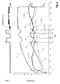
- Fig. 6 A typical drying process of a preferred embodiment of the invention is shown.
- the upper curve represents the output of the blower 7, while the lower curves represent the different temperatures T1, T2 and T1-T2, and the evaporation temperature Tv of the medium between the evaporator 6 and the compressor 2.
- the evaporation temperature Tv was calculated from the temperature T2 and from a measurement of the measured pressure of the medium between evaporator 6 and compressor 2. (The determination of the evaporation temperature Tv was carried out as part of a laboratory experiment - in normal operation of a device according to the invention Tv does not need to be determined.)
- the temperature T1 is compared with the reference temperature T0, and the power of the fan 7 is gradually increased in the manner shown in the above table, the more the temperature T1 exceeds the threshold T0.
- the reference temperature T0 is 64 ° C.
- the reference temperature becomes T0. by a predetermined offset of eg approx. Increased 15 ° C, for example, to 79 ° C. In the example of Fig. 6 this is the case for the first time at time t1.
- the reference temperature T0 is held at the higher value until the condition T1-T2 ⁇ T2-H is satisfied, where H is a hysteresis value of, for example, 10 ° C. This is in Fig. 6 for the first time at time t2. Then the reference temperature T0 is lowered again to the lower value, whereby the cooling is intensified. As soon as T1 - T2> T2 (time t3), the reference temperature T0 is reset to the higher value. This process is always repeated (in Fig. 6 at times t4 and t5) when the threshold conditions T1-T2 ⁇ T2-H and T1-T2> T2 are traversed, respectively.
- the temperature T2 is always above the evaporation temperature Tv, so that a condensation of the medium is prevented. Thus, it can be ensured by comparing the difference T1 - T2 with the temperature T2 that no subcooling of the medium takes place before the compressor 2.
- the procedure according to Fig. 6 is controlled by the aforementioned control of the device, which evaluates the signals of the temperature sensors T1 and T2, determines the reference temperature T0 and controls the power of the fan 7.
- T1-T2 is an indicator of evaporation temperature
- T2 is a measure of how close the system is to low refrigerant superheat. The measure works particularly well in the present case, since T1 is regulated to a practically fixed value.
- T2 the temperature difference between T2 of the temperature in the middle of the evaporator would be measured, or by the pressure in the region of the evaporator is determined.
- an additional temperature or pressure sensor would be necessary.
Priority Applications (2)
| Application Number | Priority Date | Filing Date | Title |
|---|---|---|---|
| PL08020691T PL2034084T3 (pl) | 2006-11-06 | 2007-11-06 | Suszarka do bielizny z dodatkowym wymiennikiem ciepła |
| SI200731226T SI2034084T1 (sl) | 2006-11-06 | 2007-11-06 | Sušilnik perila z dodatnim toplotnim prenosnikom |
Applications Claiming Priority (3)
| Application Number | Priority Date | Filing Date | Title |
|---|---|---|---|
| CH17552006 | 2006-11-06 | ||
| DE202007000648U DE202007000648U1 (de) | 2006-11-06 | 2007-01-16 | Wäschetrockner mit Zusatzwärmetauscher |
| EP07021533A EP1884586A3 (fr) | 2006-11-06 | 2007-11-06 | Sèche-linge avec échangeur de chaleur supplémentaire |
Related Parent Applications (2)
| Application Number | Title | Priority Date | Filing Date |
|---|---|---|---|
| EP07021533A Division EP1884586A3 (fr) | 2006-11-06 | 2007-11-06 | Sèche-linge avec échangeur de chaleur supplémentaire |
| EP07021533.0 Division | 2007-11-06 |
Publications (2)
| Publication Number | Publication Date |
|---|---|
| EP2034084A1 true EP2034084A1 (fr) | 2009-03-11 |
| EP2034084B1 EP2034084B1 (fr) | 2013-02-27 |
Family
ID=37776327
Family Applications (1)
| Application Number | Title | Priority Date | Filing Date |
|---|---|---|---|
| EP08020691A Active EP2034084B1 (fr) | 2006-11-06 | 2007-11-06 | Sèche-linge doté d'un échangeur thermique additionnel |
Country Status (5)
| Country | Link |
|---|---|
| EP (1) | EP2034084B1 (fr) |
| DE (2) | DE202006018205U1 (fr) |
| DK (1) | DK2034084T3 (fr) |
| PL (1) | PL2034084T3 (fr) |
| SI (1) | SI2034084T1 (fr) |
Cited By (29)
| Publication number | Priority date | Publication date | Assignee | Title |
|---|---|---|---|---|
| EP2468948A3 (fr) * | 2010-12-21 | 2012-09-26 | Panasonic Corporation | Appareil de chauffage/déshumidification et sèche-linge l'utilisant |
| EP2527529A1 (fr) | 2011-05-27 | 2012-11-28 | Electrolux Home Products Corporation N.V. | Sèche-linge |
| EP2527528A1 (fr) | 2011-05-27 | 2012-11-28 | Electrolux Home Products Corporation N.V. | Sèche-linge à tambour rotatif |
| EP2527527A1 (fr) | 2011-05-27 | 2012-11-28 | Electrolux Home Products Corporation N.V. | Sèche-linge à tambour rotatif |
| EP2527523A1 (fr) | 2011-05-27 | 2012-11-28 | Electrolux Home Products Corporation N.V. | Sèche-linge à tambour rotatif |
| EP2527524A1 (fr) | 2011-05-27 | 2012-11-28 | Electrolux Home Products Corporation N.V. | Sèche-linge à tambour rotatif |
| EP2527526A1 (fr) | 2011-05-27 | 2012-11-28 | Electrolux Home Products Corporation N.V. | Sèche-linge à tambour rotatif |
| EP2573252A1 (fr) | 2011-09-26 | 2013-03-27 | Electrolux Home Products Corporation N.V. | Appareil de traitement du linge avec pompe à chaleur |
| EP2589699A1 (fr) | 2013-01-29 | 2013-05-08 | V-Zug AG | Armoire de traitement du linge |
| EP2628842A1 (fr) | 2013-05-06 | 2013-08-21 | V-Zug AG | Armoire de traitement du linge |
| CN103277996A (zh) * | 2013-04-12 | 2013-09-04 | 陕西北人印刷机械有限责任公司 | 基于热泵的干燥系统及其使用方法 |
| EP2674527A1 (fr) | 2012-06-12 | 2013-12-18 | Electrolux Home Products Corporation N.V. | Appareil de traitement du linge avec unité d'échangeur de chaleur |
| EP2690212A1 (fr) * | 2012-07-23 | 2014-01-29 | Whirlpool Corporation | Procédé pour commander un sèche-linge avec système de pompe à chaleur et sèche-linge commandé par un tel procédé |
| EP2708638A1 (fr) | 2012-09-13 | 2014-03-19 | Electrolux Home Products Corporation N.V. | Sèche-linge à tambour rotatif |
| EP2759632A1 (fr) | 2013-01-29 | 2014-07-30 | V-Zug AG | Armoire de traitement du linge |
| EP2759633A1 (fr) | 2013-01-29 | 2014-07-30 | V-Zug AG | Appareil ménager avec nettoyage catalytique |
| EP2781644A1 (fr) | 2013-03-22 | 2014-09-24 | Electrolux Appliances Aktiebolag | Appareil de traitement du linge avec pompe thermique |
| EP2843112A1 (fr) | 2013-08-30 | 2015-03-04 | Electrolux Appliances Aktiebolag | Sèche-linge à tambour rotatif |
| US9103064B2 (en) | 2010-09-30 | 2015-08-11 | Lg Electronics Inc. | Clothes treating apparatus and operating method thereof |
| EP2915916A1 (fr) | 2014-03-04 | 2015-09-09 | Miele & Cie. KG | Appareils ménager comme un sèche-linge, lave-vaisselle ou sèche-linge ayant une pompe à chaleur |
| WO2016204415A1 (fr) * | 2015-06-19 | 2016-12-22 | 엘지전자 주식회사 | Sèche-linge et son procédé de commande |
| KR20160149852A (ko) * | 2015-06-19 | 2016-12-28 | 엘지전자 주식회사 | 의류건조기 |
| KR20160149851A (ko) * | 2015-06-19 | 2016-12-28 | 엘지전자 주식회사 | 의류건조기 및 이의 제어방법 |
| US9631315B2 (en) | 2011-03-29 | 2017-04-25 | Lg Electronics Inc. | Controlling method for clothes dryer |
| EP3235942A1 (fr) | 2016-04-21 | 2017-10-25 | Electrolux Appliances Aktiebolag | Sèche-linge avec pompe à chaleur |
| EP3252220A1 (fr) * | 2016-05-31 | 2017-12-06 | Wuxi Little Swan Co., Ltd. | Module de pompe à chaleur pour dispositif de traitement de linge et dispositif de traitement de linge |
| EP3124679B1 (fr) | 2015-07-27 | 2018-03-28 | Electrolux Appliances Aktiebolag | Machine à traiter le linge |
| CN108691175A (zh) * | 2014-07-24 | 2018-10-23 | 博西华电器(江苏)有限公司 | 干衣机 |
| EP4253636A1 (fr) | 2022-03-31 | 2023-10-04 | V-Zug AG | Séchoir pourvu d'échangeur de chaleur supplémentaire |
Families Citing this family (23)
| Publication number | Priority date | Publication date | Assignee | Title |
|---|---|---|---|---|
| DE102007013997A1 (de) * | 2007-03-23 | 2008-09-25 | BSH Bosch und Siemens Hausgeräte GmbH | Kondensationstrockner und Verfahren zum Betreiben eines Kondensationstrockners |
| DE102007024440A1 (de) * | 2007-05-25 | 2008-11-27 | BSH Bosch und Siemens Hausgeräte GmbH | Kondensationstrockner |
| KR101351042B1 (ko) * | 2007-08-03 | 2014-01-10 | 엘지전자 주식회사 | 의류처리장치의 제어방법 |
| KR101306714B1 (ko) | 2007-08-03 | 2013-09-11 | 엘지전자 주식회사 | 의류처리장치 및 그 제어방법 |
| DE102007052839A1 (de) * | 2007-11-06 | 2009-05-07 | BSH Bosch und Siemens Hausgeräte GmbH | Trockner mit Wärmepumpenkreis |
| EP2058427A1 (fr) * | 2007-11-06 | 2009-05-13 | BSH Electrodomésticos España, S.A. | Appareil ménager ayant une unité de pompe à chaleur et moyen de refroidissement d'un composant associé |
| DE102007061041A1 (de) * | 2007-12-18 | 2009-06-25 | BSH Bosch und Siemens Hausgeräte GmbH | Wäschetrocknungsgerät mit einer Wärmepumpe |
| DE102008044323A1 (de) * | 2008-12-03 | 2010-06-10 | BSH Bosch und Siemens Hausgeräte GmbH | Kondensationstrockner mit einem Gehäuse |
| EP2341180A1 (fr) * | 2009-12-29 | 2011-07-06 | Electrolux Home Products Corporation N.V. | Système de pompe à chaleur pour sèche-linge |
| DE102010000794A1 (de) * | 2010-01-12 | 2011-07-14 | BSH Bosch und Siemens Hausgeräte GmbH, 81739 | Hausgerät mit einem Gehäuse, welches eine Öffnung hat, und Verfahren zum Betreiben eines solchen |
| EP2385169A1 (fr) * | 2010-05-03 | 2011-11-09 | Electrolux Home Products Corporation N.V. | Machine à laver avec système de pompe à chaleur et procédé de fonctionnement de la machine à laver |
| CH701466B1 (de) * | 2010-11-12 | 2014-04-30 | V Zug Ag | Wäschetrockner mit variablem Trockenluft-Volumenstrom und Verfahren zu dessen Betrieb. |
| EP2549007B1 (fr) * | 2011-07-22 | 2020-02-26 | Electrolux Home Products Corporation N.V. | Appareil de traitement de linge à pompe thermique |
| DE102011081572A1 (de) * | 2011-08-25 | 2013-02-28 | BSH Bosch und Siemens Hausgeräte GmbH | Haushaltsgerät mit einem Wärmerückgewinnungsaggregat |
| EP2570546B1 (fr) * | 2011-09-19 | 2021-01-13 | Electrolux Home Products Corporation N.V. | Sèche-linge avec système de pompe à chaleur |
| EP2594688B1 (fr) * | 2011-11-21 | 2016-08-31 | Electrolux Home Products Corporation N.V. | Sèche-linge avec système de pompe à chaleur |
| KR101948565B1 (ko) | 2012-10-22 | 2019-04-25 | 엘지전자 주식회사 | 청소수단을 포함한 의류처리장치 |
| DE102012223437B4 (de) | 2012-12-17 | 2023-05-11 | BSH Hausgeräte GmbH | Wäschetrockner mit einem Gehäuse und mit einer Gebläseeinrichtung |
| KR20150081602A (ko) * | 2014-01-06 | 2015-07-15 | 삼성전자주식회사 | 세탁 건조기 및 그 제어방법 |
| DE102015216441A1 (de) * | 2015-08-27 | 2017-03-02 | BSH Hausgeräte GmbH | Haushaltsgerät mit einer schwingungsgedämpften Rohrleitung und Verfahren zu seiner Herstellung |
| DE102017110706A1 (de) * | 2017-05-17 | 2018-11-22 | Miele & Cie. Kg | Drosselvorrichtung für eine Wärmepumpe und Wärmepumpe mit einer Drosselvorrichtung |
| EP3467187B1 (fr) | 2017-10-09 | 2021-12-22 | Whirlpool Corporation | Filtre conçu pour être utilisé dans une machine à sécher le linge et machine à sécher le linge équipé d'un tel filtre |
| KR102137574B1 (ko) | 2019-02-22 | 2020-07-24 | 주식회사 하이낸드 | 히트펌프 건조기 |
Citations (7)
| Publication number | Priority date | Publication date | Assignee | Title |
|---|---|---|---|---|
| DE4306217A1 (de) * | 1993-02-27 | 1994-09-01 | Licentia Gmbh | Programmgesteuerter Wäschetrockner mit einem Wärmepumpenkreis |
| DE4409607A1 (de) | 1993-04-21 | 1994-10-27 | Miele & Cie | Kondensationswäschetrockner mit einer Wärmepumpe |
| DE4434205A1 (de) | 1994-08-31 | 1996-03-07 | Joerg Sdrojewski | Wäschetrockner |
| DE19638865A1 (de) * | 1995-09-23 | 1997-03-27 | Miele & Cie | Kondensationswäschetrockner mit einer Wärmepumpeneinrichtung |
| DE19853234A1 (de) | 1998-10-21 | 2000-05-04 | Whirlpool Co | Wäschetrockner mit einer Wärmepumpe |
| EP1209277A2 (fr) * | 2000-11-20 | 2002-05-29 | Electrolux Zanussi S.p.A. | Sèche-linge avec pompe à chaleur |
| JP2004239549A (ja) * | 2003-02-07 | 2004-08-26 | Matsushita Electric Ind Co Ltd | 衣類乾燥装置 |
-
2006
- 2006-11-30 DE DE202006018205U patent/DE202006018205U1/de not_active Expired - Lifetime
-
2007
- 2007-01-16 DE DE202007000648U patent/DE202007000648U1/de not_active Expired - Lifetime
- 2007-11-06 EP EP08020691A patent/EP2034084B1/fr active Active
- 2007-11-06 SI SI200731226T patent/SI2034084T1/sl unknown
- 2007-11-06 PL PL08020691T patent/PL2034084T3/pl unknown
- 2007-11-06 DK DK08020691.5T patent/DK2034084T3/da active
Patent Citations (7)
| Publication number | Priority date | Publication date | Assignee | Title |
|---|---|---|---|---|
| DE4306217A1 (de) * | 1993-02-27 | 1994-09-01 | Licentia Gmbh | Programmgesteuerter Wäschetrockner mit einem Wärmepumpenkreis |
| DE4409607A1 (de) | 1993-04-21 | 1994-10-27 | Miele & Cie | Kondensationswäschetrockner mit einer Wärmepumpe |
| DE4434205A1 (de) | 1994-08-31 | 1996-03-07 | Joerg Sdrojewski | Wäschetrockner |
| DE19638865A1 (de) * | 1995-09-23 | 1997-03-27 | Miele & Cie | Kondensationswäschetrockner mit einer Wärmepumpeneinrichtung |
| DE19853234A1 (de) | 1998-10-21 | 2000-05-04 | Whirlpool Co | Wäschetrockner mit einer Wärmepumpe |
| EP1209277A2 (fr) * | 2000-11-20 | 2002-05-29 | Electrolux Zanussi S.p.A. | Sèche-linge avec pompe à chaleur |
| JP2004239549A (ja) * | 2003-02-07 | 2004-08-26 | Matsushita Electric Ind Co Ltd | 衣類乾燥装置 |
Cited By (42)
| Publication number | Priority date | Publication date | Assignee | Title |
|---|---|---|---|---|
| US9103064B2 (en) | 2010-09-30 | 2015-08-11 | Lg Electronics Inc. | Clothes treating apparatus and operating method thereof |
| US9580857B2 (en) | 2010-09-30 | 2017-02-28 | Lg Electronics Inc. | Clothes treating apparatus and operating method thereof |
| EP2468948A3 (fr) * | 2010-12-21 | 2012-09-26 | Panasonic Corporation | Appareil de chauffage/déshumidification et sèche-linge l'utilisant |
| US9631315B2 (en) | 2011-03-29 | 2017-04-25 | Lg Electronics Inc. | Controlling method for clothes dryer |
| US10196774B2 (en) | 2011-03-29 | 2019-02-05 | Lg Electronics Inc. | Controlling method for clothes dryer |
| US10081902B2 (en) | 2011-03-29 | 2018-09-25 | Lg Electronics Inc. | Controlling method for clothes dryer |
| EP2527523A1 (fr) | 2011-05-27 | 2012-11-28 | Electrolux Home Products Corporation N.V. | Sèche-linge à tambour rotatif |
| EP2527524A1 (fr) | 2011-05-27 | 2012-11-28 | Electrolux Home Products Corporation N.V. | Sèche-linge à tambour rotatif |
| EP2527526A1 (fr) | 2011-05-27 | 2012-11-28 | Electrolux Home Products Corporation N.V. | Sèche-linge à tambour rotatif |
| WO2012163615A1 (fr) | 2011-05-27 | 2012-12-06 | Electrolux Home Products Corporation N.V. | Sèche-linge à tambour rotatif |
| EP2527529A1 (fr) | 2011-05-27 | 2012-11-28 | Electrolux Home Products Corporation N.V. | Sèche-linge |
| EP2527528A1 (fr) | 2011-05-27 | 2012-11-28 | Electrolux Home Products Corporation N.V. | Sèche-linge à tambour rotatif |
| EP2527527A1 (fr) | 2011-05-27 | 2012-11-28 | Electrolux Home Products Corporation N.V. | Sèche-linge à tambour rotatif |
| AU2012265068B2 (en) * | 2011-05-27 | 2017-03-02 | Electrolux Home Products Corporation N.V. | Rotary-drum laundry dryer |
| AU2012314534B2 (en) * | 2011-09-26 | 2017-03-02 | Electrolux Home Products Corporation N.V. | Laundry treatment apparatus with heat pump |
| CN103906874A (zh) * | 2011-09-26 | 2014-07-02 | 伊莱克斯家用产品股份有限公司 | 具有热泵的衣物处理设备 |
| US9249538B2 (en) | 2011-09-26 | 2016-02-02 | Electrolux Home Products Corporation N.V. | Laundry treatment apparatus with heat pump |
| WO2013045477A1 (fr) | 2011-09-26 | 2013-04-04 | Electrolux Home Products Corporation N.V. | Appareil de traitement du linge doté d'une pompe à chaleur |
| EP2573252A1 (fr) | 2011-09-26 | 2013-03-27 | Electrolux Home Products Corporation N.V. | Appareil de traitement du linge avec pompe à chaleur |
| CN103906874B (zh) * | 2011-09-26 | 2016-06-15 | 伊莱克斯家用产品股份有限公司 | 衣物处理设备 |
| WO2013186129A1 (fr) | 2012-06-12 | 2013-12-19 | Electrolux Home Products Corporation N.V. | Appareil de traitement de linge avec unité d'échangeur de chaleur |
| EP2674527A1 (fr) | 2012-06-12 | 2013-12-18 | Electrolux Home Products Corporation N.V. | Appareil de traitement du linge avec unité d'échangeur de chaleur |
| EP2690212A1 (fr) * | 2012-07-23 | 2014-01-29 | Whirlpool Corporation | Procédé pour commander un sèche-linge avec système de pompe à chaleur et sèche-linge commandé par un tel procédé |
| EP2708638A1 (fr) | 2012-09-13 | 2014-03-19 | Electrolux Home Products Corporation N.V. | Sèche-linge à tambour rotatif |
| EP2589699A1 (fr) | 2013-01-29 | 2013-05-08 | V-Zug AG | Armoire de traitement du linge |
| EP2759632A1 (fr) | 2013-01-29 | 2014-07-30 | V-Zug AG | Armoire de traitement du linge |
| EP2759633A1 (fr) | 2013-01-29 | 2014-07-30 | V-Zug AG | Appareil ménager avec nettoyage catalytique |
| EP2781644A1 (fr) | 2013-03-22 | 2014-09-24 | Electrolux Appliances Aktiebolag | Appareil de traitement du linge avec pompe thermique |
| CN103277996A (zh) * | 2013-04-12 | 2013-09-04 | 陕西北人印刷机械有限责任公司 | 基于热泵的干燥系统及其使用方法 |
| EP2628842A1 (fr) | 2013-05-06 | 2013-08-21 | V-Zug AG | Armoire de traitement du linge |
| EP2843112A1 (fr) | 2013-08-30 | 2015-03-04 | Electrolux Appliances Aktiebolag | Sèche-linge à tambour rotatif |
| DE102014102811A1 (de) * | 2014-03-04 | 2015-09-10 | Miele & Cie. Kg | Haushaltsgerät wie beispielsweise ein Wäschetrockner, ein Geschirrspüler oder ein Waschtrockner mit einer Wärmepumpeneinrichtung |
| EP2915916A1 (fr) | 2014-03-04 | 2015-09-09 | Miele & Cie. KG | Appareils ménager comme un sèche-linge, lave-vaisselle ou sèche-linge ayant une pompe à chaleur |
| CN108691175A (zh) * | 2014-07-24 | 2018-10-23 | 博西华电器(江苏)有限公司 | 干衣机 |
| WO2016204415A1 (fr) * | 2015-06-19 | 2016-12-22 | 엘지전자 주식회사 | Sèche-linge et son procédé de commande |
| KR20160149851A (ko) * | 2015-06-19 | 2016-12-28 | 엘지전자 주식회사 | 의류건조기 및 이의 제어방법 |
| KR20160149852A (ko) * | 2015-06-19 | 2016-12-28 | 엘지전자 주식회사 | 의류건조기 |
| US10662575B2 (en) | 2015-06-19 | 2020-05-26 | Lg Electronics Inc. | Clothes dryer and method for controlling same |
| EP3124679B1 (fr) | 2015-07-27 | 2018-03-28 | Electrolux Appliances Aktiebolag | Machine à traiter le linge |
| EP3235942A1 (fr) | 2016-04-21 | 2017-10-25 | Electrolux Appliances Aktiebolag | Sèche-linge avec pompe à chaleur |
| EP3252220A1 (fr) * | 2016-05-31 | 2017-12-06 | Wuxi Little Swan Co., Ltd. | Module de pompe à chaleur pour dispositif de traitement de linge et dispositif de traitement de linge |
| EP4253636A1 (fr) | 2022-03-31 | 2023-10-04 | V-Zug AG | Séchoir pourvu d'échangeur de chaleur supplémentaire |
Also Published As
| Publication number | Publication date |
|---|---|
| EP2034084B1 (fr) | 2013-02-27 |
| PL2034084T3 (pl) | 2013-08-30 |
| DK2034084T3 (da) | 2013-03-18 |
| SI2034084T1 (sl) | 2013-06-28 |
| DE202006018205U1 (de) | 2007-02-15 |
| DE202007000648U1 (de) | 2007-03-15 |
Similar Documents
| Publication | Publication Date | Title |
|---|---|---|
| EP2034084B1 (fr) | Sèche-linge doté d'un échangeur thermique additionnel | |
| EP1884586A2 (fr) | Sèche-linge avec échangeur de chaleur supplémentaire | |
| EP2468949B1 (fr) | Sèche-linge doté d'un échangeur thermique additionnel commandé en fonction de la température | |
| DE102011015151B4 (de) | Wärmepumpenkreislauf | |
| EP2326761B1 (fr) | Séchoir à condensation comprenant une pompe à chaleur, et reconnaissance d'un état de fonctionnement inacceptable, ainsi que procédé pour le faire fonctionner | |
| DE69925389T2 (de) | Verfahren und Vorrichtung zur Steuerung der Zusatzwärme für eine Wärmepumpe | |
| DE112016002761B4 (de) | Fahrzeugklimaanlagenvorrichtung | |
| EP1636530B1 (fr) | Refrigerateur a deshumidification commandee | |
| DE102008048921B4 (de) | Kältemittelkreislaufvorrichtung mit Ejektor | |
| DE112015005763T5 (de) | Kältekreislaufvorrichtung | |
| DE112015001874T5 (de) | Fahrzeugklimaanlage | |
| DE112013005347T5 (de) | Fahrzeugklimaanlage | |
| DE112014003888T5 (de) | Fahrzeugklimaanlage | |
| DE112013003304T5 (de) | Fahrzeugklimaanlageneinheit | |
| DE102013111491A1 (de) | Bekleidungsbehandlungsvorrichtung mit einem Expansionsventil, das abhängig von dem Antriebsmodus variabel ist | |
| DE112017002025T5 (de) | Klimaanlage für ein Fahrzeug | |
| EP3699515B1 (fr) | Chambre de mise en température et procédé | |
| DE112014000726T5 (de) | Heizsystem | |
| DE102009052484B4 (de) | Wärmepumpenkreislaufvorrichtung | |
| EP2759635B1 (fr) | Sèche-linge avec chauffage d'appoint et échangeur de chaleur d'appoint | |
| DE102008051510B4 (de) | Kältekreislaufvorrichtung | |
| WO2013023958A1 (fr) | Appareil sèche-linge muni d'une pompe à chaleur comprenant un moteur et son procédé de fonctionnement | |
| EP3517680A1 (fr) | Dispositif pour sécher de linge et procédé pour l'opération d'une pompe à chaleur pour un tel dispositif | |
| DE60220216T2 (de) | Verfahren zur Steuerung des Betriebs einer Klimaanlage und Vorrichtung dafür | |
| EP3480534B1 (fr) | Installation de chauffage et procédé de commande pour une installation de chauffage |
Legal Events
| Date | Code | Title | Description |
|---|---|---|---|
| PUAI | Public reference made under article 153(3) epc to a published international application that has entered the european phase |
Free format text: ORIGINAL CODE: 0009012 |
|
| AC | Divisional application: reference to earlier application |
Ref document number: 1884586 Country of ref document: EP Kind code of ref document: P |
|
| AK | Designated contracting states |
Kind code of ref document: A1 Designated state(s): AT BE BG CH CY CZ DE DK EE ES FI FR GB GR HU IE IS IT LI LT LU LV MC MT NL PL PT RO SE SI SK TR |
|
| AX | Request for extension of the european patent |
Extension state: AL BA HR MK RS |
|
| 17P | Request for examination filed |
Effective date: 20090829 |
|
| AKX | Designation fees paid |
Designated state(s): AT BE BG CH CY CZ DE DK EE ES FI FR GB GR HU IE IS IT LI LT LU LV MC MT NL PL PT RO SE SI SK TR |
|
| REG | Reference to a national code |
Ref country code: SE Ref legal event code: TRCL |
|
| GRAP | Despatch of communication of intention to grant a patent |
Free format text: ORIGINAL CODE: EPIDOSNIGR1 |
|
| GRAS | Grant fee paid |
Free format text: ORIGINAL CODE: EPIDOSNIGR3 |
|
| GRAA | (expected) grant |
Free format text: ORIGINAL CODE: 0009210 |
|
| AC | Divisional application: reference to earlier application |
Ref document number: 1884586 Country of ref document: EP Kind code of ref document: P |
|
| AK | Designated contracting states |
Kind code of ref document: B1 Designated state(s): AT BE BG CH CY CZ DE DK EE ES FI FR GB GR HU IE IS IT LI LT LU LV MC MT NL PL PT RO SE SI SK TR |
|
| REG | Reference to a national code |
Ref country code: GB Ref legal event code: FG4D Free format text: NOT ENGLISH |
|
| REG | Reference to a national code |
Ref country code: CH Ref legal event code: EP Ref country code: CH Ref legal event code: NV Representative=s name: E. BLUM AND CO. AG PATENT- UND MARKENANWAELTE , CH |
|
| REG | Reference to a national code |
Ref country code: AT Ref legal event code: REF Ref document number: 598609 Country of ref document: AT Kind code of ref document: T Effective date: 20130315 |
|
| REG | Reference to a national code |
Ref country code: DK Ref legal event code: T3 |
|
| REG | Reference to a national code |
Ref country code: IE Ref legal event code: FG4D Free format text: LANGUAGE OF EP DOCUMENT: GERMAN |
|
| REG | Reference to a national code |
Ref country code: DE Ref legal event code: R096 Ref document number: 502007011389 Country of ref document: DE Effective date: 20130425 |
|
| REG | Reference to a national code |
Ref country code: SE Ref legal event code: TRGR |
|
| REG | Reference to a national code |
Ref country code: NL Ref legal event code: T3 |
|
| REG | Reference to a national code |
Ref country code: LT Ref legal event code: MG4D |
|
| PG25 | Lapsed in a contracting state [announced via postgrant information from national office to epo] |
Ref country code: LT Free format text: LAPSE BECAUSE OF FAILURE TO SUBMIT A TRANSLATION OF THE DESCRIPTION OR TO PAY THE FEE WITHIN THE PRESCRIBED TIME-LIMIT Effective date: 20130227 Ref country code: BG Free format text: LAPSE BECAUSE OF FAILURE TO SUBMIT A TRANSLATION OF THE DESCRIPTION OR TO PAY THE FEE WITHIN THE PRESCRIBED TIME-LIMIT Effective date: 20130527 Ref country code: ES Free format text: LAPSE BECAUSE OF FAILURE TO SUBMIT A TRANSLATION OF THE DESCRIPTION OR TO PAY THE FEE WITHIN THE PRESCRIBED TIME-LIMIT Effective date: 20130607 Ref country code: IS Free format text: LAPSE BECAUSE OF FAILURE TO SUBMIT A TRANSLATION OF THE DESCRIPTION OR TO PAY THE FEE WITHIN THE PRESCRIBED TIME-LIMIT Effective date: 20130627 |
|
| PG25 | Lapsed in a contracting state [announced via postgrant information from national office to epo] |
Ref country code: LV Free format text: LAPSE BECAUSE OF FAILURE TO SUBMIT A TRANSLATION OF THE DESCRIPTION OR TO PAY THE FEE WITHIN THE PRESCRIBED TIME-LIMIT Effective date: 20130227 Ref country code: FI Free format text: LAPSE BECAUSE OF FAILURE TO SUBMIT A TRANSLATION OF THE DESCRIPTION OR TO PAY THE FEE WITHIN THE PRESCRIBED TIME-LIMIT Effective date: 20130227 Ref country code: GR Free format text: LAPSE BECAUSE OF FAILURE TO SUBMIT A TRANSLATION OF THE DESCRIPTION OR TO PAY THE FEE WITHIN THE PRESCRIBED TIME-LIMIT Effective date: 20130528 Ref country code: PT Free format text: LAPSE BECAUSE OF FAILURE TO SUBMIT A TRANSLATION OF THE DESCRIPTION OR TO PAY THE FEE WITHIN THE PRESCRIBED TIME-LIMIT Effective date: 20130627 |
|
| REG | Reference to a national code |
Ref country code: PL Ref legal event code: T3 |
|
| PG25 | Lapsed in a contracting state [announced via postgrant information from national office to epo] |
Ref country code: RO Free format text: LAPSE BECAUSE OF FAILURE TO SUBMIT A TRANSLATION OF THE DESCRIPTION OR TO PAY THE FEE WITHIN THE PRESCRIBED TIME-LIMIT Effective date: 20130227 Ref country code: SK Free format text: LAPSE BECAUSE OF FAILURE TO SUBMIT A TRANSLATION OF THE DESCRIPTION OR TO PAY THE FEE WITHIN THE PRESCRIBED TIME-LIMIT Effective date: 20130227 Ref country code: EE Free format text: LAPSE BECAUSE OF FAILURE TO SUBMIT A TRANSLATION OF THE DESCRIPTION OR TO PAY THE FEE WITHIN THE PRESCRIBED TIME-LIMIT Effective date: 20130227 Ref country code: CZ Free format text: LAPSE BECAUSE OF FAILURE TO SUBMIT A TRANSLATION OF THE DESCRIPTION OR TO PAY THE FEE WITHIN THE PRESCRIBED TIME-LIMIT Effective date: 20130227 |
|
| PG25 | Lapsed in a contracting state [announced via postgrant information from national office to epo] |
Ref country code: CY Free format text: LAPSE BECAUSE OF FAILURE TO SUBMIT A TRANSLATION OF THE DESCRIPTION OR TO PAY THE FEE WITHIN THE PRESCRIBED TIME-LIMIT Effective date: 20130227 |
|
| PLBE | No opposition filed within time limit |
Free format text: ORIGINAL CODE: 0009261 |
|
| STAA | Information on the status of an ep patent application or granted ep patent |
Free format text: STATUS: NO OPPOSITION FILED WITHIN TIME LIMIT |
|
| 26N | No opposition filed |
Effective date: 20131128 |
|
| REG | Reference to a national code |
Ref country code: DE Ref legal event code: R097 Ref document number: 502007011389 Country of ref document: DE Effective date: 20131128 |
|
| BERE | Be: lapsed |
Owner name: V-ZUG A.G. Effective date: 20131130 |
|
| PG25 | Lapsed in a contracting state [announced via postgrant information from national office to epo] |
Ref country code: MC Free format text: LAPSE BECAUSE OF FAILURE TO SUBMIT A TRANSLATION OF THE DESCRIPTION OR TO PAY THE FEE WITHIN THE PRESCRIBED TIME-LIMIT Effective date: 20130227 |
|
| REG | Reference to a national code |
Ref country code: IE Ref legal event code: MM4A |
|
| PG25 | Lapsed in a contracting state [announced via postgrant information from national office to epo] |
Ref country code: BE Free format text: LAPSE BECAUSE OF NON-PAYMENT OF DUE FEES Effective date: 20131130 |
|
| PG25 | Lapsed in a contracting state [announced via postgrant information from national office to epo] |
Ref country code: IE Free format text: LAPSE BECAUSE OF NON-PAYMENT OF DUE FEES Effective date: 20131106 |
|
| REG | Reference to a national code |
Ref country code: AT Ref legal event code: MM01 Ref document number: 598609 Country of ref document: AT Kind code of ref document: T Effective date: 20131106 |
|
| PG25 | Lapsed in a contracting state [announced via postgrant information from national office to epo] |
Ref country code: AT Free format text: LAPSE BECAUSE OF NON-PAYMENT OF DUE FEES Effective date: 20131106 |
|
| PG25 | Lapsed in a contracting state [announced via postgrant information from national office to epo] |
Ref country code: TR Free format text: LAPSE BECAUSE OF FAILURE TO SUBMIT A TRANSLATION OF THE DESCRIPTION OR TO PAY THE FEE WITHIN THE PRESCRIBED TIME-LIMIT Effective date: 20130227 |
|
| PG25 | Lapsed in a contracting state [announced via postgrant information from national office to epo] |
Ref country code: HU Free format text: LAPSE BECAUSE OF FAILURE TO SUBMIT A TRANSLATION OF THE DESCRIPTION OR TO PAY THE FEE WITHIN THE PRESCRIBED TIME-LIMIT; INVALID AB INITIO Effective date: 20071106 Ref country code: LU Free format text: LAPSE BECAUSE OF NON-PAYMENT OF DUE FEES Effective date: 20131106 |
|
| PG25 | Lapsed in a contracting state [announced via postgrant information from national office to epo] |
Ref country code: MT Free format text: LAPSE BECAUSE OF FAILURE TO SUBMIT A TRANSLATION OF THE DESCRIPTION OR TO PAY THE FEE WITHIN THE PRESCRIBED TIME-LIMIT Effective date: 20130227 |
|
| REG | Reference to a national code |
Ref country code: FR Ref legal event code: PLFP Year of fee payment: 9 |
|
| REG | Reference to a national code |
Ref country code: FR Ref legal event code: PLFP Year of fee payment: 10 |
|
| REG | Reference to a national code |
Ref country code: DE Ref legal event code: R082 Ref document number: 502007011389 Country of ref document: DE Representative=s name: KLUNKER IP PATENTANWAELTE PARTG MBB, DE |
|
| REG | Reference to a national code |
Ref country code: FR Ref legal event code: PLFP Year of fee payment: 11 |
|
| REG | Reference to a national code |
Ref country code: SI Ref legal event code: SP73 Owner name: V-ZUG AG; CH Effective date: 20180628 |
|
| PGFP | Annual fee paid to national office [announced via postgrant information from national office to epo] |
Ref country code: NL Payment date: 20181120 Year of fee payment: 12 |
|
| PGFP | Annual fee paid to national office [announced via postgrant information from national office to epo] |
Ref country code: PL Payment date: 20181022 Year of fee payment: 12 Ref country code: DK Payment date: 20181122 Year of fee payment: 12 |
|
| PGFP | Annual fee paid to national office [announced via postgrant information from national office to epo] |
Ref country code: TR Payment date: 20181019 Year of fee payment: 3 |
|
| REG | Reference to a national code |
Ref country code: DK Ref legal event code: EBP Effective date: 20191130 |
|
| REG | Reference to a national code |
Ref country code: NL Ref legal event code: MM Effective date: 20191201 |
|
| GBPC | Gb: european patent ceased through non-payment of renewal fee |
Effective date: 20191106 |
|
| PG25 | Lapsed in a contracting state [announced via postgrant information from national office to epo] |
Ref country code: NL Free format text: LAPSE BECAUSE OF NON-PAYMENT OF DUE FEES Effective date: 20191201 |
|
| PG25 | Lapsed in a contracting state [announced via postgrant information from national office to epo] |
Ref country code: DK Free format text: LAPSE BECAUSE OF NON-PAYMENT OF DUE FEES Effective date: 20191130 Ref country code: GB Free format text: LAPSE BECAUSE OF NON-PAYMENT OF DUE FEES Effective date: 20191106 Ref country code: FR Free format text: LAPSE BECAUSE OF NON-PAYMENT OF DUE FEES Effective date: 20191130 |
|
| PG25 | Lapsed in a contracting state [announced via postgrant information from national office to epo] |
Ref country code: PL Free format text: LAPSE BECAUSE OF NON-PAYMENT OF DUE FEES Effective date: 20191106 |
|
| P01 | Opt-out of the competence of the unified patent court (upc) registered |
Effective date: 20230427 |
|
| PGFP | Annual fee paid to national office [announced via postgrant information from national office to epo] |
Ref country code: SI Payment date: 20231026 Year of fee payment: 17 Ref country code: SE Payment date: 20231120 Year of fee payment: 17 Ref country code: IT Payment date: 20231124 Year of fee payment: 17 Ref country code: DE Payment date: 20231121 Year of fee payment: 17 Ref country code: CH Payment date: 20231201 Year of fee payment: 17 |