EP2033844A2 - Kraftfahrzeug-Innenverkleidungsteil mit einem Stauraum - Google Patents
Kraftfahrzeug-Innenverkleidungsteil mit einem Stauraum Download PDFInfo
- Publication number
- EP2033844A2 EP2033844A2 EP08011523A EP08011523A EP2033844A2 EP 2033844 A2 EP2033844 A2 EP 2033844A2 EP 08011523 A EP08011523 A EP 08011523A EP 08011523 A EP08011523 A EP 08011523A EP 2033844 A2 EP2033844 A2 EP 2033844A2
- Authority
- EP
- European Patent Office
- Prior art keywords
- hollow cylinder
- storage space
- dividing element
- covering part
- part according
- Prior art date
- Legal status (The legal status is an assumption and is not a legal conclusion. Google has not performed a legal analysis and makes no representation as to the accuracy of the status listed.)
- Granted
Links
Images

Classifications
-
- B—PERFORMING OPERATIONS; TRANSPORTING
- B60—VEHICLES IN GENERAL
- B60R—VEHICLES, VEHICLE FITTINGS, OR VEHICLE PARTS, NOT OTHERWISE PROVIDED FOR
- B60R7/00—Stowing or holding appliances inside vehicle primarily intended for personal property smaller than suit-cases, e.g. travelling articles, or maps
- B60R7/04—Stowing or holding appliances inside vehicle primarily intended for personal property smaller than suit-cases, e.g. travelling articles, or maps in driver or passenger space, e.g. using racks
- B60R7/06—Stowing or holding appliances inside vehicle primarily intended for personal property smaller than suit-cases, e.g. travelling articles, or maps in driver or passenger space, e.g. using racks mounted on or below dashboards
Definitions
- the invention relates to a motor vehicle interior trim part with a storage space.
- a motor vehicle interior trim part is z.
- an instrument panel a glove box or a center console.
- a motor vehicle interior trim part with a storage space known wherein in the interior trim part a plurality of storage compartments are arranged rotatably about a common axis.
- the storage compartments remain in a horizontal position when rotated about the axis.
- a storage of the various storage compartments in a common rotatable bearing part is required, also the rotatable mounting of the individual storage compartment in the bearing part.
- only the vehicle occupants facing storage compartments are accessible, while the other storage compartments of Interior trim part, in particular an instrument panel are covered.
- a tray for use in a motor vehicle has at least two adjoining, approximately semicircular, upwardly open shell areas, which are complementary to the circular, rotatable storage tray.
- the opening of a shell region is accessible in the position of use, while the opening of the second shell region is covered by wall parts or trim parts.
- Such formed storage space has only a small depth and it is facing the vehicle occupant of the circular sector-shaped partial storage space, with its rather large axial opening.
- Such a built-in part is due to its structural design not suitable to be used in areas of the vehicle in which only space for a relatively small opening to the storage space can be provided.
- Object of the present invention is to provide a motor vehicle interior trim part with a storage space, in which the available storage space is greater than the access area, thus the opening to the storage space. It should in particular a storage space can be arranged there in the vehicle, which is below the accessibility, so a storage space can be created, which is not usually used in the vehicle.
- the invention proposes a motor vehicle interior trim part with a storage space, wherein the storage space is formed by the interior of a hollow cylinder whose axis is arranged horizontally, wherein the ends of the hollow cylinder are closed and the hollow cylinder has a radial opening above its axis wherein a dividing member is disposed within the hollow cylinder dividing the interior of the hollow cylinder into at least two sub-stacks, the dividing member being rotatable about the axis of the hollow cylinder, and wall portions of the dividing member extending radially to the hollow cylinder and axially to the ends of the hollow cylinder.
- the dividing element is designed so that two partial storage spaces are formed, which are substantially equal in size.
- the dividing element is preferably formed so that the two wall sections form an angle of 180 ° with each other.
- an upper partial storage space and a lower partial storage space are thus formed in this case, which lie exactly above one another. Since the hollow body has the radial opening above its axis, only the upper partial storage space is accessible in this case.
- utensils can be inserted through the opening in the hollow cylinder into the partial storage space facing this opening or removed from this partial storage space. If it is desired to remove utensils from the lower storage bin, the dividing element is rotated, with two identical Partstaucopy by 180 °, so that now the now upper Partial space located utensils can be taken through the radial opening in the hollow cylinder, while the other utensils, which were previously in the upper region of the hollow cylinder, are now in the lower region of the hollow cylinder.
- the invention provides for a motor vehicle interior trim part a structurally simple designed storage space that is functional and also makes it possible to create a relatively large storage space at lying above the axis of the radial opening in depth.
- the pivoting of the subdivision element can be done manually or by means of a drive, in particular an electric drive.
- the dividing element preferably has a central shaft which is driven.
- the radial opening of the hollow cylinder has a large length-width ratio, wherein the opening, with respect to its longitudinal extent, is arranged parallel to the axis of the hollow cylinder.
- the length of the radial opening expediently corresponds to the length of the hollow cylinder.
- an opening in the hollow cylinder is formed, which extends over the entire length of the hollow cylinder.
- the length-width ratio of the radial opening of the hollow cylinder is at least 2: 1, at most 5: 1.
- the motor vehicle interior trim part may additionally be formed further in such a way that in the hollow body, adjacent the radial opening, a flap for closing the opening is pivotally mounted or displaceable.
- the dividing element Since the utensils located in the respective partial storage space are conveyed along the inner wall of the hollow cylinder when the dividing element is rotated, in particular when the utensils are being conveyed upwards, it is considered particularly expedient for the dividing element to be in the region of its end regions facing the hollow cylinder with the gaps between the hollow cylinders and Subdivision element bridging scraper devices are provided, which are arranged in particular in the direction of rotation of the dividing element leading. This prevents that narrow and / or small-scale utensils get into a certain gap between the dividing element and the hollow cylinder and thereby block the dividing element with respect to the hollow cylinder.
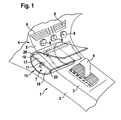
- FIG. 1 shows the center console 1 of a passenger car, with a located between the front seats console section 2, which has a substantially horizontally disposed upper surface 3 and with a front of the console section 2 adjoining console section 4, one from the upper surface 3, starting obliquely upward directed upper surface 5 has.
- a selector lever 6 of an automatic transmission In the area of the upper surface 3 of the console section 2 is a selector lever 6 of an automatic transmission.
- the console section 4 receives, adjacent to the console section 2, the storage space 7 according to the invention. Above the storage space 7, thus on the side facing away from the console section 2 side of the storage space 7, actuating buttons 8, for example, arranged for an internal ventilation system of the vehicle.
- the console section 4 air outlet slots 9.
- the storage space 7 is formed by the interior of a hollow cylinder 10, the axis 11 is arranged horizontally. By means not shown parallel to each other and arranged perpendicular to the axis 11 ends of the hollow cylinder 10 is closed.
- the stationary, thus non-rotatably mounted in the center console 1 hollow cylinder 10 has above the axis 11 to a radial opening 12, such that this opening 12 through a correspondingly formed adjacent opening 13 in the upper surface 5 of the console section 4, between the console section 2 and the operating buttons 8 is arranged, is accessible.
- This opening 13 can be closed by means of a flap 15 pivotable about an axis 14. This flap 15 is illustrated in its opening 13 releasing position with a solid line and in its opening 13 covering position with dotted line.
- a dividing element 16 is arranged, that the interior of the hollow cylinder 10 into two partial storage spaces - partial storage space 17 and partial storage space 18 - divided.
- the dividing element 16 is rotatable about the axis 14 of the hollow cylinder 10.
- the wall sections 19 of the dividing element 16 extend radially as far as the hollow cylinder 10 and axially as far as the ends of the hollow cylinder 10.
- the partition member 16 is formed so that the two wall portions 19 are plate-shaped and enclose an angle of 180 °. As a result, the two partial storage spaces 17 and 18 are substantially the same size.
- the radial opening 13 has a large length-width ratio, for example, such of at least 2: 1, at most 5: 1 and it is in particular the opening 12, with respect to its longitudinal extent, arranged parallel to the axis 11 of the hollow cylinder 10.
- the length of the radial opening 12 corresponds to the length of the hollow cylinder 10.
- the dividing element 16 is provided in the region of its hollow cylinder 10 facing end portions with the gaps between the hollow cylinder 10 and dividing element 16 bridging stripping means 20, in particular rubber lips, which are arranged leading in the direction illustrated by the arrow A direction of rotation of the dividing element 16.
- the dividing element 16 is pivoted manually or by motor, in particular by an electric motor, by rotating the axis 14 fixedly connected to the dividing element 16.
Landscapes
- Engineering & Computer Science (AREA)
- Mechanical Engineering (AREA)
- Vehicle Step Arrangements And Article Storage (AREA)
Abstract
Description
- Die Erfindung betrifft ein Kraftfahrzeug-Innenverkleidungsteil mit einem Stauraum. Bei dem Kraftfahrzeug-Innenverkleidungsteil handelt es sich z. B. um eine Instrumententafel, einen Handschuhkasten oder eine Mittelkonsole.
- Insassen von Kraftfahrzeugen, insbesondere von Personenkraftwagen, erwarten im Innenraum des Fahrzeugs ausreichend Stauraum, beispielsweise um kleinere Utensilien dort ablegen zu können. Hierbei ist es von Vorteil, wenn unterschiedliche Teilstauräume gebildet sind, so dass die Utensilien separat aufbewahrt werden können.
- Aus der
DE 10 2004 063 138 A1 ist ein Kraftfahrzeug-Innenverkleidungsteil mit einem Stauraum bekannt, wobei in dem Innenverkleidungsteil mehrere Staufächer um eine gemeinsame Achse drehbar angeordnet sind. Die Staufächer bleiben bei Drehung um die Achse in einer horizontalen Position. Zum bewerkstelligen dieser komplizierten Bewegung ist einerseits eine Lagerung der diversen Staufächer in einem gemeinsamen drehbaren Lagerteil erforderlich, ferner die drehbare Lagerung des einzelnen Staufachs im Lagerteil. Bei einer Vielzahl von Staufächern sind nur die dem Fahrzeuginsassen zugewandten Staufächer zugänglich, während die anderen Staufächer vom Innenverkleidungsteil, insbesondere einer Instrumententafel abgedeckt sind. - Nachteilig ist bei dieser Gestaltung der hohe Konstruktions-, Fertigungs- und Montageaufwand zur Schaffung des Stauraums im Kraftfahrzeug-Innenverkleidungsteil. Abgesehen hiervon ist eine große Öffnung notwendig, um den Zugang zu den dem Insassen zugewandten Staufächern zu ermöglichen.
- In der
DE 20 2005 005 226 U1 ist eine Ablageschale zur Verwendung bei einem Kraftfahrzeug beschrieben. Sie weist mindestens zwei aneinander angrenzende, sich zu der kreisförmigen, drehbaren Ablageschale ergänzende, etwa halbkreisförmige, nach oben offene Schalenbereiche auf. Jeweils die Öffnung eines Schalenbereiches ist in der Gebrauchslage zugänglich, während die Öffnung des zweiten Schalenbereichs durch Wandungsteile oder Verkleidungsteile abgedeckt ist. Ein derart gebildeter Stauraum hat nur eine geringe Tiefe und es ist dem Fahrzeuginsasse der kreissektorförmige Teilstauraum zugewandt, mit dessen recht großer axialen Öffnung. Ein solches Einbauteil ist aufgrund dessen konstruktiver Gestaltung nicht geeignet, in Bereichen des Fahrzeugs verwendet zu werden, in denen nur Platz für eine relativ kleine Öffnung zum Stauraum bereitgestellt werden kann. - Aufgabe der vorliegenden Erfindung ist es, ein Kraftfahrzeug-Innenverkleidungsteil mit einem Stauraum zu schaffen, bei dem der zur Verfügung stehende Stauraum größer ist als der Zugriffsbereich, somit die Öffnung zum Stauraum. Es soll insbesondere ein Stauraum auch dort im Fahrzeug angeordnet werden können, der unterhalb der Zugriffsmöglichkeit liegt, womit ein Stauraum geschaffen werden kann, der üblicherweise nicht im Fahrzeug zu nutzen ist.
- Zur Lösung dieser Aufgabe schlägt die Erfindung ein Kraftfahrzeug-Innenverkleidungsteil mit einem Stauraum vor, wobei der Stauraum durch das Innere eines Hohlzylinders gebildet ist, dessen Achse waagerecht angeordnet ist, wobei die Enden des Hohlzylinders geschlossen sind und der Hohlzylinder oberhalb dessen Achse eine radiale Öffnung aufweist, wobei innerhalb des Hohlzylinders ein Unterteilungselement angeordnet ist, das das Innere des Hohlzylinders in mindestens zwei Teilstauräume unterteilt, wobei das Unterteilungselement um die Achse des Hohlzylinders drehbar ist, und Wandungsabschnitte des Unterteilungselements radial bis zum Hohlzylinder und axial bis zu den Enden des Hohlzylinders reichen.
- Je nach Gestaltung des drehbaren, im Hohlzylinder gelagerten Unterteilungselements lässt sich eine mehrfache Unterteilung des im Hohlzylinder gebildeten Stauraums in Teilstauräume erreichen. Vorzugsweise ist das Unterteilungselement so gestaltet, dass zwei Teilstauräume gebildet werden, die im Wesentlichen gleich groß sind. In diesem Fall ist das Unterteilungselement bevorzugt so ausgebildet, dass die beiden Wandungsabschnitte miteinander einen Winkel von 180° einschließen. Bei waagerecht angeordnetem Unterteilungselement ist somit in diesem Fall ein oberer Teilstauraum und ein unterer Teilstauraum gebildet, die exakt übereinander liegen. Da der Hohlkörper oberhalb dessen Achse die radiale Öffnung aufweist, ist in diesem Fall nur der obere Teilstauraum zugänglich. In dieser Position können durch die Öffnung im Hohlzylinder Utensilien in den diese Öffnung zugewandten Teilstauraum eingelegt bzw. aus diesem Teilstauraum entnommen werden. Ist es gewünscht, Utensilien aus dem unteren Teilstauraum zu entnehmen, wird das Unterteilungselement gedreht, bei zwei identischen Teilstauräumen um 180°, so dass nunmehr die im jetzt oberen Teilstauraum befindlichen Utensilien durch die radiale Öffnung im Hohlzylinder ergriffen werden können, während die anderen Utensilien, die sich zuvor im oberen Bereich des Hohlzylinders befanden, nunmehr sich im unteren Bereich des Hohlzylinders befinden.
- Die Erfindung schafft bei einer Kraftfahrzeug-Innenverkleidungsteil einen baulich einfach gestalteten Stauraum, der funktionell ist und überdies es ermöglicht, bei oberhalb dessen Achse liegender radialer Öffnung in der Tiefe einen relativ großen Stauraum zu schaffen.
- Das Verschwenken des Unterteilungselements kann manuell oder mittels eines Antriebs, insbesondere eines elektrischen Antriebs erfolgen. Hierzu weist das Unterteilungselement vorzugsweise eine zentrale Welle auf, die angetrieben wird.
- Von besonderem Vorteil ist es, wenn die radiale Öffnung des Hohlzylinders ein großes Längen-Breiten-Verhältnis aufweist, wobei die Öffnung, bezogen auf ihre Längserstreckung, parallel zur Achse des Hohlzylinders angeordnet ist. Die Länge der radialen Öffnung entspricht zweckmäßig der Länge des Hohlzylinders. Hierdurch ist eine Öffnung im Hohlzylinder gebildet, die sich über die ganze Länge des Hohlzylinders erstreckt. Diese Gestaltung begünstigt das Einlegen von Utensilien in den jeweils oben liegenden Teilstauraum bzw. des Entnehmen der Utensilien aus diesem. Insbesondere beträgt das Längen-Breiten-Verhältnis der radialen Öffnung des Hohlzylinders mindestens 2:1, maximal 5:1.
- Das Kraftfahrzeug-Innenverkleidungsteil kann zusätzlich so weiter gebildet sein, dass im Hohlkörper, benachbart dessen radialer Öffnung, eine Klappe zum Verschließen der Öffnung schwenkbar oder verschieblich gelagert ist.
- Da die im jeweiligen Teilstauraum befindlichen Utensilien beim Drehen des Unterteilungselements entlang der Innenwandung des Hohlzylinders gefördert werden, insbesondere beim Fördern der Utensilien nach oben, wird es als besonders zweckmäßig angesehen, wenn das Unterteilungselement im Bereich seiner dem Hohlzylinder zugewandten Endbereiche mit die Spalte zwischen Hohlzylinder und Unterteilungselement überbrückenden Abstreifereinrichtungen versehen sind, die insbesondere in Drehrichtung des Unterteilungselements vorlaufend angeordnet sind. Hierdurch wird verhindert, dass schmale und/oder kleinteilige Utensilien in einen gewissen Spalt zwischen Unterteilungselement und Hohlzylinder gelangen und hierdurch das Unterteilungselement bezüglich des Hohlzylinders blockieren.
- Weitere Merkmale der Erfindung sind in den Unteransprüchen, der Beschreibung der Zeichnung und der Zeichnung selbst dargestellt, wobei bemerkt wird, dass alle Einzelmerkmale und alle Kombinationen von Einzelmerkmalen weitere erfinderische Ausgestaltungen darstellen.
- Eine bevorzugte Ausführungsform ist nachfolgend unter Hinweis auf die Zeichnung näher erläutert. Es zeigt:
- Figur 1
- eine räumliche Ansicht, schräg von oben und hinten gesehen, eines Kraftfahrzeug-Innenverkleidungsteils, das als Mittelkonsole eines Personenkraftwagens ausgebildet ist, mit dem erfindungsgemäßen Stauraum,
- Figur 2
- einen Schnitt durch den Stauraum, senkrecht zur Achse des Hohlzylinders geschnitten, wobei Bereiche der Mittelkonsole mitveranschaulicht - gleichfalls geschnitten - sind.
-
Figur 1 zeigt die Mittelkonsole 1 eines Personenkraftwagens, mit einem zwischen den Frontsitzen befindlichen Konsolenabschnitt 2, der eine im Wesentlichen horizontal angeordnete obere Fläche 3 besitzt sowie mit einem sich vorne an den Konsolenabschnitt 2 anschließenden Konsolenabschnitt 4, der eine von der oberen Fläche 3 ausgehend schräg nach oben gerichtete obere Fläche 5 aufweist. Im Bereich der oberen Fläche 3 des Konsolenabschnitts 2 befindet sich ein Wählhebel 6 eines Automatikgetriebes. Der Konsolenabschnitt 4 nimmt, angrenzend an den Konsolenabschnitt 2, den erfindungsgemäßen Stauraum 7 auf. Oberhalb des Stauraums 7, somit auf der dem Konsolenabschnitt 2 abgewandten Seite des Stauraums 7, sind Betätigungsknöpfe 8, beispielsweise für ein Innenbelüftungssystem des Fahrzeugs angeordnet. Darüber weist der Konsolenabschnitt 4 Luftaustrittsschlitze 9 auf. - Wie insbesondere der Darstellung der
Figur 2 zu entnehmen ist, ist der Stauraum 7 durch das Innere eines Hohlzylinders 10 gebildet, dessen Achse 11 waagerecht angeordnet ist. Mittels nicht gezeigter parallel zueinander und senkrecht zur Achse 11 angeordneter Enden ist der Hohlzylinder 10 geschlossen. Der stationär, somit nicht drehbar in der Mittelkonsole 1 gelagerte Hohlzylinder 10 weist oberhalb dessen Achse 11 eine radiale Öffnung 12 auf, derart, dass diese Öffnung 12 durch eine entsprechend ausgebildete benachbarte Öffnung 13 in der oberen Fläche 5 des Konsolenabschnitts 4, die zwischen dem Konsolenabschnitt 2 und den Betätigungsknöpfen 8 angeordnet ist, zugänglich ist. Diese Öffnung 13 ist mittels eine um eine Achse 14 schwenkbaren Klappe 15 verschließbar. Diese Klappe 15 ist in ihrer die Öffnung 13 freigebenden Stellung mit durchgezogener Linie und in ihrer die Öffnung 13 abdeckenden Position mit strichlierter Linie veranschaulicht. - Innerhalb des Hohlzylinders 10 ist ein Unterteilungselement 16 angeordnet, dass das Innere des Hohlzylinders 10 in zwei Teilstauräume - Teilstauraum 17 und Teilstauraum 18 - unterteilt. Das Unterteilungselement 16 ist um die Achse 14 des Hohlzylinders 10 drehbar. Die Wandungsabschnitte 19 des Unterteilungselements 16 reichen radial bis zum Hohlzylinder 10 und axial bis zu den Enden des Hohlzylinders 10.
- Das Unterteilungselement 16 ist so ausgebildet, dass die beiden Wandungsabschnitte 19 plattenförmig gestaltet sind und einen Winkel von 180° einschließen. Demzufolge sind die beiden Teilstauräume 17 bzw. 18 im Wesentlichen gleich groß.
- Die radiale Öffnung 13 weist ein großes Längen-Breiten-Verhältnis auf, beispielsweise ein solches von mindestens 2:1, maximal 5:1 und es ist insbesondere die Öffnung 12, bezogen auf ihre Längserstreckung, parallel zur Achse 11 des Hohlzylinders 10 angeordnet. Die Länge der radialen Öffnung 12 entspricht der Länge des Hohlzylinders 10.
- Das Unterteilungselement 16 ist im Bereich seiner dem Hohlzylinder 10 zugewandten Endbereiche mit die Spalte zwischen Hohlzylinder 10 und Unterteilungselement 16 überbrückenden Abstreifeinrichtungen 20, insbesondere Gummilippen versehen, die in der durch den Pfeil A veranschaulichten Drehrichtung des Unterteilungselements 16 vorlaufend angeordnet sind.
- Angetrieben, d. h. verschwenkt wird das Unterteilungselement 16 durch Drehen der fest mit dem Unterteilungselement 16 verbundenen Achse 14 manuell oder motorisch, insbesondere elektromotorisch.
- Beispielsweise in der Ausgangsstellung, wie sie in
Figur 2 gezeigt ist, können über die Öffnung 13 in der Mittelkonsole Gegenstände bzw. Utensilien in den zugänglichen Teilstauraum 17 eingelegt werden. Durch Schwenken des Unterteilungselements 16 um 180° in Richtung des Pfeils A wird dieser Teilstauraum 17 mit nach unten geschwenkt und der bis dahin unten befindliche Teilstauraum 18 nach oben geschwenkt, so dass in diesen nun oberen Teilstauraum Gegenstände bzw. Utensilien durch die Öffnung 13 in der Mittelkonsole 1 eingelegt bzw. durch die Öffnung 13 aus diesem Teilstauraum entnommen werden können. Durch weiteres Schwenken des Unterteilungselements 16 um 180° kommt der Teilstauraum 17 wieder oben zu liegen. Die Abstreifeinrichtungen 20 verhindern, dass Gegenstände bzw. Utensilien, die eine geringe Dicke aufweisen, beispielsweise Blätter, in den zwischen dem Unterteilungselement 16 und dem Hohlzylinder 10 gebildeten geringen Spalt gelangen können und damit die Funktionsfähigkeit der beschriebenen Einrichtung beeinträchtigen. -
- Mittelkonsole
- 1
- Konsolenabschnitt
- 2
- obere Fläche
- 3
- Konsolenabschnitt
- 4
- obere Fläche
- 5
- Wählhebel
- 6
- Stauraum
- 7
- Betätigungsknopf
- 8
- Luftaustrittsschlitz
- 9
- Hohlzylinder
- 10
- Achse
- 11
- radiale Öffnung
- 12
- Öffnung Konsole
- 13
- Achse
- 14
- Klappe
- 15
- Unterteilungselement
- 16
- Teilstauraum
- 17
- Teilstauraum
- 18
- Wandungsabschnitt
- 19
- Abstreifeinrichtung
- 20
- Drehrichtung
- A
Claims (10)
- Kraftfahrzeug-Innenverkleidungsteil (1) mit einem Stauraum (7), wobei der Stauraum (7) durch das Innere eines Hohlzylinders (10) gebildet ist, dessen Achse (11) waagerecht angeordnet ist, wobei die Enden des Hohlzylinders (10) geschlossen sind und der Hohlzylinder (10) oberhalb dessen Achse (11) eine radiale Öffnung (12) aufweist, wobei innerhalb des Hohlzylinders (10) ein Unterteilungselement (16) angeordnet ist, das das Innere des Hohlzylinders (10) in mindestens zwei Teilstauräume (17, 18) unterteilt, wobei das Unterteilungselement (16) um die Achse (11) des Hohlzylinders (10) drehbar ist, und Wandungsabschnitte (19) des Unterteilungselements (16) radial bis zum Hohlzylinder (10) und axial bis zu den Enden des Hohlzylinders (10) reichen.
- Verkleidungsteil nach Anspruch 1, wobei der jeweilige Wandungsabschnitt (19) plattenförmig ausgebildet ist.
- Verkleidungsteil nach Anspruch 1 oder 2, wobei das Unterteilungselement (16) zwei Wandungsabschnitte (19) aufweist, die den Stauraum (7) des Hohlzylinders (10) in zwei gleich große Teilstauräume (17, 18) unterteilen.
- Verkleidungsteil nach Anspruch 3, wobei die beiden Wandungsabschnitte (19) miteinander einen Winkel von 180° einschließen.
- Verkleidungsteil nach einem der Ansprüche 1 bis 4, wobei das Unterteilungselement (16) eine zentrale Welle (11) aufweist, die manuell oder mittels eines elektrischen Antriebs antreibbar ist.
- Verkleidungsteil nach einem der Ansprüche 1 bis 5, wobei die radiale Öffnung (12) des Hohlzylinders (10) ein großes Längen-Breiten-Verhältnis aufweist, wobei die Öffnung (12), bezogen auf ihre Längserstreckung, parallel zur Achse (11) des Hohlzylinders (10) angeordnet ist.
- Verkleidungsteil nach Anspruch 6, wobei die Länge der radialen Öffnung (12) der Länge des Hohlzylinders (10) entspricht.
- Verkleidungsteil nach Anspruch 6 oder 7, wobei das Längen-Breiten-Verhältnis mindestens 2:1, maximal 5:1 ist.
- Verkleidungsteil nach einem der Ansprüche 1 bis 8, wobei in den Hohlzylinder (10), benachbart dessen radialer Öffnung (12), eine Klappe (15) zum Abdecken der Öffnung (12) schwenkbar oder verschieblich gelagert ist.
- Verkleidungsteil nach einem der Ansprüche 1 bis 9, wobei das Unterteilungselement (16) im Bereich seiner dem Hohlzylinder (10) zugewandten Endbereiche mit die Spalte zwischen Hohlzylinder (10) und Unterteilungselement (16) überbrückenden Abstreifeinrichtungen (20) versehen ist, die insbesondere in Drehrichtung (A) des Unterteilungselements (16) vorlaufend angeordnet sind.
Applications Claiming Priority (1)
| Application Number | Priority Date | Filing Date | Title |
|---|---|---|---|
| DE102007042134A DE102007042134A1 (de) | 2007-09-05 | 2007-09-05 | Kraftfahrzeug-Innenverkleidungsteil mit einem Stauraum |
Publications (3)
| Publication Number | Publication Date |
|---|---|
| EP2033844A2 true EP2033844A2 (de) | 2009-03-11 |
| EP2033844A3 EP2033844A3 (de) | 2011-06-08 |
| EP2033844B1 EP2033844B1 (de) | 2012-08-15 |
Family
ID=40227760
Family Applications (1)
| Application Number | Title | Priority Date | Filing Date |
|---|---|---|---|
| EP20080011523 Not-in-force EP2033844B1 (de) | 2007-09-05 | 2008-06-25 | Kraftfahrzeug-Innenverkleidungsteil mit einem Stauraum |
Country Status (2)
| Country | Link |
|---|---|
| EP (1) | EP2033844B1 (de) |
| DE (1) | DE102007042134A1 (de) |
Cited By (2)
| Publication number | Priority date | Publication date | Assignee | Title |
|---|---|---|---|---|
| CN107585108A (zh) * | 2016-07-07 | 2018-01-16 | 福特全球技术公司 | 具有可定制次级舱的车辆的可旋转中央控制台舱 |
| FR3072627A1 (fr) * | 2017-10-20 | 2019-04-26 | Psa Automobiles Sa | Dispositif de rangement pour vehicule automobile a receptacle rotatif. |
Citations (2)
| Publication number | Priority date | Publication date | Assignee | Title |
|---|---|---|---|---|
| DE202005005226U1 (de) | 2005-03-31 | 2005-06-02 | Sarnamotive Paulmann & Crone Gmbh | Kraftfahrzeugausstattungsteil, insbesondere Ablageschale |
| DE102004063138A1 (de) | 2004-12-22 | 2006-07-06 | Faurecia Innenraum Systeme Gmbh | Kraftfahrzeug-Innenverkleidungsteil mit einem Stauraum |
Family Cites Families (5)
| Publication number | Priority date | Publication date | Assignee | Title |
|---|---|---|---|---|
| JPH0648237A (ja) * | 1992-07-31 | 1994-02-22 | Kanto Auto Works Ltd | 多目的機能を備えた回転式カップホルダ |
| GB2293150A (en) * | 1994-09-17 | 1996-03-20 | Ford Motor Co | A stowage bin |
| US5823599A (en) * | 1995-09-06 | 1998-10-20 | Textron Automotive Company Inc. | Mechanized floor console |
| FR2810936B1 (fr) * | 2000-06-29 | 2002-10-11 | Peugeot Citroen Automobiles Sa | Boite de rangement pour l'amenagement de l'habitacle d'un vehicule automobile, notamment du type boite a gants |
| FR2850329B1 (fr) * | 2003-01-27 | 2006-03-03 | Renault Sa | Dispositif de rangement multifonction pour vehicule automobile |
-
2007
- 2007-09-05 DE DE102007042134A patent/DE102007042134A1/de not_active Withdrawn
-
2008
- 2008-06-25 EP EP20080011523 patent/EP2033844B1/de not_active Not-in-force
Patent Citations (2)
| Publication number | Priority date | Publication date | Assignee | Title |
|---|---|---|---|---|
| DE102004063138A1 (de) | 2004-12-22 | 2006-07-06 | Faurecia Innenraum Systeme Gmbh | Kraftfahrzeug-Innenverkleidungsteil mit einem Stauraum |
| DE202005005226U1 (de) | 2005-03-31 | 2005-06-02 | Sarnamotive Paulmann & Crone Gmbh | Kraftfahrzeugausstattungsteil, insbesondere Ablageschale |
Cited By (2)
| Publication number | Priority date | Publication date | Assignee | Title |
|---|---|---|---|---|
| CN107585108A (zh) * | 2016-07-07 | 2018-01-16 | 福特全球技术公司 | 具有可定制次级舱的车辆的可旋转中央控制台舱 |
| FR3072627A1 (fr) * | 2017-10-20 | 2019-04-26 | Psa Automobiles Sa | Dispositif de rangement pour vehicule automobile a receptacle rotatif. |
Also Published As
| Publication number | Publication date |
|---|---|
| DE102007042134A1 (de) | 2009-03-12 |
| EP2033844A3 (de) | 2011-06-08 |
| EP2033844B1 (de) | 2012-08-15 |
Similar Documents
| Publication | Publication Date | Title |
|---|---|---|
| EP2773527B1 (de) | Mittelkonsole | |
| DE102017206720B4 (de) | Fahrzeugkonsole mit einer verstellbaren Armauflage | |
| DE102014219081A1 (de) | Luftausströmeranordnung | |
| EP3546258A1 (de) | Luftausströmer | |
| DE102010039821B4 (de) | Behälter mit geteiltem Deckel | |
| DE19936597C2 (de) | Fahrzeug, insbesondere Personenkraftwagen | |
| DE102006056381A1 (de) | Fahrzeug mit einer Fußraum-Gepäckbox | |
| DE10335046A1 (de) | Fahrzeug | |
| DE102008036005A1 (de) | Kraftfahrzeug | |
| DE20213439U1 (de) | Kühlschrank, Kühlschrankregalmontageelement und Rückhalteelement für Gegenstände | |
| DE202008008827U1 (de) | Luftdüse | |
| DE102015206841A1 (de) | Luftausströmer für eine Heizungs- und Belüftungs- oder Klimaanlage eines Kraftfahrzeugs | |
| EP2033844B1 (de) | Kraftfahrzeug-Innenverkleidungsteil mit einem Stauraum | |
| DE102017126766A1 (de) | Fahrzeugkomponente | |
| DE112008004018B4 (de) | Armlehne für Kraftfahrzeug | |
| WO2001008912A1 (de) | Luftausströmer mit lamellen | |
| DE102012010337A1 (de) | Anordnung eines Karosserieteils und eines Behältersbei einem Kraftfahrzeug | |
| DE102017100935B4 (de) | Verriegelungsmechanismus für einen Deckel eines Ablagefachs eines Kraftfahrzeugs | |
| DE202015106878U1 (de) | Luftausströmer für Heizungs- und Belüftungs- oder Klimaanlagen von Kraftfahrzeugen | |
| DE102007026611A1 (de) | Gebläse für ein Kraftfahrzeug | |
| DE102007042668B4 (de) | Mittelkonsole für ein Kraftfahrzeug | |
| EP1681205B1 (de) | Handschuhkasten in einem Kraftfahrzeug | |
| EP1817206A1 (de) | Handschuhfach für einen kraftwagen | |
| DE102014226473B4 (de) | Ablagefach, Mittelkonsole eines Fahrzeugs sowie Fahrzeug mit einem derartigen Ablagefach | |
| DE102005036624A1 (de) | Bedieneinheit für ein Kraftfahrzeug |
Legal Events
| Date | Code | Title | Description |
|---|---|---|---|
| PUAI | Public reference made under article 153(3) epc to a published international application that has entered the european phase |
Free format text: ORIGINAL CODE: 0009012 |
|
| AK | Designated contracting states |
Kind code of ref document: A2 Designated state(s): AT BE BG CH CY CZ DE DK EE ES FI FR GB GR HR HU IE IS IT LI LT LU LV MC MT NL NO PL PT RO SE SI SK TR |
|
| AX | Request for extension of the european patent |
Extension state: AL BA MK RS |
|
| PUAL | Search report despatched |
Free format text: ORIGINAL CODE: 0009013 |
|
| AK | Designated contracting states |
Kind code of ref document: A3 Designated state(s): AT BE BG CH CY CZ DE DK EE ES FI FR GB GR HR HU IE IS IT LI LT LU LV MC MT NL NO PL PT RO SE SI SK TR |
|
| AX | Request for extension of the european patent |
Extension state: AL BA MK RS |
|
| RAP1 | Party data changed (applicant data changed or rights of an application transferred) |
Owner name: GM GLOBAL TECHNOLOGY OPERATIONS LLC |
|
| 17P | Request for examination filed |
Effective date: 20111208 |
|
| RIC1 | Information provided on ipc code assigned before grant |
Ipc: B60R 7/06 20060101AFI20111222BHEP Ipc: B60R 11/00 20060101ALN20111222BHEP |
|
| GRAP | Despatch of communication of intention to grant a patent |
Free format text: ORIGINAL CODE: EPIDOSNIGR1 |
|
| AKX | Designation fees paid |
Designated state(s): AT BE BG CH CY CZ DE DK EE ES FI FR GB GR HR HU IE IS IT LI LT LU LV MC MT NL NO PL PT RO SE SI SK TR |
|
| RIC1 | Information provided on ipc code assigned before grant |
Ipc: B60R 7/06 20060101AFI20120206BHEP Ipc: B60R 11/00 20060101ALN20120206BHEP |
|
| GRAS | Grant fee paid |
Free format text: ORIGINAL CODE: EPIDOSNIGR3 |
|
| GRAA | (expected) grant |
Free format text: ORIGINAL CODE: 0009210 |
|
| AK | Designated contracting states |
Kind code of ref document: B1 Designated state(s): AT BE BG CH CY CZ DE DK EE ES FI FR GB GR HR HU IE IS IT LI LT LU LV MC MT NL NO PL PT RO SE SI SK TR |
|
| REG | Reference to a national code |
Ref country code: AT Ref legal event code: REF Ref document number: 570635 Country of ref document: AT Kind code of ref document: T Effective date: 20120815 Ref country code: GB Ref legal event code: FG4D Free format text: NOT ENGLISH Ref country code: CH Ref legal event code: EP |
|
| REG | Reference to a national code |
Ref country code: IE Ref legal event code: FG4D Free format text: LANGUAGE OF EP DOCUMENT: GERMAN |
|
| REG | Reference to a national code |
Ref country code: DE Ref legal event code: R096 Ref document number: 502008007933 Country of ref document: DE Effective date: 20121011 |
|
| REG | Reference to a national code |
Ref country code: NL Ref legal event code: VDEP Effective date: 20120815 |
|
| PG25 | Lapsed in a contracting state [announced via postgrant information from national office to epo] |
Ref country code: IS Free format text: LAPSE BECAUSE OF FAILURE TO SUBMIT A TRANSLATION OF THE DESCRIPTION OR TO PAY THE FEE WITHIN THE PRESCRIBED TIME-LIMIT Effective date: 20121215 Ref country code: CY Free format text: LAPSE BECAUSE OF FAILURE TO SUBMIT A TRANSLATION OF THE DESCRIPTION OR TO PAY THE FEE WITHIN THE PRESCRIBED TIME-LIMIT Effective date: 20120815 Ref country code: LT Free format text: LAPSE BECAUSE OF FAILURE TO SUBMIT A TRANSLATION OF THE DESCRIPTION OR TO PAY THE FEE WITHIN THE PRESCRIBED TIME-LIMIT Effective date: 20120815 Ref country code: NO Free format text: LAPSE BECAUSE OF FAILURE TO SUBMIT A TRANSLATION OF THE DESCRIPTION OR TO PAY THE FEE WITHIN THE PRESCRIBED TIME-LIMIT Effective date: 20121115 Ref country code: FI Free format text: LAPSE BECAUSE OF FAILURE TO SUBMIT A TRANSLATION OF THE DESCRIPTION OR TO PAY THE FEE WITHIN THE PRESCRIBED TIME-LIMIT Effective date: 20120815 Ref country code: HR Free format text: LAPSE BECAUSE OF FAILURE TO SUBMIT A TRANSLATION OF THE DESCRIPTION OR TO PAY THE FEE WITHIN THE PRESCRIBED TIME-LIMIT Effective date: 20120815 |
|
| PG25 | Lapsed in a contracting state [announced via postgrant information from national office to epo] |
Ref country code: GR Free format text: LAPSE BECAUSE OF FAILURE TO SUBMIT A TRANSLATION OF THE DESCRIPTION OR TO PAY THE FEE WITHIN THE PRESCRIBED TIME-LIMIT Effective date: 20121116 Ref country code: PL Free format text: LAPSE BECAUSE OF FAILURE TO SUBMIT A TRANSLATION OF THE DESCRIPTION OR TO PAY THE FEE WITHIN THE PRESCRIBED TIME-LIMIT Effective date: 20120815 Ref country code: SE Free format text: LAPSE BECAUSE OF FAILURE TO SUBMIT A TRANSLATION OF THE DESCRIPTION OR TO PAY THE FEE WITHIN THE PRESCRIBED TIME-LIMIT Effective date: 20120815 Ref country code: PT Free format text: LAPSE BECAUSE OF FAILURE TO SUBMIT A TRANSLATION OF THE DESCRIPTION OR TO PAY THE FEE WITHIN THE PRESCRIBED TIME-LIMIT Effective date: 20121217 Ref country code: SI Free format text: LAPSE BECAUSE OF FAILURE TO SUBMIT A TRANSLATION OF THE DESCRIPTION OR TO PAY THE FEE WITHIN THE PRESCRIBED TIME-LIMIT Effective date: 20120815 Ref country code: LV Free format text: LAPSE BECAUSE OF FAILURE TO SUBMIT A TRANSLATION OF THE DESCRIPTION OR TO PAY THE FEE WITHIN THE PRESCRIBED TIME-LIMIT Effective date: 20120815 |
|
| PG25 | Lapsed in a contracting state [announced via postgrant information from national office to epo] |
Ref country code: NL Free format text: LAPSE BECAUSE OF FAILURE TO SUBMIT A TRANSLATION OF THE DESCRIPTION OR TO PAY THE FEE WITHIN THE PRESCRIBED TIME-LIMIT Effective date: 20120815 |
|
| PG25 | Lapsed in a contracting state [announced via postgrant information from national office to epo] |
Ref country code: ES Free format text: LAPSE BECAUSE OF FAILURE TO SUBMIT A TRANSLATION OF THE DESCRIPTION OR TO PAY THE FEE WITHIN THE PRESCRIBED TIME-LIMIT Effective date: 20121126 Ref country code: RO Free format text: LAPSE BECAUSE OF FAILURE TO SUBMIT A TRANSLATION OF THE DESCRIPTION OR TO PAY THE FEE WITHIN THE PRESCRIBED TIME-LIMIT Effective date: 20120815 Ref country code: CZ Free format text: LAPSE BECAUSE OF FAILURE TO SUBMIT A TRANSLATION OF THE DESCRIPTION OR TO PAY THE FEE WITHIN THE PRESCRIBED TIME-LIMIT Effective date: 20120815 Ref country code: EE Free format text: LAPSE BECAUSE OF FAILURE TO SUBMIT A TRANSLATION OF THE DESCRIPTION OR TO PAY THE FEE WITHIN THE PRESCRIBED TIME-LIMIT Effective date: 20120815 Ref country code: DK Free format text: LAPSE BECAUSE OF FAILURE TO SUBMIT A TRANSLATION OF THE DESCRIPTION OR TO PAY THE FEE WITHIN THE PRESCRIBED TIME-LIMIT Effective date: 20120815 |
|
| PG25 | Lapsed in a contracting state [announced via postgrant information from national office to epo] |
Ref country code: IT Free format text: LAPSE BECAUSE OF FAILURE TO SUBMIT A TRANSLATION OF THE DESCRIPTION OR TO PAY THE FEE WITHIN THE PRESCRIBED TIME-LIMIT Effective date: 20120815 Ref country code: SK Free format text: LAPSE BECAUSE OF FAILURE TO SUBMIT A TRANSLATION OF THE DESCRIPTION OR TO PAY THE FEE WITHIN THE PRESCRIBED TIME-LIMIT Effective date: 20120815 |
|
| PLBE | No opposition filed within time limit |
Free format text: ORIGINAL CODE: 0009261 |
|
| STAA | Information on the status of an ep patent application or granted ep patent |
Free format text: STATUS: NO OPPOSITION FILED WITHIN TIME LIMIT |
|
| 26N | No opposition filed |
Effective date: 20130516 |
|
| PG25 | Lapsed in a contracting state [announced via postgrant information from national office to epo] |
Ref country code: BG Free format text: LAPSE BECAUSE OF FAILURE TO SUBMIT A TRANSLATION OF THE DESCRIPTION OR TO PAY THE FEE WITHIN THE PRESCRIBED TIME-LIMIT Effective date: 20121115 |
|
| REG | Reference to a national code |
Ref country code: DE Ref legal event code: R097 Ref document number: 502008007933 Country of ref document: DE Effective date: 20130516 |
|
| BERE | Be: lapsed |
Owner name: GM GLOBAL TECHNOLOGY OPERATIONS LLC Effective date: 20130630 |
|
| PG25 | Lapsed in a contracting state [announced via postgrant information from national office to epo] |
Ref country code: MC Free format text: LAPSE BECAUSE OF FAILURE TO SUBMIT A TRANSLATION OF THE DESCRIPTION OR TO PAY THE FEE WITHIN THE PRESCRIBED TIME-LIMIT Effective date: 20120815 |
|
| REG | Reference to a national code |
Ref country code: CH Ref legal event code: PL |
|
| REG | Reference to a national code |
Ref country code: IE Ref legal event code: MM4A |
|
| PG25 | Lapsed in a contracting state [announced via postgrant information from national office to epo] |
Ref country code: BE Free format text: LAPSE BECAUSE OF NON-PAYMENT OF DUE FEES Effective date: 20130630 |
|
| PG25 | Lapsed in a contracting state [announced via postgrant information from national office to epo] |
Ref country code: CH Free format text: LAPSE BECAUSE OF NON-PAYMENT OF DUE FEES Effective date: 20130630 Ref country code: LI Free format text: LAPSE BECAUSE OF NON-PAYMENT OF DUE FEES Effective date: 20130630 Ref country code: IE Free format text: LAPSE BECAUSE OF NON-PAYMENT OF DUE FEES Effective date: 20130625 |
|
| REG | Reference to a national code |
Ref country code: AT Ref legal event code: MM01 Ref document number: 570635 Country of ref document: AT Kind code of ref document: T Effective date: 20130625 |
|
| PG25 | Lapsed in a contracting state [announced via postgrant information from national office to epo] |
Ref country code: AT Free format text: LAPSE BECAUSE OF NON-PAYMENT OF DUE FEES Effective date: 20130625 |
|
| PG25 | Lapsed in a contracting state [announced via postgrant information from national office to epo] |
Ref country code: MT Free format text: LAPSE BECAUSE OF FAILURE TO SUBMIT A TRANSLATION OF THE DESCRIPTION OR TO PAY THE FEE WITHIN THE PRESCRIBED TIME-LIMIT Effective date: 20120815 |
|
| REG | Reference to a national code |
Ref country code: FR Ref legal event code: PLFP Year of fee payment: 8 |
|
| PG25 | Lapsed in a contracting state [announced via postgrant information from national office to epo] |
Ref country code: TR Free format text: LAPSE BECAUSE OF FAILURE TO SUBMIT A TRANSLATION OF THE DESCRIPTION OR TO PAY THE FEE WITHIN THE PRESCRIBED TIME-LIMIT Effective date: 20120815 |
|
| PG25 | Lapsed in a contracting state [announced via postgrant information from national office to epo] |
Ref country code: HU Free format text: LAPSE BECAUSE OF FAILURE TO SUBMIT A TRANSLATION OF THE DESCRIPTION OR TO PAY THE FEE WITHIN THE PRESCRIBED TIME-LIMIT; INVALID AB INITIO Effective date: 20080625 Ref country code: LU Free format text: LAPSE BECAUSE OF NON-PAYMENT OF DUE FEES Effective date: 20130625 |
|
| PGFP | Annual fee paid to national office [announced via postgrant information from national office to epo] |
Ref country code: DE Payment date: 20150616 Year of fee payment: 8 Ref country code: GB Payment date: 20150624 Year of fee payment: 8 |
|
| PGFP | Annual fee paid to national office [announced via postgrant information from national office to epo] |
Ref country code: FR Payment date: 20150608 Year of fee payment: 8 |
|
| REG | Reference to a national code |
Ref country code: DE Ref legal event code: R119 Ref document number: 502008007933 Country of ref document: DE |
|
| GBPC | Gb: european patent ceased through non-payment of renewal fee |
Effective date: 20160625 |
|
| REG | Reference to a national code |
Ref country code: FR Ref legal event code: ST Effective date: 20170228 |
|
| PG25 | Lapsed in a contracting state [announced via postgrant information from national office to epo] |
Ref country code: FR Free format text: LAPSE BECAUSE OF NON-PAYMENT OF DUE FEES Effective date: 20160630 Ref country code: DE Free format text: LAPSE BECAUSE OF NON-PAYMENT OF DUE FEES Effective date: 20170103 |
|
| PG25 | Lapsed in a contracting state [announced via postgrant information from national office to epo] |
Ref country code: GB Free format text: LAPSE BECAUSE OF NON-PAYMENT OF DUE FEES Effective date: 20160625 |