EP2033698B1 - Massenübertragungsvorrichtung - Google Patents
Massenübertragungsvorrichtung Download PDFInfo
- Publication number
- EP2033698B1 EP2033698B1 EP07748809.6A EP07748809A EP2033698B1 EP 2033698 B1 EP2033698 B1 EP 2033698B1 EP 07748809 A EP07748809 A EP 07748809A EP 2033698 B1 EP2033698 B1 EP 2033698B1
- Authority
- EP
- European Patent Office
- Prior art keywords
- plate
- way valve
- frame
- der
- die
- Prior art date
- Legal status (The legal status is an assumption and is not a legal conclusion. Google has not performed a legal analysis and makes no representation as to the accuracy of the status listed.)
- Not-in-force
Links
- 239000007787 solid Substances 0.000 claims description 5
- 125000006850 spacer group Chemical group 0.000 claims description 4
- 239000000463 material Substances 0.000 claims 1
- 239000007788 liquid Substances 0.000 description 19
- 230000009467 reduction Effects 0.000 description 5
- 239000002184 metal Substances 0.000 description 3
- 238000010276 construction Methods 0.000 description 2
- 125000004122 cyclic group Chemical group 0.000 description 2
- 230000000694 effects Effects 0.000 description 2
- 238000000034 method Methods 0.000 description 2
- 239000012071 phase Substances 0.000 description 2
- 230000007704 transition Effects 0.000 description 2
- 230000000712 assembly Effects 0.000 description 1
- 238000000429 assembly Methods 0.000 description 1
- 230000004888 barrier function Effects 0.000 description 1
- 230000008859 change Effects 0.000 description 1
- 238000006073 displacement reaction Methods 0.000 description 1
- 239000012530 fluid Substances 0.000 description 1
- 239000002655 kraft paper Substances 0.000 description 1
- 238000004519 manufacturing process Methods 0.000 description 1
- 238000010327 methods by industry Methods 0.000 description 1
- 239000003208 petroleum Substances 0.000 description 1
- 230000008569 process Effects 0.000 description 1
- 210000002023 somite Anatomy 0.000 description 1
- 230000005654 stationary process Effects 0.000 description 1
- 238000010025 steaming Methods 0.000 description 1
- 239000000126 substance Substances 0.000 description 1
- 239000012808 vapor phase Substances 0.000 description 1
Images


Classifications
-
- B—PERFORMING OPERATIONS; TRANSPORTING
- B01—PHYSICAL OR CHEMICAL PROCESSES OR APPARATUS IN GENERAL
- B01D—SEPARATION
- B01D3/00—Distillation or related exchange processes in which liquids are contacted with gaseous media, e.g. stripping
- B01D3/14—Fractional distillation or use of a fractionation or rectification column
- B01D3/16—Fractionating columns in which vapour bubbles through liquid
- B01D3/163—Plates with valves
-
- B—PERFORMING OPERATIONS; TRANSPORTING
- B01—PHYSICAL OR CHEMICAL PROCESSES OR APPARATUS IN GENERAL
- B01D—SEPARATION
- B01D3/00—Distillation or related exchange processes in which liquids are contacted with gaseous media, e.g. stripping
- B01D3/14—Fractional distillation or use of a fractionation or rectification column
- B01D3/16—Fractionating columns in which vapour bubbles through liquid
- B01D3/18—Fractionating columns in which vapour bubbles through liquid with horizontal bubble plates
- B01D3/20—Bubble caps; Risers for vapour; Discharge pipes for liquid
Definitions
- the invention relates to a contact device for mass transfer with a dish plate, a bubble unit, an additional plate plate, a frame which is provided at its periphery with openings, a movable two-way valve, which arranged in the form of superposed, each other by means of a spacer web connected solid plates is, connected, with a lifting and lowering limiter.
- the invention may be used in the food, chemical, petrochemical and food industries petroleum processing industry and other industries.
- a contact device for mass transfer which has a plate plate with a contact element, a frame, a movable two-way valve, a lifting and lowering limiter.
- the frame has openings at its periphery.
- the movable two-way valve is designed in the form of stacked solid plates.
- the device is equipped with an additional plate plate.
- the contact element serves as a stroke limiter of the two-way valve.
- the lower frame edge serves as Senkbegrenzer.
- the lower edges of the openings of the frame are carried out in the height of the additional (lower) plate plate.
- the contact element is designed as an inner cap with the tangentially bent plates of the bladder unit.
- the height of the vertical openings at the periphery of the frame is equal to the height of the two-way valve. In the end positions of the two-way valve one of the valve plates ensures the free-cutting of the vertical openings of the frame in equal sections ( RU2237508 C1 ).
- the shortcoming of this device is the fixed free section of the bladder unit. This results in a displacement of the working range of the device in the direction of increasing the steam consumption at low liquid loads.
- the further shortcoming of the device is its height (the dimension between the main and the additional dish plate), which causes the increase of the column height and thus the metal expense.
- the bubble unit serves as a contact element.
- the contact device for mass transfer thereby represents a totality of elements and assemblies that ensure the function of the plate in batch operation.
- the contact element ensures contact between the vapor and the liquid.
- the bubble unit is a component of the contact element at the point where the vapor is fed into the liquid.
- US 2002/163091 A1 is a contact device for mass transfer with a dish plate, a bladder unit, a movable valve, which is designed in the form of a perforated plate, with a stroke limiter in the form of arranged on the perforated plate legs and Senkbegrenzer known.
- the bladder unit serves as Senkbeskyr, the bent lower edge of the legs as a stroke limiter.
- the plate and the legs of the valve serve as a contact element.
- the contactor for mass transfer includes a bowl plate with a contact element, a frame, a movable two-way valve and a lifting and Senkbegrenzer. At the periphery of the frame openings are made.
- the movable two-way valve is designed as a stacked solid plates.
- the device is provided with an additional plate plate.
- the bladder unit serves as a stroke limiter of the two-way valve, and the lower frame edge as Senkbegrenzer.
- the lower edges of the openings of the frame are carried out in the height of the additional (lower) plate plate.
- the height of the vertical openings at the periphery of the frame is equal to the height of the two-way valve. In the end positions of the two-way valve one of the valve plates ensures the free-cutting section of the vertical openings of the frame in equal sections.
- the upper plate of the two-way valve serves as a contact element and the bladder unit is connected to the frame.
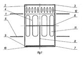
- the contact device consists of a dish plate 1, a bubble unit 2 with openings 12, a frame 4 with openings 11 and 10, an additional (lower) plate plate 5 and a two-way valve.
- the valve moves in the middle of the frame 4.
- the frame 4 consists of an upper plate 6 and a lower plate 7, which are interconnected by means of a spacer web 8.
- the bent lower edge edge 4 serves as Senkbegrenzer 9, and the bent upper edge of the bladder unit serves as a stroke limiter.
- the two-way valve moves down under the effect of its own weight and liquid weight. In the height of the plate plate 1, the speed slows down and the valve settles on the Senkbegrenzer 9 bumpless. This extends the life of the entire construction.
- the delay time for the gas supply is determined depending on the overflow time of the liquid from the dish plate 1 in the transition vessel and can be several seconds.
- the lifting force attack changes from the lower plate 7 to the upper plate 6 of the two-way valve.
- the greatest possible pressure drop is maintained and thereby also the lifting force on the upper plate 6.
- the gas (the steam) flows into the openings of the frame 4 and thereby barbotiert by the liquid.
- the opening becomes larger, the velocity of the steam flowing through the opening becomes lower.
- the two-way valve continues to rise until it reaches the fixed upper position.
- the weight of the two-way valve and the liquid column above this must be less than the force that arises as a result of the pressure drop when the pressure hits the upper plate 6.
- the time when the liquid overflows from one plate to another is called the liquid period.
- the time of the cycle which consists of the steam and the liquid period, expires.
- the subsequent cycles run in the same way.
- the proposed contact device makes it possible to carry out the mass transfer process in the gas-liquid system (vapor-liquid system) in cyclic operation at the same time changing the liquid delay simultaneously on all plates over the entire height of the column. It extends the fluid and vapor load area, increasing performance and safety, and extends the life of the entire structure.
- the use of the proposed contact device eliminates the mixing of the liquid in the adjacent contact stages and makes it possible to increase the efficiency of the mass transfer by two to three times compared to the stationary operations.
Landscapes
- Chemical & Material Sciences (AREA)
- Chemical Kinetics & Catalysis (AREA)
- Physical Or Chemical Processes And Apparatus (AREA)
- Lift Valve (AREA)
- Mechanically-Actuated Valves (AREA)
- Production Of Liquid Hydrocarbon Mixture For Refining Petroleum (AREA)
Description
- Die Erfindung bezieht sich auf eine Kontaktvorrichtung für Stoffaustausch mit einer Tellerplatte, einer Blaseneinheit, einer zusätzlichen Tellerplatte, einer Zarge, die an ihrem Umfang mit Öffnungen versehen ist, einem beweglichen Zweiwegeventil, welches in Form von übereinander angeordneten, untereinander mittels eines Distanzsteges verbundene Vollplatten ausgeführt ist, verbunden, mit einem Hub- und Senkbegrenzer.
- Darunter fallen Vorrichtungen, welche für die Durchführung von Stoffaustauschvorgängen in einem Gas (Dampf)-Flüssigkeit-System unter Bedingungen des zyklischen Betriebs (bei getrennter Bewegung von Phasen in der Kolonne) bestimmt sind. Die Erfindung kann im Nahrungsmittelsektor, in der Chemie-, der petrochemischen und der erdölverarbeitenden Industrie sowie in anderen Industriezweigen angewendet werden.
- Es ist eine Kontaktvorrichtung für Stoffaustausch bekannt, welche eine Tellerplatte mit einem Kontaktelement, eine Zarge, ein bewegliches Zweiwegeventil, einen Hub- und Senkbegrenzer aufweist. Die Zarge weist an ihrem Umfang Öffnungen auf. Das bewegliche Zweiwegeventil ist in Form von übereinander angeordneten Vollplatten ausgeführt. Dabei ist die Vorrichtung mit einer zusätzlichen Tellerplatte ausgerüstet.
- Das Kontaktelement dient als Hubbegrenzer des Zweiwegeventils. Die untere Zargenkante dient als Senkbegrenzer. Die Unterkanten der Öffnungen der Zarge sind in der Höhe der zusätzlichen (unteren) Tellerplatte ausgeführt. Außerdem ist das Kontaktelement als Innenkappe mit den tangential abgebogenen Platten der Blaseneinheit ausgeführt. Die Höhe der senkrechten Öffnungen am Umfang der Zarge ist gleich der Höhe des Zweiwegeventils. In den Endstellungen des Zweiwegeventils stellt eine der Ventilplatten die Freiquerschnittsaufteilung der senkrechten Öffnungen der Zarge in gleiche Abschnitte sicher (
RU2237508 C1 - Der Mangel dieser Vorrichtung ist der fixierte Freiquerschnitt der Blaseneinheit. Dadurch kommt eine Versetzung des Arbeitsbereichs der Vorrichtung in Richtung einer Erhöhung des Dampfverbrauchs bei geringen Flüssigkeitsbelastungen zustande. Der weitere Mangel der Vorrichtung ist ihre Höhe (das Maß zwischen der Haupt- und der zusätzlichen Tellerplatte), was die Vergrößerung der Kolonnenhöhe und somit den Metallaufwand verursacht.
- Bei der durch
RU 2237508 C1 - Durch
US 2002/163091 A1 ist eine Kontaktvorrichtung für Stoffaustausch mit einer Tellerplatte, einer Blaseneinheit, einem beweglichen Ventil, welches in Form einer perforierten Platte ausgeführt ist, mit einem Hubbegrenzer in Form von an der perforierten Platte angeordneten Beinchen und Senkbegrenzer bekannt. Die Blaseneinheit dient als Senkbegrenzer, die abgebogene untere Kante der Beinchen als Hubbegrenzer. Die Platte sowie die Beinchen des Ventils dienen als Kontaktelement. - Es ist Aufgabe der Erfindung eine Vorrichtung zu schaffen, die eine Erweiterung des Belastungsbereichs in Bezug auf Dampf, eine Senkung des Metallaufwands und eine Minderung der Höhe der Stoffaustauschvorrichtung erreicht und die Sicherheit und die Lebensdauer der Konstruktion erhöht.
- Die gestellte Aufgabe wird durch die Merkmale des Anspruchs 1 gelöst.
- Die Kontaktvorrichtung für Stoffaustausch enthält eine Tellerplatte mit einem Kontaktelement, eine Zarge, ein bewegliches Zweiwegeventil und einen Hub- und Senkbegrenzer. Am Umfang der Zarge sind Öffnungen ausgeführt. Das bewegliche Zweiwegeventil ist als übereinander aufgestellte Vollplatten ausgebildet. Dabei ist die Vorrichtung mit einer zusätzlichen Tellerplatte versehen. Die Blaseneinheit dient als Hubbegrenzer des Zweiwegeventils, und die untere Zargenkante als Senkbegrenzer. Die Unterkanten der Öffnungen der Zarge sind in der Höhe der zusätzlichen (unteren) Tellerplatte ausgeführt. Die Höhe der senkrechten Öffnungen am Umfang der Zarge ist gleich die Höhe des Zweiwegeventils. In den Endstellungen des Zweiwegeventils stellt eine der Ventilplatten die Freiquerschnittsaufteilung der senkrechten Öffnungen der Zarge in gleiche Abschnitte sicher. Die obere Platte des Zweiwegeventils dient als Kontaktelement und die Blaseneinheit ist mit der Zarge verbunden.
- Die Ursache-Wirkung-Beziehung zwischen den vorgeschlagenen Merkmalen und dem technischen Ergebnis besteht im Folgenden:
- 1. Die vorgeschlagene Kontaktvorrichtung verfügt über verfahrenstechnische Vorteile des Ventiltellers in einem stationären Prozess, und zwar: Die Minderung des Freiquerschnittes der Blaseneinheit des Kontaktelements unter einer Dampfverbrauchminderung. Somit wird der konstante Druckabfall auf dem Boden aufrechterhalten, indem die Position des Zweiwegeventils in den oberen Stellung sichergestellt ist.
- 2. Wenn das Gas (der Dampf) zum Kontaktelement unter die obere Platte des Zweiwegeventils kommt, wird der Dampfwirkdruck als eine zusätzliche Kraft verwendet, um das Ventil in der oberen Stellung zu halten.
- 3. Die Höhenminderung der Kontaktvorrichtung um 30 % ermöglicht es, den Metallaufwand für die Kolonnefertigung um 10 % zu reduzieren.
- 4. Bei einer stufenlosen Dampfsperrung bewegt sich das Ventil nach unten und mindert seine Bewegungsgeschwindigkeit in der Höhe der oberen Reihe der Öffnungen in der Zarge. Damit lässt sich das Ventil stufenlos und stoßfrei auf den Senkbegrenzer nieder. Damit wird die Lebensdauer der Konstruktion vergrößert.
- Die Erfindung wird anhand eines in den Zeichnungen schematisch dargestellten Ausführungsbeispiels näher erläutert. Es zeigen:
- Fig. 1
- die Vorrichtung in der Position, die dem Anfang der Gaszufuhr (Dampfzufuhr) entspricht,
- Fig. 2
- die Vorrichtung in der Position, die der Änderung des Hebekraftangriffes von der unteren zur oberen Platte des Zweiwegeventils entspricht und
- Fig. 3
- die Vorrichtung in der Position, die allen nachfolgenden Zeitpunkten der Gaszufuhr (Dampfzufuhr) entspricht.
- Die Kontaktvorrichtung besteht aus einer Tellerplatte 1, einer Blaseneinheit 2 mit Öffnungen 12, einer Zarge 4 mit Öffnungen 11 und 10, einer zusätzlichen (unteren) Tellerplatte 5 und einem Zweiwegeventil. Das Ventil bewegt sich in der Mitte der Zarge 4. Die Zarge 4 besteht aus einer oberen Platte 6 und einer unteren 7 Platte, die mittels eines Distanzsteges 8 miteinander verbunden sind. Die abgebogene untere Zargenkante 4 dient als Senkbegrenzer 9, und die abgebogene obere Kante der Blaseneinheit dient als Hubbegrenzer 3.
- Die Funktionsweise der Kontaktvorrichtung ist wie folgt:
- Die Gasphase (Dampfphase) während der ersten Dampfperiode bringt das Zweiwegeventil in die fixierte obere Stellung und zwar so, dass die obere Platte 6 des Zweiwegeventils die Öffnung des Kontaktelements 2 schließt. In dieser Stellung dient die obere Platte 6 des Zweiwegeventils als Ventil-Kontaktelement. Der Dampf fließt unter der oberen Platte 6 durch die Öffnungen 12 der Blaseneinheit 2 und wirkt dabei mit der Flüssigkeit zusammen, die sich im Teller befindet.
- Nach dem Abschluss der Dampfperiode bewegt sich das Zweiwegeventil unter der Wirkung von seinem eigenen Gewicht und dem Flüssigkeitsgewicht nach unten. In der Höhe der Tellerplatte 1 wird die Geschwindigkeit langsamer und das Ventil lässt sich auf den Senkbegrenzer 9 stoßfrei nieder. Dadurch wird die Lebensdauer der gesamten Konstruktion verlängert.
- Die Verzögerungszeit für die Gaszufuhr (Dampfzufuhr) wird je nach der Überlaufszeit der Flüssigkeit von der Tellerplatte 1 in den Übergangsbehälter festgelegt und kann einige Sekunden betragen.
- Am Anfang der Gaszufuhr (Dampfzufuhr) auf die untere Platte wird die untere Platte 7 des Zweiwegeventils durch die Hebekraft beansprucht, welche durch den Druckabfall bedingt ist. Unter dieser Kraftwirkung werden das Zweiwegeventil und die Flüssigkeit dahinter hochsteigen, wobei die Flüssigkeit sich im Übergangsbehälter befindet.
- Sobald die Platten 6 und 7 des Zweiwegeventils die Höhe der Öffnungen der Zarge 4 erreichen, wechselt der Hebekraftangriff von der unteren Platte 7 zur oberen Platte 6 des Zweiwegeventils. Dabei bleibt der größtmögliche Druckabfall erhalten und dadurch auch die Hebekraft auf die obere Platte 6. Das Gas (der Dampf) fließt in die Öffnungen der Zarge 4 und barbotiert dabei durch die Flüssigkeit. Wird die Öffnung größer, so wird die Geschwindigkeit des Dampfes, welcher durch die Öffnung fließt, niedriger. Somit entstehen die Bedingungen, bei denen die Flüssigkeit zum tiefer angeordneten Teller 5 fließt. Das Zweiwegeventil steigt weiter nach oben, bis es die fixierte obere Stellung erreicht. Das Gewicht des Zweiwegeventils und der Flüssigkeitssäule darüber müssen geringer als die Kraft sein, die infolge des Druckabfalls entsteht, wenn der Druck auf die obere Platte 6 trifft.
- Die Zeit, wo die Flüssigkeit von einem Teller zum anderen überströmt, wird Flüssigkeitsperiode genannt. Somit läuft die Zeit des Zyklus ab, welcher aus der Dampf- und der Flüssigkeitsperiode besteht. Die nachfolgenden Zyklen verlaufen auf die gleiche Weise.
- Die vorgeschlagene Kontaktvorrichtung ermöglicht es, den Stoffaustauschvorgang im Gas-Flüssigkeits-System (Dampf-Flüssigkeits-System) im zyklischen Betrieb beim einmaligen Wechsel der Flüssigkeitsverzögerung gleichzeitig auf allen Tellern über die gesamte Höhe der Kolonne durchzuführen. Dabei wird der Belastungsbereich in Bezug Flüssigkeit und Dampf erweitert, die Leistungsfähigkeit und die Sicherheit erhöht, und die Lebensdauer der gesamten Konstruktion verlängert.
- Der Einsatz der vorgeschlagenen Kontaktvorrichtung beseitigt die Vermischung der Flüssigkeit in den angrenzenden Kontaktstufen und ermöglicht es, die Effizienz des Stoffaustausches um das zwei- bis dreifache gegenüber den stationären Vorgängen zu steigern.
Claims (1)
- Kontaktvorrichtung für Stoffaustausch mit einer Tellerplatte (1), einer Blaseneinheit (2), einer zusätzlichen Tellerplatte (5), einer Zarge (4), die an ihrem Umfang mit Öffnungen (10, 11 und 12) versehen ist, einem beweglichen Zweiwegeventil, welches in Form von übereinander angeordneten, untereinander mittels eines Distanzsteges (8) verbundene Vollplatten (6, 7) ausgeführt ist, verbunden, mit einem Hub- (3) und Senkbegrenzer (9), wobei:- die abgebogene untere Kante der Zarge (4) als Senkbegrenzer (9) dient,- die obere Platte (6) des Zweiwegeventils in der oberen Stellung als Kontaktelement dient, und- die obere Platte (6) des Zweiwegeventils in der oberen Stellung die Öffnung des Kontaktelements (2) schließt,dadurch gekennzeichnet, dass- die Blaseneinheit (2) mit der Zarge (4) vereinigt ist, und- die abgebogene obere Kante der Blaseneinheit als Hubbegrenzer (3) dient.
Applications Claiming Priority (2)
| Application Number | Priority Date | Filing Date | Title |
|---|---|---|---|
| UAA200606612A UA81192C2 (en) | 2006-06-13 | 2006-06-13 | Mass-exchange contact device |
| PCT/UA2007/000038 WO2007145604A1 (en) | 2006-06-13 | 2007-06-07 | Mass-transfer device |
Publications (3)
| Publication Number | Publication Date |
|---|---|
| EP2033698A1 EP2033698A1 (de) | 2009-03-11 |
| EP2033698A4 EP2033698A4 (de) | 2012-03-07 |
| EP2033698B1 true EP2033698B1 (de) | 2015-10-28 |
Family
ID=38832020
Family Applications (1)
| Application Number | Title | Priority Date | Filing Date |
|---|---|---|---|
| EP07748809.6A Not-in-force EP2033698B1 (de) | 2006-06-13 | 2007-06-07 | Massenübertragungsvorrichtung |
Country Status (5)
| Country | Link |
|---|---|
| US (1) | US20090200690A1 (de) |
| EP (1) | EP2033698B1 (de) |
| EA (1) | EA013137B1 (de) |
| UA (1) | UA81192C2 (de) |
| WO (1) | WO2007145604A1 (de) |
Families Citing this family (7)
| Publication number | Priority date | Publication date | Assignee | Title |
|---|---|---|---|---|
| ITMI20111299A1 (it) * | 2011-07-12 | 2013-01-13 | Saipem Spa | Piatto di reattore per la produzione di urea, e reattore e processo di produzione di urea |
| US9248382B2 (en) * | 2013-03-08 | 2016-02-02 | Basf Se | Column for carrying out gas/liquid mass-transfer processes |
| US9320983B2 (en) | 2013-03-11 | 2016-04-26 | Basf Se | Valve for carrying out a mass-transfer process |
| CN105228714A (zh) * | 2013-03-11 | 2016-01-06 | 巴斯夫欧洲公司 | 用于实现传质过程的阀 |
| CN105228713A (zh) | 2013-03-11 | 2016-01-06 | 巴斯夫欧洲公司 | 在塔中进行传质过程的方法 |
| WO2016030322A1 (de) | 2014-08-25 | 2016-03-03 | Basf Se | Ventil zur durchführung eines stoffaustauschprozesses |
| WO2016037941A1 (de) | 2014-09-08 | 2016-03-17 | Basf Se | Bodengruppe für eine stoffaustauschkolonne |
Family Cites Families (15)
| Publication number | Priority date | Publication date | Assignee | Title |
|---|---|---|---|---|
| US2871003A (en) * | 1955-09-28 | 1959-01-27 | American Oil Co | Fractionator bubble cap |
| US3037754A (en) * | 1959-03-23 | 1962-06-05 | Fritz W Glitsch & Sons Inc | Closures for fluid contact apparatus |
| US3385577A (en) * | 1964-12-29 | 1968-05-28 | Acme Process Equipment Co | Bubble cap with controlled cover disc |
| DE1917536A1 (de) * | 1969-04-05 | 1970-11-19 | Montz Gmbh Julius | Glockenboden fuer Stoffaustauschkolonnen |
| US3618913A (en) * | 1969-05-16 | 1971-11-09 | Stahl Apparate Und Geratebau G | Fractionating columns |
| SU472663A1 (ru) * | 1973-07-02 | 1975-06-05 | Предприятие П/Я А-7924 | Тарелка ректификационной колонны с контролируемыми циклами |
| DE2848386A1 (de) * | 1978-11-08 | 1980-05-14 | Stahl App & Geraetebau Gmbh | Austauschelement fuer boeden in stoffaustauschkolonnen |
| SU1212451A1 (ru) * | 1984-07-25 | 1986-02-23 | Киевский Ордена Трудового Красного Знамени Технологический Институт Пищевой Промышленности | Массообменное контактное устройство |
| US5632935A (en) * | 1994-04-28 | 1997-05-27 | Koch Engineering Company, Inc. | Vapor-liquid contact tray and downcomer assembly and method employing same |
| US6799752B2 (en) | 2001-05-03 | 2004-10-05 | Amt International, Inc. | Method and apparatus for improving a fractionation process |
| UA60566C2 (en) * | 2002-12-10 | 2006-09-15 | Volodymyr Mykolayovych Maleta | Mass-exchange contact device |
| US8158073B2 (en) * | 2006-04-10 | 2012-04-17 | Bogdan Maleta | Mass exchange contact device |
| UA81700C2 (en) * | 2006-04-10 | 2008-01-25 | Богдан Владимирович Малета | Mass-exchange contact device |
| US8333940B2 (en) * | 2006-06-13 | 2012-12-18 | Bogdan Maleta | Mass-exchange contact device |
| US7540476B2 (en) * | 2006-07-18 | 2009-06-02 | Sulzer Chemtech Ag | Valve for a contact tray |
-
2006
- 2006-06-13 UA UAA200606612A patent/UA81192C2/uk unknown
-
2007
- 2007-06-07 EA EA200802217A patent/EA013137B1/ru not_active IP Right Cessation
- 2007-06-07 WO PCT/UA2007/000038 patent/WO2007145604A1/ru not_active Ceased
- 2007-06-07 US US12/227,991 patent/US20090200690A1/en not_active Abandoned
- 2007-06-07 EP EP07748809.6A patent/EP2033698B1/de not_active Not-in-force
Also Published As
| Publication number | Publication date |
|---|---|
| EA013137B1 (ru) | 2010-02-26 |
| EP2033698A4 (de) | 2012-03-07 |
| EA200802217A1 (ru) | 2009-04-28 |
| EP2033698A1 (de) | 2009-03-11 |
| WO2007145604A1 (en) | 2007-12-21 |
| UA81192C2 (en) | 2007-12-10 |
| US20090200690A1 (en) | 2009-08-13 |
Similar Documents
| Publication | Publication Date | Title |
|---|---|---|
| EP2033698A1 (de) | Massenübertragungsvorrichtung | |
| DE1419613A1 (de) | Fraktionierboeden fuer Fluessigkeitsberuehrung | |
| EP2566594A1 (de) | Ventilboden | |
| EP2027901A1 (de) | Stoffaustauschkontaktvorrichtung | |
| EP2964356A1 (de) | Kolonne zur durchführung von gas-/flüssig-stoffaustauschprozessen | |
| EP2025380A2 (de) | Austauschböden für Stoffaustauschkolonnen im Off-Shore Einsatz | |
| DE3922553C2 (de) | Vorrichtung zur Entlastung eines unter hohem Druck stehenden mit Hydraulikflüssigkeit gefüllten Arbeitsraumes | |
| DE1519623A1 (de) | Vorrichtung zur Durchfuehrung von Diffusions- oder Kontaktvorgaengen | |
| DE4314801B4 (de) | Hydraulische Anlage, insbesondere für eine Abkantpresse | |
| EP1704906B1 (de) | Stoffaustausch-Kolonne mit Austauschböden | |
| EP2523063B1 (de) | Druckminderer | |
| DE2516463A1 (de) | Bimetall-kondenstopf | |
| EP0605698B1 (de) | Gelenkhebelpresse | |
| DE2620848B2 (de) | Kolonne für Wärme- und Massenaustauschprozesse zwischen Gas und Flüssigkeit | |
| EP3467215B1 (de) | Ablaufgarnitur | |
| EP1890099A1 (de) | Rücklaufkondensator | |
| DE2352177C3 (de) | Siebboden für Stoffaustauschkolonnen | |
| DE2227280C3 (de) | ||
| DE3600316A1 (de) | Sicherheitsvorrichtung fuer seilhebevorrichtungen | |
| DE2227280B2 (de) | Hubboden fuer stoffaustauschkolonnen | |
| DE3208531C2 (de) | Sicherheitseinrichtung für eine hydraulische Zwei-Säulen-Hebebühne | |
| DD216633A1 (de) | Querstrom-siebboden mit richtungsorientierter fluessigkeitsfuehrung | |
| CH657293A5 (de) | Tiefzieheinrichtung. | |
| EP3184291A1 (de) | Feinschneidpresse | |
| WO2016037941A1 (de) | Bodengruppe für eine stoffaustauschkolonne |
Legal Events
| Date | Code | Title | Description |
|---|---|---|---|
| PUAI | Public reference made under article 153(3) epc to a published international application that has entered the european phase |
Free format text: ORIGINAL CODE: 0009012 |
|
| 17P | Request for examination filed |
Effective date: 20090113 |
|
| AK | Designated contracting states |
Kind code of ref document: A1 Designated state(s): AT BE BG CH CY CZ DE DK EE ES FI FR GB GR HU IE IS IT LI LT LU LV MC MT NL PL PT RO SE SI SK TR |
|
| AX | Request for extension of the european patent |
Extension state: AL BA HR MK RS |
|
| A4 | Supplementary search report drawn up and despatched |
Effective date: 20120202 |
|
| RIC1 | Information provided on ipc code assigned before grant |
Ipc: B01D 3/16 20060101ALN20120127BHEP Ipc: B01D 3/26 20060101AFI20120127BHEP Ipc: B01D 3/20 20060101ALI20120127BHEP |
|
| DAX | Request for extension of the european patent (deleted) | ||
| 17Q | First examination report despatched |
Effective date: 20140325 |
|
| 17Q | First examination report despatched |
Effective date: 20140402 |
|
| GRAP | Despatch of communication of intention to grant a patent |
Free format text: ORIGINAL CODE: EPIDOSNIGR1 |
|
| INTG | Intention to grant announced |
Effective date: 20150714 |
|
| GRAS | Grant fee paid |
Free format text: ORIGINAL CODE: EPIDOSNIGR3 |
|
| GRAA | (expected) grant |
Free format text: ORIGINAL CODE: 0009210 |
|
| AK | Designated contracting states |
Kind code of ref document: B1 Designated state(s): AT BE BG CH CY CZ DE DK EE ES FI FR GB GR HU IE IS IT LI LT LU LV MC MT NL PL PT RO SE SI SK TR |
|
| REG | Reference to a national code |
Ref country code: GB Ref legal event code: FG4D |
|
| REG | Reference to a national code |
Ref country code: CH Ref legal event code: EP |
|
| REG | Reference to a national code |
Ref country code: AT Ref legal event code: REF Ref document number: 757607 Country of ref document: AT Kind code of ref document: T Effective date: 20151115 |
|
| REG | Reference to a national code |
Ref country code: IE Ref legal event code: FG4D Free format text: LANGUAGE OF EP DOCUMENT: GERMAN |
|
| REG | Reference to a national code |
Ref country code: DE Ref legal event code: R096 Ref document number: 502007014354 Country of ref document: DE |
|
| REG | Reference to a national code |
Ref country code: LT Ref legal event code: MG4D |
|
| REG | Reference to a national code |
Ref country code: NL Ref legal event code: FP |
|
| PG25 | Lapsed in a contracting state [announced via postgrant information from national office to epo] |
Ref country code: IT Free format text: LAPSE BECAUSE OF FAILURE TO SUBMIT A TRANSLATION OF THE DESCRIPTION OR TO PAY THE FEE WITHIN THE PRESCRIBED TIME-LIMIT Effective date: 20151028 Ref country code: IS Free format text: LAPSE BECAUSE OF FAILURE TO SUBMIT A TRANSLATION OF THE DESCRIPTION OR TO PAY THE FEE WITHIN THE PRESCRIBED TIME-LIMIT Effective date: 20160228 Ref country code: ES Free format text: LAPSE BECAUSE OF FAILURE TO SUBMIT A TRANSLATION OF THE DESCRIPTION OR TO PAY THE FEE WITHIN THE PRESCRIBED TIME-LIMIT Effective date: 20151028 Ref country code: LT Free format text: LAPSE BECAUSE OF FAILURE TO SUBMIT A TRANSLATION OF THE DESCRIPTION OR TO PAY THE FEE WITHIN THE PRESCRIBED TIME-LIMIT Effective date: 20151028 |
|
| PG25 | Lapsed in a contracting state [announced via postgrant information from national office to epo] |
Ref country code: PT Free format text: LAPSE BECAUSE OF FAILURE TO SUBMIT A TRANSLATION OF THE DESCRIPTION OR TO PAY THE FEE WITHIN THE PRESCRIBED TIME-LIMIT Effective date: 20160229 Ref country code: LV Free format text: LAPSE BECAUSE OF FAILURE TO SUBMIT A TRANSLATION OF THE DESCRIPTION OR TO PAY THE FEE WITHIN THE PRESCRIBED TIME-LIMIT Effective date: 20151028 Ref country code: PL Free format text: LAPSE BECAUSE OF FAILURE TO SUBMIT A TRANSLATION OF THE DESCRIPTION OR TO PAY THE FEE WITHIN THE PRESCRIBED TIME-LIMIT Effective date: 20151028 Ref country code: GR Free format text: LAPSE BECAUSE OF FAILURE TO SUBMIT A TRANSLATION OF THE DESCRIPTION OR TO PAY THE FEE WITHIN THE PRESCRIBED TIME-LIMIT Effective date: 20160129 Ref country code: SE Free format text: LAPSE BECAUSE OF FAILURE TO SUBMIT A TRANSLATION OF THE DESCRIPTION OR TO PAY THE FEE WITHIN THE PRESCRIBED TIME-LIMIT Effective date: 20151028 Ref country code: FI Free format text: LAPSE BECAUSE OF FAILURE TO SUBMIT A TRANSLATION OF THE DESCRIPTION OR TO PAY THE FEE WITHIN THE PRESCRIBED TIME-LIMIT Effective date: 20151028 |
|
| REG | Reference to a national code |
Ref country code: FR Ref legal event code: PLFP Year of fee payment: 10 |
|
| PG25 | Lapsed in a contracting state [announced via postgrant information from national office to epo] |
Ref country code: CZ Free format text: LAPSE BECAUSE OF FAILURE TO SUBMIT A TRANSLATION OF THE DESCRIPTION OR TO PAY THE FEE WITHIN THE PRESCRIBED TIME-LIMIT Effective date: 20151028 |
|
| PGFP | Annual fee paid to national office [announced via postgrant information from national office to epo] |
Ref country code: DE Payment date: 20160622 Year of fee payment: 10 |
|
| REG | Reference to a national code |
Ref country code: DE Ref legal event code: R097 Ref document number: 502007014354 Country of ref document: DE |
|
| PG25 | Lapsed in a contracting state [announced via postgrant information from national office to epo] |
Ref country code: EE Free format text: LAPSE BECAUSE OF FAILURE TO SUBMIT A TRANSLATION OF THE DESCRIPTION OR TO PAY THE FEE WITHIN THE PRESCRIBED TIME-LIMIT Effective date: 20151028 Ref country code: RO Free format text: LAPSE BECAUSE OF FAILURE TO SUBMIT A TRANSLATION OF THE DESCRIPTION OR TO PAY THE FEE WITHIN THE PRESCRIBED TIME-LIMIT Effective date: 20151028 Ref country code: DK Free format text: LAPSE BECAUSE OF FAILURE TO SUBMIT A TRANSLATION OF THE DESCRIPTION OR TO PAY THE FEE WITHIN THE PRESCRIBED TIME-LIMIT Effective date: 20151028 Ref country code: SK Free format text: LAPSE BECAUSE OF FAILURE TO SUBMIT A TRANSLATION OF THE DESCRIPTION OR TO PAY THE FEE WITHIN THE PRESCRIBED TIME-LIMIT Effective date: 20151028 |
|
| PGFP | Annual fee paid to national office [announced via postgrant information from national office to epo] |
Ref country code: NL Payment date: 20160621 Year of fee payment: 10 Ref country code: FR Payment date: 20160621 Year of fee payment: 10 |
|
| PLBE | No opposition filed within time limit |
Free format text: ORIGINAL CODE: 0009261 |
|
| STAA | Information on the status of an ep patent application or granted ep patent |
Free format text: STATUS: NO OPPOSITION FILED WITHIN TIME LIMIT |
|
| 26N | No opposition filed |
Effective date: 20160729 |
|
| PG25 | Lapsed in a contracting state [announced via postgrant information from national office to epo] |
Ref country code: SI Free format text: LAPSE BECAUSE OF FAILURE TO SUBMIT A TRANSLATION OF THE DESCRIPTION OR TO PAY THE FEE WITHIN THE PRESCRIBED TIME-LIMIT Effective date: 20151028 |
|
| PG25 | Lapsed in a contracting state [announced via postgrant information from national office to epo] |
Ref country code: BE Free format text: LAPSE BECAUSE OF NON-PAYMENT OF DUE FEES Effective date: 20160630 |
|
| PG25 | Lapsed in a contracting state [announced via postgrant information from national office to epo] |
Ref country code: MC Free format text: LAPSE BECAUSE OF FAILURE TO SUBMIT A TRANSLATION OF THE DESCRIPTION OR TO PAY THE FEE WITHIN THE PRESCRIBED TIME-LIMIT Effective date: 20151028 |
|
| REG | Reference to a national code |
Ref country code: CH Ref legal event code: PL |
|
| GBPC | Gb: european patent ceased through non-payment of renewal fee |
Effective date: 20160607 |
|
| REG | Reference to a national code |
Ref country code: IE Ref legal event code: MM4A |
|
| PG25 | Lapsed in a contracting state [announced via postgrant information from national office to epo] |
Ref country code: LI Free format text: LAPSE BECAUSE OF NON-PAYMENT OF DUE FEES Effective date: 20160630 Ref country code: CH Free format text: LAPSE BECAUSE OF NON-PAYMENT OF DUE FEES Effective date: 20160630 |
|
| PG25 | Lapsed in a contracting state [announced via postgrant information from national office to epo] |
Ref country code: GB Free format text: LAPSE BECAUSE OF NON-PAYMENT OF DUE FEES Effective date: 20160607 Ref country code: IE Free format text: LAPSE BECAUSE OF NON-PAYMENT OF DUE FEES Effective date: 20160607 |
|
| REG | Reference to a national code |
Ref country code: AT Ref legal event code: MM01 Ref document number: 757607 Country of ref document: AT Kind code of ref document: T Effective date: 20160607 |
|
| PG25 | Lapsed in a contracting state [announced via postgrant information from national office to epo] |
Ref country code: AT Free format text: LAPSE BECAUSE OF NON-PAYMENT OF DUE FEES Effective date: 20160607 |
|
| REG | Reference to a national code |
Ref country code: DE Ref legal event code: R119 Ref document number: 502007014354 Country of ref document: DE |
|
| REG | Reference to a national code |
Ref country code: NL Ref legal event code: MM Effective date: 20170701 |
|
| PG25 | Lapsed in a contracting state [announced via postgrant information from national office to epo] |
Ref country code: NL Free format text: LAPSE BECAUSE OF NON-PAYMENT OF DUE FEES Effective date: 20170701 |
|
| REG | Reference to a national code |
Ref country code: FR Ref legal event code: ST Effective date: 20180228 |
|
| PG25 | Lapsed in a contracting state [announced via postgrant information from national office to epo] |
Ref country code: DE Free format text: LAPSE BECAUSE OF NON-PAYMENT OF DUE FEES Effective date: 20180103 |
|
| PG25 | Lapsed in a contracting state [announced via postgrant information from national office to epo] |
Ref country code: HU Free format text: LAPSE BECAUSE OF FAILURE TO SUBMIT A TRANSLATION OF THE DESCRIPTION OR TO PAY THE FEE WITHIN THE PRESCRIBED TIME-LIMIT; INVALID AB INITIO Effective date: 20070607 Ref country code: FR Free format text: LAPSE BECAUSE OF NON-PAYMENT OF DUE FEES Effective date: 20170630 Ref country code: CY Free format text: LAPSE BECAUSE OF FAILURE TO SUBMIT A TRANSLATION OF THE DESCRIPTION OR TO PAY THE FEE WITHIN THE PRESCRIBED TIME-LIMIT Effective date: 20151028 |
|
| PG25 | Lapsed in a contracting state [announced via postgrant information from national office to epo] |
Ref country code: LU Free format text: LAPSE BECAUSE OF NON-PAYMENT OF DUE FEES Effective date: 20160607 Ref country code: MT Free format text: LAPSE BECAUSE OF FAILURE TO SUBMIT A TRANSLATION OF THE DESCRIPTION OR TO PAY THE FEE WITHIN THE PRESCRIBED TIME-LIMIT Effective date: 20151028 Ref country code: TR Free format text: LAPSE BECAUSE OF FAILURE TO SUBMIT A TRANSLATION OF THE DESCRIPTION OR TO PAY THE FEE WITHIN THE PRESCRIBED TIME-LIMIT Effective date: 20151028 |
|
| PG25 | Lapsed in a contracting state [announced via postgrant information from national office to epo] |
Ref country code: BG Free format text: LAPSE BECAUSE OF FAILURE TO SUBMIT A TRANSLATION OF THE DESCRIPTION OR TO PAY THE FEE WITHIN THE PRESCRIBED TIME-LIMIT Effective date: 20151028 |