EP2029885B1 - Kraftstofffilter - Google Patents
Kraftstofffilter Download PDFInfo
- Publication number
- EP2029885B1 EP2029885B1 EP07729857.8A EP07729857A EP2029885B1 EP 2029885 B1 EP2029885 B1 EP 2029885B1 EP 07729857 A EP07729857 A EP 07729857A EP 2029885 B1 EP2029885 B1 EP 2029885B1
- Authority
- EP
- European Patent Office
- Prior art keywords
- filter
- fuel
- return line
- filter element
- pin
- Prior art date
- Legal status (The legal status is an assumption and is not a legal conclusion. Google has not performed a legal analysis and makes no representation as to the accuracy of the status listed.)
- Active
Links
Images


Classifications
-
- F—MECHANICAL ENGINEERING; LIGHTING; HEATING; WEAPONS; BLASTING
- F02—COMBUSTION ENGINES; HOT-GAS OR COMBUSTION-PRODUCT ENGINE PLANTS
- F02M—SUPPLYING COMBUSTION ENGINES IN GENERAL WITH COMBUSTIBLE MIXTURES OR CONSTITUENTS THEREOF
- F02M37/00—Apparatus or systems for feeding liquid fuel from storage containers to carburettors or fuel-injection apparatus; Arrangements for purifying liquid fuel specially adapted for, or arranged on, internal-combustion engines
- F02M37/0047—Layout or arrangement of systems for feeding fuel
- F02M37/0052—Details on the fuel return circuit; Arrangement of pressure regulators
-
- B—PERFORMING OPERATIONS; TRANSPORTING
- B01—PHYSICAL OR CHEMICAL PROCESSES OR APPARATUS IN GENERAL
- B01D—SEPARATION
- B01D35/00—Filtering devices having features not specifically covered by groups B01D24/00 - B01D33/00, or for applications not specifically covered by groups B01D24/00 - B01D33/00; Auxiliary devices for filtration; Filter housing constructions
- B01D35/14—Safety devices specially adapted for filtration; Devices for indicating clogging
- B01D35/147—Bypass or safety valves
-
- B—PERFORMING OPERATIONS; TRANSPORTING
- B01—PHYSICAL OR CHEMICAL PROCESSES OR APPARATUS IN GENERAL
- B01D—SEPARATION
- B01D35/00—Filtering devices having features not specifically covered by groups B01D24/00 - B01D33/00, or for applications not specifically covered by groups B01D24/00 - B01D33/00; Auxiliary devices for filtration; Filter housing constructions
- B01D35/14—Safety devices specially adapted for filtration; Devices for indicating clogging
- B01D35/153—Anti-leakage or anti-return valves
-
- B—PERFORMING OPERATIONS; TRANSPORTING
- B01—PHYSICAL OR CHEMICAL PROCESSES OR APPARATUS IN GENERAL
- B01D—SEPARATION
- B01D35/00—Filtering devices having features not specifically covered by groups B01D24/00 - B01D33/00, or for applications not specifically covered by groups B01D24/00 - B01D33/00; Auxiliary devices for filtration; Filter housing constructions
- B01D35/16—Cleaning-out devices, e.g. for removing the cake from the filter casing or for evacuating the last remnants of liquid
-
- B—PERFORMING OPERATIONS; TRANSPORTING
- B01—PHYSICAL OR CHEMICAL PROCESSES OR APPARATUS IN GENERAL
- B01D—SEPARATION
- B01D35/00—Filtering devices having features not specifically covered by groups B01D24/00 - B01D33/00, or for applications not specifically covered by groups B01D24/00 - B01D33/00; Auxiliary devices for filtration; Filter housing constructions
- B01D35/30—Filter housing constructions
-
- F—MECHANICAL ENGINEERING; LIGHTING; HEATING; WEAPONS; BLASTING
- F02—COMBUSTION ENGINES; HOT-GAS OR COMBUSTION-PRODUCT ENGINE PLANTS
- F02M—SUPPLYING COMBUSTION ENGINES IN GENERAL WITH COMBUSTIBLE MIXTURES OR CONSTITUENTS THEREOF
- F02M37/00—Apparatus or systems for feeding liquid fuel from storage containers to carburettors or fuel-injection apparatus; Arrangements for purifying liquid fuel specially adapted for, or arranged on, internal-combustion engines
- F02M37/04—Feeding by means of driven pumps
-
- F—MECHANICAL ENGINEERING; LIGHTING; HEATING; WEAPONS; BLASTING
- F02—COMBUSTION ENGINES; HOT-GAS OR COMBUSTION-PRODUCT ENGINE PLANTS
- F02M—SUPPLYING COMBUSTION ENGINES IN GENERAL WITH COMBUSTIBLE MIXTURES OR CONSTITUENTS THEREOF
- F02M37/00—Apparatus or systems for feeding liquid fuel from storage containers to carburettors or fuel-injection apparatus; Arrangements for purifying liquid fuel specially adapted for, or arranged on, internal-combustion engines
- F02M37/22—Arrangements for purifying liquid fuel specially adapted for, or arranged on, internal-combustion engines, e.g. arrangements in the feeding system
- F02M37/32—Arrangements for purifying liquid fuel specially adapted for, or arranged on, internal-combustion engines, e.g. arrangements in the feeding system characterised by filters or filter arrangements
- F02M37/42—Installation or removal of filters
-
- F—MECHANICAL ENGINEERING; LIGHTING; HEATING; WEAPONS; BLASTING
- F02—COMBUSTION ENGINES; HOT-GAS OR COMBUSTION-PRODUCT ENGINE PLANTS
- F02M—SUPPLYING COMBUSTION ENGINES IN GENERAL WITH COMBUSTIBLE MIXTURES OR CONSTITUENTS THEREOF
- F02M37/00—Apparatus or systems for feeding liquid fuel from storage containers to carburettors or fuel-injection apparatus; Arrangements for purifying liquid fuel specially adapted for, or arranged on, internal-combustion engines
- F02M37/22—Arrangements for purifying liquid fuel specially adapted for, or arranged on, internal-combustion engines, e.g. arrangements in the feeding system
- F02M37/32—Arrangements for purifying liquid fuel specially adapted for, or arranged on, internal-combustion engines, e.g. arrangements in the feeding system characterised by filters or filter arrangements
- F02M37/46—Filters structurally associated with pressure regulators
-
- F—MECHANICAL ENGINEERING; LIGHTING; HEATING; WEAPONS; BLASTING
- F02—COMBUSTION ENGINES; HOT-GAS OR COMBUSTION-PRODUCT ENGINE PLANTS
- F02N—STARTING OF COMBUSTION ENGINES; STARTING AIDS FOR SUCH ENGINES, NOT OTHERWISE PROVIDED FOR
- F02N15/00—Other power-operated starting apparatus; Component parts, details, or accessories, not provided for in, or of interest apart from groups F02N5/00 - F02N13/00
- F02N15/10—Safety devices not otherwise provided for
-
- B—PERFORMING OPERATIONS; TRANSPORTING
- B01—PHYSICAL OR CHEMICAL PROCESSES OR APPARATUS IN GENERAL
- B01D—SEPARATION
- B01D2201/00—Details relating to filtering apparatus
- B01D2201/29—Filter cartridge constructions
- B01D2201/291—End caps
-
- B—PERFORMING OPERATIONS; TRANSPORTING
- B01—PHYSICAL OR CHEMICAL PROCESSES OR APPARATUS IN GENERAL
- B01D—SEPARATION
- B01D2201/00—Details relating to filtering apparatus
- B01D2201/40—Special measures for connecting different parts of the filter
- B01D2201/4007—Use of cam or ramp systems
-
- F—MECHANICAL ENGINEERING; LIGHTING; HEATING; WEAPONS; BLASTING
- F02—COMBUSTION ENGINES; HOT-GAS OR COMBUSTION-PRODUCT ENGINE PLANTS
- F02N—STARTING OF COMBUSTION ENGINES; STARTING AIDS FOR SUCH ENGINES, NOT OTHERWISE PROVIDED FOR
- F02N2200/00—Parameters used for control of starting apparatus
- F02N2200/02—Parameters used for control of starting apparatus said parameters being related to the engine
Definitions
- the present invention relates to a fuel filter for a fuel supply system of an internal combustion engine, in particular in a motor vehicle.
- a fuel supply system for their supply of liquid fuel.
- a fuel supply system usually comprises a fuel tank, a fuel pump, a fuel filter and an injection system.
- the fuel filter is thus a component relevant to the functional safety of the internal combustion engine.
- Such a fuel filter usually has a filter housing having a raw-side inlet and a clean-side outlet. Furthermore, a filter element is provided, which is arranged in the filter housing and in the filter housing a communicating with the inlet blank space of a communicating with the outlet clean room separates.
- the filter element is a wearing part that is replaced at certain maintenance intervals. When replacing the filter element, there is a risk that it will not be properly installed in the filter housing. Furthermore, there is a risk that the fuel filter is accidentally or intentionally operated without a filter element. If the filter element is missing or not properly inserted, there is a risk that contaminants will pass unhindered to the injection system or to the internal combustion engine.
- the present invention addresses the problem of providing an improved embodiment for a fuel filter. In which in particular the risk that unfiltered fuel reaches the internal combustion engine, is reduced.
- the invention is based on the general idea to provide the fuel filter in addition to a raw-side return, which is closed in the ready state of the fuel filter by means of a closure element.
- a raw-side return which is closed in the ready state of the fuel filter by means of a closure element.
- the return When not operational state of the fuel filter, so for example in the absence of closure element and / or missing filter element, the return is open, so that through the inlet into the filter housing funded fuel preferably flows through the return and, for example, flows back into the fuel tank. No or not enough fuel is pumped through the outlet. As a result, the internal combustion engine can not be started. The risk of damage to the injection system or the internal combustion engine can be reduced thereby.
- the flow resistance through the return to the tank can be designed much lower than the flow resistance from the outlet to the engine.
- the filter element When the filter element is inserted and the closure element is missing or improperly attached, the return to the raw space is open while the outlet is open towards the clean room and is separated from the raw space by the filter element.
- the filter element inevitably results in an increased flow resistance to the outlet. Consequently, even in this constellation, the fuel preferably exits through the return from the filter housing. As a result, prevents in this constellation, the filter element a dirt supply to the engine, which at the same time can not be started because it is supplied by the outlet not or only inadequate with fuel.
- the closure element is formed or arranged on the filter element in such a way that the closure element closes the return flow when the filter element is properly inserted into the filter housing.
- This integrated design ensures that the return is closed only when inserted and only when properly inserted filter element. In other words, the proper installation state of the filter element or the ready state of the fuel filter results only when the filter element is inserted into the filter housing so that the closure element closes the return. The reliability or the handling of the fuel filter is thereby improved.
- a positioning device which has at least one filter element-side positioning and at least one filter housing-side positioning, which aligns when inserting the filter element in the filter housing for finding a aligned in a plug-in direction of the pin configured as closure element alignment between the pin and a raw space towards open return port of the return co-operate.
- a guide device may be provided, which has at least one filter element-side guide element and at least one filter housing-side guide element, which during insertion of the filter element cooperate in the filter housing according to the key-lock principle, such that they only allow for mating guide elements, the interaction between the positioning of the positioning.
- FIG. 1 comprises a fuel filter 1, which is suitable for filtering a liquid fuel such as gasoline or diesel, a filter housing 2 and a filter element 3.
- the filter housing 2 has a raw-side inlet 4, a clean-side outlet 5 and a raw-side return 6.
- the filter housing 2 is assembled from a pot-shaped cover 7 and a cup-shaped bottom 8, which are screwed together via a threaded connection 9.
- Inlet 4, outlet 5 and return 6 are formed here on the lid 7.
- the filter housing 2 is preferably provided for a suspended installation position, so that for the maintenance of the fuel filter 1, the bottom 8 can be unscrewed down, while the overhead lid 7 remains stationary.
- a stationary installation position may be provided, in which then the cover 7 is arranged with the terminals 4, 5 and 6 below, remains stationary and functionally rather forms a "case back", while in this installation situation, the bottom 8 is arranged above can be unscrewed at the top and functionally forms a "housing cover".
- the axial dimensions can vary.
- the cover 7, that is to say the functional housing bottom can accommodate the majority of the filter element 3, while in the suspended arrangement shown the bottom 8 receives the majority of the filter element 3.
- the fuel filter 1 is intended for installation in a fuel supply system of an internal combustion engine, which is preferably arranged in a motor vehicle.
- the inlet 4 can be connected to an inlet line 10 of the fuel supply system symbolized by an arrow
- the outlet 5 can be connected to an outlet line 11 of the fuel supply system symbolized by an arrow
- the return 6 can be connected to a return line 12 of the fuel supply system symbolized by an arrow.
- the intake pipe 10 includes, for example, a fuel pump and comes from a fuel tank.
- the exhaust pipe 11 leads, for example, to a fuel injection system.
- the return line 12 preferably leads back to the fuel tank.
- the filter element 3 is arranged in the assembled state of the fuel filter 1 in the filter housing 2, in such a way that it separates a raw space 13 of a clean room 14 in the filter housing 2.
- the filter element 3 is designed without restriction of generality as a ring filter element which is arranged coaxially to a longitudinal center axis 16 of the filter housing 2 with respect to a longitudinal center axis 15 of the ring filter element 3.
- the ring filter element 3 has at least one axial end plate 17, wherein in Fig. 1 only one end plate 17 can be seen. The respective end plate 17 limits a radially permeable filter material 18 axially.
- the inlet 4 communicates with the raw space 13 via an inlet opening, not shown, and the outlet 5 communicates with the clean room 14 via an outlet opening, not shown. Furthermore, the return 6 also communicates with the raw space 13.
- the return line 6 contains, for example, one to the raw space 13 out open return opening 19.
- a closure element 20 which serves to close the return 6 in the ready state of the fuel filter 1.
- the closure element 20 closes, for example the return opening 19.
- the filter material 18 radially to the clean room 14.
- From the Clean room 14 enters the fuel through the outlet 5 again from the filter housing 2.
- the fuel from the raw space 13 directly through the return 6 from the filter housing 2 exit.
- the flow resistance through the filter material 18 to the clean side 14 ensures that in the clean room 14 so at the outlet 5 required for starting the engine fuel pressure can not build, as the fuel from the raw space 13 can flow through the return 6 substantially unhindered.
- the fuel filter 1 may also be equipped with a pressure sensor 21, with the aid of which the pure-side fuel pressure can be measured.
- the pressure sensor 21 is attached to the lid 7, for example.
- an engine control unit can monitor the pressure buildup in the clean room 14 and generate corresponding start signals for starting the internal combustion engine only when there is sufficient pressure build-up.
- unlocked return 6 the required pressure in the clean room 14 can not build up, so that the required start signals not to be generated.
- the pressure build-up in the clean room 14 can be so small that a fuel supply required for starting the internal combustion engine is not possible, so that the internal combustion engine can not be started due to the lacking or missing fuel supply.
- the unlocked return is interpreted as an indication that the closure element 20 is not or not properly inserted into the return opening 19 and / or that the filter element 3 is not or not properly inserted into the filter housing 2.
- the unlocked return 6 may indicate that a wrong filter element has been inserted into the filter housing 2.
- the fuel filter 1 is not ready. A starting of the internal combustion engine should then be omitted in order to avoid damage to the internal combustion engine or the injection system by unfiltered fuel. With the help of the proposed fuel filter 1, this goal is achieved comparatively simple and effective.
- the closure element 20 is formed on the filter element 3 or arranged thereon.
- the return 6 is thus automatically closed when the filter element 3 is properly inserted into the filter housing 2.
- a missing filter element 3, a wrongly inserted filter element 3 and the use of a wrong filter element 3 each have one unlocked return 6 result, whereby the starting of the internal combustion engine can be prevented.
- the closure element 20 is arranged on the lid 7 facing the end plate 17.
- the closure element 20 is designed here as a pin 22 which protrudes axially from the end plate 17, ie parallel to the longitudinal center axis 15 of the ring filter element 3.
- the pin 22 cooperates to close the return line 6 with the return opening 19.
- the pin 22 can be inserted axially into the return opening 19.
- the pin 22 may be provided with a radial seal 23, in particular an O-ring.
- the return opening 19 may be equipped with a non-descript nozzle or pipe section. In the inserted state, the radial seal 23 causes a sufficient sealing of the return opening 19th
- the fuel filter 1 is also equipped with a vent throttle 24, via which the return 6 also communicates with the raw space 13.
- the vent throttle 24 is characterized by a flow resistance, which is significantly greater than the flow resistance of the filter element 3 and the outlet 5 with the return 6.
- the vent throttle 24 when starting the engine venting of the filter housing 2. In the subsequent normal operation it allows a relatively small return flow through the return 6, but due to the relatively strong Throttle effect of the vent throttle 24 does not hinder the required pressure build-up in the clean room 14.
- the flow resistance of the vent throttle 24 is already greater than the flow resistance of the filter element 3 alone.
- the fuel filter 1 may be equipped with a positioning device 25.
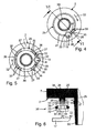
- the positioning device 25 comprises at least one filter element-side positioning element, which is formed here by a sliding surface 26 at the free end of the pin 22, and at least one filter housing-side positioning, which is formed here by a ramp 27.
- the positioning elements 26, 27 are designed so that they cooperate when inserting the filter element 3 in the filter housing 2 for finding a aligned in a direction of insertion 28 of the pin 22 alignment between the pin 22 and the return opening 19.
- said ramp 27 is provided as the filter housing-side positioning element, which ramp projects axially into the raw space 13.
- the ramp 27 begins at 29 at the return opening 19 and ends at 30 also at the return opening 19. Between its beginning 29 and its end 30, the ramp 27 extends concentrically to the longitudinal center axis 16 of the filter housing 2 circular or helical. From its beginning 29 to its end 30, the ramp 27 drops towards the return opening 19.
- said sliding surface 26 is formed on the pin 22 and that at a side remote from the end plate 17 side of the pin 22.
- the pin 22 is in this case arranged eccentrically with respect to the longitudinal central axis 15 of the filter element 3, wherein the eccentricity of the pin 22 is about the same size is like the radius of the ramp 27.
- the pin 22 during insertion of the filter element 3 coaxial with the longitudinal center axis 16 of the filter housing 2 with its sliding surface 26 axially on the ramp 27 come into contact.
- the pin 22 slides with its sliding surface 26 along the ramp 27 from. This inevitably takes place the orientation of the pin 22 to the return opening 19.
- a corresponding sliding movement is in Fig. 2 symbolized by an arrow 32.
- the orientation of the ramp slope is expediently chosen so that the direction of rotation when tightening the bottom 8 for the filter element 3 arranged therein inevitably generates the desired rotational movement 31, whereby the filter element 3 automatically slides along the ramp 27 when attaching the bottom 8.
- the filter element 3 Upon reaching the aligned alignment between pin 22 and return opening 19 of the beginning 29 of the ramp 27 limits further rotation of the filter element 3. Upon further tightening the bottom 8, the filter element 3 is necessarily inserted with its pin 22 corresponding to the insertion direction 28 in the return opening 19.
- the fuel filter 1 may also be equipped with a guide device 33.
- This guide device 33 may have at least one filter element-side guide element, which may be formed, for example, by a guide section 34 formed on the pin 22, and at least one guide housing element on the filter housing, which may be formed, for example, by one or more guide walls 35.
- the guide elements 34, 35 are designed so that they interact when inserting the filter element 3 in the filter housing 2 according to the "key lock principle". This means that the guide elements 34, 35 allow the interaction between the positioning elements 26, 27, ie between the ramp 27 and the sliding surface 26 only when the mating guide element 34, 35 cooperate with each other. If the guide elements 34, 35 cooperate with one another when inserting the filter element 3 into the filter housing 2, the cooperation of the positioning elements 26, 27 for locating the aligned alignment between the pin 22 and the return opening 19 is considerably hindered by the guide device 33 or impossible.
- the filter housing-side guide elements are formed by guide walls 35 which extend radially inward and / or radially outward along at least one extension section 36 of the ramp 27 and protrude beyond the ramp 27 in the axial direction.
- a single extension portion 36 is provided, which is positioned in the region of the end 30 of the ramp 27.
- two parallel guide walls 35 are provided in the extension section 36, one of which limits the ramp 27 radially inward and the other radially outward.
- a total of three extension portions 36 are provided, in each of which two parallel guide walls 35 are provided, which limit the ramp 27 radially inwardly and outwardly.
- the filter element-side guide element is formed in the embodiments shown here by the guide portion 34 which projects axially on the side facing away from the end plate 17 or the side of the pin 22.
- Said guide portion 34 has the sliding surface 26 of the pin 22.
- the guide portion 34 is matched with respect to its positioning on the pin 22 and with respect to its dimensioning on the guide walls 35 that extends the guide portion 34 during assembly of the fuel filter 1 radially adjacent to the respective guide wall 35 and between the two parallel guide walls 35 and the sliding surface 26 axially abuts the ramp 27 and holds the pin 22 axially spaced from the respective guide wall 35. This connection is particularly clear in Fig. 6 recognizable.
- the guide portion 34 contacts with the sliding surface 26 extending between the guide walls 35 ramp 27 and ensures an axial clearance between the walls 35 and remote from the end plate 17 outside 37 of the pin 22, from which the guide portion 34 protrudes.
- Said outer surface 37 may be flat and may pass over a phase 38 in the remaining pin 22.
- the above key-lock principle now causes the pin 22 with its sliding surface 26 can slide along the entire ramp 27 to the alignment alignment with the return opening 19 only when the guide portion 34 is present when the guide portion 34 in the radial direction is sufficiently narrow to fit between the opposing guide walls 35, and when the guide portion 35 in the axial direction is sufficiently long to adjust the required axial clearance between pin 22 and the guide walls 35. If the guide section 34 is missing or incorrect, the pin 22 would come into abutment against the end walls of the walls 35 when sliding along the ramp 27 in the circumferential direction, whereby the rotatability of the filter element 3 is blocked. The filter element 3 can then not be mounted properly without further ado.
- FIG. 3 to 6 an outlet port 39 is shown, which may be provided on the cover 7 and on which the filter element 3 can be plugged.
- Fig. 6 shows one special embodiment in which the pin 22 is attached via a web 40 on the end plate 17. Said web 40 is flexible in the radial direction and allows a tolerance compensation between the radial position of the guide portion 34 and the radial position of the guide walls 35. As out Fig. 1 it can be seen, the pin 22 may also be mounted comparatively stiff on the end plate 17.
Landscapes
- Engineering & Computer Science (AREA)
- Chemical & Material Sciences (AREA)
- Combustion & Propulsion (AREA)
- Mechanical Engineering (AREA)
- General Engineering & Computer Science (AREA)
- Chemical Kinetics & Catalysis (AREA)
- Filtration Of Liquid (AREA)
- Fuel-Injection Apparatus (AREA)
Priority Applications (1)
| Application Number | Priority Date | Filing Date | Title |
|---|---|---|---|
| PL07729857T PL2029885T3 (pl) | 2006-06-16 | 2007-06-04 | Filtr paliwa |
Applications Claiming Priority (2)
| Application Number | Priority Date | Filing Date | Title |
|---|---|---|---|
| DE102006028148A DE102006028148A1 (de) | 2006-06-16 | 2006-06-16 | Kraftstofffilter |
| PCT/EP2007/055469 WO2007144288A1 (de) | 2006-06-16 | 2007-06-04 | Kraftstofffilter |
Publications (2)
| Publication Number | Publication Date |
|---|---|
| EP2029885A1 EP2029885A1 (de) | 2009-03-04 |
| EP2029885B1 true EP2029885B1 (de) | 2014-03-05 |
Family
ID=38521108
Family Applications (1)
| Application Number | Title | Priority Date | Filing Date |
|---|---|---|---|
| EP07729857.8A Active EP2029885B1 (de) | 2006-06-16 | 2007-06-04 | Kraftstofffilter |
Country Status (7)
| Country | Link |
|---|---|
| US (4) | US20090230048A1 (enExample) |
| EP (1) | EP2029885B1 (enExample) |
| JP (1) | JP5101609B2 (enExample) |
| CN (1) | CN101466942B (enExample) |
| DE (1) | DE102006028148A1 (enExample) |
| PL (1) | PL2029885T3 (enExample) |
| WO (1) | WO2007144288A1 (enExample) |
Cited By (2)
| Publication number | Priority date | Publication date | Assignee | Title |
|---|---|---|---|---|
| DE102018219351A1 (de) | 2018-11-13 | 2020-05-14 | Mahle International Gmbh | Kraftstoffsystem |
| WO2021144032A1 (en) | 2020-01-17 | 2021-07-22 | Volvo Truck Corporation | Liquid filter equipped with an anti-leakage valve |
Families Citing this family (21)
| Publication number | Priority date | Publication date | Assignee | Title |
|---|---|---|---|---|
| DE102007062100A1 (de) * | 2007-12-21 | 2009-06-25 | Mahle International Gmbh | Flüssigkeitsfilter, insbesondere Ölfilter |
| DE102007062102A1 (de) * | 2007-12-21 | 2009-06-25 | Mahle International Gmbh | Filtereinrichtung |
| US20090283068A1 (en) * | 2008-05-15 | 2009-11-19 | William L Willison | Fuel filter assembly with pressure sending unit |
| DE202008014512U1 (de) * | 2008-10-31 | 2010-03-25 | Mann+Hummel Gmbh | Filtersystem zur Filtration eines Fluides |
| DE102009049868A1 (de) | 2009-10-20 | 2011-04-21 | Mahle International Gmbh | Filtereinrichtung |
| DE102010011290A1 (de) * | 2010-03-13 | 2011-09-15 | Mahle International Gmbh | Filtereinrichtung |
| DE102010043836A1 (de) | 2010-11-04 | 2012-05-10 | Hengst Gmbh & Co. Kg | Filter mit einem austauschbaren Filtereinsatz |
| DE102010062813A1 (de) * | 2010-12-10 | 2012-06-14 | Mahle International Gmbh | Kraftstofffilter |
| DE202011104686U1 (de) | 2011-08-18 | 2011-12-19 | Mahle International Gmbh | Flüssigkeitsfilter, insbesondere ein Ölfilter |
| US11975279B2 (en) | 2012-01-12 | 2024-05-07 | Davco Technology, Llc | Fluid filter assembly with a filter cartridge and housing interface |
| DE102012213163A1 (de) * | 2012-07-26 | 2014-01-30 | Mahle International Gmbh | Filtereinrichtung |
| WO2014165606A2 (en) * | 2013-04-03 | 2014-10-09 | Donaldson Company, Inc. | Liquid filter assembly and methods |
| BR102013011661A8 (pt) * | 2013-05-10 | 2021-04-13 | Mahle Int Gmbh | filtros e base de um elemento filtrante |
| PL3208455T3 (pl) * | 2016-02-16 | 2018-09-28 | Willibrord Lösing Filterproduktion Gmbh | Urządzenie do oczyszczania ciekłego medium |
| DE102016209919A1 (de) * | 2016-06-06 | 2017-12-07 | Mahle International Gmbh | Filtereinrichtung |
| US11426687B2 (en) | 2019-06-27 | 2022-08-30 | Mahle International Gmbh | Fuel filter |
| US11452956B2 (en) | 2019-06-27 | 2022-09-27 | Mahle International Gmbh | Fuel filter |
| US11992788B2 (en) | 2019-06-27 | 2024-05-28 | Mahle International Gmbh | Filter device |
| US11511217B2 (en) | 2020-09-22 | 2022-11-29 | Mahle International Gmbh | Filter and method of fabricating same |
| USD958288S1 (en) | 2020-10-09 | 2022-07-19 | Mahle International Gmbh | Filter device |
| CN113982800B (zh) * | 2021-10-25 | 2022-10-04 | 安庆中船柴油机有限公司 | 一种船用柴油机燃油过滤器及过滤方法 |
Family Cites Families (20)
| Publication number | Priority date | Publication date | Assignee | Title |
|---|---|---|---|---|
| US3295507A (en) * | 1964-07-06 | 1967-01-03 | Aaron D Carter | Lubrication system for internal combustion engines |
| US4617116A (en) * | 1984-05-04 | 1986-10-14 | Ford Motor Company | Automotive type fuel feed system |
| GB2158150B (en) * | 1984-05-04 | 1987-07-15 | Ford Motor Co | I c engine fuel injection supply system |
| DE3422979A1 (de) * | 1984-06-22 | 1986-01-02 | Robert Bosch Gmbh, 7000 Stuttgart | Filter fuer dieselkraftstoff |
| US5547572A (en) * | 1985-05-14 | 1996-08-20 | Parker Hannifin Corporation | Fuel Filter |
| US4997555A (en) * | 1985-05-14 | 1991-03-05 | Parker Hannifin Corporation | Fuel filter assembly with heater |
| FR2618490A1 (fr) * | 1987-07-22 | 1989-01-27 | Rivapompe Sa | Dispositif de filtrage et de degazage d'un carburant d'alimentation pour moteur a combustion interne |
| DE4344588A1 (de) * | 1993-12-24 | 1995-06-29 | Knecht Filterwerke Gmbh | Kraftstoffilter |
| JPH08158975A (ja) * | 1994-12-09 | 1996-06-18 | Mitsubishi Motors Corp | 燃料供給装置 |
| US5649561A (en) * | 1996-05-03 | 1997-07-22 | Parr Manufacturing, Inc. | Fuel filter and pressure regulator system |
| IT1290008B1 (it) * | 1997-03-03 | 1998-10-19 | Bitron Spa | Sistema per l'alimentazione di carburante ad un motore, in particolare per autoveicoli |
| US6159383A (en) * | 1998-04-17 | 2000-12-12 | Caterpillar Inc. | Filter head assembly |
| DE19934378A1 (de) * | 1999-07-22 | 2001-01-25 | Mann & Hummel Filter | Filter mit Flüssigkeiten |
| DE19934478B4 (de) | 1999-07-27 | 2007-12-27 | GEMAC-Gesellschaft für Mikroelektronikanwendung Chemnitz mbH | Digitale Interpolationseinrichtung |
| DE19951085A1 (de) * | 1999-10-23 | 2001-04-26 | Mahle Filtersysteme Gmbh | Flüssigkeitsfilter, insbesondere Ölfilter |
| JP4644409B2 (ja) * | 1999-12-03 | 2011-03-02 | パーカー−ハニフイン・コーポレーシヨン | 燃料フィルター用キーラッチ弁 |
| US6481580B1 (en) * | 2000-08-23 | 2002-11-19 | Caterpillar Inc | Fluid filter with locking mechanism |
| CN1399067A (zh) * | 2001-07-21 | 2003-02-26 | 曼内斯曼Vdo股份公司 | 发动机燃料的输送装置 |
| US6899086B2 (en) * | 2002-09-10 | 2005-05-31 | Barry S. Grant | Fuel pressure accumulator with filter and repositionable fuel delivery ring |
| DE10333398A1 (de) * | 2003-07-16 | 2005-02-03 | Joma-Polytec Kunststofftechnik Gmbh | Ölfilteranordnung |
-
2006
- 2006-06-16 DE DE102006028148A patent/DE102006028148A1/de not_active Withdrawn
-
2007
- 2007-06-04 JP JP2009514751A patent/JP5101609B2/ja active Active
- 2007-06-04 CN CN2007800215764A patent/CN101466942B/zh active Active
- 2007-06-04 EP EP07729857.8A patent/EP2029885B1/de active Active
- 2007-06-04 US US12/304,831 patent/US20090230048A1/en not_active Abandoned
- 2007-06-04 WO PCT/EP2007/055469 patent/WO2007144288A1/de not_active Ceased
- 2007-06-04 PL PL07729857T patent/PL2029885T3/pl unknown
-
2016
- 2016-09-02 US US15/256,035 patent/US10371108B2/en active Active
-
2019
- 2019-07-07 US US16/504,326 patent/US11300082B2/en active Active
-
2022
- 2022-03-08 US US17/689,502 patent/US12241439B2/en active Active
Cited By (3)
| Publication number | Priority date | Publication date | Assignee | Title |
|---|---|---|---|---|
| DE102018219351A1 (de) | 2018-11-13 | 2020-05-14 | Mahle International Gmbh | Kraftstoffsystem |
| WO2020099423A1 (de) | 2018-11-13 | 2020-05-22 | Mahle International Gmbh | Kraftstoffsystem |
| WO2021144032A1 (en) | 2020-01-17 | 2021-07-22 | Volvo Truck Corporation | Liquid filter equipped with an anti-leakage valve |
Also Published As
| Publication number | Publication date |
|---|---|
| US20170009716A1 (en) | 2017-01-12 |
| US11300082B2 (en) | 2022-04-12 |
| CN101466942B (zh) | 2012-01-25 |
| US12241439B2 (en) | 2025-03-04 |
| EP2029885A1 (de) | 2009-03-04 |
| CN101466942A (zh) | 2009-06-24 |
| DE102006028148A1 (de) | 2007-12-20 |
| JP2009540209A (ja) | 2009-11-19 |
| WO2007144288A1 (de) | 2007-12-21 |
| US20190331072A1 (en) | 2019-10-31 |
| US20090230048A1 (en) | 2009-09-17 |
| US10371108B2 (en) | 2019-08-06 |
| US20220186694A1 (en) | 2022-06-16 |
| PL2029885T3 (pl) | 2014-07-31 |
| JP5101609B2 (ja) | 2012-12-19 |
Similar Documents
| Publication | Publication Date | Title |
|---|---|---|
| EP2029885B1 (de) | Kraftstofffilter | |
| EP2222384B1 (de) | Filtereinrichtung und filterelement | |
| EP0707542B1 (de) | Einrichtung zum fördern von kraftstoff aus einem vorratstank zu einer brennkraftmaschine | |
| EP1974786B1 (de) | Flüssigkeitsfilter | |
| EP2519333B1 (de) | Filtervorrichtung sowie filterelement zur benutzung bei einer solchen filtervorrichtung | |
| EP1222010B1 (de) | Flüssigkeitsfilter, insbesondere ölfilter | |
| EP2649292A1 (de) | Kraftstofffilter | |
| DE102007062221A1 (de) | Flüssigkeitsfilter | |
| EP2605849A1 (de) | Filter zur filtrierung von fluiden, filtertopf und filterkopf | |
| EP1937962B1 (de) | Verbrennungsmotor, insbesondere eines kraftfahrzeugs, mit einer kraftstofffiltereinrichtung | |
| EP2227305A2 (de) | Flüssigkeitsfilter, insbesondere ölfilter | |
| EP2337618B1 (de) | Filtereinrichtung | |
| EP2482950A1 (de) | Druckfiltereinrichtung | |
| EP3458175B1 (de) | Filtereinrichtung | |
| EP2263773B1 (de) | Filtereinrichtung | |
| EP2234690B1 (de) | Filteranlage | |
| EP2263772B1 (de) | Filtereinrichtung | |
| DE102009050158A1 (de) | Filtereinrichtung | |
| DE102009001564B4 (de) | Drosselelement | |
| DE102013008987A1 (de) | Filterelement | |
| EP3567242B1 (de) | Kraftstofffördervorrichtung | |
| EP2953702B1 (de) | Flüssigkeitsfilter | |
| DE102015222425A1 (de) | Spin-On Wechselfilter | |
| EP3099394A1 (de) | Filtereinrichtung mit leerlauf im deckel | |
| EP3666357A1 (de) | Filtereinrichtung |
Legal Events
| Date | Code | Title | Description |
|---|---|---|---|
| PUAI | Public reference made under article 153(3) epc to a published international application that has entered the european phase |
Free format text: ORIGINAL CODE: 0009012 |
|
| 17P | Request for examination filed |
Effective date: 20081112 |
|
| AK | Designated contracting states |
Kind code of ref document: A1 Designated state(s): AT BE BG CH CY CZ DE DK EE ES FI FR GB GR HU IE IS IT LI LT LU LV MC MT NL PL PT RO SE SI SK TR |
|
| AX | Request for extension of the european patent |
Extension state: AL BA HR MK RS |
|
| DAX | Request for extension of the european patent (deleted) | ||
| RBV | Designated contracting states (corrected) |
Designated state(s): DE FR GB PL TR |
|
| GRAP | Despatch of communication of intention to grant a patent |
Free format text: ORIGINAL CODE: EPIDOSNIGR1 |
|
| INTG | Intention to grant announced |
Effective date: 20131028 |
|
| GRAS | Grant fee paid |
Free format text: ORIGINAL CODE: EPIDOSNIGR3 |
|
| GRAA | (expected) grant |
Free format text: ORIGINAL CODE: 0009210 |
|
| AK | Designated contracting states |
Kind code of ref document: B1 Designated state(s): DE FR GB PL TR |
|
| REG | Reference to a national code |
Ref country code: GB Ref legal event code: FG4D Free format text: NOT ENGLISH |
|
| REG | Reference to a national code |
Ref country code: DE Ref legal event code: R096 Ref document number: 502007012823 Country of ref document: DE Effective date: 20140417 |
|
| REG | Reference to a national code |
Ref country code: PL Ref legal event code: T3 |
|
| REG | Reference to a national code |
Ref country code: DE Ref legal event code: R097 Ref document number: 502007012823 Country of ref document: DE |
|
| PLBE | No opposition filed within time limit |
Free format text: ORIGINAL CODE: 0009261 |
|
| STAA | Information on the status of an ep patent application or granted ep patent |
Free format text: STATUS: NO OPPOSITION FILED WITHIN TIME LIMIT |
|
| 26N | No opposition filed |
Effective date: 20141208 |
|
| GBPC | Gb: european patent ceased through non-payment of renewal fee |
Effective date: 20140605 |
|
| REG | Reference to a national code |
Ref country code: DE Ref legal event code: R097 Ref document number: 502007012823 Country of ref document: DE Effective date: 20141208 |
|
| PG25 | Lapsed in a contracting state [announced via postgrant information from national office to epo] |
Ref country code: GB Free format text: LAPSE BECAUSE OF NON-PAYMENT OF DUE FEES Effective date: 20140605 |
|
| REG | Reference to a national code |
Ref country code: FR Ref legal event code: PLFP Year of fee payment: 10 |
|
| REG | Reference to a national code |
Ref country code: FR Ref legal event code: PLFP Year of fee payment: 11 |
|
| REG | Reference to a national code |
Ref country code: FR Ref legal event code: PLFP Year of fee payment: 12 |
|
| PGFP | Annual fee paid to national office [announced via postgrant information from national office to epo] |
Ref country code: FR Payment date: 20220623 Year of fee payment: 16 |
|
| PG25 | Lapsed in a contracting state [announced via postgrant information from national office to epo] |
Ref country code: FR Free format text: LAPSE BECAUSE OF NON-PAYMENT OF DUE FEES Effective date: 20230630 |
|
| P01 | Opt-out of the competence of the unified patent court (upc) registered |
Effective date: 20240527 |
|
| PGFP | Annual fee paid to national office [announced via postgrant information from national office to epo] |
Ref country code: PL Payment date: 20250523 Year of fee payment: 19 Ref country code: DE Payment date: 20250618 Year of fee payment: 19 |
|
| PGFP | Annual fee paid to national office [announced via postgrant information from national office to epo] |
Ref country code: TR Payment date: 20250527 Year of fee payment: 19 |