EP2028498B1 - Systeme und Verfahren für einen Strombegrenzer für offene Stromkreise - Google Patents
Systeme und Verfahren für einen Strombegrenzer für offene Stromkreise Download PDFInfo
- Publication number
- EP2028498B1 EP2028498B1 EP08162395.1A EP08162395A EP2028498B1 EP 2028498 B1 EP2028498 B1 EP 2028498B1 EP 08162395 A EP08162395 A EP 08162395A EP 2028498 B1 EP2028498 B1 EP 2028498B1
- Authority
- EP
- European Patent Office
- Prior art keywords
- current
- resistance
- magnitude
- measuring
- measurement
- Prior art date
- Legal status (The legal status is an assumption and is not a legal conclusion. Google has not performed a legal analysis and makes no representation as to the accuracy of the status listed.)
- Not-in-force
Links
Images


Classifications
-
- G—PHYSICS
- G01—MEASURING; TESTING
- G01R—MEASURING ELECTRIC VARIABLES; MEASURING MAGNETIC VARIABLES
- G01R15/00—Details of measuring arrangements of the types provided for in groups G01R17/00 - G01R29/00, G01R33/00 - G01R33/26 or G01R35/00
- G01R15/12—Circuits for multi-testers, i.e. multimeters, e.g. for measuring voltage, current, or impedance at will
-
- G—PHYSICS
- G01—MEASURING; TESTING
- G01R—MEASURING ELECTRIC VARIABLES; MEASURING MAGNETIC VARIABLES
- G01R27/00—Arrangements for measuring resistance, reactance, impedance, or electric characteristics derived therefrom
- G01R27/02—Measuring real or complex resistance, reactance, impedance, or other two-pole characteristics derived therefrom, e.g. time constant
- G01R27/08—Measuring resistance by measuring both voltage and current
Definitions
- Electrical multimeters can typically perform measurement of a wide range of physical and electrical parameters. Some may have a low-ohms measurement function for measuring small electrical resistances, e.g., less than 100 ohms. To implement the low-ohms measurement function, the multimeter will typically include a current source that can be coupled by a pair of electrical leads to an unknown resistance to be measured.
- a user may frequently leave a multimeter powered on in a low-ohms measurement mode while the multimeter is not taking a live measurement.
- the electrical leads will form an open-circuit.
- a typical multimeter device may continue to draw a substantial amount of current from its battery power source. Such current consumption while at idle may significantly decrease the battery life of a portable multimeter device.
- WO 2006/092767 discloses the incorporation of an impedance detector into an electrical device to produce a zero-power supervision of a condition when to resume operation.
- a current measuring component configured to measure the magnitude of the current generated by the current generating component.
- the current measuring component may comprise a level shifter circuit configured to amplify and output a voltage drop across a resistor located along a current path of the current generated by the current generating component.
- the current control component optionally controls the current generating component by modulating a switch connected along the current path in response to the detected voltage level.
- the apparatus comprises a battery-powered handheld electrical multimeter.
- the present invention provides a method of controlling output current in an electronic apparatus capable of measuring electrical resistance, comprising:
- the method further comprises measuring a voltage drop across the target resistance when the target resistance is connected between the first and second measurement terminals. Also it may further comprise computing the magnitude of the target resistance based on the measured voltage drop and the operating current.
- the method further comprises actuating a switch connected along a current path of the operating current in response to the rise in the voltage level of the first measurement terminal to reduce the operating current to the second magnitude.
- a transistor may be switched from a fully-on state to a partially-on state in response to the rise in the voltage level of the first measurement terminal.
- the present invention also provides an apparatus for measuring resistance, comprising:
- the apparatus further comprises a current measuring component configured to measure the magnitude of the first current.
- the current measuring component may comprise a level shifter circuit configured to amplify and output a voltage drop across a resistor of known resistance located along the current path.
- the current generating component may comprise a voltage source.
- the current control component controls the current generating component by actuating a switch connected along the current path in response to the voltage level of the first measurement terminal.
- FIG. 1 is a schematic diagram illustrating a front face of an example digital multimeter.
- Figure 2 is a conceptual block diagram illustrating various components of an example circuit for measuring electrical resistance.
- Figures 3A and 3B are circuit diagrams illustrating example circuits for measuring electrical resistance.
- Figure 4 is a circuit diagram illustrating an example implementation of a control circuit.
- Figure 5 is a flowchart illustrating an example method for measuring electrical resistance and reducing operating current.
- Circuits and methods for measuring electrical resistance are disclosed below. These circuits and methods are well adapted for implementation within electrical multimeters, but could also be implemented in other devices or systems, including stand-alone resistance measuring systems. The circuits and methods described below could also be adapted to function in other systems or devices in which an open-circuit configuration is maintained for some period of time.
- a multimeter 100 comprises a display 105 and a rotary switch 120.
- a user can interact with the multimeter using any of several interfaces.
- buttons and/or rotary switch 120 can be used to request various measurements and/or processed versions of those measurements.
- a secondary button can be pressed to select any rotary switch alternate function.
- Other buttons can be used to choose modifiers for the selected function.
- Analog connections on input jacks 121-124 can be used to provide measurement inputs to multimeter 100.
- four jacks can be included along the bottom of multimeter 100 where the user can connect input probes for measuring signals of interest.
- Output is presented to the user via display 105, which is shown as a liquid crystal (LCD) display in Figure 1 .
- the LCD display could be substituted by an indicator light, and/or an audible beeper.
- a remote interface could be used to control and query multimeter 100.
- An area between display 105 and rotary switch 120 contains various soft keys and buttons.
- a lower portion of display 105 contains labels 106 corresponding to soft keys 107 (labeled [F1] through [F4]) below display 105. Pressing one of the soft keys invokes a function indicated by the corresponding label on the display.
- Multimeter 100 further comprises navigation buttons 114, an on/off switch 118, and a backlight control button 119.
- the meter can use AA alkaline or rechargeable batteries and can use any of several techniques to conserve battery power.
- rotary switch 120 is rotated to a position 150 labeled "LoZ.”
- multimeter 100 operates in the low-ohms measurement mode and can employ various techniques to measure unknown resistances connected between electrical leads corresponding to a pair of input jacks 121-124.
- the low-ohms measurement function of a multimeter or other device can be implemented by a resistance measurement circuit comprising an active portion and a pair of measurement terminals corresponding to a pair of electrical leads or another type of connection component.
- Figure 2 shows a block diagram conceptually illustrating various components of a resistance measurement circuit in accordance with selected embodiments of the invention.
- a resistance measurement circuit 200 comprises an active portion 201 and respective first and second measurement terminals 206 and 207.
- Resistance measurement circuit 200 has relatively large internal resistances Ri1 and Ri2, with resistance Ri2 being connected between the first and second measurement terminals.
- an unknown resistance Rx is connected between first and second measurement terminals 206 and 207 so that its resistance can be measured.
- a resistance to be measured can be referred to as a "target resistance”.
- such resistances may also be referred to as "unknown resistances”.
- the target resistance or unknown resistance described herein can be any form of or type of electrical component, part or device which has a resistivity. Where a connection is made between first and second measurement terminals 206 and 207, resistance measurement circuit 200 will be considered to be in a closed-circuit configuration. Where no connection is made between first and second measurement terminals 206 and 207, resistance measurement circuit 200 will be considered to be in an open-circuit configuration.
- active portion 201 When resistance measurement circuit 200 is in the closed-circuit configuration, active portion 201 is controlled to generate a first current having a first magnitude through a circuit node labeled n1. Because unknown resistance Rx is relatively small compared with internal resistance Ri2, most of the current passing through node n1 flows through unknown resistance Rx. On the other hand, where resistance measurement circuit 200 is in the open-circuit configuration, active portion 201 is controlled to generate a second current having a second magnitude through node n1. In order to limit power consumption, active portion 201 controls the magnitude of the second current such that it is smaller than the magnitude of the first current used in the closed circuit configuration.
- resistance measurement circuit 200 is designed so that the magnitude of the first current is sufficiently large to achieve strong signals for measuring the magnitude of unknown resistance Rx. For instance, a relatively large current may be required to achieve a voltage drop across resistance Rx that can be readily detected.
- Active portion 201 comprises a current generating component 202, a current control component 203, a voltage measuring component 204, and a current measuring component 205.
- current generating component 202 generates a current for measuring the resistance of unknown resistance Rx.
- the concept of current generation as used in this description should be viewed in a broad sense as encompassing a variety of current generation techniques and should not be construed as limited to specific types of current sources generating a static output current.
- a current generating component generating a particular current may be embodied by a collection of multiple discrete components within a circuit. For example, a voltage source coupled to a set of resistances may generate a certain current when coupled to a particular target resistance.
- current generating component 202 can be designed to generate a known stable current through unknown resistance Rx when resistance measuring circuit 200 is in the closed-circuit configuration.
- active portion 201 may include components capable of changing the magnitude of current flowing through unknown resistance Rx.
- other components can be used to measure the magnitude of the current flowing through unknown resistance Rx to generate a resistance measurement.
- active portion 201 may include variable resistance components such as thermistors in the current path passing through node n1.
- it will be assumed that the current flowing through unknown resistances will be measured to obtain resistance measurements.
- resistance measurements can be obtained by using a current whose magnitude in the closed-circuit configuration is known a priori.
- Current control component 203 operates to control the flow of current through node n1 in the respective closed and open circuit configurations. During the closed-circuit configuration, current control component 203 allows the first current having the relatively large first magnitude to flow through node n1, and during the open-circuit configuration, current control component 203 limits the flow of current through node n1 to the second magnitude, which is smaller than the first magnitude.
- the current control component 203 functions by limiting the flow of current in response to an elevated voltage level of node n1 or measurement terminal 206. For instance, when unknown resistance Rx is disconnected from first and second measurement terminals 206 and 207, the voltage level of node n1 rises. In response to this rise, current control component 203 attenuates the current through node n1 by, e.g., partially closing a switch along the current path through node n1.
- Vx and Ix can be measured using any of several conventional techniques, including but not limited to, e.g., measuring voltages and currents of components other than unknown resistance Rx and then inferring or approximating Vx and/or Ix from these measurements.
- the values of Vx and Ix can be digitally sampled and/or processed to compute the magnitude of unknown resistance Rx.
- sampling and/or processing can be accomplished, e.g., using components such as conventional analog-to-digital (A-D) conversion units or other more specialized sampling and/or processing components.
- A-D analog-to-digital
- such sampling and/or processing components could be included in active portion 201 or connected to active portion 201 via input/output interfaces.
- FIGS 3A and 3B are schematic diagrams illustrating a resistance measurement circuit 300 implementing a low-ohms measurement function.
- Resistance measurement circuit 300 can be used to implement resistance measurement circuit 200. Like other resistance measurement circuits discussed herein, resistance measurement circuit 300 could be implemented in a variety of devices or systems including multimeters. However, it should be noted that some of the components within resistance measurement circuit 300 are especially beneficial in the context of multimeters and therefore may be omitted in other embodiments.
- resistance measurement circuit 300 includes a thermistor adapted to protect its internal circuits against high input currents which may occur in cases such as where measurement terminals of a multimeter are accidentally connected across a high voltage when the multimeter is in a low-ohms measurement mode.
- Figure 3A shows resistance measurement circuit 300 in an open-circuit configuration and Figure 3B shows resistance measurement circuit 300 in a closed-circuit configuration.
- the composition of resistance measurement circuit 300 will be described below with reference to Figure 3A and then selected functions of resistance measurement circuit 300 will be described with reference to Figures 3A and 3B .
- resistance measurement circuit 300 comprises a control circuit 301, a level-shifter 302, first through fourth resistors R1 through R4, a thermistor RT1, a field-effect transistor (FET) Q1, and respective upper and lower measurement terminals HI and COM.
- Level-shifter 302 comprises an operational amplifier (op-amp) U1 and a current mirror, which collectively amplify and output a voltage difference across second resistor R2 to generate a level-shifted output voltage.
- Second resistor R2 has a first terminal connected to a power-supply voltage (e.g., ⁇ 15-24 V) and further connected to a non-positive input of op-amp U1. Second resistor R2 has a second terminal connected to an inverting input of op-amp U1 and further connected to a first terminal (e.g., a source or drain) of FET Q1.
- a power-supply voltage e.g., ⁇ 15-24 V
- Second resistor R2 has a second terminal connected to an inverting input of op-amp U1 and further connected to a first terminal (e.g., a source or drain) of FET Q1.
- Third resistor R3 has a first terminal connected to the output of level shifter 302 and a second terminal connected to a common voltage (e.g., ground or a low power supply voltage).
- the first terminal of third resistor R3 is connected to an analog-to-digital (A-D) converter as indicated by an arrow labeled "VR".
- the A-D converter is used to sample and digitize the voltage level of the first terminal of third resistor R3 when the low-ohms measurement function is being performed.
- FET Q1 has its first terminal connected to the second terminal of second resistor R2, a second terminal (e.g., a source or drain) connected to a first terminal of thermistor RT1, and a third terminal (e.g., a gate) connected to control circuit 301.
- a second terminal e.g., a source or drain
- a third terminal e.g., a gate
- Thermistor RT1 has its first terminal connected to the second terminal of FET Q1 and a second terminal connected to a first terminal of first resistor R1.
- First resistor R1 has its first terminal connected to the second terminal of thermistor RT1 and a second terminal connected to upper measurement terminal HI.
- Fourth resistor R4 has a first terminal connected to upper measurement terminal HI and a second terminal connected to control circuit 301.
- Control circuit 301 is connected to the third terminal of FET Q1, the second terminal of fourth resistor R4, and lower measurement terminal COM, which is connected to the common voltage. Control circuit 301 is also connected to an application specific integrated circuit (ASIC) as indicated by an arrow labeled "VM".
- ASIC application specific integrated circuit
- the ASIC may function, for example, to receive and manipulate various measurement values performed by resistance measurement circuit 300. In addition, the ASIC may coordinate different functions of a multimeter including resistance measurement circuit 300.
- control circuit 301 operates in response to changes in the voltage level of upper measurement terminal HI to control the gate bias of FET Q1 and thereby modify the magnitude of current flowing through a current path including thermistor RT1 and first transistor R1.
- control circuit 301 operates to control the gate bias voltage of FET Q1 such that a relatively smaller current flows through this current path during the open-circuit configuration, and such that a relatively larger current flows through this current path during the closed-circuit configuration.
- resistance measurement circuit 300 To further illustrate the operation of resistance measurement circuit 300, an example of resistance measurement circuit 300 is described using specific values of voltages, currents, and resistances. This example is provided for illustrative purposes, and not by way of limitation.
- the power source voltage has a magnitude of 20V
- the common voltage has a magnitude of 0V
- first resistor R1 has a resistance of 1k ohm
- second resistor R2 has a resistance of 10 ohms
- third resistor R3 has a resistance of about 5k ohms
- fourth resistor R4 has a resistance of about 1M ohm
- thermistor RT1 has a resistance of 1k ohm
- unknown resistance Rx has a magnitude less than 100 ohms.
- resistance measurement circuit 300 is in the closed-circuit configuration illustrated in Figure 3B , nearly 10 milliamperes (mA) of current flows through a current path including first thermistor TR1 and first resistor R1.
- mA milliamperes
- level-shifter 302 amplifies a voltage drop across second resistor R2 to generate a level-shifted output voltage on the first terminal of third resistor R3.
- the level-shifted output voltage of third resistor R3 is then sampled by the A-D converter indicated by the reference label "VR" to generate a measured value of the current passing through second transistor R2.
- the measured current passing through second resistor R2 is generated by evaluating the amplified voltage drop across second resistor R2 in view of the resistance of second and third resistors R2 and R3 and electrical characteristics of level-shifter 302.
- the current flowing through second resistor R2 could be computed by applying Ohm's law to the voltage level apparent on the first terminal of third transistor R3 and the resistance value of second resistor R2, and then scaling the result by a gain factor of level-shifter 302.
- fourth resistor R4 is significantly larger than unknown resistance Rx, relatively less current flows across fourth resistor R4 during the closed-circuit configuration of resistance measurement circuit 300. As a result, the measured current flowing across second resistor R2 can be used as an indication, a surrogate, or an approximation of the current flowing across unknown resistance Rx.
- the voltage drop across unknown resistance Rx is calculated by measuring the voltage level of upper measurement terminal HI relative to the level of the common voltage. This measurement can be accomplished by any of a variety of techniques. For example in one embodiment, the measurement is accomplished using a voltage measurement taken across fourth resistor R4.
- measurements have been acquired for the voltage drop across unknown resistance Rx and the current flowing through unknown resistance Rx, these measurements can be combined, typically using Ohm's law, to generate a value for the magnitude of unknown resistance Rx.
- the combination of the measurements can be performed, for example, by a digital logic circuit residing in the ASIC or some other companion circuit of resistance measuring circuit 300.
- resistance measuring circuit 300 is in the closed-circuit configuration illustrated in Figure 3B , using the example components described above, slightly less than 10mA of current flows through unknown resistance Rx and a reduced amount of current flows through fourth resistor R4.
- resistance Rx has a magnitude of less than 100 ohms and lower measurement terminal COM is connected to ground (assumed 0V), then upper measurement terminal HI will have a voltage level of less than 1V during the closed circuit configuration.
- control circuit 301 controls the voltage level of the gate of FET Q1 such that FET Q1 is partially turned off. As a result, the current flowing through the current path including thermistor RT1 and first resistor R1 significantly decreases.
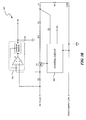
- control circuit 301 An example embodiment implementing control circuit 301 is illustrated in Figure 4 .
- control circuit 301 and resistance measuring circuit 300 both reside within a multimeter.
- different conduction paths are used for the different functions of the multimeter.
- a path at the bottom of Figure 4 labeled "LZ R CO LO" is used for the low-ohms measurement function.
- some features of resistance measurement circuit 300 that are also shown in Figures 3A and 3B are indicated by large-type reference labels for ready comparison.
- control circuit 301 is implemented using an op-amp labeled U2 and related components illustrated in Figure 4 .
- the voltage level of upper measurement terminal HI shown on the left side of Figure 4
- the voltage levels of respective inputs and outputs of op-amp U2 vary such that the current through fourth resistor R4 is reduced during the open-circuit configuration.
- control circuit 301 a variety of different embodiments implementing control circuit 301 based on the description herein can be implemented. For example, different systems and method for controlling the gate voltage of FET Q1 in relation to the voltage level of upper measurement terminal HI can be used.
- FIG 5 is a flowchart broadly illustrating a method of operating a circuit or apparatus capable of measuring electrical resistance in accordance with selected embodiments of the invention.
- method steps will be denoted by parentheses (xxx).
- parentheses xxx
- the method will be described in the context of resistance measuring circuit 300 illustrated in Figure 3 .
- the method could be performed in a variety of different apparatuses employing a pair of measurement terminals to measure an unknown electrical resistance.
- an operating current is generated through an unknown resistance connected between first and second measurement terminals such as upper and lower measurement terminals HI and COM shown in Figure 3 (501).
- first and second measurement terminals such as upper and lower measurement terminals HI and COM shown in Figure 3 (501).
- first and second measurement terminals such as upper and lower measurement terminals HI and COM shown in Figure 3 (501).
- the voltage level of the first measurement terminal is elevated, e.g., in the manner of upper measurement terminal HI in Figure 3 , and this elevation is sensed by a current control component such as control circuit 301 (502).
- the current control component controls a current generating component to reduce the operating current (503). This reduction may be accomplished, for example, in the same manner that control circuit 301 reduces the current flowing through first resistor R1 by placing FET Q1 in the state "partially ON".
- the method illustrated and Figure 5 can be modified in any of several ways and can be embodied in a variety of diverse contexts without departing from the scope of the invention.
- FET field-effect transistor
- many other components having a switch-like functionality could be used to modulate or control the amount of current provided by the power source to the target resistance.
Claims (15)
- Elektrische Vorrichtung, die dazu in der Lage ist, den elektrischen Widerstand (100) eines Zielwiderstands (Rx) zu messen, wobei die Vorrichtung Folgendes umfasst:erste und zweite Messklemmen (206, 207), die so konfiguriert sind, dass sie mit gegenüberliegenden Seiten des Zielwiderstands (Rx) gekoppelt werden;einen Widerstandsmesskreis (300), der mit der ersten und zweiten Messklemme (206, 207) gekoppelt ist;eine Stromerzeugungskomponente (202), die so konfiguriert ist, dass sie einen ersten Strom entlang eines Strompfads zur ersten Messklemme (206) erzeugt, die auf den mit der ersten Messklemme und der zweiten Messklemme gekoppelten Zielwiderstand (Rx) reagiert;eine Spannungsmesskomponente (204) zum Messen eines Spannungspegels zwischen der ersten und zweiten Messklemme; undeine Stromkontrollkomponente (203), die so konfiguriert ist, dass sie Energie spart, indem sie das Ausmaß des von der Stromerzeugungskomponente (202) erzeugten Stroms von einem ersten Strom auf einen zweiten Strom, der niedriger als der erste Strom ist, als Reaktion auf eine Erhöhung des von der Spannungsmesskomponente (204) gemessenen Spannungspegels reduziert.
- Vorrichtung nach Anspruch 1, weiter umfassend:eine Strommesskomponente (205), die so konfiguriert ist, dass sie das Ausmaß des von der Stromerzeugungskomponente (202) erzeugten Stroms misst.
- Vorrichtung nach Anspruch 2, wobei die Strommesskomponente (205) einen Pegelumsetzkreis (302) umfasst, der so konfiguriert ist, dass er einen Spannungsabfall durch einen Resistor (R2), der sich entlang eines Strompfads des von der Stromerzeugungskomponente (202) erzeugten Stroms befindet, verstärkt und ausgibt.
- Vorrichtung nach Anspruch 1,
wobei die Stromkontrollkomponente (203) die Stromerzeugungskomponente (202) kontrolliert, indem sie einen Schalter (Q1), der entlang des Strompfads angeschlossen ist, als Reaktion auf den von der Spannungsmesskomponente (204) gemessenen Spannungspegel moduliert; oder
wobei die Vorrichtung ein batteriebetriebenes elektrisches Handvielfachmessgerät (100) umfasst. - Verfahren zum Reduzieren von Energie, die von einer elektronischen Messvorrichtung, die dazu in der Lage ist, den elektrischen Widerstand eines Zielwiderstands (Rx) zu messen, gebraucht wird, wobei das Verfahren Folgendes umfasst:Messen eines Spannungspegels zwischen einer ersten Messklemme und einer zweiten Messklemme (206, 207);Erzeugen eines Betriebsstroms mit einem ersten Ausmaß entlang eines Strompfads zur ersten Messklemme (206), wobei das Erzeugen des Betriebsstroms eine Reaktion auf den mit der ersten Messklemme und der zweiten Messklemme (207) gekoppelten Zielwiderstand (Rx) ist; undReduzieren des Ausmaßes des Betriebsstroms entlang des Strompfads vom ersten Ausmaß auf ein zweites Ausmaß, das niedriger als das erste Ausmaß ist, als Reaktion auf das Messen einer Erhöhung des Spannungspegels zwischen der ersten Messklemme (206) und der zweiten Messklemme (207), um den Energieverbrauch der elektronischen Vorrichtung zu reduzieren.
- Verfahren nach Anspruch 5, weiter umfassend:Messen eines Spannungsabfalls durch einen Zielwiderstand (Rx), wenn der Zielwiderstand zwischen der ersten und zweiten Messklemme verbunden ist; und,optional weiter umfassend:Berechnen des Ausmaßes des Zielwiderstands (Rx) basierend auf dem von der Spannungsmesskomponente (204) gemessenen Spannungspegel und dem Betriebsstrom.
- Verfahren nach Anspruch 5 oder 6,
weiter umfassend das Reduzieren des Ausmaßes des Betriebsstroms auf ein Nicht-Null-Ausmaß; und / oder
wobei das erste Ausmaß zwischen 5 und 10 mA beträgt und das zweite Ausmaß weniger als 3 mA beträgt. - Verfahren nach Anspruch 5, 6 oder 7, weiter umfassend das Betätigen eines Schalters (Q1), der entlang des Strompfads des Betriebsstroms angeschlossen ist, als Reaktion auf die Erhöhung des Spannungspegels der ersten Messklemme (206), um das Ausmaß des Betriebsstroms auf das zweite Ausmaß zu reduzieren; und
optional weiter umfassend das Umschalten eines Transistors (Q1) von einem vollständig eingeschalteten Zustand in einen teilweise eingeschalteten Zustand als Reaktion auf die Erhöhung des Spannungspegels der ersten Messklemme. - Vorrichtung nach Anspruch 1
wobei die Stromerzeugungskomponente weiter so konfiguriert ist, dass sie:den ersten Strom entlang des Strompfads zur ersten Messklemme (HI) erzeugt, wenn der Widerstandsmesskreis als geschlossener Kreislauf konfiguriert ist;den zweiten Strom entlang des Strompfads erzeugt, wenn der Widerstandsmesskreis als offener Kreislauf konfiguriert ist,wobei die Spannungsmesskomponente weiter so konfiguriert ist, dass sie einen Spannungsabfall durch den Zielwiderstand misst, wenn der Widerstandsmesskreis als geschlossener Kreislauf konfiguriert ist. - Vorrichtung nach Anspruch 9, weiter umfassend:eine Strommesskomponente, die so konfiguriert ist, dass sie das Ausmaß des von der Stromerzeugungskomponente erzeugten Stroms misst.
- Vorrichtung nach Anspruch 10, wobei die Strommesskomponente einen Pegelumsetzkreis (302) umfasst, der so konfiguriert ist, dass er einen Spannungsabfall durch einen Resistor von bekanntem Widerstand, der sich entlang dem Strompfad befindet, verstärkt und ausgibt.
- Vorrichtung nach Anspruch 9, 10 oder 11, wobei die Stromerzeugungskomponente eine Spannungsquelle umfasst.
- Vorrichtung nach einem der Ansprüche 9 bis 12, wobei die Stromkontrollkomponente die Stromerzeugungskomponente durch Betätigen eines entlang des Strompfads angeschlossenen Schalters als Reaktion auf den Spannungspegel der ersten Messklemme kontrolliert.
- Vorrichtung nach Anspruch 13, wobei der Schalter einen Feldeffekttransistor (FET) umfasst.
- Vorrichtung nach einem der Ansprüche 9 bis 14,
wobei das Ausmaß des ersten Stroms zwischen 5 und 10 mA beträgt und das Ausmaß des zweiten Stroms weniger als 3 mA beträgt; und / oder
wobei die Vorrichtung ein batteriebetriebenes elektrisches Handvielfachmessgerät umfasst.
Applications Claiming Priority (1)
| Application Number | Priority Date | Filing Date | Title |
|---|---|---|---|
| US11/838,870 US7990162B2 (en) | 2007-08-14 | 2007-08-14 | Systems and methods for an open circuit current limiter |
Publications (3)
| Publication Number | Publication Date |
|---|---|
| EP2028498A2 EP2028498A2 (de) | 2009-02-25 |
| EP2028498A3 EP2028498A3 (de) | 2013-05-01 |
| EP2028498B1 true EP2028498B1 (de) | 2015-10-07 |
Family
ID=39940649
Family Applications (1)
| Application Number | Title | Priority Date | Filing Date |
|---|---|---|---|
| EP08162395.1A Not-in-force EP2028498B1 (de) | 2007-08-14 | 2008-08-14 | Systeme und Verfahren für einen Strombegrenzer für offene Stromkreise |
Country Status (4)
| Country | Link |
|---|---|
| US (2) | US7990162B2 (de) |
| EP (1) | EP2028498B1 (de) |
| CN (1) | CN101441235B (de) |
| TW (1) | TWI465733B (de) |
Families Citing this family (14)
| Publication number | Priority date | Publication date | Assignee | Title |
|---|---|---|---|---|
| US7990162B2 (en) * | 2007-08-14 | 2011-08-02 | Fluke Corporation | Systems and methods for an open circuit current limiter |
| TWM383120U (en) * | 2009-10-09 | 2010-06-21 | Brymen Technology Corp | Multimeter with filtered measurement mode |
| WO2011142004A1 (ja) * | 2010-05-12 | 2011-11-17 | トヨタ自動車株式会社 | 車両および車両の制御方法 |
| TWI421515B (zh) * | 2010-11-26 | 2014-01-01 | Chroma Ate Inc | 開路偵測方法與具有開路偵測功能之測試載台 |
| LU91839B1 (en) * | 2011-07-08 | 2013-01-09 | Iee Sarl | Impedance measurement system |
| US9568504B2 (en) | 2013-03-15 | 2017-02-14 | Milwaukee Electric Tool Corporation | Digital multi-meter |
| USD723401S1 (en) | 2013-06-19 | 2015-03-03 | Danaher (Shanghai) Industrial Instrumentation Technologies R&D Co., Ltd. | Digital multimeter |
| CN103558445B (zh) * | 2013-11-13 | 2019-05-21 | 福禄克精密测量有限公司 | 电流检测电路以及测量装置 |
| CN106291156B (zh) * | 2015-06-05 | 2019-05-10 | 陕西飞机工业(集团)有限公司 | 一种电流限制器降压工作时间测试电路 |
| JP6716373B2 (ja) * | 2016-07-12 | 2020-07-01 | 日置電機株式会社 | 測定装置 |
| USD820128S1 (en) * | 2016-10-26 | 2018-06-12 | Klein Tools, Inc. | Voltage tester |
| GB2555527B (en) * | 2016-11-01 | 2019-06-05 | Evonetix Ltd | Current Control |
| USD911858S1 (en) * | 2019-04-25 | 2021-03-02 | Klein Tools, Inc. | Test device |
| US11320462B2 (en) * | 2019-12-12 | 2022-05-03 | Innova Electronics Corporation | Electrical probe |
Family Cites Families (21)
| Publication number | Priority date | Publication date | Assignee | Title |
|---|---|---|---|---|
| US3434050A (en) * | 1966-04-25 | 1969-03-18 | Nasa | High impedance measuring apparatus |
| JPS55106365A (en) * | 1979-02-08 | 1980-08-15 | Yokogawa Hokushin Electric Corp | Megger |
| CA1330828C (en) * | 1987-10-09 | 1994-07-19 | Jiri K. Nor | Battery charger |
| US5146150A (en) * | 1990-08-06 | 1992-09-08 | Motorola, Inc. | Safe battery cell interconnects |
| US5477125A (en) * | 1992-09-11 | 1995-12-19 | Inco Limited | Battery charger |
| US5418450A (en) * | 1993-05-03 | 1995-05-23 | John Fluke Mfg. Co., Inc. | Coupling circuit for a measuring instrument |
| DE4331796A1 (de) * | 1993-09-18 | 1995-03-23 | Metrawatt Gmbh Gossen | Multimeter mit automatischer Meßfunktionseinstellung |
| US5578936A (en) * | 1995-01-23 | 1996-11-26 | Fluke Corporation | Method and apparatus for automatically testing semiconductor diodes |
| JP3597303B2 (ja) * | 1996-04-23 | 2004-12-08 | 株式会社ルネサステクノロジ | A/dコンバータのテスト方法及びテスト装置 |
| US6043640A (en) * | 1997-10-29 | 2000-03-28 | Fluke Corporation | Multimeter with current sensor |
| US6278596B1 (en) * | 1999-06-17 | 2001-08-21 | Tektronix, Inc. | Active ground fault disconnect |
| EP1214770A1 (de) * | 1999-09-10 | 2002-06-19 | Intra International AB | Intelligente leistungssteuerung |
| US6943555B2 (en) * | 2002-05-23 | 2005-09-13 | Lockheed Martin Corporation | Redundant safety circuit for squib testing |
| JP2004070543A (ja) * | 2002-08-05 | 2004-03-04 | Rohm Co Ltd | ポインティング制御回路付き磁気センサ |
| CN2582005Y (zh) * | 2002-09-28 | 2003-10-22 | 致茂电子股份有限公司 | 阻抗测量安全启动装置 |
| US6987400B2 (en) * | 2003-05-20 | 2006-01-17 | Panelvision Technologies | Testing flat panel display plates using high frequency AC signals |
| US7282905B2 (en) * | 2004-12-10 | 2007-10-16 | Texas Instruments Incorporated | System and method for IDDQ measurement in system on a chip (SOC) design |
| US20080195169A1 (en) | 2005-03-02 | 2008-08-14 | Koninklijke Philips Electronics N.V. | Low Power Standby Mode Monitor |
| DE102006017239B4 (de) * | 2006-04-12 | 2011-06-16 | Infineon Technologies Austria Ag | Differentieller Levelshifter mit automatischem Fehlerabgleich |
| US7511584B2 (en) * | 2007-07-18 | 2009-03-31 | Smartech Worldwide Limited | Voltage controlled oscillator capable of operating in a wide frequency range |
| US7990162B2 (en) * | 2007-08-14 | 2011-08-02 | Fluke Corporation | Systems and methods for an open circuit current limiter |
-
2007
- 2007-08-14 US US11/838,870 patent/US7990162B2/en active Active
-
2008
- 2008-08-14 EP EP08162395.1A patent/EP2028498B1/de not_active Not-in-force
- 2008-08-14 CN CN2008102154719A patent/CN101441235B/zh active Active
- 2008-08-14 TW TW97131028A patent/TWI465733B/zh active
-
2011
- 2011-08-01 US US13/195,681 patent/US9116177B2/en active Active
Also Published As
| Publication number | Publication date |
|---|---|
| TWI465733B (zh) | 2014-12-21 |
| EP2028498A3 (de) | 2013-05-01 |
| US20110285414A1 (en) | 2011-11-24 |
| CN101441235A (zh) | 2009-05-27 |
| US7990162B2 (en) | 2011-08-02 |
| CN101441235B (zh) | 2012-09-05 |
| US9116177B2 (en) | 2015-08-25 |
| EP2028498A2 (de) | 2009-02-25 |
| US20090045825A1 (en) | 2009-02-19 |
| TW200923378A (en) | 2009-06-01 |
Similar Documents
| Publication | Publication Date | Title |
|---|---|---|
| EP2028498B1 (de) | Systeme und Verfahren für einen Strombegrenzer für offene Stromkreise | |
| US7943034B2 (en) | Method and apparatus for providing a stable voltage to an analytical system | |
| US7071677B2 (en) | Accurate and efficient sensing method for bi-directional signals | |
| CN111263889B (zh) | 用于运行电池传感器的方法和电池传感器 | |
| US8963530B2 (en) | Multi input circuit | |
| CN104236401B (zh) | 一种火工品测试系统及其测试方法 | |
| CN102032953A (zh) | 一种温度测量装置及其方法 | |
| CN103592348A (zh) | 便携式室内空气质量快速检测仪 | |
| CN204085337U (zh) | 一种火工品测试系统 | |
| WO2008030498A3 (en) | Identification with temperature dependent resistive device | |
| US9859878B2 (en) | Control circuit for use with a sensor, and measurement system including such a control circuit | |
| CN203572794U (zh) | 便携式室内空气质量快速检测仪 | |
| EP3728951B1 (de) | Flammenfühlerschaltung mit variabler vorspannung | |
| ATE354101T1 (de) | Schaltervorrichtung | |
| CN110940905A (zh) | Mosfet内阻检测电路及该电路检测mosfet温度的方法 | |
| SG141209A1 (en) | Abnormal magnetoresistive element detection for a disc drive | |
| JPH11275769A (ja) | 自動電源タ―ンオン回路 | |
| CN212749654U (zh) | 一种带电流监测的恒流源电路 | |
| JP2008209998A (ja) | 電圧発生器 | |
| JP2009229254A (ja) | 電気化学式ガス検知装置 | |
| JP4040908B2 (ja) | インピーダンス測定装置 | |
| CN207832908U (zh) | 一种模拟输入采集电路及检测装置 | |
| KR20150071049A (ko) | 온도 센싱 회로 및 그 동작 방법 | |
| CN216669823U (zh) | 气体检测装置及系统 | |
| KR20110035992A (ko) | 온도 감지 원리를 이용하는 스위치 장치 |
Legal Events
| Date | Code | Title | Description |
|---|---|---|---|
| PUAI | Public reference made under article 153(3) epc to a published international application that has entered the european phase |
Free format text: ORIGINAL CODE: 0009012 |
|
| AK | Designated contracting states |
Kind code of ref document: A2 Designated state(s): AT BE BG CH CY CZ DE DK EE ES FI FR GB GR HR HU IE IS IT LI LT LU LV MC MT NL NO PL PT RO SE SI SK TR |
|
| AX | Request for extension of the european patent |
Extension state: AL BA MK RS |
|
| PUAL | Search report despatched |
Free format text: ORIGINAL CODE: 0009013 |
|
| AK | Designated contracting states |
Kind code of ref document: A3 Designated state(s): AT BE BG CH CY CZ DE DK EE ES FI FR GB GR HR HU IE IS IT LI LT LU LV MC MT NL NO PL PT RO SE SI SK TR |
|
| AX | Request for extension of the european patent |
Extension state: AL BA MK RS |
|
| RIC1 | Information provided on ipc code assigned before grant |
Ipc: G01R 15/12 20060101AFI20130325BHEP Ipc: G01R 27/08 20060101ALI20130325BHEP Ipc: G01R 19/165 20060101ALN20130325BHEP |
|
| 17P | Request for examination filed |
Effective date: 20131101 |
|
| RBV | Designated contracting states (corrected) |
Designated state(s): AT BE BG CH CY CZ DE DK EE ES FI FR GB GR HR HU IE IS IT LI LT LU LV MC MT NL NO PL PT RO SE SI SK TR |
|
| RBV | Designated contracting states (corrected) |
Designated state(s): AT BE BG CH CY CZ DE DK EE ES FI FR GB GR HR HU IE IS IT LI LT LU LV MC MT NL NO PL PT RO SE SI SK TR |
|
| AKX | Designation fees paid |
Designated state(s): AT BE BG CH CY CZ DE DK EE ES FI FR GB GR HR HU IE IS IT LI LT LU LV MC MT NL NO PL PT RO SE SI SK TR |
|
| 17Q | First examination report despatched |
Effective date: 20140128 |
|
| 17Q | First examination report despatched |
Effective date: 20140206 |
|
| GRAP | Despatch of communication of intention to grant a patent |
Free format text: ORIGINAL CODE: EPIDOSNIGR1 |
|
| RIC1 | Information provided on ipc code assigned before grant |
Ipc: G01R 27/08 20060101ALI20150302BHEP Ipc: G01R 15/12 20060101AFI20150302BHEP Ipc: G01R 19/165 20060101ALN20150302BHEP |
|
| INTG | Intention to grant announced |
Effective date: 20150326 |
|
| GRAS | Grant fee paid |
Free format text: ORIGINAL CODE: EPIDOSNIGR3 |
|
| GRAA | (expected) grant |
Free format text: ORIGINAL CODE: 0009210 |
|
| AK | Designated contracting states |
Kind code of ref document: B1 Designated state(s): AT BE BG CH CY CZ DE DK EE ES FI FR GB GR HR HU IE IS IT LI LT LU LV MC MT NL NO PL PT RO SE SI SK TR |
|
| REG | Reference to a national code |
Ref country code: GB Ref legal event code: FG4D |
|
| REG | Reference to a national code |
Ref country code: AT Ref legal event code: REF Ref document number: 754074 Country of ref document: AT Kind code of ref document: T Effective date: 20151015 Ref country code: CH Ref legal event code: EP |
|
| REG | Reference to a national code |
Ref country code: IE Ref legal event code: FG4D |
|
| REG | Reference to a national code |
Ref country code: DE Ref legal event code: R096 Ref document number: 602008040494 Country of ref document: DE |
|
| REG | Reference to a national code |
Ref country code: NL Ref legal event code: MP Effective date: 20151007 |
|
| REG | Reference to a national code |
Ref country code: AT Ref legal event code: MK05 Ref document number: 754074 Country of ref document: AT Kind code of ref document: T Effective date: 20151007 |
|
| REG | Reference to a national code |
Ref country code: LT Ref legal event code: MG4D |
|
| PG25 | Lapsed in a contracting state [announced via postgrant information from national office to epo] |
Ref country code: LT Free format text: LAPSE BECAUSE OF FAILURE TO SUBMIT A TRANSLATION OF THE DESCRIPTION OR TO PAY THE FEE WITHIN THE PRESCRIBED TIME-LIMIT Effective date: 20151007 Ref country code: HR Free format text: LAPSE BECAUSE OF FAILURE TO SUBMIT A TRANSLATION OF THE DESCRIPTION OR TO PAY THE FEE WITHIN THE PRESCRIBED TIME-LIMIT Effective date: 20151007 Ref country code: IS Free format text: LAPSE BECAUSE OF FAILURE TO SUBMIT A TRANSLATION OF THE DESCRIPTION OR TO PAY THE FEE WITHIN THE PRESCRIBED TIME-LIMIT Effective date: 20160207 Ref country code: IT Free format text: LAPSE BECAUSE OF FAILURE TO SUBMIT A TRANSLATION OF THE DESCRIPTION OR TO PAY THE FEE WITHIN THE PRESCRIBED TIME-LIMIT Effective date: 20151007 Ref country code: NO Free format text: LAPSE BECAUSE OF FAILURE TO SUBMIT A TRANSLATION OF THE DESCRIPTION OR TO PAY THE FEE WITHIN THE PRESCRIBED TIME-LIMIT Effective date: 20160107 Ref country code: NL Free format text: LAPSE BECAUSE OF FAILURE TO SUBMIT A TRANSLATION OF THE DESCRIPTION OR TO PAY THE FEE WITHIN THE PRESCRIBED TIME-LIMIT Effective date: 20151007 Ref country code: ES Free format text: LAPSE BECAUSE OF FAILURE TO SUBMIT A TRANSLATION OF THE DESCRIPTION OR TO PAY THE FEE WITHIN THE PRESCRIBED TIME-LIMIT Effective date: 20151007 |
|
| REG | Reference to a national code |
Ref country code: DE Ref legal event code: R082 Ref document number: 602008040494 Country of ref document: DE Representative=s name: HERNANDEZ, YORCK, DIPL.-ING., DE |
|
| PG25 | Lapsed in a contracting state [announced via postgrant information from national office to epo] |
Ref country code: PL Free format text: LAPSE BECAUSE OF FAILURE TO SUBMIT A TRANSLATION OF THE DESCRIPTION OR TO PAY THE FEE WITHIN THE PRESCRIBED TIME-LIMIT Effective date: 20151007 Ref country code: GR Free format text: LAPSE BECAUSE OF FAILURE TO SUBMIT A TRANSLATION OF THE DESCRIPTION OR TO PAY THE FEE WITHIN THE PRESCRIBED TIME-LIMIT Effective date: 20160108 Ref country code: SE Free format text: LAPSE BECAUSE OF FAILURE TO SUBMIT A TRANSLATION OF THE DESCRIPTION OR TO PAY THE FEE WITHIN THE PRESCRIBED TIME-LIMIT Effective date: 20151007 Ref country code: FI Free format text: LAPSE BECAUSE OF FAILURE TO SUBMIT A TRANSLATION OF THE DESCRIPTION OR TO PAY THE FEE WITHIN THE PRESCRIBED TIME-LIMIT Effective date: 20151007 Ref country code: PT Free format text: LAPSE BECAUSE OF FAILURE TO SUBMIT A TRANSLATION OF THE DESCRIPTION OR TO PAY THE FEE WITHIN THE PRESCRIBED TIME-LIMIT Effective date: 20160208 Ref country code: LV Free format text: LAPSE BECAUSE OF FAILURE TO SUBMIT A TRANSLATION OF THE DESCRIPTION OR TO PAY THE FEE WITHIN THE PRESCRIBED TIME-LIMIT Effective date: 20151007 Ref country code: AT Free format text: LAPSE BECAUSE OF FAILURE TO SUBMIT A TRANSLATION OF THE DESCRIPTION OR TO PAY THE FEE WITHIN THE PRESCRIBED TIME-LIMIT Effective date: 20151007 |
|
| REG | Reference to a national code |
Ref country code: DE Ref legal event code: R097 Ref document number: 602008040494 Country of ref document: DE |
|
| PG25 | Lapsed in a contracting state [announced via postgrant information from national office to epo] |
Ref country code: CZ Free format text: LAPSE BECAUSE OF FAILURE TO SUBMIT A TRANSLATION OF THE DESCRIPTION OR TO PAY THE FEE WITHIN THE PRESCRIBED TIME-LIMIT Effective date: 20151007 |
|
| PLBE | No opposition filed within time limit |
Free format text: ORIGINAL CODE: 0009261 |
|
| STAA | Information on the status of an ep patent application or granted ep patent |
Free format text: STATUS: NO OPPOSITION FILED WITHIN TIME LIMIT |
|
| REG | Reference to a national code |
Ref country code: FR Ref legal event code: PLFP Year of fee payment: 9 |
|
| PG25 | Lapsed in a contracting state [announced via postgrant information from national office to epo] |
Ref country code: RO Free format text: LAPSE BECAUSE OF FAILURE TO SUBMIT A TRANSLATION OF THE DESCRIPTION OR TO PAY THE FEE WITHIN THE PRESCRIBED TIME-LIMIT Effective date: 20151007 Ref country code: DK Free format text: LAPSE BECAUSE OF FAILURE TO SUBMIT A TRANSLATION OF THE DESCRIPTION OR TO PAY THE FEE WITHIN THE PRESCRIBED TIME-LIMIT Effective date: 20151007 Ref country code: EE Free format text: LAPSE BECAUSE OF FAILURE TO SUBMIT A TRANSLATION OF THE DESCRIPTION OR TO PAY THE FEE WITHIN THE PRESCRIBED TIME-LIMIT Effective date: 20151007 Ref country code: SK Free format text: LAPSE BECAUSE OF FAILURE TO SUBMIT A TRANSLATION OF THE DESCRIPTION OR TO PAY THE FEE WITHIN THE PRESCRIBED TIME-LIMIT Effective date: 20151007 |
|
| 26N | No opposition filed |
Effective date: 20160708 |
|
| PG25 | Lapsed in a contracting state [announced via postgrant information from national office to epo] |
Ref country code: SI Free format text: LAPSE BECAUSE OF FAILURE TO SUBMIT A TRANSLATION OF THE DESCRIPTION OR TO PAY THE FEE WITHIN THE PRESCRIBED TIME-LIMIT Effective date: 20151007 |
|
| PG25 | Lapsed in a contracting state [announced via postgrant information from national office to epo] |
Ref country code: BE Free format text: LAPSE BECAUSE OF FAILURE TO SUBMIT A TRANSLATION OF THE DESCRIPTION OR TO PAY THE FEE WITHIN THE PRESCRIBED TIME-LIMIT Effective date: 20151007 |
|
| PG25 | Lapsed in a contracting state [announced via postgrant information from national office to epo] |
Ref country code: MC Free format text: LAPSE BECAUSE OF FAILURE TO SUBMIT A TRANSLATION OF THE DESCRIPTION OR TO PAY THE FEE WITHIN THE PRESCRIBED TIME-LIMIT Effective date: 20151007 |
|
| REG | Reference to a national code |
Ref country code: CH Ref legal event code: PL |
|
| PG25 | Lapsed in a contracting state [announced via postgrant information from national office to epo] |
Ref country code: LI Free format text: LAPSE BECAUSE OF NON-PAYMENT OF DUE FEES Effective date: 20160831 Ref country code: CH Free format text: LAPSE BECAUSE OF NON-PAYMENT OF DUE FEES Effective date: 20160831 |
|
| REG | Reference to a national code |
Ref country code: IE Ref legal event code: MM4A |
|
| PG25 | Lapsed in a contracting state [announced via postgrant information from national office to epo] |
Ref country code: IE Free format text: LAPSE BECAUSE OF NON-PAYMENT OF DUE FEES Effective date: 20160814 |
|
| REG | Reference to a national code |
Ref country code: FR Ref legal event code: PLFP Year of fee payment: 10 |
|
| PG25 | Lapsed in a contracting state [announced via postgrant information from national office to epo] |
Ref country code: LU Free format text: LAPSE BECAUSE OF NON-PAYMENT OF DUE FEES Effective date: 20160814 |
|
| PG25 | Lapsed in a contracting state [announced via postgrant information from national office to epo] |
Ref country code: CY Free format text: LAPSE BECAUSE OF FAILURE TO SUBMIT A TRANSLATION OF THE DESCRIPTION OR TO PAY THE FEE WITHIN THE PRESCRIBED TIME-LIMIT Effective date: 20151007 Ref country code: HU Free format text: LAPSE BECAUSE OF FAILURE TO SUBMIT A TRANSLATION OF THE DESCRIPTION OR TO PAY THE FEE WITHIN THE PRESCRIBED TIME-LIMIT; INVALID AB INITIO Effective date: 20080814 |
|
| PG25 | Lapsed in a contracting state [announced via postgrant information from national office to epo] |
Ref country code: MT Free format text: LAPSE BECAUSE OF NON-PAYMENT OF DUE FEES Effective date: 20160831 Ref country code: TR Free format text: LAPSE BECAUSE OF FAILURE TO SUBMIT A TRANSLATION OF THE DESCRIPTION OR TO PAY THE FEE WITHIN THE PRESCRIBED TIME-LIMIT Effective date: 20151007 |
|
| PG25 | Lapsed in a contracting state [announced via postgrant information from national office to epo] |
Ref country code: BG Free format text: LAPSE BECAUSE OF FAILURE TO SUBMIT A TRANSLATION OF THE DESCRIPTION OR TO PAY THE FEE WITHIN THE PRESCRIBED TIME-LIMIT Effective date: 20151007 |
|
| REG | Reference to a national code |
Ref country code: FR Ref legal event code: PLFP Year of fee payment: 11 |
|
| PGFP | Annual fee paid to national office [announced via postgrant information from national office to epo] |
Ref country code: FR Payment date: 20190826 Year of fee payment: 12 Ref country code: DE Payment date: 20190828 Year of fee payment: 12 |
|
| PGFP | Annual fee paid to national office [announced via postgrant information from national office to epo] |
Ref country code: GB Payment date: 20190827 Year of fee payment: 12 |
|
| REG | Reference to a national code |
Ref country code: DE Ref legal event code: R119 Ref document number: 602008040494 Country of ref document: DE |
|
| GBPC | Gb: european patent ceased through non-payment of renewal fee |
Effective date: 20200814 |
|
| PG25 | Lapsed in a contracting state [announced via postgrant information from national office to epo] |
Ref country code: DE Free format text: LAPSE BECAUSE OF NON-PAYMENT OF DUE FEES Effective date: 20210302 Ref country code: FR Free format text: LAPSE BECAUSE OF NON-PAYMENT OF DUE FEES Effective date: 20200831 |
|
| PG25 | Lapsed in a contracting state [announced via postgrant information from national office to epo] |
Ref country code: GB Free format text: LAPSE BECAUSE OF NON-PAYMENT OF DUE FEES Effective date: 20200814 |