EP2028295B1 - Polyethylengarne - Google Patents
Polyethylengarne Download PDFInfo
- Publication number
- EP2028295B1 EP2028295B1 EP08018825A EP08018825A EP2028295B1 EP 2028295 B1 EP2028295 B1 EP 2028295B1 EP 08018825 A EP08018825 A EP 08018825A EP 08018825 A EP08018825 A EP 08018825A EP 2028295 B1 EP2028295 B1 EP 2028295B1
- Authority
- EP
- European Patent Office
- Prior art keywords
- yarn
- polyethylene
- filament
- filaments
- radians
- Prior art date
- Legal status (The legal status is an assumption and is not a legal conclusion. Google has not performed a legal analysis and makes no representation as to the accuracy of the status listed.)
- Active
Links
- -1 Polyethylene Polymers 0.000 title claims description 70
- 239000004698 Polyethylene Substances 0.000 title claims description 69
- 229920000573 polyethylene Polymers 0.000 title claims description 69
- 239000000835 fiber Substances 0.000 claims description 39
- NNBZCPXTIHJBJL-UHFFFAOYSA-N decalin Chemical compound C1CCCC2CCCCC21 NNBZCPXTIHJBJL-UHFFFAOYSA-N 0.000 claims description 28
- 238000001069 Raman spectroscopy Methods 0.000 claims description 17
- 238000000113 differential scanning calorimetry Methods 0.000 claims description 17
- 238000010438 heat treatment Methods 0.000 claims description 17
- 238000005315 distribution function Methods 0.000 claims description 16
- 238000002844 melting Methods 0.000 claims description 14
- 230000008018 melting Effects 0.000 claims description 14
- PXXNTAGJWPJAGM-UHFFFAOYSA-N vertaline Natural products C1C2C=3C=C(OC)C(OC)=CC=3OC(C=C3)=CC=C3CCC(=O)OC1CC1N2CCCC1 PXXNTAGJWPJAGM-UHFFFAOYSA-N 0.000 claims description 14
- 239000000470 constituent Substances 0.000 claims description 12
- 238000010309 melting process Methods 0.000 claims description 12
- 125000004432 carbon atom Chemical group C* 0.000 claims description 10
- 125000002496 methyl group Chemical group [H]C([H])([H])* 0.000 claims description 10
- 239000011888 foil Substances 0.000 claims description 4
- 229910000634 wood's metal Inorganic materials 0.000 claims description 4
- 238000007707 calorimetry Methods 0.000 claims 2
- 239000006185 dispersion Substances 0.000 description 83
- 238000000034 method Methods 0.000 description 32
- 238000001228 spectrum Methods 0.000 description 32
- 239000004699 Ultra-high molecular weight polyethylene Substances 0.000 description 23
- 229920000785 ultra high molecular weight polyethylene Polymers 0.000 description 23
- 238000005259 measurement Methods 0.000 description 21
- 230000008569 process Effects 0.000 description 17
- 230000000052 comparative effect Effects 0.000 description 15
- 238000004458 analytical method Methods 0.000 description 14
- 239000000463 material Substances 0.000 description 12
- 229910052799 carbon Inorganic materials 0.000 description 11
- 239000002243 precursor Substances 0.000 description 8
- 238000012360 testing method Methods 0.000 description 8
- 238000001237 Raman spectrum Methods 0.000 description 7
- 230000033001 locomotion Effects 0.000 description 7
- 238000002441 X-ray diffraction Methods 0.000 description 6
- 229920000642 polymer Polymers 0.000 description 6
- 238000009987 spinning Methods 0.000 description 6
- 230000007704 transition Effects 0.000 description 6
- 239000013078 crystal Substances 0.000 description 5
- 230000000694 effects Effects 0.000 description 5
- 239000007787 solid Substances 0.000 description 5
- 230000003068 static effect Effects 0.000 description 5
- 230000008859 change Effects 0.000 description 4
- 230000006870 function Effects 0.000 description 4
- 238000001891 gel spinning Methods 0.000 description 4
- 239000002904 solvent Substances 0.000 description 4
- VSYMNDBTCKIDLT-UHFFFAOYSA-N [2-(carbamoyloxymethyl)-2-ethylbutyl] carbamate Chemical compound NC(=O)OCC(CC)(CC)COC(N)=O VSYMNDBTCKIDLT-UHFFFAOYSA-N 0.000 description 3
- 239000002131 composite material Substances 0.000 description 3
- 230000008602 contraction Effects 0.000 description 3
- 238000009826 distribution Methods 0.000 description 3
- 238000005516 engineering process Methods 0.000 description 3
- 230000008450 motivation Effects 0.000 description 3
- 238000002360 preparation method Methods 0.000 description 3
- 230000000452 restraining effect Effects 0.000 description 3
- 238000012935 Averaging Methods 0.000 description 2
- XDTMQSROBMDMFD-UHFFFAOYSA-N Cyclohexane Chemical compound C1CCCCC1 XDTMQSROBMDMFD-UHFFFAOYSA-N 0.000 description 2
- 229920002633 Kraton (polymer) Polymers 0.000 description 2
- 229920010741 Ultra High Molecular Weight Polyethylene (UHMWPE) Polymers 0.000 description 2
- 238000010521 absorption reaction Methods 0.000 description 2
- 230000015572 biosynthetic process Effects 0.000 description 2
- 238000010276 construction Methods 0.000 description 2
- 238000001816 cooling Methods 0.000 description 2
- 238000013016 damping Methods 0.000 description 2
- 230000007547 defect Effects 0.000 description 2
- 239000004744 fabric Substances 0.000 description 2
- 239000011159 matrix material Substances 0.000 description 2
- 230000010287 polarization Effects 0.000 description 2
- 230000002829 reductive effect Effects 0.000 description 2
- 230000004044 response Effects 0.000 description 2
- 238000003860 storage Methods 0.000 description 2
- 239000004705 High-molecular-weight polyethylene Substances 0.000 description 1
- 238000013459 approach Methods 0.000 description 1
- 230000002238 attenuated effect Effects 0.000 description 1
- 230000005540 biological transmission Effects 0.000 description 1
- 210000000481 breast Anatomy 0.000 description 1
- 244000309464 bull Species 0.000 description 1
- 239000011203 carbon fibre reinforced carbon Substances 0.000 description 1
- 230000001427 coherent effect Effects 0.000 description 1
- 238000007796 conventional method Methods 0.000 description 1
- 230000003247 decreasing effect Effects 0.000 description 1
- 230000001419 dependent effect Effects 0.000 description 1
- 238000001704 evaporation Methods 0.000 description 1
- 238000000605 extraction Methods 0.000 description 1
- 230000002349 favourable effect Effects 0.000 description 1
- 239000002657 fibrous material Substances 0.000 description 1
- 230000010354 integration Effects 0.000 description 1
- 230000001788 irregular Effects 0.000 description 1
- 230000000670 limiting effect Effects 0.000 description 1
- 229920002521 macromolecule Polymers 0.000 description 1
- 238000000691 measurement method Methods 0.000 description 1
- 230000007246 mechanism Effects 0.000 description 1
- 238000000465 moulding Methods 0.000 description 1
- 239000004745 nonwoven fabric Substances 0.000 description 1
- 229920000346 polystyrene-polyisoprene block-polystyrene Polymers 0.000 description 1
- 230000003334 potential effect Effects 0.000 description 1
- 230000000630 rising effect Effects 0.000 description 1
- 238000005070 sampling Methods 0.000 description 1
- 239000000565 sealant Substances 0.000 description 1
- 229920006126 semicrystalline polymer Polymers 0.000 description 1
- 238000006467 substitution reaction Methods 0.000 description 1
- 230000009897 systematic effect Effects 0.000 description 1
- 238000012546 transfer Methods 0.000 description 1
- 239000012780 transparent material Substances 0.000 description 1
- 239000002759 woven fabric Substances 0.000 description 1
Images


Classifications
-
- D—TEXTILES; PAPER
- D01—NATURAL OR MAN-MADE THREADS OR FIBRES; SPINNING
- D01F—CHEMICAL FEATURES IN THE MANUFACTURE OF ARTIFICIAL FILAMENTS, THREADS, FIBRES, BRISTLES OR RIBBONS; APPARATUS SPECIALLY ADAPTED FOR THE MANUFACTURE OF CARBON FILAMENTS
- D01F6/00—Monocomponent artificial filaments or the like of synthetic polymers; Manufacture thereof
- D01F6/02—Monocomponent artificial filaments or the like of synthetic polymers; Manufacture thereof from homopolymers obtained by reactions only involving carbon-to-carbon unsaturated bonds
- D01F6/04—Monocomponent artificial filaments or the like of synthetic polymers; Manufacture thereof from homopolymers obtained by reactions only involving carbon-to-carbon unsaturated bonds from polyolefins
-
- D—TEXTILES; PAPER
- D01—NATURAL OR MAN-MADE THREADS OR FIBRES; SPINNING
- D01D—MECHANICAL METHODS OR APPARATUS IN THE MANUFACTURE OF ARTIFICIAL FILAMENTS, THREADS, FIBRES, BRISTLES OR RIBBONS
- D01D5/00—Formation of filaments, threads, or the like
- D01D5/04—Dry spinning methods
-
- D—TEXTILES; PAPER
- D01—NATURAL OR MAN-MADE THREADS OR FIBRES; SPINNING
- D01D—MECHANICAL METHODS OR APPARATUS IN THE MANUFACTURE OF ARTIFICIAL FILAMENTS, THREADS, FIBRES, BRISTLES OR RIBBONS
- D01D5/00—Formation of filaments, threads, or the like
- D01D5/12—Stretch-spinning methods
-
- D—TEXTILES; PAPER
- D02—YARNS; MECHANICAL FINISHING OF YARNS OR ROPES; WARPING OR BEAMING
- D02J—FINISHING OR DRESSING OF FILAMENTS, YARNS, THREADS, CORDS, ROPES OR THE LIKE
- D02J1/00—Modifying the structure or properties resulting from a particular structure; Modifying, retaining, or restoring the physical form or cross-sectional shape, e.g. by use of dies or squeeze rollers
- D02J1/22—Stretching or tensioning, shrinking or relaxing, e.g. by use of overfeed and underfeed apparatus, or preventing stretch
- D02J1/224—Selection or control of the temperature during stretching
-
- D—TEXTILES; PAPER
- D02—YARNS; MECHANICAL FINISHING OF YARNS OR ROPES; WARPING OR BEAMING
- D02J—FINISHING OR DRESSING OF FILAMENTS, YARNS, THREADS, CORDS, ROPES OR THE LIKE
- D02J13/00—Heating or cooling the yarn, thread, cord, rope, or the like, not specific to any one of the processes provided for in this subclass
- D02J13/001—Heating or cooling the yarn, thread, cord, rope, or the like, not specific to any one of the processes provided for in this subclass in a tube or vessel
-
- B—PERFORMING OPERATIONS; TRANSPORTING
- B82—NANOTECHNOLOGY
- B82Y—SPECIFIC USES OR APPLICATIONS OF NANOSTRUCTURES; MEASUREMENT OR ANALYSIS OF NANOSTRUCTURES; MANUFACTURE OR TREATMENT OF NANOSTRUCTURES
- B82Y40/00—Manufacture or treatment of nanostructures
Definitions
- This invention relates to drawn polyethylene muld-filament yarns and articles constructed therefrom.
- the drawn yarns are useful in impact absorption and ballistic resistance for body armor, helmets, breast plates, helicopter seats, spall shields, and other applications; composite sports equipment such as kayaks, canoes, bicycles and boats; and in fishing line, sails, ropes, sutures and fabrics.
- polyethylene had been an article of commerce for about forty years prior to the first gel-spinning process in 1979. Prior to that time, polyethylene was regarded as a low strength, low stiffness material. It had been recognized theoretically that a straight polyethylene molecule had the potential to be very strong because of the intrinsically high carbon-carbon bond strength. However, all then-known processes for spinning polyethylene fibers gave rise to "folded chain” molecular structures (lamellae) that inefficiently transmitted the load through the fiber and caused the fiber to be weak.
- “Gel-spun” polyethylene fibers are prepared by spinning a solution of ultra-high molecular weight polyethylene (UHMWPE), cooling the solution filaments to a gel state, then removing the spinning solvent. One or more of the solution filaments, the gel filaments and the solvent-free filaments are drawn to a highly oriented state. The gel-spinning process discourages the formation of folded chain lamellae and favors formation of "extended chain' structures that more efficiently transmit tensile loads.
- UHMWPE ultra-high molecular weight polyethylene
- Multi-filament "gel spun" ultra-high molecular weight polyethylene (UHMWPE) yarns are produced today by a number of companies, including Honeywell International Inc., DSM N.V., Toyobo Co., Ltd., Ningbo Dacheng and Tongyizhong Specialty Fibre Technology and Development Co., Ltd.
- One measure of such perfection is longer runs of straight chain all trans -(CH 2 ) n -sequences as can be determined by Raman spectroscopy.
- Another measure is a greater "Parameter of Intrachain Cooperativity of the Melting Process" as can be determined by differential scanning calorimetry (DSC).
- DSC differential scanning calorimetry
- Yet another measure is the existence of two orthorhombic crystalline components as can be determined by x-ray diffraction.
- Still another measure is a unique dynamic mechanical analysis (DMA) signature reflective of a more ordered microstructure.
- DMA dynamic mechanical analysis
- Dynamic mechanical analysis is the technique of applying a dynamic stress or strain to a sample and analyzing the response to obtain mechanical properties such as storage modulus (E'), loss modulus (E") and damping or tan delta ( ⁇ ) as a function of temperature and/or frequency.
- E' storage modulus
- E loss modulus
- ⁇ damping or tan delta
- Khanna et al. Macromolecules, 18, 1302-1309 (1985 ), in a study of polyethylenes having a range of densities (linearity), attributed the ⁇ -dispersion to molecular motions of chain folds, loops, and tie molecules at the interfacial regions of crystalline lamellae.
- the intensity of the ⁇ -dispersion increased with increasing lamellar thickness.
- the ⁇ -dispersion was attributed to molecular motions in the amorphous interlamellar regions. The origin of the ⁇ -dispersion was not clear but was suggested to involve mostly the amorphous regions. Khanna et al. note that K.M.Sinnott, J.
- a novel polyethylene multi-filament yarn comprises a polyethylene having an intrinsic viscosity in decalin at 135°C of from about 5 dl/g to 35 dl/g, fewer than about two methyl groups per thousand carbon atoms, and less than about 2 wt.% of other constituents, the multi-filament yarn having a tenacity of at least 17 g/d as measured by ASTM D2256-02, wherein filaments of the yarn have a peak value of the ordered-sequence length distribution function F(L) at a straight chain segment length L of at least 40 nanometers as determined at 23°C from the low frequency Raman band associated with the longitudinal acoustic mode (LAM-1).
- LAM-1 longitudinal acoustic mode
- filaments of the yarns have a value of the "Parameter of Intrachain Cooperativity of the Melting Process", ⁇ , of at least about 535, and/or the intensity of the (002) x-ray reflection of one filament of the yarn, measured at room temperature and under no load, shows two distinct peaks.
- the invention also includes articles comprising the inventive yarns.
- a process for drawing a gel-spun multi-filament yarn comprising the steps of:
- a fiber is an elongate body the length dimension of which is much greater than the transverse dimensions of width and thickness. Accordingly, "fiber” as used herein includes one, or a plurality of filaments, ribbons, strips, and the like having regular or irregular cross-sections in continuous or discontinuous lengths.
- a yarn is an assemblage of continuous or discontinuous fibers.
- the multi-filament feed yarn to be drawn in particular in the above process, comprises a polyethylene having an intrinsic viscosity in decalin of from 8 to 30 dl/g, more preferably from 10 to 25 dl/g, and most preferably from 12 to 20 dl/g.
- the multi-filament yarn to be drawn comprises a polyethylene having fewer than one methyl group per thousand carbon atoms, more preferably fewer than 0.5 methyl groups per thousand carbon atoms, and less than 1 wt.% of other constituents.
- the gel-spun polyethylene multi-filament yarn to be drawn in the above-described process may have been previously draw, or it may be in an essentially undrawn state.
- the process for forming the gel-spun polyethylene feed yarn can be one of the processes described by USP's 4,551,296, 4,663,101, 5,741,451, and 6,448,659.
- the tenacity of the feed yarn may range from 2 to 76, preferably from 5 to 66, more preferably from 7 to 51, grams per denier (g/d) as measured by ASTM D2256-02 at a gauge length of 10 inches (25.4 cm) and at a strain rate of 100%/min.
- gel-spun polyethylene yarns may be drawn in an oven, in a hot tube, between heated rolls, or on a heated surface.
- WO 02/34980 A1 describes a particular drawing oven. We have found that drawing of gel-spun UHMWPE multi-filament yarns is most effective and productive if accomplished in a forced convection air oven under narrowly defined conditions. It is necessary that one or more temperature-controlled zones exist in the oven along the yarn path, each zone having a temperature from 130°C to 160°C. Preferably the temperature within a zone is controlled to vary less than ⁇ 2°C (a total less than 4°C), more preferably less than ⁇ 1°C (a total less than 2°C).
- the yarn will generally enter the drawing oven at a temperature lower than the oven temperature.
- drawing of a yarn is a dissipative process generating heat. Therefore to quickly heat the yarn to the drawing temperature, and to maintain the yarn at a controlled temperature, it is necessary to have effective heat transmission between the yarn and the oven air.
- the air circulation within the oven is in a turbulent state.
- the time-averaged air velocity in the vicinity of the yarn is preferably from 1 to 200 meters/min, more preferably from 2 to 100 meters/min, most preferably from 5 to 100 meters/min.
- the yarn path within the oven may be in a straight line from inlet to outlet.
- the yarn path may follow a reciprocating ("zig-zag") path, up and down, and/or back and forth across the oven, around idler rolls or internal driven rolls. It is preferred that the yarn path within the oven is a straight line from inlet to outlet.
- the yarn tension profile within the oven is adjusted by controlling the drag on idler rolls, by adjusting the speed of internal driven rolls, or by adjusting the oven temperature profile.
- Yam tension may be increased by increasing the drag on idler rolls, increasing the difference between the speeds of consecutive driven rolls or decreasing oven temperature.
- the yarn tension within the oven may follow an alternating rising and falling profile, or it may increase steadily from inlet to outlet, or it may be constant.
- the yarn tension everywhere within the oven is constant neglecting the effect of air drag, or it increases through the oven. Most preferably, the yarn tension everywhere within the oven is constant neglecting the effect of air drag.
- the above-described drawing process provides for drawing multiple yarn ends simultaneously.
- multiple packages of gel-spun polyethylene yarns to be drawn are placed on a creel.
- Multiple yarns encs are fed in parallel from the creel through a first set of rolls that set the feed speed into the drawing oven, and thence through the oven and out to a final set of rolls that set the yarn exit speed and also cool the yarn to room temperature under tension. The tension in the yarn during cooling is maintained sufficient to hold the yarn at its drawn length neglecting thermal contraction.
- the productivity of the drawing process may be measured by the weight of drawn yarn that can be produced per unit of time per yarn end.
- the productivity of the process is more than 2 grams/minute per yarn end, more preferably more than 4 grams/minute per yarn end.
- the invention is a novel polyethylene multi-filament yarn comprising a polyethylene having an intrinsic viscosity in decalin at 135°C of from 5 dl/g to 35 d/g, fewer than two methyl groups per thousand carbon atoms, and less than 2 wt.% of other constituents, the multi-filament yarn having a tenacity of at least 17 g/d as measured by ASTM D2256-02, wherein filaments of the yarn have a peak value of the ordered-sequence length distribution function F(L) at a straight chain segment length L of at least 40 nanometers as determined at 23°C from the low frequency Raman band associated with the longitudinal acoustic mode (LAM-1).
- LAM-1 longitudinal acoustic mode
- a polyethylene yarn of the invention has an intrinsic viscosity in decalin at 135°C of from 7 dl/g to30 dl/g, fewer than one methyl group per thousand carbon atoms, less than 1 wt.% of other constituents, and a tenacity of at least 22 g/d.
- the drawn polyethylene multi-filament yarns may have unique DMA signatures reflective of unique microstructure and superior ballistic properties.
- the invention also includes articles comprising the inventive yarns.
- the articles of the invention are preferably comprised of networks of the inventive yarns.
- network is meant the fibers of the yarns arranged in configurations of various types.
- the fibers of the yarns may be formed into a felt, a knitted or woven fabric, a non-woven fabric (random or ordered orientation), arranged in parallel array, layered or formed into a fabric by any of a variety of conventional techniques.
- the articles of the invention are comprised of at least one network of the inventive yarns. More preferably, an article of the invention is comprised of a plurality of networks of the inventive yarns, the: networks being arranged in unidirectional layers, the direction of the fibers in one layer being at an angle to the direction of the fibers in adjacent layers.
- the drawn gel-spun multi-filament yarns and articles of the invention possess superior ballistic resistant properties.
- Raman spectroscopy measures the change in the wavelength of light that is scattered by molecules.
- a beam of monochromatic light traverses a semi- transparent material, a small fraction of the light is scattered in directions other than the direction of the incident beam. Most of this scattered light is of unchanged frequency. However, a small fraction is shifted in frequency from that of the incident light.
- the energies corresponding to the Raman frequency shifts are found to be the energies of rotational and vibrational quantum transitions of the scattering molecules.
- the longitudinal acoustic vibrations propagate along these all-trans segments as they would along elastic rods.
- the chain vibrations of this kind are called longitudinal acoustic modes (LAM), and these modes produce specific bands in the low frequency Raman spectra.
- LAM longitudinal acoustic modes
- Gauche sequences produce kinks in the polyethylene chains that delimit the propagation of acoustic vibrations. It will be understood that in a real material a statistical distribution exists of the lengths of all- trans segments. A more perfectly ordered material will have a distribution of all -trans segments different from a less ordered material.
- An article titled, " Determination of the Distribution of Straight-Chain Segment Lengths in Crystalline Polyethylene from the Raman LAM-1 Band", by R.G. Snyder et al, J. Poly. Sci., Poly. Phys. Ed., 16, 1593-1609 (1978 ) describes the theoretical basis for determination of the ordered-sequence length distribution function, F(L) from the Raman LAM-1 spectrum.
- F(L) is determined as follows: Five or six filaments are withdrawn from the multi-filament yarn and placed in parallel alignment abutting one another on a frame such that light from a laser can be directed along and through this row of fibers perpendicular to their length dimension. The laser light should be substantially attenuated on passing sequentially through the fibers.
- the vector of light polarization is collinear with the fiber axis, (XX light polarization).
- Spectra are measured at 23°C on a spectrometer capable of detecting the Raman spectra within a few wave numbers (less than about 4 cm -1 ) of the exciting light.
- An example of such a spectrometer is the SPEX Industries, Inc, Metuchen, New Jersey, Model RAMALOG® 5, monochromator spectrometer using a He-Ne laser.
- the Raman spectra are recorded in 90° geometry, i.e., the scattered light is measured and recorded at an angle of 90 degrees to the direction of incident light.
- a background of the LAM spectrum in the vicinity of the central line must be subtracted from the experimental spectrum.
- the background scattering is fitted to a Lorentzian function of the form given by Eq.
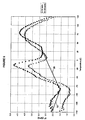
- Figure 1 shows the measured Raman spectra for a fiber material to be described below and the method of subtraction of the background and the extraction of the LAM spectrum.
- L 1 2 ⁇ c ⁇ ⁇ L ⁇ Eg c ⁇ 1 / 2
- the elastic modulus E is taken as 340 GPa as reported by Mizushima et al., J. Amer. Chem., Soc., 71, 1320 (1949 ).
- the quantity (g c E/p) 1/2 is the sonic velocity in an all trans polyethylene crystal. Based on an elastic modulus of 340 GPa, and a crystal density of 1.000 g/cm 3 , the sonic velocity is 1.844 x 10 6 cm/sec.
- F(L) The "ordered-sequence length distribution function", F(L), is calculated from the measured Raman LAM-1 spectrum by means of Eq. B.
- F L 1 - exp - hc ⁇ L kT ⁇ ⁇ L 2 ⁇ I ⁇ , arbitrary units
- a polyethylene yarn of the invention is comprised of filaments for which the peak value of F(L) is at a straight chain segment length L of at least 45 nanometers as determined at 23°C from the low frequency Raman band associated with the longitudinal acoustic mode (LAM-1).
- the peak value of F(L) preferably is at a straight chain segment length L of at least 50 nanometers, more preferably at least 55 nanometers, and most preferably 50-150 nanometers.
- DSC measurements of UHMWPE are subject to systematic errors cause by thermal lags and inefficient heat transfer.
- the DSC measurements are carried out in the following manner.
- a filament segment of about 0.03 mg mass is cut into pieces of about 5 mm length.
- the cut pieces are arranged in parallel array and wrapped in a thin Wood's metal foil and placed in an open sample pan.
- DSC measurements of such samples are made for at least three different heating rates at or below 2°K/min and the resulting measurements of the peak temperature of the first polyethylene melting endotherm are extrapolated to a heating rate of 0°K/min.
- This parameter is a measure of the number of repeating units, here taken as (-CH 2 -CH 2 -), that cooperatively participate in the melting process and is a measure of crystallite size. Higher values of ⁇ indicate longer crystalline sequences and therefore a higher degree of order.
- the "Parameter of Intrachain Cooperativity of the Melting Process” is defined herein by Eq. 9.
- ⁇ 2 ⁇ R ⁇ T m ⁇ 1 2 ⁇ ⁇ T m ⁇ 1 ⁇ ⁇ ⁇ H 0 , dimensionless where:
- the multi-filament yarns of the invention are comprised of filaments having a "Parameter of Intrachain Cooperativity of the Melting Process", v, of at least 535, preferably at least 545, more preferably at least 555, and most preferably from 545 to 1100.
- a synchrotron is used as a source of high intensity x-radiation.
- the synchrotron x-radiation is monochromatized and collimated.
- a single filament is withdrawn from the yarn to be examined and is placed in the monochromatized and collimated x-ray beam.
- the x-radiation scattered by the filament is detected by electronic or photographic means with the filament at room temperature ( ⁇ 23°C) and under no external load.
- the position and intensity of the (002) reflection of the orthorhombic polyethylene crystals are recorded. If upon scanning across the (002) reflection, the slope of scattered intensity versus scattering angle changes from positive to negative twice, i.e., if two peaks are seen in the (002) reflection, then two orthorhombic crystalline phases exist within the fiber.
- Dynamic mechanical analysis is the technique of applying a dynamic stress or strain to a sample and analyzing the response to obtain mechanical properties such as storage modulus (E'), loss modulus (E") and damping or tan delta ( ⁇ ) as a function of temperature and/or frequency.
- DMA instruments may be of different types and have different modes of operation that may effect the results obtained.
- a DMA instrument may impose a forced frequency on the sample or the instrument may be of a free resonance type.
- a forced frequency instrument may be operated in different modes (stress controlled or strain controlled). Since most dynamic mechanical analyses of polymers are run over a range of temperatures where the static force in the sample may change as a result of sample shrinkage, thermal expansion, or creep, it is necessary to have some mechanism to adjust the sample tension when temperature is changed.
- the DMA instrument may be run with a constant static force set at the start of the test to a value greater than the maximum dynamic force observed during the test. In this mode, the sample is prone to elongate as it softens on heating, resulting in a possible change in morphology.
- the DMA instrument may automatically control and adjust the static force to be a certain percent greater than the dynamic force. In this mode, the sample elongation and morphology change during the test are minimized and the DMA properties measured will be more representative of the original sample before heating.
- the inventive yarns and several prior art yarns have been characterized by DMA in a proportional force mode in tension with the static force held at 110% of dynamic force, the dynamic strain at 0.025 ⁇ 0.005%, the heating rate at 2.7 ⁇ 0.8 °C/min, and the frequency at 10 and 100 radians/sec.
- the DMA instrument employed was a model RSA II from Rheometrics Scientific (now TA Instruments, New Castle Delaware). This DMA instrument is of the strain controlled type.
- ⁇ -dispersion is defined as one occurring in a temperature region above 5°C
- a ⁇ -dispersion is one occurring in a temperature region from -70°C to 5°C
- a ⁇ -dispersion is one occurring in a temperature region from - 70°C to -120°C.
- the ⁇ -dispersion may have two components.
- the components of the ⁇ -dispersion may be a shoulder and a distinct peak or the components may be two distinct peaks.
- the integral strength of the ⁇ -dispersion is defined as the area between the DMA loss modulus plot and a base line drawn through the wings of the entire ⁇ -dispersion, measured in units of GPa-°C as illustrated in Figure 5 .
- An UHMWPE gel-spun yarn designated SPECTRA® 900 was manufactured by Honeywell International Inc. in accord with USP 4,551,296 .
- the 650 denier yarn consisting of 60 filaments had an intrinsic viscosity in decalin at 135°C of about 15 dl/g.
- the yarn tenacity was about 30 g/d as measured by ASTM D2256-02, and the yarn contained less than about 1 wt.% of other constituents.
- the yarn had been stretched in the solution state, in the gel state and after removal of the spinning solvent. The stretching conditions did not fall within the scope of equations 1 to 4, above.
- An UHMWPE gel-spun yarn designated SPECTRA® 1000 was manufactured by Honeywell International Inc. in accord with USP's 4,551,296 and 5,741,451.
- the 1300 denier yarn consisting of 240 filaments had an intrinsic viscosity in decalin at 135°C of about 14 dl/g.
- the yarn tenacity was about 35 g/d as measured by ASTM D2256-02, and the yarn contained less than 1 wt.% of other constituents.
- the yarn had been stretched in the solution state, in the gel state and after removal of the spinning solvent. The stretching conditions did not fall within the scope of equations 1 to 4, above.
- UHMWPE gel spun yarns from different lots manufactured by Honeywell International Inc. and designated either SPECTRA® 900 or SPECTRA® 1000 were characterized by Raman spectroscopy, DSC, and x-ray diffraction using the methodologies described hereinabove.
- the description of the yarns and the values of F(L) and ⁇ are listed in Table I as well as the number of peaks seen in the (002) x-ray reflection.
- An UHMWPE gel spun yarn was produced by Honeywell International Inc. in accord with USP 4,551,296 .
- the 2060 denier yarn consisting of 120 filaments had an intrinsic viscosity in decalin at 135°C of about 12 dl/g.
- the yarn tenacity was about 20 g/d as measured by ASTM D2256-02, and the yarn contained less than about 1 wt.% of other constituents.
- the yarn had been stretched between 3.5 and 8 to 1 in the solution state, between 2.4 to 4 to 1 in the gel state and between 1.05 and 1.3 to 1 after removal of the spinning solvent.
- the yarn was fed from a creel, through a set of restraining rolls at a speed (V 1 ) of about 25 meters/min into a forced convection air oven in which the internal temperature was 155 ⁇ 1°C.
- the air circulation within the oven was in a turbulent state with a time-averaged velocity in the vicinity of the yarn of about 34 meters/min.
- the feed yarn passed through the oven in a straight line from inlet to outlet over a path length (L) of 14.63 meters and thence to a second set of rolls operating at a speed ( V 2 ) of 98.8 meters/min.
- the yarn was cooled down on the second set of rolls at constant length neglecting thermal contraction.
- the yarn was thereby drawn in the oven at constant tension neglecting the effect of air drag.
- the denier per filament (dpf) was reduced from 17.2 dpf for the feed yarn to 4.34 dpf for the drawn yarn.
- Tenacity was increased from 20 g/d for the feed yarn to about 40 g/d for the drawn yarn.
- the mass throughput of drawn yarn was 5.72 grams/min per yarn end.
- filaments of the yarn of the invention had a peak value of the ordered-sequence length distribution function, F(L), at a straight chain segment length, L, greater than the prior art yarns. It is also seen that filaments of the yarn of the invention had a "Parameter of Intrachain Cooperativity of the Melting Process", v, greater than the prior art yarns. Also, this appears to be the first observation of two (002) x-ray peaks in a polyethylene filament at room temperature under no load. Table I Ex. or Comp. Ex. No. Identification Denier/Fils L, nm at peak of F(L) ⁇ , dimensionless No. of (002) X-Ray Peaks Comp. Ex.
- the yarn was subjected to dynamic mechanical analysis in tension using a Rheometrics Solids Analyzer RSA II from Rheometrics Scientific (now TA Instruments, Inc., New Castle, DE).
- the analyst entered into the instrument the frequency levels (10 and 100 radians/sec), a strain level, the proportion between the static force and the dynamic force (110%), the temperature interval between measurements (2°C), and the cross-sectional area of the yarn sample was determined from its denier (Table II).
- the DMA sample consisted of a length of the entire yarn bundle. Removal of filaments from the yarn and testing of individual filaments or fractions of the total yarn bundle is to be avoided to prevent damaging or stretching entangled filaments, thereby changing their properties. Problems of sampling yarns with non-uniform filaments across the bundle are also thereby avoided.
- the sample and instrument were cooled to the starting temperature and the instrument began measurements. It first measured yarn properties at a frequency of 10 radians/sec for a period of several seconds, averaging the measurements. Then, at the same temperature, it measured yarn properties at a frequency of 100 radians/sec for a period of several seconds averaging and recording the measurements. The instrument then ramped up the temperature 2°C, held the temperature for about 10 seconds, and then began measuring again at frequencies of 10 and 100 radians/sec. This process continued until the final temperature was reached. The average heating rate and standard deviation of heating rate during the run was 2.7 ⁇ 0.8°C/min. Because of instrument compliance the actual strain level experienced by the sample differed from the set value. The sample strain varied somewhat during a run as the temperature changed. The average strain and standard deviation was 0.025 ⁇ 0.005%.
- Plots of the loss modulus, E", versus temperature for this prior art yarn are shown in Figure 5 .
- Peaks were seen in the ⁇ -dispersion at a temperature of -125°C at a frequency of 10 radians/sec, and at a temperature of -119°C at a frequency of 100 radians/sec.
- Measurements of the heights of the ⁇ -dispersion of the loss modulus above base lines drawn through the wings of the peaks showed the amplitude of the ⁇ -dispersion to be 252 MPa at 10 radians/sec, and 432 MPa at 100 radians/sec.
- the base line 10 of the ⁇ -dispersion at 100 radians/sec is illustrated in Figure 5 .
- the ratios of the peak values of the loss moduli in the ⁇ -dispersion to the base line loss moduli at the same temperature as the peaks were 1.234:1 at 10 radians/sec and 1.241:1 at 100 radians/sec.
- the ⁇ -dispersion showed two components: low temperature shoulders at -50°C at both 10 and 100 radians/sec, and distinct peaks at - 17°C and at -14°C for 10 and 100 radians/sec respectively.
- the lower temperature component of the ⁇ -dispersion is hereinafter denoted as ⁇ (1), and the higher temperature component is denoted as ⁇ (2).
- the area between the E" plot and a base line 20 (illustrated in Figure 5 for 100 radians/sec) drawn though the wings of the ⁇ -dispersion was determined by numerical integration.
- the integral strengths of the ⁇ -dispersions were 84.9 GPa-°C and 105.3 GPa-°C at 10 and 100 radians/sec respectively.
- the ⁇ -dispersion showed peaks at 73°C and at 81°C for frequencies of 10 and 100 radians/sec respectively.
- the ratios of the peak values of the loss moduli in the ⁇ -dispersion to the base line loss moduli at the same temperature as the peaks were 1.190:1 at 10 radians/sec and 1.200:1 at 100 radians/sec.
- the ⁇ -dispersion showed ⁇ (1) peaks at -55°C and -52°C for 10 and 100 radians/sec respectively, and ⁇ (2) peaks at -21°C and -17°C for 10 and 100 radians/sec respectively.
- the integral strengths of the ⁇ -dispersions were 63.0 GPa-°C and 79.6 GPa-°C at 10 and 100 radians/sec respectively.
- the ⁇ -dispersion showed peaks at 79°C and at 93°C for frequencies of 10 and 100 radians/sec respectively.
- the ⁇ -dispersion had only one component with peaks at -38°C and at -37°C for 10 and 100 radians/sec respectively.
- the integral strengths of the ⁇ -dispersions were 53.9 GPa-°C and 60.5 GPa-°C at 10 and 100 radians/sec respectively.
- the ⁇ -dispersion shows peaks at 112°C and at 109°C for frequencies of 10 and 100 radians/sec respectively.
- the ⁇ -dispersion had only one component with peaks at -43°C and at -36°C for 10 and 100 radians/sec respectively.
- the integral strengths of the ⁇ -dispersions were 85.3 GPa-°C and 99.2 GPa-°C at 10 and 100 radians/sec respectively.
- the ⁇ -dispersion showed peaks at 78°C and at 84°C for frequencies of 10 and 100 radians/sec respectively.
- the ⁇ -dispersion had only one component with peaks at -58°C and at -50°C for 10 and 100 radians/sec respectively.
- the integral strengths of the ⁇ -dispersions were 54.4 GPa-°C and 61.1 GPa-°C at 10 and 100 radians/sec respectively.
- the ⁇ -dispersion showed peaks at 67°C and at 83°C for frequencies of 10 and 100 radians/sec respectively.
- the DMA measurements for this yarn are summarized in Table III below.
- a multi-filament polyethylene precursor yarn was gel-spun from a 10 wt.% solution as described in USP 4,551,296 . This precursor yarn had been stretched in the solution state, in the gel state and in the solid state. The draw ratio in the solid state was 2.54:1.
- the yarn of 181 filaments had a tenacity of about 15 g/d as measured by ASTM D2256-02
- This precursor yarn was fed from a creel, through a set of restraining rolls at a speed (V 1 ) of 11.1 meters/min into a forced convection air oven in which the internal temperature was 150 ⁇ 1 °C.
- the air circulation within the oven was in a turbulent state with a time-averaged velocity in the vicinity of the yarn of about 34 meters/min.
- the yarn was passed through the oven in a straight line from inlet to outlet over a path length (L) of 21.95 meters and thence to a second set of rolls operating at a speed (V 2 ) of 50 meters/min.
- the precursor yarn was thereby drawn in the oven at constant tension neglecting the effect of air drag.
- the yarn was cooled down on the second set of rolls at constant length neglecting thermal contraction producing a yarn of the invention.
- the denier per filament (dpf) was reduced from 17.7 dpf for the feed yarn to 3.82 dpf for the drawn yarn. Tenacity was increased from about 15 g/d for the feed yarn to about 41.2 g/d for the drawn yarn. The mass throughput of drawn yarn was 3.84 grams/min per yarn end. The tensile properties of this yarn are shown in Table II.
- the yarn was comprised of polyethylene having an intrinsic viscosity in decalin at 135°C; of 11.5dl/g, fewer than about 0.5 methyl groups per thousand carbon atoms, and contained less than 2 wt% of other constituents.
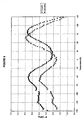
- the yarn of the invention was subjected to dynamic mechanical analysis in tension as described in Comparative Example 8. Plots of the loss modulus, E", for this yarn are shown in Figure 10 .
- a peak in the ⁇ -dispersion having a magnitude at least 100 MPa above a base line was absent at 10 radians/sec.
- a peak in the ⁇ -dispersion having a magnitude at least 130 MPa above a base line was absent at 100 radians/sec.
- the ⁇ -dispersion showed ⁇ (1) shoulders at -50°C for both 10 and 100 radians/sec respectively, and ⁇ (2) peaks at -21 °C and -17°C for 10 and 100 radians/sec respectively.
- the integral strengths of the ⁇ -dispersions were 92.5 GPa-°C and 107 GPa-°C at 10 and 100 radians/sec respectively.
- the ⁇ -dispersion was absent at a frequency of 10 radians/sec and had a peak at 123°C at 100 radians/sec.
- a multi-filament polyethylene precursor yarn was gel-spun from a 10 wt.% solution as described in USP 4,551,296 .
- This precursor yarn had been stretched in the solution state, in the gel state and in the solid state.
- the draw ratio in the solid state was 1.55:1.
- the yarn of 181 filaments had a tenacity of 15 g/d.
- This precursor yarn was fed from a creel, through a set of restraining rolls and stretched in a forced circulation air oven at conditions similar to those of Example 2.
- the drawn multi-filament yarn of the invention thereby produced possessed a tenacity of 39.7 g/d as measured by ASTM D2256-02.
- the tensile properties of this yarn are shown in Table II.
- the yarn was comprised of polyethylene having an intrinsic viscosity in decalin at 135°C of 12 dl/g, fewer than 0.5 methyl groups per thousand carbon atoms, and contained less than 2 wt% of other constituents.
- the yarn of the invention was subjected to dynamic mechanical analysis in tension as described in Comparative Example 8. Plots of the loss modulus, E", for this yarn are shown in Figure 11 .
- a peak in the ⁇ -dispersion having a magnitude at least 100 MPa above a base line was absent at 10 radians/sec.
- a peak in the ⁇ -dispersion having a magnitude at least 130 MPa above a base line was absent at 100 radians/sec.
- the ⁇ -dispersion showed ⁇ (1) shoulders at -50°C at both 10 and 100 radians/sec, and ⁇ (2) peaks at -34°C and -25°C at 10 and 100 radians/sec respectively.
- the integral strengths of the ⁇ -dispersions were 149 GPa-°C and 152 GPa-°C at 10 and 100 radians/sec respectively.
- the ⁇ -dispersion showed peaks at 74°C and at 84°C for frequencies of 10 and 100 radians/sec respectively.
- Example 3 was a complete repetition of Example 3 beginning with the preparation of the precursor yarn.
- the drawn multi-filament yarn of the invention possessed a tenacity of 38.9 g/d as measured by ASTM D2256-02.
- the tensile properties of this yarn are shown in Table II.
- the yarn was comprised of polyethylene having an intrinsic viscosity in decalin at 135°C of 12 dl/g, fewer than about 0.5 methyl groups per thousand carbon atoms, and contained less than 2 wt% of other constituents.
- the yarn of the invention was subjected to dynamic mechanical analysis in tension as described in Comparative Example 8. Plots of the loss modulus, E", for this yarn are shown in Figure 12 .
- a peak in the ⁇ -dispersion having a magnitude at least 100 MPa above a base line was absent at 10 radians/sec.
- a peak in the ⁇ -dispersion having a magnitude at least 130 MPa above a base line was absent at 100 radians/sec.
- the ⁇ -dispersion showed ⁇ (1) peaks at -50°C and -48°C for 10 and 100 radians/sec respectively, and ⁇ (2) peaks at -25°C and -22°C for 10 and 100 radians/sec respectively.
- the integral strengths of the ⁇ -dispersions were 111 GPa-°C and 135 GPa-°C at 10 and 100 radians/sec respectively.
- the ⁇ -dispersion showed peaks at 81°C and at 95°C for frequencies of 10 and 100 radians/sec respectively.
- DMA signatures of drawn multi-filament gel-spun polyethylene yarns of the invention differ from those of prior art gel-spun polyethylene yarns in one or more of the following ways, taken individually or in several combinations.
- the inventive yarns also show two components in the ⁇ -dispersion of the loss modulus.
- the essential absence of ⁇ -dispersion peak in the loss modulus for the inventive yarns is reflective of a low defect density in the crystalline phase, i.e. long runs of straight chain all trans - -(CH 2 ) n - sequences. This is consistent with the DSC evidence reported above. Accepting that the origin of the ⁇ -dispersion is molecular motion in the inter-crystalline regions, the presence of two components in the ⁇ -dispersion is believed to be reflective of the presence of two orthorhombic crystalline phases with different modes of connectivity in the inter-crystalline regions. This is consistent with the x-ray evidence reported above.
- inventive yarn described in Example 3 above was used to construct articles of the invention comprising cross-plied fiber reinforced laminates.
- Several rolls of the inventive yarn of Example 3 were suppliec from a creel and were passed through a combing station to form a unidirectional network.
- the fiber network was passed over and under stationary bars to spread the yarns into thin layers.
- the fiber network was then carried under a roll immersed in a bath of a cyclohexane solution of a KRATON® D1107 styrene-isoprene-styrene block copolymer matrix to completely coat each filament.
- the coated fiber network was passed through a squeeze roll at the exit of the bath to remove excess sealant dispersion.
- the coated fiber network was placed on a 0.35 mil (0.00089 cm) polyethylene film carrier web and passed through a heated oven to evaporate the cyclohexane and form a coherent fiber sheet containing 20% wt.% KRATON® matrix.
- the carrier web and unidirectional fiber sheet were then wound up on a roller in preparation for construction of laminates.
- a two ply laminate of the invention designated type PCR was formed by placing two rolls of the sheet material described above on the cross-plying machine described in U.S. Patent 5,173,138 .
- the carrier web was stripped off and the two unidirectional fiber sheets were cross-plied 0°/90° and consolidated at a temperature of 115°C under a pressure of 500 psi (3.5 MPa) to create a laminate.
- a four ply laminate of the invention consisting of two cross-plied fiber sheets with polyethylene films on the outside surfaces, was similarly prepared. Two rolls of the sheet material described above, including the polyethylene film carrier webs, were placed on the cross-plying machine, cross-plied 0°/90°, fiber-to-fiber, with the polyethylene carrier webs on the outside and then consolidated at a temperature of 115°C under a pressure of 500 psi (3.5 MPa) to create a laminate.
- Composite targets for ballistic testing were constructed from the above laminates.
- Rigid targets were constructed by stacking and cross-plying several layers of the PCR laminates to the desired areal density and then re-molding at a temperature of 115°C under a pressure of 500 psi (3.5 MPa).
- Flexible targets were constructed by cross-plying and loosely stacking several layers of the LCR laminates to the desired areal density.
- Ballistic testing of the laminates constructed with the inventive yarn was conducted in comparison with commercially available SPECTRA SHIELD® laminates of the same PCR and LCR types prepared from SPECTRA® 1000 yarn. The ballistic testing was conducted in accord with MIL-STD 662 E.
- V50 velocity is that velocity at which the probability that a projectile will penetrate is 50%.
- SEAC is the specific energy absorption capability of the composite per unit areal density specific to a given projectile. Its units are Joules/g/m 2 , abbreviated as J-m 2 /g.
Landscapes
- Engineering & Computer Science (AREA)
- Textile Engineering (AREA)
- Mechanical Engineering (AREA)
- Chemical & Material Sciences (AREA)
- Chemical Kinetics & Catalysis (AREA)
- General Chemical & Material Sciences (AREA)
- Artificial Filaments (AREA)
- Yarns And Mechanical Finishing Of Yarns Or Ropes (AREA)
- Knitting Of Fabric (AREA)
- Addition Polymer Or Copolymer, Post-Treatments, Or Chemical Modifications (AREA)
Claims (11)
- Multifiles Polyethylengarn, umfassend ein Polyethylen mit einer Eigenviskosität in Decalin bei 135°C von 5 dl/g bis 35 dl/g, je tausend Kohlenstoffatome weniger als zwei Methylgruppen und weniger als 2 Gew.-% an anderen Bestandteilen, wobei das multifile Garn nach ASTM D2256-02 eine Feinheitsfestigkeit von mindestens 17 g/den aufweist, wobei die Filamente des Garns in der bei 23°C aus der mit der akustischen Längsschwingung (LAM-1) assoziierte niederfrequente Ramanbande bestimmte reihenfolgebezogene Längenverteilungsfunktion F(L) einen Maximalwert bei einer geradkettigen Segmentlänge L von mindestens 40 Nanometer aufweist.
- Multifiles Polyethylengarn nach Anspruch 1, bei dem die Filamente einen Maximalwert bei einer geradkettigen Segmentlänge L von mindestens 45 Nanometer aufweisen.
- Multifiles Polyethylengarn nach Anspruch 1, bei dem die Filamente einen Maximalwert bei einer geradkettigen Segmentlänge L von mindestens 50 Nanometer aufweisen.
- Multifiles Polyethylengarn nach Anspruch 1, bei dem die Filamente einen Maximalwert bei einer geradkettigen Segmentlänge L von mindestens 55 Nanometer aufweisen.
- Multifiles Polyethylengarn nach Anspruch 1, bei dem die Filamente einen Maximalwert bei einer geradkettigen Segmentlänge L von 50 bis 150 Nanometer aufweisen.
- Multifiles Polyethylengarn nach Anspruch 1, bei dem das Garn einen durch Differential Scanning Calorimetry (DSC) an einem in etwa 5 mm lange Stücke zerschnittenen, parallel angeordnet in einer Woodschen Metallfolie eingewickelten und in einem offenen Probenpfännchen angeordneten etwa 0,03 mg schweren Filamentsegment in mindestens 3 Schmelzscans bei Heizgeschwindigkeiten von weniger als 2°K/min bei einer auf 0°K/min extrapolierten Heizgeschwindigkeit ermittelten ersten Polyethylenschmelzendotherm bestimmten Parameter der Intrakettenkooperativität des Schmelzprozesses, v, von mindestens 535 aufweist.
- Multifiles Polyethylengarn nach Anspruch 1, bei dem die Intensität des (002)-Röntgenreflexes mindestens eines Filaments des Garns, gemessen bei Raumtemperatur ohne äußere Belastung, zwei deutliche Maxima zeigt.
- Multifiles Polyethylengarn nach Anspruch 1, bei dem die Filamente des Garnsa) bei der Intensität des (002)-Röntgenreflexes, gemessen bei Raumtemperatur ohne äußere Belastung, zwei deutliche Maxima undb) einen durch Differential Scanning Calorimetry (DSC) an einem in etwa 5 mm lange Stücke zerschnittenen, parallel angeordnet in einer Woodschen Metallfolie eingewickelten und in einem offenen Probenpfännchen angeordneten etwa 0,03 mg schweren Filamentsegment in mindestens 3 Schmelzscans bei Heizgeschwindigkeiten von weniger als 2°K/min bei einer auf 0°K/min extrapolierten Heizgeschwindigkeit ermittelten ersten Polyethylenschmelzendotherm bestimmten Parameter der Intrakettenkooperativität des Schmelzprozesses, v, von mindestens 535 aufweisen.
- Erzeugnis, umfassend ein verstrecktes Polyethylenmultifilamentgarn gemäß einem der Ansprüche 1-8.
- Erzeugnis nach Anspruch 9, umfassend mindestens ein Netz der verstreckten Polyethylenmultifilamentgarne.
- Erzeugnis nach Anspruch 10, umfassend mehrere Netze der verstreckten Polyethylenmultifilamentgarne, wobei die Netze in uniaxialen Schichten angeordnet sind, wobei die Faserrichtung einer Schicht jeweils unter einem Winkel gegenüber der Faserrichtung benachbarter Lagen verläuft.
Applications Claiming Priority (3)
| Application Number | Priority Date | Filing Date | Title |
|---|---|---|---|
| US10/934,675 US6969553B1 (en) | 2004-09-03 | 2004-09-03 | Drawn gel-spun polyethylene yarns and process for drawing |
| US11/206,838 US7223470B2 (en) | 2005-08-19 | 2005-08-19 | Drawn gel-spun polyethylene yarns |
| EP05857934A EP1802790B1 (de) | 2004-09-03 | 2005-09-01 | Gezogene gelfaserpolyethylengarne und ziehverfahren |
Related Parent Applications (2)
| Application Number | Title | Priority Date | Filing Date |
|---|---|---|---|
| EP05857934A Division EP1802790B1 (de) | 2004-09-03 | 2005-09-01 | Gezogene gelfaserpolyethylengarne und ziehverfahren |
| EP05857934.3 Division | 2005-09-01 |
Publications (2)
| Publication Number | Publication Date |
|---|---|
| EP2028295A1 EP2028295A1 (de) | 2009-02-25 |
| EP2028295B1 true EP2028295B1 (de) | 2010-08-25 |
Family
ID=37101610
Family Applications (4)
| Application Number | Title | Priority Date | Filing Date |
|---|---|---|---|
| EP08018825A Active EP2028295B1 (de) | 2004-09-03 | 2005-09-01 | Polyethylengarne |
| EP05857934A Not-in-force EP1802790B1 (de) | 2004-09-03 | 2005-09-01 | Gezogene gelfaserpolyethylengarne und ziehverfahren |
| EP08018824A Withdrawn EP2028294A1 (de) | 2004-09-03 | 2005-09-01 | Polyethylen |
| EP08018823A Active EP2028293B1 (de) | 2004-09-03 | 2005-09-01 | Polyethylengarne |
Family Applications After (3)
| Application Number | Title | Priority Date | Filing Date |
|---|---|---|---|
| EP05857934A Not-in-force EP1802790B1 (de) | 2004-09-03 | 2005-09-01 | Gezogene gelfaserpolyethylengarne und ziehverfahren |
| EP08018824A Withdrawn EP2028294A1 (de) | 2004-09-03 | 2005-09-01 | Polyethylen |
| EP08018823A Active EP2028293B1 (de) | 2004-09-03 | 2005-09-01 | Polyethylengarne |
Country Status (14)
| Country | Link |
|---|---|
| EP (4) | EP2028295B1 (de) |
| JP (1) | JP5324096B2 (de) |
| KR (1) | KR101247969B1 (de) |
| CN (1) | CN103696027B (de) |
| AR (1) | AR050725A1 (de) |
| AT (3) | ATE478985T1 (de) |
| CA (1) | CA2580115C (de) |
| DE (3) | DE602005015741D1 (de) |
| ES (1) | ES2328948T3 (de) |
| IL (1) | IL181693A0 (de) |
| MX (1) | MX2007002648A (de) |
| RU (1) | RU2388856C2 (de) |
| TW (1) | TWI339691B (de) |
| WO (1) | WO2006124054A2 (de) |
Families Citing this family (18)
| Publication number | Priority date | Publication date | Assignee | Title |
|---|---|---|---|---|
| US7638191B2 (en) * | 2007-06-08 | 2009-12-29 | Honeywell International Inc. | High tenacity polyethylene yarn |
| US8747715B2 (en) * | 2007-06-08 | 2014-06-10 | Honeywell International Inc | Ultra-high strength UHMW PE fibers and products |
| US10330581B2 (en) | 2007-09-17 | 2019-06-25 | Rave Llc | Debris removal from high aspect structures |
| US10384238B2 (en) | 2007-09-17 | 2019-08-20 | Rave Llc | Debris removal in high aspect structures |
| WO2009068985A2 (en) | 2007-11-29 | 2009-06-04 | Telefonaktiebolaget L M Ericsson (Publ) | End-to-edge media protection |
| US8697220B2 (en) * | 2009-08-11 | 2014-04-15 | Honeywell International, Inc. | High strength tape articles from ultra-high molecular weight polyethylene |
| US8236119B2 (en) * | 2009-08-11 | 2012-08-07 | Honeywell International Inc. | High strength ultra-high molecular weight polyethylene tape articles |
| ES2714003T3 (es) * | 2011-12-14 | 2019-05-24 | Dsm Ip Assets Bv | Hilo multifilamentos de polietileno de peso molecular ultra elevado |
| CN102532667B (zh) * | 2012-01-09 | 2013-03-13 | 王龙 | 一种可组合的船体生产方法 |
| US9169581B2 (en) * | 2012-02-24 | 2015-10-27 | Honeywell International Inc. | High tenacity high modulus UHMW PE fiber and the process of making |
| KR101440570B1 (ko) | 2012-11-29 | 2014-09-17 | 주식회사 삼양사 | 폴리에틸렌 섬유 및 그의 제조방법 |
| KR101456919B1 (ko) * | 2014-06-05 | 2014-10-31 | 동명기술 주식회사 | 원사의 제조 방법 |
| JP6582433B2 (ja) * | 2015-02-20 | 2019-10-02 | 東洋紡株式会社 | マルチフィラメント |
| JP6582434B2 (ja) * | 2015-02-20 | 2019-10-02 | 東洋紡株式会社 | 組紐 |
| WO2016133102A1 (ja) * | 2015-02-20 | 2016-08-25 | 東洋紡株式会社 | マルチフィラメント及びそれを用いた組紐 |
| TWI841110B (zh) * | 2016-05-20 | 2024-05-01 | 美商布魯克奈米股份有限公司 | 從高深寬比結構移除碎片 |
| US11306432B2 (en) * | 2018-11-05 | 2022-04-19 | Honeywell International Inc. | HMPE fiber with improved bending fatigue performance |
| US20230392296A1 (en) * | 2020-10-08 | 2023-12-07 | Kolon Industries, Inc. | High-strength polyethylene yarn with improved shrinkage rate and manufacturing method therefor |
Family Cites Families (15)
| Publication number | Priority date | Publication date | Assignee | Title |
|---|---|---|---|---|
| US4551296A (en) | 1982-03-19 | 1985-11-05 | Allied Corporation | Producing high tenacity, high modulus crystalline article such as fiber or film |
| JPS60167918A (ja) * | 1984-02-06 | 1985-08-31 | Kuraray Co Ltd | 高強力ポリエチレン繊維の延伸方法 |
| JPS60239509A (ja) * | 1984-05-04 | 1985-11-28 | Toray Ind Inc | 高強度高モジユラスポリオレフイン系繊維の製造方法 |
| US4663101A (en) * | 1985-01-11 | 1987-05-05 | Allied Corporation | Shaped polyethylene articles of intermediate molecular weight and high modulus |
| JPH06102846B2 (ja) * | 1985-05-01 | 1994-12-14 | 三井石油化学工業株式会社 | 超高分子量ポリエチレン延伸物の製造方法 |
| EP0205960B1 (de) | 1985-06-17 | 1990-10-24 | AlliedSignal Inc. | Polyolefinfaser mit hoher Festigkeit, niedrigem Schrumpfen, ultrahohem Modul, sehr niedrigem Kriechen und mit guter Festigkeitserhaltung bei hoher Temperatur sowie Verfahren zu deren Herstellung |
| JPS6241341A (ja) * | 1985-08-08 | 1987-02-23 | 東洋紡績株式会社 | ゲル繊維の高速延伸方法 |
| US5173138A (en) | 1990-08-08 | 1992-12-22 | Blauch Denise A | Method and apparatus for the continuous production of cross-plied material |
| US5505900A (en) * | 1993-07-09 | 1996-04-09 | Suwanda; Dedo | Continuous process for manufacture of crosslinked, oriented polyethylene extrudates |
| JP2699319B2 (ja) * | 1993-12-16 | 1998-01-19 | 東洋紡績株式会社 | 高強度ポリエチレン繊維 |
| NL1010413C1 (nl) * | 1998-10-28 | 2000-05-01 | Dsm Nv | Hooggeoriënteerde polyolefinevezel. |
| US6448359B1 (en) * | 2000-03-27 | 2002-09-10 | Honeywell International Inc. | High tenacity, high modulus filament |
| US6448659B1 (en) | 2000-04-26 | 2002-09-10 | Advanced Micro Devices, Inc. | Stacked die design with supporting O-ring |
| NL1016356C2 (nl) | 2000-10-09 | 2002-04-10 | Dsm Nv | Oven voor het op verhoogde temperatuur verstrekken van vezels. |
| US7344668B2 (en) | 2003-10-31 | 2008-03-18 | Honeywell International Inc. | Process for drawing gel-spun polyethylene yarns |
-
2005
- 2005-09-01 DE DE602005015741T patent/DE602005015741D1/de active Active
- 2005-09-01 DE DE602005023233T patent/DE602005023233D1/de active Active
- 2005-09-01 CN CN201310660923.5A patent/CN103696027B/zh active Active
- 2005-09-01 WO PCT/US2005/031496 patent/WO2006124054A2/en active Application Filing
- 2005-09-01 AT AT08018825T patent/ATE478985T1/de not_active IP Right Cessation
- 2005-09-01 EP EP08018825A patent/EP2028295B1/de active Active
- 2005-09-01 EP EP05857934A patent/EP1802790B1/de not_active Not-in-force
- 2005-09-01 AT AT08018823T patent/ATE478984T1/de not_active IP Right Cessation
- 2005-09-01 CA CA2580115A patent/CA2580115C/en not_active Expired - Fee Related
- 2005-09-01 EP EP08018824A patent/EP2028294A1/de not_active Withdrawn
- 2005-09-01 MX MX2007002648A patent/MX2007002648A/es active IP Right Grant
- 2005-09-01 ES ES05857934T patent/ES2328948T3/es active Active
- 2005-09-01 KR KR1020077007655A patent/KR101247969B1/ko active IP Right Grant
- 2005-09-01 DE DE602005023231T patent/DE602005023231D1/de active Active
- 2005-09-01 EP EP08018823A patent/EP2028293B1/de active Active
- 2005-09-01 JP JP2007530438A patent/JP5324096B2/ja not_active Expired - Fee Related
- 2005-09-01 RU RU2007112312/12A patent/RU2388856C2/ru not_active IP Right Cessation
- 2005-09-01 AT AT05857934T patent/ATE437982T1/de not_active IP Right Cessation
- 2005-09-02 TW TW094130202A patent/TWI339691B/zh not_active IP Right Cessation
- 2005-09-05 AR ARP050103706A patent/AR050725A1/es not_active Application Discontinuation
-
2007
- 2007-03-04 IL IL181693A patent/IL181693A0/en not_active IP Right Cessation
Also Published As
| Publication number | Publication date |
|---|---|
| EP2028293B1 (de) | 2010-08-25 |
| CN103696027B (zh) | 2016-05-25 |
| RU2007112312A (ru) | 2008-10-20 |
| DE602005023233D1 (de) | 2010-10-07 |
| MX2007002648A (es) | 2007-05-15 |
| TW200622047A (en) | 2006-07-01 |
| ES2328948T3 (es) | 2009-11-19 |
| IL181693A0 (en) | 2007-07-04 |
| EP1802790B1 (de) | 2009-07-29 |
| ATE478984T1 (de) | 2010-09-15 |
| EP2028293A1 (de) | 2009-02-25 |
| JP5324096B2 (ja) | 2013-10-23 |
| JP2008512573A (ja) | 2008-04-24 |
| KR101247969B1 (ko) | 2013-04-10 |
| KR20070101836A (ko) | 2007-10-17 |
| CN103696027A (zh) | 2014-04-02 |
| CA2580115A1 (en) | 2006-11-23 |
| AR050725A1 (es) | 2006-11-15 |
| ATE437982T1 (de) | 2009-08-15 |
| ATE478985T1 (de) | 2010-09-15 |
| DE602005015741D1 (de) | 2009-09-10 |
| WO2006124054A2 (en) | 2006-11-23 |
| WO2006124054A3 (en) | 2007-01-04 |
| EP2028295A1 (de) | 2009-02-25 |
| EP2028294A1 (de) | 2009-02-25 |
| TWI339691B (en) | 2011-04-01 |
| EP1802790A2 (de) | 2007-07-04 |
| RU2388856C2 (ru) | 2010-05-10 |
| CA2580115C (en) | 2011-04-05 |
| DE602005023231D1 (de) | 2010-10-07 |
Similar Documents
| Publication | Publication Date | Title |
|---|---|---|
| EP2028295B1 (de) | Polyethylengarne | |
| US7078099B1 (en) | Drawn gel-spun polyethylene yarns and process for drawing | |
| EP2300644B1 (de) | Verfahren zur herstellung von polyethylenfasern mit hohem molekulargewicht | |
| US7370395B2 (en) | Heating apparatus and process for drawing polyolefin fibers | |
| US20050093200A1 (en) | Process for drawing gel-spun polyethylene yarns | |
| US7384691B2 (en) | Drawn gel-spun polyethylene yarns | |
| JP2007522351A (ja) | 高性能ポリエチレン・マルチフィラメント糸の製造方法 | |
| JPH0349747B2 (de) | ||
| Long et al. | Tensile drawing behaviour of polyethylene terephthalate | |
| MX2008007956A (en) | Heating apparatus and process for drawing polyolefin fibers |
Legal Events
| Date | Code | Title | Description |
|---|---|---|---|
| PUAI | Public reference made under article 153(3) epc to a published international application that has entered the european phase |
Free format text: ORIGINAL CODE: 0009012 |
|
| AC | Divisional application: reference to earlier application |
Ref document number: 1802790 Country of ref document: EP Kind code of ref document: P |
|
| AK | Designated contracting states |
Kind code of ref document: A1 Designated state(s): AT BE BG CH CY CZ DE DK EE ES FI FR GB GR HU IE IS IT LI LT LU LV MC NL PL PT RO SE SI SK TR |
|
| RIN1 | Information on inventor provided before grant (corrected) |
Inventor name: TAM, THOMAS YIU-TAI Inventor name: TAN, CHOK B. Inventor name: ARNETT, CHARLES R. Inventor name: ZHOU, QUANG Inventor name: MOORE, RONALD A. Inventor name: TWOMEY, CONOR J. |
|
| 17P | Request for examination filed |
Effective date: 20090817 |
|
| 17Q | First examination report despatched |
Effective date: 20090915 |
|
| AKX | Designation fees paid |
Designated state(s): AT BE BG CH CY CZ DE DK EE ES FI FR GB GR HU IE IS IT LI LT LU LV MC NL PL PT RO SE SI SK TR |
|
| GRAP | Despatch of communication of intention to grant a patent |
Free format text: ORIGINAL CODE: EPIDOSNIGR1 |
|
| GRAS | Grant fee paid |
Free format text: ORIGINAL CODE: EPIDOSNIGR3 |
|
| GRAA | (expected) grant |
Free format text: ORIGINAL CODE: 0009210 |
|
| AC | Divisional application: reference to earlier application |
Ref document number: 1802790 Country of ref document: EP Kind code of ref document: P |
|
| AK | Designated contracting states |
Kind code of ref document: B1 Designated state(s): AT BE BG CH CY CZ DE DK EE ES FI FR GB GR HU IE IS IT LI LT LU LV MC NL PL PT RO SE SI SK TR |
|
| REG | Reference to a national code |
Ref country code: GB Ref legal event code: FG4D |
|
| REG | Reference to a national code |
Ref country code: CH Ref legal event code: EP |
|
| REG | Reference to a national code |
Ref country code: IE Ref legal event code: FG4D |
|
| REF | Corresponds to: |
Ref document number: 602005023233 Country of ref document: DE Date of ref document: 20101007 Kind code of ref document: P |
|
| REG | Reference to a national code |
Ref country code: NL Ref legal event code: T3 |
|
| REG | Reference to a national code |
Ref country code: ES Ref legal event code: FG2A Effective date: 20110111 |
|
| LTIE | Lt: invalidation of european patent or patent extension |
Effective date: 20100825 |
|
| PG25 | Lapsed in a contracting state [announced via postgrant information from national office to epo] |
Ref country code: AT Free format text: LAPSE BECAUSE OF FAILURE TO SUBMIT A TRANSLATION OF THE DESCRIPTION OR TO PAY THE FEE WITHIN THE PRESCRIBED TIME-LIMIT Effective date: 20100825 Ref country code: LT Free format text: LAPSE BECAUSE OF FAILURE TO SUBMIT A TRANSLATION OF THE DESCRIPTION OR TO PAY THE FEE WITHIN THE PRESCRIBED TIME-LIMIT Effective date: 20100825 Ref country code: FI Free format text: LAPSE BECAUSE OF FAILURE TO SUBMIT A TRANSLATION OF THE DESCRIPTION OR TO PAY THE FEE WITHIN THE PRESCRIBED TIME-LIMIT Effective date: 20100825 |
|
| PG25 | Lapsed in a contracting state [announced via postgrant information from national office to epo] |
Ref country code: SI Free format text: LAPSE BECAUSE OF FAILURE TO SUBMIT A TRANSLATION OF THE DESCRIPTION OR TO PAY THE FEE WITHIN THE PRESCRIBED TIME-LIMIT Effective date: 20100825 Ref country code: BG Free format text: LAPSE BECAUSE OF FAILURE TO SUBMIT A TRANSLATION OF THE DESCRIPTION OR TO PAY THE FEE WITHIN THE PRESCRIBED TIME-LIMIT Effective date: 20101125 Ref country code: CY Free format text: LAPSE BECAUSE OF FAILURE TO SUBMIT A TRANSLATION OF THE DESCRIPTION OR TO PAY THE FEE WITHIN THE PRESCRIBED TIME-LIMIT Effective date: 20100825 Ref country code: IS Free format text: LAPSE BECAUSE OF FAILURE TO SUBMIT A TRANSLATION OF THE DESCRIPTION OR TO PAY THE FEE WITHIN THE PRESCRIBED TIME-LIMIT Effective date: 20101225 Ref country code: PL Free format text: LAPSE BECAUSE OF FAILURE TO SUBMIT A TRANSLATION OF THE DESCRIPTION OR TO PAY THE FEE WITHIN THE PRESCRIBED TIME-LIMIT Effective date: 20100825 Ref country code: PT Free format text: LAPSE BECAUSE OF FAILURE TO SUBMIT A TRANSLATION OF THE DESCRIPTION OR TO PAY THE FEE WITHIN THE PRESCRIBED TIME-LIMIT Effective date: 20101227 |
|
| PG25 | Lapsed in a contracting state [announced via postgrant information from national office to epo] |
Ref country code: SE Free format text: LAPSE BECAUSE OF FAILURE TO SUBMIT A TRANSLATION OF THE DESCRIPTION OR TO PAY THE FEE WITHIN THE PRESCRIBED TIME-LIMIT Effective date: 20100825 Ref country code: GR Free format text: LAPSE BECAUSE OF FAILURE TO SUBMIT A TRANSLATION OF THE DESCRIPTION OR TO PAY THE FEE WITHIN THE PRESCRIBED TIME-LIMIT Effective date: 20101126 Ref country code: LV Free format text: LAPSE BECAUSE OF FAILURE TO SUBMIT A TRANSLATION OF THE DESCRIPTION OR TO PAY THE FEE WITHIN THE PRESCRIBED TIME-LIMIT Effective date: 20100825 Ref country code: BE Free format text: LAPSE BECAUSE OF FAILURE TO SUBMIT A TRANSLATION OF THE DESCRIPTION OR TO PAY THE FEE WITHIN THE PRESCRIBED TIME-LIMIT Effective date: 20100825 |
|
| PG25 | Lapsed in a contracting state [announced via postgrant information from national office to epo] |
Ref country code: DK Free format text: LAPSE BECAUSE OF FAILURE TO SUBMIT A TRANSLATION OF THE DESCRIPTION OR TO PAY THE FEE WITHIN THE PRESCRIBED TIME-LIMIT Effective date: 20100825 Ref country code: MC Free format text: LAPSE BECAUSE OF NON-PAYMENT OF DUE FEES Effective date: 20100930 |
|
| REG | Reference to a national code |
Ref country code: CH Ref legal event code: PL |
|
| PG25 | Lapsed in a contracting state [announced via postgrant information from national office to epo] |
Ref country code: EE Free format text: LAPSE BECAUSE OF FAILURE TO SUBMIT A TRANSLATION OF THE DESCRIPTION OR TO PAY THE FEE WITHIN THE PRESCRIBED TIME-LIMIT Effective date: 20100825 Ref country code: RO Free format text: LAPSE BECAUSE OF FAILURE TO SUBMIT A TRANSLATION OF THE DESCRIPTION OR TO PAY THE FEE WITHIN THE PRESCRIBED TIME-LIMIT Effective date: 20100825 Ref country code: CZ Free format text: LAPSE BECAUSE OF FAILURE TO SUBMIT A TRANSLATION OF THE DESCRIPTION OR TO PAY THE FEE WITHIN THE PRESCRIBED TIME-LIMIT Effective date: 20100825 Ref country code: SK Free format text: LAPSE BECAUSE OF FAILURE TO SUBMIT A TRANSLATION OF THE DESCRIPTION OR TO PAY THE FEE WITHIN THE PRESCRIBED TIME-LIMIT Effective date: 20100825 |
|
| PLBE | No opposition filed within time limit |
Free format text: ORIGINAL CODE: 0009261 |
|
| STAA | Information on the status of an ep patent application or granted ep patent |
Free format text: STATUS: NO OPPOSITION FILED WITHIN TIME LIMIT |
|
| PG25 | Lapsed in a contracting state [announced via postgrant information from national office to epo] |
Ref country code: LI Free format text: LAPSE BECAUSE OF NON-PAYMENT OF DUE FEES Effective date: 20100930 Ref country code: CH Free format text: LAPSE BECAUSE OF NON-PAYMENT OF DUE FEES Effective date: 20100930 Ref country code: IE Free format text: LAPSE BECAUSE OF NON-PAYMENT OF DUE FEES Effective date: 20100901 |
|
| 26N | No opposition filed |
Effective date: 20110526 |
|
| REG | Reference to a national code |
Ref country code: DE Ref legal event code: R097 Ref document number: 602005023233 Country of ref document: DE Effective date: 20110526 |
|
| PG25 | Lapsed in a contracting state [announced via postgrant information from national office to epo] |
Ref country code: LU Free format text: LAPSE BECAUSE OF NON-PAYMENT OF DUE FEES Effective date: 20100901 Ref country code: HU Free format text: LAPSE BECAUSE OF FAILURE TO SUBMIT A TRANSLATION OF THE DESCRIPTION OR TO PAY THE FEE WITHIN THE PRESCRIBED TIME-LIMIT Effective date: 20110226 |
|
| PG25 | Lapsed in a contracting state [announced via postgrant information from national office to epo] |
Ref country code: TR Free format text: LAPSE BECAUSE OF FAILURE TO SUBMIT A TRANSLATION OF THE DESCRIPTION OR TO PAY THE FEE WITHIN THE PRESCRIBED TIME-LIMIT Effective date: 20100825 |
|
| REG | Reference to a national code |
Ref country code: FR Ref legal event code: PLFP Year of fee payment: 12 |
|
| REG | Reference to a national code |
Ref country code: FR Ref legal event code: PLFP Year of fee payment: 13 |
|
| REG | Reference to a national code |
Ref country code: FR Ref legal event code: PLFP Year of fee payment: 14 |
|
| PGFP | Annual fee paid to national office [announced via postgrant information from national office to epo] |
Ref country code: GB Payment date: 20180928 Year of fee payment: 14 |
|
| PGFP | Annual fee paid to national office [announced via postgrant information from national office to epo] |
Ref country code: DE Payment date: 20181130 Year of fee payment: 14 |
|
| PGFP | Annual fee paid to national office [announced via postgrant information from national office to epo] |
Ref country code: ES Payment date: 20181024 Year of fee payment: 14 Ref country code: FR Payment date: 20181001 Year of fee payment: 14 Ref country code: IT Payment date: 20180927 Year of fee payment: 14 |
|
| REG | Reference to a national code |
Ref country code: DE Ref legal event code: R119 Ref document number: 602005023233 Country of ref document: DE |
|
| PG25 | Lapsed in a contracting state [announced via postgrant information from national office to epo] |
Ref country code: DE Free format text: LAPSE BECAUSE OF NON-PAYMENT OF DUE FEES Effective date: 20200401 |
|
| PG25 | Lapsed in a contracting state [announced via postgrant information from national office to epo] |
Ref country code: IT Free format text: LAPSE BECAUSE OF NON-PAYMENT OF DUE FEES Effective date: 20190901 |
|
| GBPC | Gb: european patent ceased through non-payment of renewal fee |
Effective date: 20190901 |
|
| PG25 | Lapsed in a contracting state [announced via postgrant information from national office to epo] |
Ref country code: FR Free format text: LAPSE BECAUSE OF NON-PAYMENT OF DUE FEES Effective date: 20190930 Ref country code: GB Free format text: LAPSE BECAUSE OF NON-PAYMENT OF DUE FEES Effective date: 20190901 |
|
| REG | Reference to a national code |
Ref country code: ES Ref legal event code: FD2A Effective date: 20210127 |
|
| PG25 | Lapsed in a contracting state [announced via postgrant information from national office to epo] |
Ref country code: ES Free format text: LAPSE BECAUSE OF NON-PAYMENT OF DUE FEES Effective date: 20190902 |
|
| P01 | Opt-out of the competence of the unified patent court (upc) registered |
Effective date: 20230414 |
|
| PGFP | Annual fee paid to national office [announced via postgrant information from national office to epo] |
Ref country code: NL Payment date: 20240925 Year of fee payment: 20 |