EP2028126B1 - Support avec poignée - Google Patents
Support avec poignée Download PDFInfo
- Publication number
- EP2028126B1 EP2028126B1 EP20080013311 EP08013311A EP2028126B1 EP 2028126 B1 EP2028126 B1 EP 2028126B1 EP 20080013311 EP20080013311 EP 20080013311 EP 08013311 A EP08013311 A EP 08013311A EP 2028126 B1 EP2028126 B1 EP 2028126B1
- Authority
- EP
- European Patent Office
- Prior art keywords
- handle
- carrying handle
- containers
- carrying
- elements
- Prior art date
- Legal status (The legal status is an assumption and is not a legal conclusion. Google has not performed a legal analysis and makes no representation as to the accuracy of the status listed.)
- Not-in-force
Links
- 238000004806 packaging method and process Methods 0.000 claims description 17
- 239000011049 pearl Substances 0.000 claims description 2
- 230000002787 reinforcement Effects 0.000 claims 3
- 210000003739 neck Anatomy 0.000 description 25
- 239000000463 material Substances 0.000 description 12
- 230000003014 reinforcing effect Effects 0.000 description 10
- 210000003811 finger Anatomy 0.000 description 8
- 239000004033 plastic Substances 0.000 description 7
- 229920003023 plastic Polymers 0.000 description 7
- 235000013361 beverage Nutrition 0.000 description 6
- 238000005452 bending Methods 0.000 description 4
- 210000003813 thumb Anatomy 0.000 description 4
- 229920001903 high density polyethylene Polymers 0.000 description 3
- 239000004700 high-density polyethylene Substances 0.000 description 3
- 230000006978 adaptation Effects 0.000 description 2
- 239000000969 carrier Substances 0.000 description 2
- 239000013013 elastic material Substances 0.000 description 2
- 239000011888 foil Substances 0.000 description 2
- 230000002093 peripheral effect Effects 0.000 description 2
- WYTGDNHDOZPMIW-RCBQFDQVSA-N alstonine Natural products C1=CC2=C3C=CC=CC3=NC2=C2N1C[C@H]1[C@H](C)OC=C(C(=O)OC)[C@H]1C2 WYTGDNHDOZPMIW-RCBQFDQVSA-N 0.000 description 1
- 238000013459 approach Methods 0.000 description 1
- 239000011324 bead Substances 0.000 description 1
- 230000009286 beneficial effect Effects 0.000 description 1
- 210000000078 claw Anatomy 0.000 description 1
- 230000006835 compression Effects 0.000 description 1
- 238000007906 compression Methods 0.000 description 1
- 230000001419 dependent effect Effects 0.000 description 1
- 238000001514 detection method Methods 0.000 description 1
- 238000011161 development Methods 0.000 description 1
- 230000018109 developmental process Effects 0.000 description 1
- 230000000694 effects Effects 0.000 description 1
- 238000000605 extraction Methods 0.000 description 1
- 239000012530 fluid Substances 0.000 description 1
- 210000005224 forefinger Anatomy 0.000 description 1
- 238000002347 injection Methods 0.000 description 1
- 239000007924 injection Substances 0.000 description 1
- 238000003780 insertion Methods 0.000 description 1
- 230000037431 insertion Effects 0.000 description 1
- 230000013011 mating Effects 0.000 description 1
- 239000002184 metal Substances 0.000 description 1
- 238000000034 method Methods 0.000 description 1
- 238000012986 modification Methods 0.000 description 1
- 230000004048 modification Effects 0.000 description 1
- 238000000465 moulding Methods 0.000 description 1
- 239000002985 plastic film Substances 0.000 description 1
- 239000012858 resilient material Substances 0.000 description 1
- 238000000926 separation method Methods 0.000 description 1
- 229920006300 shrink film Polymers 0.000 description 1
- 239000003381 stabilizer Substances 0.000 description 1
- 230000000087 stabilizing effect Effects 0.000 description 1
- 239000000725 suspension Substances 0.000 description 1
Images

Classifications
-
- B—PERFORMING OPERATIONS; TRANSPORTING
- B65—CONVEYING; PACKING; STORING; HANDLING THIN OR FILAMENTARY MATERIAL
- B65D—CONTAINERS FOR STORAGE OR TRANSPORT OF ARTICLES OR MATERIALS, e.g. BAGS, BARRELS, BOTTLES, BOXES, CANS, CARTONS, CRATES, DRUMS, JARS, TANKS, HOPPERS, FORWARDING CONTAINERS; ACCESSORIES, CLOSURES, OR FITTINGS THEREFOR; PACKAGING ELEMENTS; PACKAGES
- B65D71/00—Bundles of articles held together by packaging elements for convenience of storage or transport, e.g. portable segregating carrier for plural receptacles such as beer cans or pop bottles; Bales of material
- B65D71/50—Bundles of articles held together by packaging elements for convenience of storage or transport, e.g. portable segregating carrier for plural receptacles such as beer cans or pop bottles; Bales of material comprising a plurality of articles held together only partially by packaging elements formed otherwise than by folding a blank
-
- B—PERFORMING OPERATIONS; TRANSPORTING
- B65—CONVEYING; PACKING; STORING; HANDLING THIN OR FILAMENTARY MATERIAL
- B65D—CONTAINERS FOR STORAGE OR TRANSPORT OF ARTICLES OR MATERIALS, e.g. BAGS, BARRELS, BOTTLES, BOXES, CANS, CARTONS, CRATES, DRUMS, JARS, TANKS, HOPPERS, FORWARDING CONTAINERS; ACCESSORIES, CLOSURES, OR FITTINGS THEREFOR; PACKAGING ELEMENTS; PACKAGES
- B65D2203/00—Decoration means, markings, information elements, contents indicators
- B65D2203/06—Arrangements on packages concerning bar-codes
Definitions
- the invention relates to a carrying handle for a plurality of containers with a handle member and receiving elements for receiving the container, wherein the handle member extends between the receiving elements and is arranged parallel to the plane of the carrying handle telescopically liftable over at least two places on the carrying handle, and a packaging unit of a Carrying handle and at least two containers.
- a container package for holding and carrying a plurality of containers, bottles, and the like, and a method for assembling the same, and a package for a group of containers each having a neck portion.
- the juxtaposed containers each have a body portion and a neck portion projecting upwardly and inwardly therefrom, which is smaller than the body portion, the containers being arranged side by side in parallel with each other in a grape-shaped group.
- an elastic support is slid with a plurality of for accommodating the neck portion of a respective container serving constricting recesses whose mutual center distances are smaller as the center distances between corresponding abutting containers, whereby the foot portions of the containers are applied to the outside with respect to the container group.
- an elastic endless belt is guided around, through which the foot portion of the Container resiliently acted upon in a laterally abutting position. The carrier and the endless belt are under a sufficiently high tension to hold the containers in the package.
- a bottle carrier for collectively detecting at least two bottles, which are in particular beverage bottles known.
- the bottleneck are provided below its bead partially embracing approaches.
- the bottle carrier is made of a resilient material, such as plastic.
- the DE 25 31 325 A1 discloses a container package having a plurality of containers disposed substantially adjacent to one another and divided into a plurality of groups, each comprising at least two containers.
- An upper support member includes and secures first end portions of each container, whereas a second sheet or foil support portion has interconnected portions.
- the container package includes and holds each container group.
- the interconnected parts of the second sheet or foil support member include band portions comprising two containers without extending between the two containers.
- the upper support member has two openings for engagement with the thumb and a finger to allow the container packaging to be carried.
- the carrier itself comprises a structural frame carrying a plurality of collars, each of which can receive the neck of a container and engage with the projection located on the periphery of the container. Further, each collar has a resilient edge depending therefrom which cooperates with a portion of the outer surface of the respective container to prevent relative movement between the container and the carrier.
- the collars have a plurality of spaced apart resilient tabs or tabs which engage the projections of the containers. For wear, the wearer has two openings in which can be grasped with thumb and a finger to carry the container packaging or the carrier.
- an elongated support body which has a support bracket above the support body and on its underside at least two hanging rail-like receptacles for receiving a plurality of bottles in a row.
- individual receptacles arranged at a distance in the longitudinal direction can also be provided for accommodating only one bottle at a time.
- the recordings are closed at one end or provided with a stop stop and at the other end for the bottle supply educated.
- a holding member for securing the respective bottle necks is also provided in the receptacle.
- a container carrier which has a flexible platform.
- This includes a container engaging portion having an opening through the platform for receiving the neck of a container, a handle portion having a base extending transversely to a longitudinal axis of the platform, a pair of handle legs, the proximal ends of the handle legs integrally formed with the ends of the base member are.
- the distal ends of the handle leg are integral with the container engaging portion at opposite points on the container engaging portion and having a flange integral with the base member and extending inwardly from the base member over substantially the length of the base member.
- the inner periphery of the The container engaging portion and the handle portion provide an opening to allow the fingers of a user to engage.
- the flange has transverse fold lines formed in the surface of the platform. In this way, a bending of the handle portion to its gripping is possible.
- the DE 20 2005 005 970 U1 discloses a bottle feeder for PET returnable bottles, which consists of the same material as the returnable bottles themselves and has six punched holes for receiving the bottle necks or bottle heads.
- Thestationnbündler is U-shaped from a strong plastic sheet.
- the DE 20 2005 014 112 U1 discloses a carrying handle having a substantially plate-shaped support member, at the lateral peripheral edge of which a plurality of snap-in devices for snapping and holding objects are provided spaced therefrom. These snap-in devices are designed like a claw. Furthermore, the carrying handle has a rigid, upwardly projecting handle, which is formed integrally with the carrier element. As a common stabilizing agent, a band is provided in the lower region of the recorded objects.
- the US 2004/0256250 A1 further discloses a bottle carrier in which annular receiving elements are provided for receiving bottle necks. The bottle necks are held therein over resilient tab-like elements. A U-shaped handle is also attached at two locations on webs between the individual receiving elements for the bottle necks via a hinged hinge.
- a similar structure only for receiving a container discloses the US 6,394,517 B1 , This is the handle, however attached laterally to the receiving element for receiving the Falschenhalses and spent by bending in a vertical carrying position.
- the EP 1 710 171 A1 discloses a corresponding carrier for a plurality of bottles, in which, in contrast to the two abovementioned but still protruding tabs are arranged end to the carrier, which are to serve for facilitating the application and removal of rings on and from bottle necks.
- protruding elements are also in the US 5,306,060 disclosed, wherein in these straps another handle is provided for engaging. For carrying is attacked only at a bridge between two receiving elements for receiving bottlenecks.
- a modification to the structure mentioned in this document is in the US 5,735,562 disclosed. Here, three or four receiving elements are connected by webs crosswise.
- US 6,715,810 B2 is disclosed a corresponding structure with again outer side tabs according to the above prior art.
- a carrier for carrying two tube-like containers is in the US 2006/0254934 A1 disclosed.
- retaining lugs are externally formed on receiving rings, which hold on the lid of the container.
- the US 6,129,397 discloses a six-fold carrier having six receiving elements with inwardly projecting retaining tabs for receiving the bottle necks and between the individual receiving elements connecting webs. For carrying is attacked at the connecting webs or in particular at the central connecting web by engaging in two correspondingly provided openings.
- An alternative variant to this is in the US 2007/0039836 A1 disclosed.
- two handle tabs are arranged in the inner openings of the carrier, which can be grasped by the thumb and a finger of one hand. The two grip tabs are bent out of the plane of the carrier when grasped.
- the US 3,084,792 A discloses a container carrier which is punched out of a flat elastic material.
- two opposing rows are formed with holes for receiving bottlenecks or upper ends of the container.
- An elastic band for holding the containers is formed integrally with the carrier.
- the connection to the rest of the carrier is formed via predetermined breaking points, wherein after the attachment of the carrier on the upper sides of the container or bottle necks, the tape is pushed down to hold the container in the lower area together.
- two openings are formed, which can be engaged with the fingers.
- a central tear strip may be formed between the container receptacles, which is provided with a bow-shaped handle for supporting the carrier.
- the WO 02/40357 A2 discloses a handle assembly for holding together a large-sized fluid container pair.
- the two containers are surrounded by a flexible band, which is tightened tightly.
- a retaining wire is attached to the respective container handles.
- the wire serves as a handle and is shaped in a special way to hold on to the container handles.
- an additional handle member is disclosed, which formed in accordance with Loops of the wire is hung. A carrying the container is then possible on this handle element.
- the present invention is therefore based on the object to further develop a carrying handle according to the preamble of claim 1 that a very good stackability of several handles above each other is possible and at the same time a comfortable grip on the handle for carrying a plurality of containers, especially bottles, being straight at Carrying several bottles a compact well-to-carry packaging unit should be created.
- the object is achieved in a carrying handle according to the preamble of claim 1 with the characterizing features.
- a carrying handle for one or more containers is provided with at least one gripping element and at least one receiving element for receiving the at least one container, wherein the gripping element is in the unused state of the carrying handle in the plane thereof and only for the use of the carrying handle, so the Attaching to the container, the handle element is pulled out of the plane of the carrying handle, wherein it is in contrast to the prior art
- the handle element thereby does not form U-shaped over the plane of the handle, but by telescoping or "Entwringen” a central portion of the handle element remains substantially straight and thus can be better attacked by the person wearing a U-shaped handle forming element which usually cuts into the forefinger and small finger of the hand of the wearer and thereby leads to a poor wearing comfort.
- the gripping element can be telescoped out of the plane of the carrying handle so far that the distance between the gripping element and the uppermost extent of at least one container received in the carrying handle permits the insertion of a hand of a carrying person.
- the carrying person can conveniently reach over the uppermost extent of the container received in the carrying handle under the gripping element and carry the packaging unit.
- the lying in the plane of the handle for the handle element proves to be very beneficial, especially with respect to the handles of the prior art, in which the gripping elements project rigidly over the plane of the carrying handle.
- the space required for such a grip element of the prior art is therefore much larger than in the invention, which does not lead to a larger footprint for the carrying handle. This proves to be extremely advantageous not only in pick and place machines, but of course also in warehousing.
- the grip element advantageously has at least one slightly curved section for centering when stacking a plurality of carrying handles on each other.
- Another stacking aid for facilitating centering of the carrying handles on each other can be provided that the receiving elements for receiving the container, that is, of the head portions, not completely flat, but have a slight inclination.
- the at least one receiving element for receiving the at least one container is advantageously formed like a collar with inwardly projecting retaining tabs or retaining lugs.
- both the inwardly projecting retaining tabs or retaining lugs may have a slight inclination and the circumferential collar of the receiving elements, whereby a self-centering can be achieved in this area of stacked carrying handles.
- multipacks can be produced, for example, four or six grouped containers, especially bottles or cans.
- the respective torsion points on the handle elements serve as Aufricht Anlagen.
- At least one ring element for surrounding the outside of the container is detachably attached to the carrying handle.
- This ring element surrounds the receiving elements and arranged between them stiffening or connecting webs, that is arranged on the outside of this.
- the ring element is provided, so to speak, as an outer boundary of the carrying handle and can be separated from this.
- it is advantageously releasably connected by web elements with the at least one receiving element and / or the stiffening webs.
- a predetermined breaking point between the ring element and web elements is provided or between the web elements and the at least one receiving element and / or the stiffening webs.
- the ring element By breaking the predetermined breaking points, the ring element can be separated from the rest of the carrying handle and pushed down along the containers on the outside so far that they experience a good external grip against breaking out of the container structure to the outside.
- the ring member is thus provided instead of bands or shrink film for holding the containers together. Since it is molded with the molding of the handle on this, no additional material for the ring member is required. Rather, in a simple manner by means of a device for applying the carrying handles to containers, in particular a placement machine, via a device for engaging the ring member of the carrying handle a downshift of this carried along the containers.
- the carrying handle is thus placed on a group of containers, which are advantageously already positioned accordingly to fit with their container heads or necks into the receiving elements, so that the container heads protrude through the receiving elements.
- attaching the carrying handle to the container engages the means for engaging the ring member this and tearing it from further down the rest of the handle from, breaking the predetermined breaking points.
- breaking the predetermined breaking points As it moves onward, it pushes the ring element down so far along the containers that either a predefinable contact point is reached on the containers or a predefined position is assumed by the ring element.
- the ring member such a material that a stretching or spreading of the ring member when pushed down along the container walls after reaching the end position for the ring element, ie immediately eliminates the expansion force when the elastic force disappears, the ring element sets directly to the outer surfaces of this surrounded container.
- at least one closure device for fastening to the containers is advantageously provided on the ring element.
- the closure device can be detected by a device for closing the device for applying the carrying handles and can be closed after the ring element has been pushed down along the containers. This closing may be accomplished by a juxtaposed movement of parts of the means for closing the closure means.
- the means for closing the closure means may comprise sliding elements which engage two ends of the closure means and close them by movement towards each other. Instead of sliding elements, other means can be provided which allow a closure of the respective closure device.
- the closure device may comprise at least one barbed element and at least one mating element cooperating therewith.
- the barbed element is pressed against the counter-element cooperating therewith, so that both elements interlock with one another and lead to closure of the closure device and thus closure of the ring element.
- the closure device may advantageously comprise a latching device, in particular a housing part provided with shoulders and a closure part which can be inserted therein and is provided with at least one outside projection.
- the closure part provided with the at least one outer-side projection is used to close the ring element in the Housing part inserted and locked behind the heels of the housing part.
- Another possibility, which can also be combined with the other variants, is to provide a closure device in the manner of a string of pearls with elements lined up in a row, in particular conical elements.
- conical elements for example, attack each other so that they hooked like barbs together and thereby allow a closure.
- the ring element for generating a support surface for engaging when pushed down along the container walls on an upper support surface is V-shaped.
- a support surface on the ring member in the region in which the means for pushing down attacks, for this a better application of force to the ring member for separating the remaining handle is possible.
- the ring element can for example also be formed in cross-section T-shaped, in turn, an upper Support surface can be created with as little additional material consumption.
- the outside stiffening webs may be formed in particular as secants between the individual receiving elements. As a result, further material savings is possible. Further, for the device acting on the ring element of the device for applying the carrying handles to the container, it becomes more easily possible to grip between the ring element and corresponding openings in the carrying handle in the region of the stiffening webs, when these are arranged approximately parallel to one another.
- the carrying handle is advantageously designed as an injection molded part.
- it consists of a recyclable plastic, including HDPE, ie a high density polyethylene produced under low pressure.
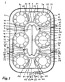
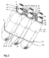
- FIG. 1 shows a plan view of a first embodiment of a handle 1 for six bottles 100, which in FIG. 2 are shown.
- the carrying handle 1 has six receiving elements 2a to 2f for receiving the bottle heads 102. Furthermore, the carrying handle has a gripping element 3, which extends between the receiving elements 2a to 2f. On the outside, the receiving elements are surrounded by a ring element 4. Between the individual receiving elements 2a to 2f 4 stiffening webs 5, 6, 7, 8, 9, 10 are provided with an edge approximately parallel to the ring member.
- the stiffening webs 5 to 9 have an approximately parallel to the ring member extending edge and extending with flat curved portions 50, 51, 60, 61, 70, 71, 80, 81, 90, 91 between the respective adjacent receiving elements.
- the stiffening web 10 is formed bent between the two receiving elements 2a and 2f.
- an identification flag 11 as an embodiment of an identification element for characterizing the later packaging unit of carrying handle and bottles is disposed on the ring member 4 and also extends into the space between the two receiving members 2a and 2f.
- an identification band or another form of identification element can be provided which is or is connected in a suitable manner to the carrying handle, in particular ring element.
- the identification flag 11 is arranged on a portion 40 of the ring element, which is connected via two torsion points 41, 42 to the rest of the ring element 4. About the two torsion points, it is possible to bend out the portion 40 with the identification flag 11 from the plane of the handle. As a result, a slight hiring of Ken Vietnamesesfähnchens in the later position of the ring member is possible, which is separated from the rest of the handle and along the bottles with respect to this pushed down to keep the bottles together also in the lower area. The final position of the flag 11 may be better FIG. 2 be removed.
- the identification flag 11 is here at an angle of about 65 ° relative to the horizontal. In such a position, an easy detection of the contents of the identification flag, eg the data of the packaging unit, including price data, eg by a scanner cash register, is possible.
- the grip element 3 surrounding, further connecting webs 12, 13, 14, 15, 16, 17 are provided. All connecting webs have a curved shape, wherein the connecting webs 12 to 16 are supported by further planar stiffening sections 120, 121, 130, 131, 140, 141, 150, 151, 160, 161 relative to the receiving elements 2a to 2f. Only the connecting web 17, which is arranged in the region of the identification flag 11, has no further stiffening sections. In principle, however, this could also have further stiffening sections, which are omitted for reasons of space here.
- the grip element 3 has a straight in the plan view middle holding portion 30 which is secured via four torsion bars 31, 32, 33, 34 to the connecting webs 13, 14, 16, 17.
- the attachment takes place via respective torsion points 35, 36, 37, 38.
- the middle holding portion 30 of the handle member 3 has a slightly curved shape in the side view, which better the FIG. 2 can be removed. By this slightly curved shape of the middle holding portion centering when stacking several carrying handles on each other for storage in a simple manner possible.
- the individual receiving elements can be designed accordingly to facilitate stacking.
- the receiving elements 2a to 2f each have retaining tabs 20 which engage on the underside of a protruding portion on the bottle head, which in FIG. 2 you can see.
- the retaining tabs 20 protrude inward from a circumferential retaining ring 21 and are, as well FIG. 2 can be better taken out of the plane of the handle out slightly inclined.
- retaining tabs 20 also other holding devices may be provided, such as retaining lugs or webs.
- retaining lugs or webs instead of the respective nine retaining tabs, a different number of retaining tabs can be provided, in particular when providing a different shape for this.
- the shape can also be chosen here arbitrarily, in particular, an adaptation to the respective bottle neck shape or bottle head shape is possible here.
- the surrounding the carrying handle ring member 4 is what the top view in FIG. 1 can not be removed, formed in cross-section approximately V-shaped to have a sufficient support surface 43 when pushing down the ring member along the bottles.
- the ring element is not rectangular in cross-section or square, so that can be saved by the V-shape over such a square or rectangular cross-sectional shape material.
- the ring member 4 is further secured via web members 44, 45, 46 to the remainder of the carrying handle, namely the stiffening webs 6, 7, 9.
- a respective predetermined breaking point 47, 48, 49 is provided between the web elements 44 to 46 and the stiffening webs 6, 7, 9.
- the closure member 113 is inserted into the housing 112 and locked in the desired paragraph 111 with its front projection 114. Due to the latching an unintentional release is no longer possible here, so that the closure device ensures that the container or bottles 100 of the ring element 4 tightly enclosed.
- This may also be the perspective view in FIG. 3 be removed. Here, the latched position of the closure device is shown. According to the embodiment in FIG. 3 can the case on its top open, so that the proper locking within the housing is visible from the outside. Likewise, the housing 112 may be formed closed.
- corresponding devices may be provided in automatic placement machines or the device for applying the carrying handles to the containers, via slide elements or corresponding other devices in the region of the housing 112 and in the region of the closure part 113 attacks and move them against each other until a close concern of the ring member 4 is done around the bottles around.
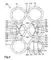
- FIG. 4 shows a non-inventive carrying handle 200, which is designed to accommodate six cans.
- six receiving elements 2a to 2f are formed, but provide shorter retaining tabs 245, since usually the upper edge is less pronounced in doses as a circumferential projection in beverage bottles.
- each stiffening webs 205 to 210 are also provided. In contrast to the stiffening webs 5 to 10, these are all formed uniformly, since a flag ID 211 is disposed within the receiving element 2d.
- the stiffening webs 205 to 210 are each formed as narrow, slightly curved webs between the individual receiving elements 2a to 2f.
- each further connecting webs 218, 219, 220, 221 are provided between the respective stiffening webs and connecting webs on the outside and inside of the carrying handle. They are wider than the stiffening and connecting webs, so that over this a stiffening of the entire handle is possible.
- the two receiving elements 2c and 2f are also connected via a further connecting web 222 connected together to stiffen the middle portion of the handle.
- the identification flag 211 is arranged via telescopic webs 240 to 243 within the receiving element 2d. Also, the telescopic webs 240 are serpentine curved back and forth, so that pushing out of the identification flag 11 from the plane of
Landscapes
- Engineering & Computer Science (AREA)
- Mechanical Engineering (AREA)
- Details Of Rigid Or Semi-Rigid Containers (AREA)
Claims (8)
- Support avec poignée (1) pour plusieurs récipients (100) avec un élément de préhension (3) et des éléments de réception (2a, 2b, 2c, 2d, 2e, 2f) pour la réception des récipients (100), pour lequel l'élément de préhension (3) présente une section de retenue (30) médiane droite dans la vue de dessus, s'étend entre les éléments de réception et est disposé parallèlement au plan du support avec poignée (1) tout en étant relevable de manière télescopique sur au moins deux endroits (35, 36, 37, 38) sur le support avec poignée (1),
caractérisé en ce que l'élément de préhension (3) se trouve à l'état non utilisé dans le plan du support avec poignée, en ce que les au moins deux endroits sont réalisés comme des endroits de torsion (35, 36, 37, 38) sur le support avec poignée (1) et la section de retenue (30) est fixée par des nervures de torsion (31, 32, 33, 34) sur des nervures de liaison (13, 14, 16, 17) entre des éléments de réception individuels (2a, 2b, 2c, 2d, 2e, 2f) au-dessus des endroits de torsion (35, 36, 37, 38), les nervures de torsion (31, 32, 33, 34) sortant par rotation de ce plan lors du relevage de manière télescopique de l'élément de préhension (3) hors du plan du support avec poignée (1) pour le relevage parallèle de la section de retenue par rapport au plan du support avec poignée (1). - Support avec poignée (1) selon la revendication 1, caractérisé en ce que les éléments de réception (2a, 2b, 2c, 2d, 2e, 2f), en particulier deux, quatre ou six éléments de réception sont reliés entre eux par des nervures de renforcement (5, 6, 7, 8, 9, 10) disposées côté extérieur par rapport au support avec poignée (1).
- Support avec poignée (1) selon l'une quelconque des revendications précédentes, caractérisé en ce que l'élément de préhension (3) présente au moins une section légèrement bombée pour le centrage lors de l'empilage de supports avec poignée.
- Support avec poignée (1) selon l'une quelconque des revendications précédentes, caractérisé en ce qu'au moins un élément annulaire (4) est fixé de manière amovible sur le support avec poignée (1) pour entourer les récipients (100) côté extérieur.
- Support avec poignée (1) selon la revendication 4, caractérisé en ce que l'élément annulaire (4) est pourvu d'au moins un dispositif de fermeture (110) pour la fixation sur les récipients (100), en particulier présente une section avec des ardillons accrochables les uns dans les autres ou le dispositif de fermeture (110) comporte au moins un élément pourvu d'ardillons et au moins un élément antagoniste coagissant avec celui-ci et/ou contient un dispositif d'encliquetage, en particulier présente une partie de boîtier (112) pourvue d'épaulements (111, 116) et une partie de fermeture (113) pourvue d'au moins une saillie (114, 115) côté extérieur, insérable dedans et/ou un dispositif de fermeture en chapelet avec des éléments enfilés, en particulier des éléments coniques, est prévu.
- Support avec poignée (1) selon la revendication 4 ou 5, caractérisé en ce que l'élément annulaire (4) présente une surface d'appui supérieure (43), dont la section transversale en particulier est en forme de V, pour la génération d'une surface d'appui pour la saisie lors du repoussement des parois de récipient.
- Support avec poignée (1) selon l'une quelconque des revendications 4 à 6, caractérisé en ce que l'élément annulaire (4) est relié de manière amovible par des éléments de nervure (44, 45, 46) à l'au moins un élément de réception (2a, 2b, 2c, 2d, 2e, 2f) et/ou aux nervures de renforcement (5, 6, 7, 8, 9, 10), en particulier un point destiné à la rupture (47, 48, 49) est prévu entre l'élément annulaire (4) et les éléments de nervure (44, 45, 46) et/ou un point destiné à la rupture est prévu entre les éléments de nervure (44, 45, 46) et l'au moins un élément de réception (2a, 2b, 2c, 2d, 2e, 2f) et/ou les nervures de renforcement (5, 6, 7, 8, 9, 10).
- Unité d'emballage composée d'un support avec poignée (1) selon l'une quelconque des revendications 1 à 7, et d'au moins deux récipients (100), caractérisée en ce que les récipients (100) sont entourés d'un élément annulaire (4), l'élément annulaire (4) étant pourvu d'au moins un dispositif de fermeture (110) pour la fixation sur les récipients (100).
Applications Claiming Priority (1)
| Application Number | Priority Date | Filing Date | Title |
|---|---|---|---|
| DE200710034870 DE102007034870A1 (de) | 2007-07-24 | 2007-07-24 | Tragegriff |
Publications (2)
| Publication Number | Publication Date |
|---|---|
| EP2028126A1 EP2028126A1 (fr) | 2009-02-25 |
| EP2028126B1 true EP2028126B1 (fr) | 2013-05-01 |
Family
ID=39760929
Family Applications (1)
| Application Number | Title | Priority Date | Filing Date |
|---|---|---|---|
| EP20080013311 Not-in-force EP2028126B1 (fr) | 2007-07-24 | 2008-07-24 | Support avec poignée |
Country Status (2)
| Country | Link |
|---|---|
| EP (1) | EP2028126B1 (fr) |
| DE (1) | DE102007034870A1 (fr) |
Families Citing this family (7)
| Publication number | Priority date | Publication date | Assignee | Title |
|---|---|---|---|---|
| GB0920396D0 (en) | 2009-11-23 | 2010-01-06 | Dijofi Ltd | A plastics container carrier |
| DE102011102683A1 (de) * | 2011-05-20 | 2012-11-22 | Khs Gmbh | Gebinde, Verfahren zum Herstellen von Gebinden sowie Vorrichtung zur Handhabung, Förderung, Verpackung und/oder Palettierung von Artikeln |
| WO2013004339A1 (fr) * | 2011-07-05 | 2013-01-10 | Khs Gmbh | Emballage multiple et procédé de réalisation d'un tel emballage multiple |
| GB2511622B (en) | 2013-01-22 | 2016-07-13 | Loadhog Ltd | Load capping arrangement |
| GB201317547D0 (en) * | 2013-10-03 | 2013-11-20 | P4Ck Ltd | Drinks Carrier |
| EP4417536A3 (fr) * | 2016-05-02 | 2025-04-16 | WestRock Packaging Systems, LLC | Ébauche pour former un support d'article |
| US11001428B2 (en) | 2017-07-14 | 2021-05-11 | Oregon Precision Industries, Inc. | Container carrier with flexible raised handle |
Family Cites Families (30)
| Publication number | Priority date | Publication date | Assignee | Title |
|---|---|---|---|---|
| US3084792A (en) * | 1960-09-23 | 1963-04-09 | Illinois Tool Works | Container carrier |
| DE1138194B (de) | 1960-10-19 | 1962-10-18 | Snap Pac Corp | Trage- und Haltevorrichtung fuer Behaelter |
| CA933889A (en) | 1970-04-30 | 1973-09-18 | Owens-Illinois | Container package |
| US3727754A (en) * | 1971-06-16 | 1973-04-17 | Illinois Tool Works | Container carrier |
| DE2144334A1 (de) | 1971-09-03 | 1973-03-08 | Walter Heubl | Flaschentraeger |
| US3946862A (en) | 1974-07-16 | 1976-03-30 | Illinois Tool Works Inc. | Container package |
| US4545480A (en) * | 1983-10-17 | 1985-10-08 | Illinois Tool Works Inc. | Bottle multi-package and multi-packaging device |
| DE8915740U1 (de) | 1989-06-02 | 1991-04-04 | Grafenwald Kunststoff GmbH & Co Verarbeitungs und Vertriebs KG, 5508 Hermeskeil | Gebinde bestehend aus Behältern und Tragrahmen |
| US5306060A (en) | 1992-07-06 | 1994-04-26 | Oregon Precision Industries, Inc. | Carrier strap for bottles or jugs |
| GB9307372D0 (en) | 1993-04-08 | 1993-06-02 | Mouldamatic Limited | Carrier for bottles and like containers |
| US5735562A (en) | 1997-02-18 | 1998-04-07 | Oregon Precision Industries, Inc. | Multi-container carrier |
| IT243928Y1 (it) | 1998-04-10 | 2002-03-06 | Affaba & Ferrari S N C | Dispositivo per il trasporto di bottiglie o contenitori similari |
| US6129397A (en) | 1998-07-15 | 2000-10-10 | Oregon Precision Industries | Six pack carrier |
| US6145656A (en) * | 1998-12-24 | 2000-11-14 | Illinois Tool Works Inc. | Film multipackage |
| US6536820B1 (en) * | 2000-11-14 | 2003-03-25 | Flexible Products Co. | Handle assembly for bulk fluid containers |
| US6394517B1 (en) | 2001-04-11 | 2002-05-28 | Oregon Precision Industries | Single bottle carrier |
| US6715810B2 (en) | 2002-09-09 | 2004-04-06 | Oregon Precision Industries, Inc. | Three bottle carrier |
| EP1597165A2 (fr) | 2003-02-26 | 2005-11-23 | Schoeller Wavin Systems Services GmbH | Support pour recipients, en particulier des bouteilles |
| US20040256250A1 (en) | 2003-06-23 | 2004-12-23 | Borg Zakary J. | Balanced multiple container carrier |
| US7108128B2 (en) | 2003-06-23 | 2006-09-19 | Oregon Precision Industries, Inc. | Balanced multiple container carrier |
| DE20311628U1 (de) | 2003-07-29 | 2003-09-25 | Guzik, Werner, 92224 Amberg | Halter für Flaschen |
| US6789828B1 (en) | 2003-08-04 | 2004-09-14 | Oregon Precision Industries, Inc. | Stabilizing two-bottle carrier |
| DE102004019437A1 (de) | 2004-04-19 | 2005-11-03 | Markus E.Kfm. Wulf | Tragvorrichtung für wenigstens ein Behältnis, insbesondere eine Flasche |
| DE112004002843T5 (de) | 2004-05-13 | 2007-05-10 | Roberts Polypro Inc. | Behälterträger |
| DE202005005970U1 (de) | 2005-04-14 | 2005-07-21 | Seifert, Gregor | Flaschenbündler für PET-Pfandflaschen |
| US7387200B2 (en) | 2005-05-16 | 2008-06-17 | Oregon Precision Industries, Inc. | Tandem harness for tub-like containers |
| DE202005014112U1 (de) | 2005-08-01 | 2005-12-29 | Terramark Markencreation Gmbh | Tragegriff |
| US7147100B1 (en) | 2005-08-09 | 2006-12-12 | Oregon Precision Industries, Inc. | Multiple-bottle securement and carrying device |
| US7377382B2 (en) | 2005-08-19 | 2008-05-27 | Oregon Precision Industries, Inc. | Multiple container carrier |
| DE202005016091U1 (de) | 2005-10-13 | 2005-12-08 | Schoeller Arca Systems Services Gmbh | Träger für Flaschen u.dgl. Behälter |
-
2007
- 2007-07-24 DE DE200710034870 patent/DE102007034870A1/de not_active Withdrawn
-
2008
- 2008-07-24 EP EP20080013311 patent/EP2028126B1/fr not_active Not-in-force
Also Published As
| Publication number | Publication date |
|---|---|
| EP2028126A1 (fr) | 2009-02-25 |
| DE102007034870A1 (de) | 2009-01-29 |
Similar Documents
| Publication | Publication Date | Title |
|---|---|---|
| EP2028126B1 (fr) | Support avec poignée | |
| DE2635523A1 (de) | Packung und tragevorrichtung fuer mehrere flaschen oder dergleichen behaelter | |
| DE60011410T2 (de) | Behälterhandgriff und zugehörige verfahren | |
| DE2226511A1 (de) | Träger vorrichtung für Mehrfach-Behälterträger | |
| DE1457489A1 (de) | Tragpaket | |
| EP2334567B1 (fr) | Poignée de manutention pour conteneur | |
| DE1953575A1 (de) | Behaelterpackung | |
| DE102011102571A1 (de) | Interdentalreiniger-Set und Verkaufseinheit für dieses | |
| DE69614934T2 (de) | Behälterverpackung | |
| DE202012103324U1 (de) | Gebindeschablone zum Zusammenfügen von Verpackungseinheiten | |
| DE202004017954U1 (de) | Trage für Bügelverschluss-Flaschen | |
| DE69503494T2 (de) | Auf und um einen behälter aufzubringende verpackung und werkzeug und verfahren dazu | |
| DE69600342T2 (de) | Träger sowie Packung, die diesen enthält | |
| DE69004257T2 (de) | Zusätzliche griffeinrichtung an einem handgriff. | |
| DE202019106962U1 (de) | Zuschnitt für eine Aufnahmevorrichtung für Getränkeverpackungen | |
| DE69513242T2 (de) | Behälterträger und aus diesem geformte Verpackung | |
| EP2383189B1 (fr) | Unité de transport/présentation avec support de transport/présentation pour récipients, de préférence récipients à boissons | |
| EP2711308B1 (fr) | Emballage d'entourage pour conteneurs | |
| DE102012204663A1 (de) | Tray und Traysystem zum Transport von Behältergebinden | |
| WO2008006555A1 (fr) | Dispositif porteur pour bouteilles (en matière plastique) | |
| DE102019201406A1 (de) | Flaschenträger aus zellulosehaltigem Flachmaterial | |
| DE112004002843T5 (de) | Behälterträger | |
| EP1353856A1 (fr) | Dispositif porte-bouteilles a pose mecanique | |
| EP0400400A2 (fr) | Ensemble d'emballage constitué par des réceptacles et un châssis de support | |
| DE102019123824A1 (de) | Verbindungsmittel |
Legal Events
| Date | Code | Title | Description |
|---|---|---|---|
| PUAI | Public reference made under article 153(3) epc to a published international application that has entered the european phase |
Free format text: ORIGINAL CODE: 0009012 |
|
| AK | Designated contracting states |
Kind code of ref document: A1 Designated state(s): AT BE BG CH CY CZ DE DK EE ES FI FR GB GR HR HU IE IS IT LI LT LU LV MC MT NL NO PL PT RO SE SI SK TR |
|
| AX | Request for extension of the european patent |
Extension state: AL BA MK RS |
|
| AKX | Designation fees paid |
Designated state(s): AT BE BG CH CY CZ DE DK EE ES FI FR GB GR HR HU IE IS IT LI LT LU LV MC MT NL NO PL PT RO SE SI SK TR |
|
| 17P | Request for examination filed |
Effective date: 20090825 |
|
| 17Q | First examination report despatched |
Effective date: 20091105 |
|
| GRAP | Despatch of communication of intention to grant a patent |
Free format text: ORIGINAL CODE: EPIDOSNIGR1 |
|
| GRAS | Grant fee paid |
Free format text: ORIGINAL CODE: EPIDOSNIGR3 |
|
| GRAA | (expected) grant |
Free format text: ORIGINAL CODE: 0009210 |
|
| AK | Designated contracting states |
Kind code of ref document: B1 Designated state(s): AT BE BG CH CY CZ DE DK EE ES FI FR GB GR HR HU IE IS IT LI LT LU LV MC MT NL NO PL PT RO SE SI SK TR |
|
| REG | Reference to a national code |
Ref country code: GB Ref legal event code: FG4D Free format text: NOT ENGLISH |
|
| REG | Reference to a national code |
Ref country code: CH Ref legal event code: EP Ref country code: AT Ref legal event code: REF Ref document number: 609797 Country of ref document: AT Kind code of ref document: T Effective date: 20130515 |
|
| REG | Reference to a national code |
Ref country code: IE Ref legal event code: FG4D Free format text: LANGUAGE OF EP DOCUMENT: GERMAN |
|
| REG | Reference to a national code |
Ref country code: DE Ref legal event code: R096 Ref document number: 502008009821 Country of ref document: DE Effective date: 20130704 |
|
| REG | Reference to a national code |
Ref country code: NL Ref legal event code: VDEP Effective date: 20130501 |
|
| REG | Reference to a national code |
Ref country code: LT Ref legal event code: MG4D |
|
| PG25 | Lapsed in a contracting state [announced via postgrant information from national office to epo] |
Ref country code: LT Free format text: LAPSE BECAUSE OF FAILURE TO SUBMIT A TRANSLATION OF THE DESCRIPTION OR TO PAY THE FEE WITHIN THE PRESCRIBED TIME-LIMIT Effective date: 20130501 Ref country code: SI Free format text: LAPSE BECAUSE OF FAILURE TO SUBMIT A TRANSLATION OF THE DESCRIPTION OR TO PAY THE FEE WITHIN THE PRESCRIBED TIME-LIMIT Effective date: 20130501 Ref country code: NO Free format text: LAPSE BECAUSE OF FAILURE TO SUBMIT A TRANSLATION OF THE DESCRIPTION OR TO PAY THE FEE WITHIN THE PRESCRIBED TIME-LIMIT Effective date: 20130801 Ref country code: GR Free format text: LAPSE BECAUSE OF FAILURE TO SUBMIT A TRANSLATION OF THE DESCRIPTION OR TO PAY THE FEE WITHIN THE PRESCRIBED TIME-LIMIT Effective date: 20130802 Ref country code: SE Free format text: LAPSE BECAUSE OF FAILURE TO SUBMIT A TRANSLATION OF THE DESCRIPTION OR TO PAY THE FEE WITHIN THE PRESCRIBED TIME-LIMIT Effective date: 20130501 Ref country code: PT Free format text: LAPSE BECAUSE OF FAILURE TO SUBMIT A TRANSLATION OF THE DESCRIPTION OR TO PAY THE FEE WITHIN THE PRESCRIBED TIME-LIMIT Effective date: 20130902 Ref country code: ES Free format text: LAPSE BECAUSE OF FAILURE TO SUBMIT A TRANSLATION OF THE DESCRIPTION OR TO PAY THE FEE WITHIN THE PRESCRIBED TIME-LIMIT Effective date: 20130812 Ref country code: FI Free format text: LAPSE BECAUSE OF FAILURE TO SUBMIT A TRANSLATION OF THE DESCRIPTION OR TO PAY THE FEE WITHIN THE PRESCRIBED TIME-LIMIT Effective date: 20130501 Ref country code: IS Free format text: LAPSE BECAUSE OF FAILURE TO SUBMIT A TRANSLATION OF THE DESCRIPTION OR TO PAY THE FEE WITHIN THE PRESCRIBED TIME-LIMIT Effective date: 20130901 |
|
| PG25 | Lapsed in a contracting state [announced via postgrant information from national office to epo] |
Ref country code: BG Free format text: LAPSE BECAUSE OF FAILURE TO SUBMIT A TRANSLATION OF THE DESCRIPTION OR TO PAY THE FEE WITHIN THE PRESCRIBED TIME-LIMIT Effective date: 20130801 Ref country code: CY Free format text: LAPSE BECAUSE OF FAILURE TO SUBMIT A TRANSLATION OF THE DESCRIPTION OR TO PAY THE FEE WITHIN THE PRESCRIBED TIME-LIMIT Effective date: 20130501 Ref country code: PL Free format text: LAPSE BECAUSE OF FAILURE TO SUBMIT A TRANSLATION OF THE DESCRIPTION OR TO PAY THE FEE WITHIN THE PRESCRIBED TIME-LIMIT Effective date: 20130501 Ref country code: HR Free format text: LAPSE BECAUSE OF FAILURE TO SUBMIT A TRANSLATION OF THE DESCRIPTION OR TO PAY THE FEE WITHIN THE PRESCRIBED TIME-LIMIT Effective date: 20130501 |
|
| PG25 | Lapsed in a contracting state [announced via postgrant information from national office to epo] |
Ref country code: LV Free format text: LAPSE BECAUSE OF FAILURE TO SUBMIT A TRANSLATION OF THE DESCRIPTION OR TO PAY THE FEE WITHIN THE PRESCRIBED TIME-LIMIT Effective date: 20130501 |
|
| BERE | Be: lapsed |
Owner name: RICHARDSON, MIRCO I. Effective date: 20130731 Owner name: WAFFENSCHMIDT, DIRK Effective date: 20130731 Owner name: ROTTGER, KLAUS Effective date: 20130731 |
|
| PG25 | Lapsed in a contracting state [announced via postgrant information from national office to epo] |
Ref country code: SK Free format text: LAPSE BECAUSE OF FAILURE TO SUBMIT A TRANSLATION OF THE DESCRIPTION OR TO PAY THE FEE WITHIN THE PRESCRIBED TIME-LIMIT Effective date: 20130501 Ref country code: DK Free format text: LAPSE BECAUSE OF FAILURE TO SUBMIT A TRANSLATION OF THE DESCRIPTION OR TO PAY THE FEE WITHIN THE PRESCRIBED TIME-LIMIT Effective date: 20130501 Ref country code: EE Free format text: LAPSE BECAUSE OF FAILURE TO SUBMIT A TRANSLATION OF THE DESCRIPTION OR TO PAY THE FEE WITHIN THE PRESCRIBED TIME-LIMIT Effective date: 20130501 Ref country code: CZ Free format text: LAPSE BECAUSE OF FAILURE TO SUBMIT A TRANSLATION OF THE DESCRIPTION OR TO PAY THE FEE WITHIN THE PRESCRIBED TIME-LIMIT Effective date: 20130501 |
|
| PG25 | Lapsed in a contracting state [announced via postgrant information from national office to epo] |
Ref country code: NL Free format text: LAPSE BECAUSE OF FAILURE TO SUBMIT A TRANSLATION OF THE DESCRIPTION OR TO PAY THE FEE WITHIN THE PRESCRIBED TIME-LIMIT Effective date: 20130501 Ref country code: IT Free format text: LAPSE BECAUSE OF FAILURE TO SUBMIT A TRANSLATION OF THE DESCRIPTION OR TO PAY THE FEE WITHIN THE PRESCRIBED TIME-LIMIT Effective date: 20130501 Ref country code: RO Free format text: LAPSE BECAUSE OF FAILURE TO SUBMIT A TRANSLATION OF THE DESCRIPTION OR TO PAY THE FEE WITHIN THE PRESCRIBED TIME-LIMIT Effective date: 20130501 Ref country code: MC Free format text: LAPSE BECAUSE OF FAILURE TO SUBMIT A TRANSLATION OF THE DESCRIPTION OR TO PAY THE FEE WITHIN THE PRESCRIBED TIME-LIMIT Effective date: 20130501 |
|
| REG | Reference to a national code |
Ref country code: CH Ref legal event code: PL |
|
| PLBE | No opposition filed within time limit |
Free format text: ORIGINAL CODE: 0009261 |
|
| STAA | Information on the status of an ep patent application or granted ep patent |
Free format text: STATUS: NO OPPOSITION FILED WITHIN TIME LIMIT |
|
| 26N | No opposition filed |
Effective date: 20140204 |
|
| GBPC | Gb: european patent ceased through non-payment of renewal fee |
Effective date: 20130801 |
|
| REG | Reference to a national code |
Ref country code: IE Ref legal event code: MM4A |
|
| REG | Reference to a national code |
Ref country code: DE Ref legal event code: R119 Ref document number: 502008009821 Country of ref document: DE Effective date: 20140201 |
|
| REG | Reference to a national code |
Ref country code: FR Ref legal event code: ST Effective date: 20140331 |
|
| PG25 | Lapsed in a contracting state [announced via postgrant information from national office to epo] |
Ref country code: LI Free format text: LAPSE BECAUSE OF NON-PAYMENT OF DUE FEES Effective date: 20130731 Ref country code: DE Free format text: LAPSE BECAUSE OF NON-PAYMENT OF DUE FEES Effective date: 20140201 Ref country code: BE Free format text: LAPSE BECAUSE OF NON-PAYMENT OF DUE FEES Effective date: 20130731 Ref country code: CH Free format text: LAPSE BECAUSE OF NON-PAYMENT OF DUE FEES Effective date: 20130731 |
|
| PG25 | Lapsed in a contracting state [announced via postgrant information from national office to epo] |
Ref country code: FR Free format text: LAPSE BECAUSE OF NON-PAYMENT OF DUE FEES Effective date: 20130731 |
|
| PG25 | Lapsed in a contracting state [announced via postgrant information from national office to epo] |
Ref country code: GB Free format text: LAPSE BECAUSE OF NON-PAYMENT OF DUE FEES Effective date: 20130801 Ref country code: IE Free format text: LAPSE BECAUSE OF NON-PAYMENT OF DUE FEES Effective date: 20130724 |
|
| REG | Reference to a national code |
Ref country code: AT Ref legal event code: MM01 Ref document number: 609797 Country of ref document: AT Kind code of ref document: T Effective date: 20130724 |
|
| PG25 | Lapsed in a contracting state [announced via postgrant information from national office to epo] |
Ref country code: AT Free format text: LAPSE BECAUSE OF NON-PAYMENT OF DUE FEES Effective date: 20130724 |
|
| PG25 | Lapsed in a contracting state [announced via postgrant information from national office to epo] |
Ref country code: TR Free format text: LAPSE BECAUSE OF FAILURE TO SUBMIT A TRANSLATION OF THE DESCRIPTION OR TO PAY THE FEE WITHIN THE PRESCRIBED TIME-LIMIT Effective date: 20130501 Ref country code: MT Free format text: LAPSE BECAUSE OF FAILURE TO SUBMIT A TRANSLATION OF THE DESCRIPTION OR TO PAY THE FEE WITHIN THE PRESCRIBED TIME-LIMIT Effective date: 20130501 |
|
| PG25 | Lapsed in a contracting state [announced via postgrant information from national office to epo] |
Ref country code: LU Free format text: LAPSE BECAUSE OF NON-PAYMENT OF DUE FEES Effective date: 20130724 Ref country code: HU Free format text: LAPSE BECAUSE OF FAILURE TO SUBMIT A TRANSLATION OF THE DESCRIPTION OR TO PAY THE FEE WITHIN THE PRESCRIBED TIME-LIMIT; INVALID AB INITIO Effective date: 20080724 |