EP2025837A1 - Drehhandhabe für einen Verschluss eines Flügels eines Fensters oder dergleichen sowie Verfahren zur Betätigung des Verschlusses - Google Patents
Drehhandhabe für einen Verschluss eines Flügels eines Fensters oder dergleichen sowie Verfahren zur Betätigung des Verschlusses Download PDFInfo
- Publication number
- EP2025837A1 EP2025837A1 EP07016030A EP07016030A EP2025837A1 EP 2025837 A1 EP2025837 A1 EP 2025837A1 EP 07016030 A EP07016030 A EP 07016030A EP 07016030 A EP07016030 A EP 07016030A EP 2025837 A1 EP2025837 A1 EP 2025837A1
- Authority
- EP
- European Patent Office
- Prior art keywords
- rotary handle
- handle according
- rotary
- handle
- operating
- Prior art date
- Legal status (The legal status is an assumption and is not a legal conclusion. Google has not performed a legal analysis and makes no representation as to the accuracy of the status listed.)
- Granted
Links
Images








Classifications
-
- E—FIXED CONSTRUCTIONS
- E05—LOCKS; KEYS; WINDOW OR DOOR FITTINGS; SAFES
- E05B—LOCKS; ACCESSORIES THEREFOR; HANDCUFFS
- E05B5/00—Handles completely let into the surface of the wing
- E05B5/003—Pop-out handles, e.g. sliding outwardly before rotation
-
- E—FIXED CONSTRUCTIONS
- E05—LOCKS; KEYS; WINDOW OR DOOR FITTINGS; SAFES
- E05B—LOCKS; ACCESSORIES THEREFOR; HANDCUFFS
- E05B1/00—Knobs or handles for wings; Knobs, handles, or press buttons for locks or latches on wings
- E05B1/0092—Moving otherwise than only rectilinearly or only rotatively
-
- E—FIXED CONSTRUCTIONS
- E05—LOCKS; KEYS; WINDOW OR DOOR FITTINGS; SAFES
- E05B—LOCKS; ACCESSORIES THEREFOR; HANDCUFFS
- E05B13/00—Devices preventing the key or the handle or both from being used
- E05B13/10—Devices preventing the key or the handle or both from being used formed by a lock arranged in the handle
- E05B13/101—Devices preventing the key or the handle or both from being used formed by a lock arranged in the handle for disconnecting the handle
-
- E—FIXED CONSTRUCTIONS
- E05—LOCKS; KEYS; WINDOW OR DOOR FITTINGS; SAFES
- E05B—LOCKS; ACCESSORIES THEREFOR; HANDCUFFS
- E05B15/00—Other details of locks; Parts for engagement by bolts of fastening devices
- E05B15/0053—Other details of locks; Parts for engagement by bolts of fastening devices means providing a stable, i.e. indexed, position of lock parts
- E05B15/006—Spring-biased ball or roller entering a notch
-
- E—FIXED CONSTRUCTIONS
- E05—LOCKS; KEYS; WINDOW OR DOOR FITTINGS; SAFES
- E05B—LOCKS; ACCESSORIES THEREFOR; HANDCUFFS
- E05B65/00—Locks or fastenings for special use
- E05B65/08—Locks or fastenings for special use for sliding wings
-
- E—FIXED CONSTRUCTIONS
- E05—LOCKS; KEYS; WINDOW OR DOOR FITTINGS; SAFES
- E05C—BOLTS OR FASTENING DEVICES FOR WINGS, SPECIALLY FOR DOORS OR WINDOWS
- E05C7/00—Fastening devices specially adapted for two wings
- E05C2007/007—Fastening devices specially adapted for two wings for a double-wing sliding door or window, i.e. where both wings are slidable
-
- Y—GENERAL TAGGING OF NEW TECHNOLOGICAL DEVELOPMENTS; GENERAL TAGGING OF CROSS-SECTIONAL TECHNOLOGIES SPANNING OVER SEVERAL SECTIONS OF THE IPC; TECHNICAL SUBJECTS COVERED BY FORMER USPC CROSS-REFERENCE ART COLLECTIONS [XRACs] AND DIGESTS
- Y10—TECHNICAL SUBJECTS COVERED BY FORMER USPC
- Y10T—TECHNICAL SUBJECTS COVERED BY FORMER US CLASSIFICATION
- Y10T292/00—Closure fasteners
- Y10T292/08—Bolts
- Y10T292/1043—Swinging
- Y10T292/1075—Operating means
- Y10T292/1083—Rigid
-
- Y—GENERAL TAGGING OF NEW TECHNOLOGICAL DEVELOPMENTS; GENERAL TAGGING OF CROSS-SECTIONAL TECHNOLOGIES SPANNING OVER SEVERAL SECTIONS OF THE IPC; TECHNICAL SUBJECTS COVERED BY FORMER USPC CROSS-REFERENCE ART COLLECTIONS [XRACs] AND DIGESTS
- Y10—TECHNICAL SUBJECTS COVERED BY FORMER USPC
- Y10T—TECHNICAL SUBJECTS COVERED BY FORMER US CLASSIFICATION
- Y10T74/00—Machine element or mechanism
- Y10T74/20—Control lever and linkage systems
- Y10T74/20576—Elements
- Y10T74/20732—Handles
- Y10T74/20744—Hand crank
Definitions
- the invention relates to a rotary handle for a closure of a wing of a window, a door or the like, in particular a sliding leaf, with an operating handle which is at least partially recessed in its rest position in terms of height in the wing and from the rest position to a working position as a folding handle can be swung out in outstanding position, wherein it is rotatable about a rotation axis in the working position.
- a rotary handle of the type mentioned is from the DE 102 04 744 A1 known. It has an actuating handle, which sunk in its rest position rests in the associated wing and can be folded out of this rest position into a working position, so that at least a portion of the operating handle protrudes from the plane of the wing. Subsequently, the operating handle can be rotated by operating the shutter. By sinking the operating handle, an adjacent wing can be moved in parallel at a short distance on the first-mentioned wing, without causing a collision with the rotary handle. The prerequisite is that the rotary handle is first returned under actuation of the shutter in the output rotational position and then folded in lowered position.
- the invention has for its object to provide a rotary handle of the type mentioned, which is more versatile and even less annoying.
- an operating element with which a coupling or uncoupling position to a mitFEbaren with the actuating handle in the coupling position and not unwindable in uncoupling control occurs. Due to this configuration, the operating handle in any desired rotational position with the control can couple or uncouple, so that it can always be returned to its rest position, ie recessed position, regardless of which caused by the rotational position operating position is present at the control. It can therefore be spent, for example, in the locked position in its rest position.
- the actuating handle has the operating element. Since the operating element is located on the actuating handle, a particularly simple, preferably one-hand operation is possible since, when the operating handle is gripped, an actuation of the operating element-if desired-can additionally take place.
- the operating element is a sliding element.
- the actuating handle is enclosed by the user's hand, whereby he can press the sliding element with his thumb.
- the actuating handle and / or the operating element is a manually operable component or are manually operable components.
- the rotary handle is thus actuated manually by the user. Should a motor actuation take place, the rotary handle can also be driven by a motor in relation to its actuating handle and / or the operating element.
- a further development of the invention provides that the operating element cooperates with a pivoting element which is in a coupling position with the control element in engagement and in a disengaged position with the control element out of engagement.
- the control element can thus influence the pivoting element in its position, such that a coupling between the actuating handle and the control is made, so that upon rotation of the actuating handle, a corresponding rotational movement of the control takes place, or that by uncoupling, ie an operation of the control element in that the pivoting element is disengaged from the control element, whereby a rotary movement of the actuating grip is possible without the control element being taken along. It therefore remains in its respective position.
- the operating handle can be, for example From the working position lead back to the rest position and thus has a sunken, not disturbing position.
- a development of the invention provides that the pivoting element is mounted pivotably about a pivot axis.
- the actuating handle is preferably also hinged around this pivot axis as a folding handle. Accordingly, the pivot axis forms a common axis for the pivot member and the operating handle.
- the operating element is coupled to a slider or has the slider, wherein the slider cooperates with the pivoting element.
- a displacement of the slider causes the pivot member is brought into its coupling position or uncoupling position.
- the pivoting element rotates when the operating handle is rotated about its axis of rotation. If the pivoting element is not coupled to the control element, the actuating handle and the pivoting element are rotated without the control element rotating. If there is a coupling between the pivoting element and the control element, the control element is entrained when the operating handle is rotated via the pivoting element.
- the coupling or uncoupling position can be brought about independently of the rotational position of the actuating handle with the operating element. This leads - as already mentioned - to the independence of the positions of the operating handle and control, if the uncoupling is present. Is the Selected coupling position, so leads to a rotation of the operating handle to take the control.
- the control element preferably has a control bolt, in particular a polygonal bolt, preferably a square bolt. It serves for the rotationally fixed entrainment of a closure actuating element, for example a gear, the teeth of which mesh with recesses of drive rods.
- the control cooperates with a rotational locking position device. Due to the rotational locking positions, the control can be noticeably turned into certain positions, for example into a locking position and an unlocking position. These two positions are noticeable by the user due to the rotational locking device, but can be overcome by a corresponding, slightly increased effort.
- a development of the invention is characterized by a housing, in which the operating handle in the rest position is at least partially retractable with respect to its height.
- the housing is designed in particular as a built-in housing.
- the actuating handle is in the rest position completely or substantially sunk in the housing, in particular installation housing. If the actuating handle is in the working position, its longitudinal extent forms an acute angle with the longitudinal extension of the housing.
- control is mounted floating in the housing.
- control axially spring loaded by means of a spring in the housing stores.
- the spring acts between the control element and a rotatable part rotatably mounted in the housing.
- the spring acts on a ball bearing, which is supported on the rotary member or on the control.
- the bearing ball rests with a partial spherical surface in a bearing recess of the rotary member or the control.
- the operating handle is pivotally mounted on the rotary member.
- the invention relates to a method for actuating a closure of a wing of a window, a door or the like, in particular a sliding sash, by means of a rotary handle, in particular - as mentioned above - is formed.
- FIG. 1 shows the front view of a rotary handle 1, with a non-illustrated closure of a wing of a window, a door or the like, in particular a sliding leaf, can be actuated.
- the rotary handle 1 has a handle 2 designed as a folding handle 3.
- the rotary handle 1 has a housing 4, which is designed as a mounting housing 5.
- a front panel 6 has a gripping edge 7 such that a recessed installation of the rotary handle 1 in a corresponding recess of the sliding leaf is possible, with only the grip edge 7 is supported on the top of the sliding leaf.
- the folding handle 2 is located in the FIG. 1 in its rest position, in which its top 8 is aligned with the top 9 of the front panel 6.
- the rotary handle 1 is elongated and it is therefore also an elongated shape before the operating handle 3. However, this does not extend with its lower end portion 10 to the lower associated end 11 of the housing 4, so that an engagement recess 12 is formed.
- the user can therefore engage with a finger in the engaging recess 12 and the underside and / or the lower edge region of the actuating handle 3 apply to him in the folded position according to FIG. 6 to relocate.
- This folding position represents a working position.
- the operating handle 3 is an operating element 13, which can be preferably operated by the user with the thumb.
- the operating element is designed as a sliding element 14 and is located in the FIG. 1 in an ineffective engagement. This Ineingriff Basil will not be effective because the operating handle 3 is in rest position.
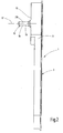
- FIG. 2 shows a side view of the installation housing 5, wherein the operating handle 3 is in rest position. From the back 15 of the mounting housing protrudes a control 16 out, which is rotatably mounted about a rotation axis 17.
- the control element 16 preferably has a control bolt 18, in particular a polygonal bolt 19, preferably a square bolt 20.
- FIG. 3 shows a rear view of the rotary handle 1.
- the housing 4 is closed by a rear wall 21 in its upper region.
- the rear wall 21 is held by four threaded screws 22.
- the formation of the control element 16 as a square bolt 20 is the FIG. 3 to be taken clearly.
- FIG. 4 shows an end view of the rotary handle. 1
- FIG. 5 shows - in longitudinal section view - the internal structure of the rotary handle 1.
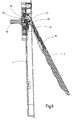
- the operating handle 3 is about a pivot axis 23 which is formed by a bearing pin 24, pivotable, the two pivot end positions (rest position and working position) from a comparison of Figures 5 and 6 evident.
- the bearing pin 24 is arranged on a torsion part 25, which is preferably rotatable about the rotation axis 17 by 360 °.
- a pivot member 26 is pivotally mounted. Interspersed for this the bearing pin 24 has a receiving bore 27 of the pivoting element.
- the pivot member 26 Spaced to the pivot axis 23, the pivot member 26 has a control surface 28 which is formed as an inclined surface 29.
- the operating element 13 designed as a sliding element 14 is coupled to a slide 31, wherein the slide 31 is longitudinally displaceable on the actuating handle 3 and preferably has a control surface 33 at one end 32, which is designed as an inclined surface 34.
- the slider 31 is biased by means of a spring 35, which is designed as a helical compression spring 36, in the direction of the operating element 13 (arrow 37).
- the helical compression spring 36 is supported both on the actuating handle 3, and on the slide 31. Trained as a sliding element 14 control element 13 is mounted in the direction of the double arrow 38 - as well as the slide 31 - on the operating handle 3 slidably.
- the control element 16 has the already mentioned square bolt 20, to which a cross-sectional larger circular cross-section 39 connects, which is rotatably mounted about the axis of rotation 17 in a bearing cup 40.
- the bearing cup 40 is located within the housing 4 in a rotationally fixed position. It has two diametrically opposite spring shafts 41. Further, the bearing cup 40 passes through the back 15 of the housing 4 with a tube extension 42.
- springs 43 are formed, which are formed as helical compression springs 44.
- the two helical compression springs 44 each act on a detent ball 45, wherein the two detent balls 45 - according to FIG.
- control element 16 Due to the action of the spring force of the helical compression spring 52, the control element 16 in the direction of the arrow 55 (FIG. FIG. 5 ). It is - depending on the operating condition - with its flange 47 on the bearing pot 40 and urges this also in the direction of the arrow 55 so that it is urged against the inside of the back 15 of the housing 4. It can be seen from all this that the control element 16 is mounted to a certain extent floating in the housing 4, so that any existing tolerances, positional errors and misalignment with respect to the coupling with the square bolt 20 can be compensated for the mentioned closure.
- the designed as a mounting housing 5 housing 4 can be fixed in the lowered position due to three mounting holes 56 by means of suitable mounting screws on said sliding leaf.
- “Countersink” means that the top of the front panel 6 is flush with or substantially flush with the corresponding surface of the sash.
- an inner bearing part 57 which consists of a first bearing part 58 and a second bearing part 59 and is screwed by means of four threaded screws 60 with the housing 4.
- the structure of the rotary handle 1 is in particular from the exploded view of FIG. 9 out.
- the rotary member 25 has bearing blocks 61, which are penetrated by the bearing pin 24.
- a friction ring 62 receives the edge of the torsion 25 and supports the torsion 25 in a receptacle 63 of the inner bearing part 15.
- One of the mounting holes 56 is formed in an insert 64, which is insertable into the housing 4.
- the slider 31 is held on the operating handle 3 by means of a back cover 65.
- the rocker-like pivot member 26 is associated with a spring 66 which, according to arrow 67 in FIG. 5 pivots the pivot member 26 in the clockwise direction about the pivot axis 23, whereby the control surfaces 28 and 33 collide.
- a spring 68 which is formed as a helical compression spring 69, acts on the rear side of the actuating handle 23 by corresponding support on an inner surface of the housing 4 such that the actuating handle 3 about the pivot axis 23 in the direction of its rest position FIG. 5 is urged.
- a clip-on screw head cover 70 By means of a clip-on screw head cover 70, the associated mounting hole 56 can be covered.
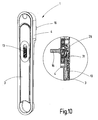
- FIG. 5 goes again in perspective plan view and partial sectional view of the FIG. 10 out.
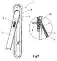
- the situation according to FIG. 6 also goes in perspective view and partial sectional view of the FIG. 11 out.
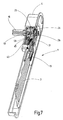
- the FIG. 7 illustrates the internal structure of the rotary handle 1 based on a partially cutaway perspective view of the rotary handle 1.
- the actuating handle 3 is in its rest position.
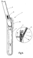
- FIG. 12 shows a rotational position of the operating handle 3 of the rotary handle 1, which from the situation according to FIG. 11 can be brought about.
- the user rotates - starting from the Situation of FIG. 11 -
- the actuating pin 3 about the axis of rotation 17.
- the pivot member 26 takes the control 16, so that by means of the square bolt 20, a closure of the wing can be operated.
- this allows the closure spend from its locking position in its unlocked position.
- it is - according to FIG.
- FIG. 14 It is also possible to make not only a 90 ° rotation of the operating handle 3 and the control element 16, but for example a 180 ° rotation. Also in the position of FIG. 14 can a decoupling of the operating handle 3 of the control element 16 by means of the operation of the operating element 13th be made.
- the operating element 13 is preferably actuated by means of the thumb of the user.
- the various angles of rotation are preferably characterized by slight latching effects of the latching balls 15, which can enter into correspondingly arranged latching recesses 46 of the flange 47 of the control element 16.
- the operating handle 3 from the position of FIG. 10 with actuated control element 13 first in the position of FIG. 11 spent, then - at a 90 ° twist - in the position according to FIG. 13 twisted, then brought about by actuation of the control element 13, the coupling position with the control element 13 and then taking the control 16 in the position according to FIG. 11 spent and then in the rest position according to FIG. 10 pivoted.
Landscapes
- Lock And Its Accessories (AREA)
- Window Of Vehicle (AREA)
- Power-Operated Mechanisms For Wings (AREA)
- Wing Frames And Configurations (AREA)
- Closing And Opening Devices For Wings, And Checks For Wings (AREA)
Abstract
Description
- Die Erfindung betrifft eine Drehhandhabe für einen Verschluss eines Flügels eines Fensters, einer Tür oder dergleichen, insbesondere eines Schiebeflügels, mit einem Betätigungsgriff, der in seiner Ruhelage mindestens teilweise hinsichtlich seiner Bauhöhe in dem Flügel versenkt anordenbar ist und aus der Ruhelage in eine Arbeitsstellung als Klappgriff in Herausraglage herausgeschwenkt werden kann, wobei er in der Arbeitsstellung um eine Drehachse verdrehbar ist.
- Eine Drehhandhabe der eingangs genannten Art ist aus der
DE 102 04 744 A1 bekannt. Sie weist einen Betätigungsgriff auf, der in seiner Ruhelage versenkt in dem zugehörigen Flügel ruht und aus dieser Ruhelage in eine Arbeitsstellung herausgeklappt werden kann, sodass zumindest ein Bereich des Betätigungsgriffs aus der Ebene des Flügels herausragt. Anschließend lässt sich der Betätigungsgriff unter Betätigung des Verschlusses verdrehen. Durch das Versenken des Betätigungsgriffes kann ein benachbarter Flügel in kurzer Entfernung parallel an dem erstgenannten Flügel vorbeibewegt werden, ohne dass es zu einer Kollision mit der Drehhandhabe kommt. Voraussetzung ist dabei, dass die Drehhandhabe zunächst unter Betätigung des Verschlusses in die Ausgangsdrehstellung zurückgeführt und dann in Versenkstellung geklappt wird. - Der Erfindung liegt die Aufgabe zugrunde, eine Drehhandhabe der eingangs genannten Art zu schaffen, die vielseitiger anwendbar und noch weniger störend ist.
- Diese Aufgabe wird erfindungsgemäß gelöst durch ein Bedienelement, mit dem eine Kupplungs- oder Entkupplungsstellung zu einem mit dem Betätigungsgriff in Kupplungsstellung mitdrehbaren und in Entkupplungsstellung nicht mitdrehbaren Steuerelement erfolgt. Aufgrund dieser Ausgestaltung lässt sich der Betätigungsgriff in jeder gewünschten Drehstellung mit dem Steuerelement kuppeln beziehungsweise entkuppeln, sodass er stets in seine Ruhelage, also versenkte Lage zurückgeführt werden kann, unabhängig davon, welche durch die Drehstellung bewirkte Betriebsstellung bei dem Steuerelement vorliegt. Er kann daher beispielsweise in Verriegelungsstellung in seine Ruhelage verbracht werden. Wurde der Flügel durch Herbeiführen der entsprechenden Drehstellung des Betätigungsgriffs entriegelt, liegt also als Betriebsstellung eine Entriegelungsstellung vor, so lässt sich der Betätigungsgriff durch Entkupplung von dem in der Entriegelungsstellung verbleibenden Steuerelement dennoch in seine Ruhelage, also in Versenkstellung verbringen, sodass auch in dieser Betriebsstellung der Betätigungsgriff nicht störend seitlich vom Flügel absteht. Entsprechendes gilt für andere Betriebsstellungen, die möglicherweise durch Verdrehen des Betätigungsgriffes angefahren werden können. Aufgrund der Erfindung ist somit die Stellung des Steuerelements unabhängig von der momentanen Stellung des Betätigungsgriffs.
- Nach einer Weiterbildung der Erfindung ist vorgesehen, dass der Betätigungsgriff das Bedienelement aufweist. Da sich das Bedienelement am Betätigungsgriff befindet, ist eine besonders einfache, vorzugsweise Einhandbedienung möglich, da beim Ergreifen des Betätigungsgriffs zusätzlich auch eine Betätigung des Bedienelements - sofern gewünscht - erfolgen kann.
- Nach einer Weiterbildung der Erfindung ist vorgesehen, dass das Bedienelement ein Schiebeelement ist. Damit ist eine sehr einfache Betätigung des Bedienelements durch Schiebebewegung möglich. Vorzugsweise wird der Betätigungsgriff mit der Hand des Nutzers umschlossen, wobei er mit seinem Daumen das Schiebeelement betätigen kann.
- Es ist vorteilhaft, wenn der Betätigungsgriff und/oder das Bedienelement ein manuell betätigbares Bauteil ist beziehungsweise manuell betätigbare Bauteile sind. In einem solchen Fall beziehungsweise in diesen Fällen erfolgt eine Betätigung der Drehhandhabe somit manuell durch den Nutzer. Sollte eine motorische Betätigung erfolgen, so lässt sich die Drehhandhabe in Bezug auf ihren Betätigungsgriff und/oder das Bedienelement auch motorisch antreiben.
- Eine Weiterbildung der Erfindung sieht vor, dass das Bedienelement mit einem Schwenkelement zusammenwirkt, das in einer Kupplungsstellung mit dem Steuerelement in Eingriff und in einer Entkupplungsstellung mit dem Steuerelement außer Eingriff steht. Mittels des Bedienelements lässt sich somit das Schwenkelement in seiner Stellung beeinflussen, derart, dass eine Kupplung zwischen dem Betätigungsgriff und dem Steuerelement hergestellt wird, sodass beim Drehen des Betätigungsgriffs eine entsprechende Drehbewegung des Steuerelements erfolgt, oder dass durch Entkupplung, also ein Betätigen des Bedienelements derart, dass das Schwenkelement außer Eingriff zum Steuerelement steht, wodurch eine Drehbewegung des Betätigungsgriffs möglich ist, ohne dass das Steuerelement mitgenommen wird. Es verbleibt daher in seiner jeweiligen Lage. Der Betätigungsgriff hingegen lässt sich beispielsweise aus der Arbeitsstellung in die Ruhelage zurückführen und weist dadurch eine versenkte, nicht störende Position auf.
- Eine Weiterbildung der Erfindung sieht vor, dass das Schwenkelement um eine Schwenkachse verschwenkbar gelagert ist. Der Betätigungsgriff ist vorzugsweise ebenfalls um diese Schwenkachse als Klappgriff klappbar gelagert. Demgemäß bildet die Schwenkachse eine gemeinsame Achse für das Schwenkelement und den Betätigungsgriff.
- Es ist vorteilhaft, wenn das Bedienelement mit einem Schieber gekuppelt ist oder den Schieber aufweist, wobei der Schieber mit dem Schwenkelement zusammenwirkt. Eine Verlagerung des Schiebers führt dazu, dass das Schwenkelement in seine Kupplungsstellung beziehungsweise Entkupplungsstellung gebracht wird.
- Wie bereits erwähnt, ist vorzugsweise vorgesehen, dass das Schwenkelement mitdreht, wenn der Betätigungsgriff um seine Drehachse verdreht wird. Ist das Schwenkelement nicht mit dem Steuerelement gekuppelt, so werden Betätigungsgriff und Schwenkelement verdreht, ohne dass sich das Steuerelement mitdreht. Besteht eine Kupplung zwischen Schwenkelement und Steuerelement, so wird bei einem Verdrehen des Betätigungsgriffs über das Schwenkelement das Steuerelement mitgenommen.
- Bevorzugt ist es, wenn mit dem Bedienelement die Kupplungs- oder Entkupplungsstellung unabhängig von der Drehstellung des Betätigungsgriffs herbeiführbar ist. Dieses führt - wie bereits schon erwähnt - zur Unabhängigkeit der Stellungen von Betätigungshandgriff und Steuerelement, sofern die Entkupplungsstellung vorliegt. Ist die Kupplungsstellung gewählt, so führt ein Verdrehen des Betätigungshandgriffs zur Mitnahme des Steuerelements.
- Das Steuerelement weist bevorzugt einen Steuerbolzen, insbesondere Mehrkantbolzen, vorzugsweise Vierkantbolzen, auf. Er dient zur drehfesten Mitnahme eines Verschlussbetätigungselements, beispielsweise eines Zahnrads, dessen Zähne mit Ausnehmungen von Treibstangen kämmen.
- Nach einer Weiterbildung der Erfindung ist vorgesehen, dass das Steuerelement mit einer Drehraststellungseinrichtung zusammenwirkt. Durch die Drehraststellungen lässt sich das Steuerelement spürbar in bestimmte Positionen drehen, beispielsweise in eine Verriegelungsstellung und eine Entriegelungsstellung. Diese beiden Stellungen sind aufgrund der Drehraststellungseinrichtung vom Nutzer spürbar, können jedoch durch einen entsprechenden, leicht erhöhten Kraftaufwand überwunden werden.
- Eine Weiterbildung der Erfindung ist durch ein Gehäuse gekennzeichnet, in das der Betätigungsgriff in Ruhelage zumindest teilweise hinsichtlich seiner Bauhöhe versenkbar ist. Das Gehäuse ist insbesondere als Einbaugehäuse ausgebildet.
- Wie bereits erwähnt, liegt der Betätigungsgriff in Ruhelage vollständig oder im Wesentlichen versenkt in dem Gehäuse, insbesondere Einbaugehäuse ein. Befindet sich der Betätigungsgriff in Arbeitsstellung, so bildet seine Längserstreckung mit der Längserstreckung des Gehäuses einen spitzen Winkel aus.
- Ferner ist es vorteilhaft, wenn das Steuerelement schwimmend im Gehäuse gelagert ist. Insbesondere ist vorgesehen, dass das Steuerelement axial mittels einer Feder federbelastet im Gehäuse lagert. Bevorzugt kann vorgesehen sein, dass zwischen dem Steuerelement und einem drehbar im Gehäuse gelagerten Drehteil die Feder wirkt. Insbesondere ist vorgesehen, dass die Feder eine Lagerkugel beaufschlagt, die sich an dem Drehteil oder an dem Steuerelement abstützt. Insbesondere kann dabei vorgesehen sein, dass die Lagerkugel mit einer Teilkugelfläche in einer Lagervertiefung des Drehteils oder des Steuerelements einliegt. Insbesondere wird aufgrund dieser vorstehend erwähnten Lagerung des Steuerelements im Gehäuse erreicht, dass Toleranzen, Fluchtungsfehler und dergleichen zu dem zu kuppelnden Verschluss ausgeglichen werden können. Insbesondere ist vorgesehen, dass der Betätigungsgriff an dem Drehteil schwenkbar gelagert ist.
- Schließlich betrifft die Erfindung ein Verfahren zur Betätigung eines Verschlusses eines Flügels eines Fensters, einer Tür oder dergleichen, insbesondere eines Schiebeflügels, mittels einer Drehhandhabe, die insbesondere - wie vorstehend erwähnt - ausgebildet ist.
- Die Zeichnungen veranschaulichen die Erfindung anhand eines Ausführungsbeispiels, und zwar zeigt:
- Figur 1
- eine Drehhandhabe für einen Verschluss eines Flügels eines Fensters, einer Tür oder dergleichen, insbeson- dere eines Schiebeflügels, in Frontansicht,
- Figur 2
- die Drehhandhabe der
Figur 1 in Seitenansicht, - Figur 3
- die Drehhandhabe der
Figur 1 in Rückansicht, - Figur 4
- die Drehhandhabe der
Figur 1 in Stirnansicht von oben, - Figur 5
- einen Längsschnitt durch die Drehhandhabe, die sich in Ruhelage befindet,
- Figur 6
- einen Längsschnitt durch die Drehhandhabe, die sich in Arbeitsstellung befindet,
- Figur 7
- eine perspektivische Ansicht der Drehhandhabe, teil- weise aufgeschnitten,
- Figur 8
- einen Längsschnitt durch die Drehhandhabe im Bereich eines Steuerelements der Drehhandhabe,
- Figur 9
- eine Explosionsdarstellung der Drehhandhabe,
- Figur 10
- eine perspektivische Ansicht der Drehhandhabe sowie einen Teillängsschnitt der Drehhandhabe, jeweils in Ruhestellung,
- Figur 11
- der
Figur 10 entsprechende Darstellungen, jedoch in Arbeitsstellung, bei nicht gedrehtem Betätigungsgriff, - Figur 12
- der
Figur 11 entsprechende Darstellungen, jedoch bei gedrehtem Betätigungsgriff, - Figur 13
- der
Figur 12 entsprechende Darstellungen, jedoch nach Betätigung eines am Betätigungsgriff vorgesehenen Bedienelements, - Figur 14
- der
Figur 12 entsprechende Darstellungen, jedoch bei einer Verdrehung des Betätigungsgriffes um 180°, - Figur 15
- der
Figur 14 entsprechende Darstellungen, jedoch mit betätigtem Bedienelement. - Die
Figur 1 zeigt die Frontansicht einer Drehhandhabe 1, mit der ein nicht dargestellter Verschluss eines Flügels eines Fensters, einer Tür oder dergleichen, insbesondere eines Schiebeflügels, betätigbar ist. Die Drehhandhabe 1 weist einen als Klappgriff 2 ausgebildeten Betätigungsgriff 3 auf. Die Drehhandhabe 1 weist ein Gehäuse 4 auf, das als Einbaugehäuse 5 ausgebildet ist. Eine Frontplatte 6 besitzt einen Übergriffrand 7 derart, dass ein versenkter Einbau der Drehhandhabe 1 in einer entsprechenden Ausnehmung des Schiebeflügels möglich ist, wobei sich nur der Übergriffsrand 7 auf der Oberseite des Schiebeflügels abstützt. - Der Klappgriff 2 befindet sich in der
Figur 1 in seiner Ruhelage, in der seine Oberseite 8 mit der Oberseite 9 der Frontplatte 6 fluchtet. Wie derFigur 1 zu entnehmen ist, ist die Drehhandhabe 1 länglich gestaltet und es liegt demzufolge auch eine längliche Gestalt beim Betätigungsgriff 3 vor. Dieser erstreckt sich allerdings mit seinem unteren Endbereich 10 nicht bis zum unteren zugeordneten Ende 11 des Gehäuses 4, sodass eine Eingriffsmulde 12 ausgebildet wird. Der Nutzer kann daher mit einem Finger in die Eingriffsmulde 12 eingreifen und die Unterseite und/oder den unteren Randbereich des Betätigungsgriffs 3 beaufschlagen, um ihn in Klappstellung gemäßFigur 6 zu verlagern. Diese Klappstellung stellt eine Arbeitsstellung dar. Am Betätigungsgriff 3 befindet sich ein Bedienelement 13, das bevorzugt vom Nutzer mit dem Daumen betätigt werden kann. Das Bedienelement ist als Schiebeelement 14 ausgebildet und befindet sich in derFigur 1 in einer nicht wirksam werdenden Ineingriffstellung. Diese Ineingriffwirkung wird deshalb nicht wirksam, weil sich der Betätigungsgriff 3 in Ruhelage befindet. - Die
Figur 2 zeigt eine Seitenansicht des Einbaugehäuses 5, wobei sich der Betätigungsgriff 3 in Ruhelage befindet. Aus der Rückseite 15 des Einbaugehäuses ragt ein Steuerelement 16 heraus, das um eine Drehachse 17 drehbar gelagert ist. Das Steuerelement 16 weist bevorzugt einen als Steuerbolzen 18, insbesondere Mehrkantbolzen 19, bevorzugt einen Vierkantbolzen 20 auf. Beim Einsetzen der Drehhandhabe 1 in die Ausnehmung des Schiebeflügels kuppelt das Steuerelement 16 drehfest mit einem entsprechenden Betätigungselement eines Verschlusses des Schiebeflügels, sodass eine Verdrehung des Steuerelements zu einer Betätigung des Verschlusses führt. - Die
Figur 3 zeigt eine Rückansicht der Drehhandhabe 1. Das Gehäuse 4 ist mittels einer Rückwand 21 in seinem oberen Bereich verschlossen. Die Rückwand 21 wird von vier Gewindeschrauben 22 gehalten. Die Ausbildung des Steuerelements 16 als Vierkantbolzen 20 ist derFigur 3 deutlich zu entnehmen. - Die
Figur 4 zeigt eine Stirnansicht auf die Drehhandhabe 1. - Die
Figur 5 zeigt - in Längsschnittansicht - den Innenaufbau der Drehhandhabe 1. Der Betätigungsgriff 3 ist um eine Schwenkachse 23, die von einem Lagerstift 24 gebildet ist, verschwenkbar, wobei die beiden Schwenkendstellungen (Ruhelage und Arbeitsstellung) aus einem Vergleich derFiguren 5 und6 hervorgeht. Der Lagerstift 24 ist an einem Verdrehteil 25 angeordnet, das um die Drehachse 17 vorzugsweise um 360° verdrehbar ist. Um die Schwenkachse 23 ist ein Schwenkelement 26 verschwenkbar gelagert. Hierzu durchsetzt der Lagerstift 24 eine Aufnahmebohrung 27 des Schwenkelements. Beabstandet zur Schwenkachse 23 weist das Schwenkelement 26 eine Steuerfläche 28 auf, die als Schrägfläche 29 ausgebildet ist. Hierzu liegt abgewandt - gegenüberliegend zur Schwenkachse 23 - ein Mitnahmeende 30 des Schwenkelements 26. Das als Schiebeelement 14 ausgebildete Bedienelement 13 ist mit einem Schieber 31 gekuppelt, wobei der Schieber 31 längsverschieblich am Betätigungsgriff 3 lagert und vorzugsweise an einem Ende 32 eine Steuerfläche 33 aufweist, die als Schrägfläche 34 ausgebildet ist. Der Schieber 31 wird mittels einer Feder 35, die als Schraubendruckfeder 36 ausgebildet ist, in Richtung auf das Bedienelement 13 (Pfeil 37) vorgespannt. Hierzu stützt sich die Schraubendruckfeder 36 sowohl an dem Betätigungsgriff 3, als auch an dem Schieber 31 ab. Das als Schiebeelement 14 ausgebildete Bedienelement 13 ist in Richtung des Doppelpfeils 38 - ebenso wie der Schieber 31 - am Betätigungsgriff 3 verschieblich gelagert. - Das Steuerelement 16 weist den bereits erwähnten Vierkantbolzen 20 auf, an den sich ein querschnittsgrößerer Rundquerschnitt 39 anschließt, der um die Drehachse 17 drehbar in einem Lagertopf 40 gelagert ist. Der Lagertopf 40 befindet sich innerhalb des Gehäuses 4 in drehfester Stellung. Er weist zwei diametral gegenüberliegende Federschächte 41 auf. Ferner durchsetzt der Lagertopf 40 die Rückseite 15 des Gehäuses 4 mit einem Rohrfortsatz 42. In den beiden Federschächten 41, die nach hinten von der Rückseite 15 des Gehäuses 4 verschlossen werden, liegen Federn 43 ein, die als Schraubendruckfedern 44 ausgebildet sind. Die beiden Schraubendruckfedern 44 beaufschlagen jeweils eine Rastkugel 45, wobei die beiden Rastkugeln 45 - gemäß
Figur 8 - in Rastausnehmungen 46 am Umfang eines Flansches 47 des Steuerelements 16 - abhängig von der Drehstellung des Steuerelements 16, eintreten können und hierdurch Vorzugstellungen des Steuerelements 16 definieren. Der Flansch 47 ist im Wesentlichen scheibenförmig ausgestaltet und schließt an den Rundquerschnitt 39 an. Der Flansch 47 besitzt an seiner Rückseite 48 eine Ausnehmung 49. Von der Rückseite 48 geht eine Sackbohrung 50 aus, die koaxial zur Drehachse 17 verläuft und eine Feder 51 aufnimmt, die als Schraubendruckfeder 52 ausgebildet ist und eine Lagerkugel 53 beaufschlagt, die hierdurch gegen das Verdrehteil 25 gedrängt wird und mit einer Teilkugelfläche in einer formangepassten Lagervertiefung 54 des Verdrehteils 25 einliegt. Durch die Wirkung der Federkraft der Schraubendruckfeder 52 wird das Steuerelement 16 in Richtung des Pfeils 55 (Figur 5 ) beaufschlagt. Es liegt - abhängig vom Betriebszustand - mit seinem Flansch 47 am Lagertopf 40 an und drängt diesen ebenfalls in Richtung des Pfeils 55, sodass er gegen die Innenseite der Rückseite 15 des Gehäuses 4 gedrängt wird. Aus alledem geht hervor, dass das Steuerelement 16 zu einem gewissen Grade schwimmend in dem Gehäuse 4 gelagert ist, sodass eventuell bestehende Toleranzen, Lagefehler sowie Fluchtungsfehler hinsichtlich der mit dem Vierkantbolzen 20 erfolgenden Kupplung zu dem erwähnten Verschluss ausgeglichen werden können. - Das als Einbaugehäuse 5 ausgebildete Gehäuses 4 kann aufgrund dreier Befestigungsbohrungen 56 mittels geeigneter Befestigungsschrauben an dem erwähnten Schiebeflügel in Versenkstellung befestigt werden. "Versenkstellung" bedeutet, dass die Oberseite der Frontplatte 6 mit der entsprechenden Oberfläche des Schiebeflügels fluchtet beziehungsweise im Wesentlichen fluchtet.
- Gemäß der
Figuren 8 und9 befindet sich innerhalb des Gehäuses 4 ein Innenlagerteil 57, das aus einem ersten Lagerteil 58 und einem zweiten Lagerteil 59 besteht und mittels vier Gewindeschrauben 60 mit dem Gehäuse 4 verschraubt ist. - Der Aufbau der Drehhandhabe 1 geht insbesondere aus der Explosionsdarstellung der
Figur 9 hervor. Unter anderem ist erkennbar, dass das Verdrehteil 25 Lagerböcke 61 aufweist, die vom Lagerstift 24 durchsetzt werden. Ein Friktionsring 62 nimmt den Rand des Verdrehteils 25 auf und lagert das Verdrehteil 25 in einer Aufnahme 63 des Innenlagerteils 15. Eine der Befestigungsbohrungen 56 ist in einem Einsetzteil 64 ausgebildet, das in das Gehäuse 4 einsetzbar ist. Der Schieber 31 wird mittels einer Rückabdeckung 65 an dem Betätigungsgriff 3 gehalten. Dem wippenartigen Schwenkelement 26 ist eine Feder 66 zugeordnet, die gemäß Pfeil 67 inFigur 5 das Schwenkelement 26 in Uhrzeigerrichtung um die Schwenkachse 23 verdreht, wodurch die Steuerflächen 28 und 33 aufeinandertreten. Eine Feder 68, die als Schraubendruckfeder 69 ausgebildet ist, beaufschlagt die Rückseite des Betätigungsgriffs 23 durch entsprechendes Abstützen an einer Innenfläche des Gehäuses 4 derart, dass der Betätigungsgriff 3 um die Schwenkachse 23 in Richtung seiner Ruhelage gemäßFigur 5 gedrängt wird. Mittels einer clipsbaren Schraubenkopfabdeckung 70 lässt sich die zugehörige Befestigungsbohrung 56 abdecken. - Es ergibt sich folgende Funktion: Befindet sich die Drehhandhabe 1 gemäß
Figur 5 in Ruhelage, das heißt, der Betätigungsgriff 3 ist eingeklappt, so fluchtet die Drehhandhabe in diesem Zustand mit dem Schiebeflügel eines Fensters, einer Tür oder dergleichen, in den sie versenkt eingebaut ist. Da kein Teil der Drehhandhabe vorsteht, lassen sich die Schiebeflügel mehrflügliger Anordnungen sehr eng benachbart zueinander platzieren und aneinander vorbeischieben, ohne dass es zu Kollisionen der Drehhandhabe mit einem vorbeigeschobenen Flügel kommt. Soll der zugehörige Verschluss mittels der Drehhandhabe betätigt werden, so greift der Nutzer mit einem Finger in die Eingriffsmulde 12 und verschwenkt den Betätigungsgriff 3 in seine Arbeitsstellung, die aus derFigur 6 hervorgeht. DerFigur 6 ist ebenfalls zu entnehmen, dass durch das Verschwenken des Betätigungsgriffs 3 um die Schwenkachse 23 das Mitnahmeende 30 des Schwenkelements 26 in die Ausnehmung 49 des Steuerelements 16 eintritt. Hierdurch ist eine Drehkupplung zwischen dem mittels des Verdrehteils 25 um die Drehachse 17 drehbar gelagerten Betätigungsgriff 3 und dem Steuerelement 16 geschaffen. Aus derFigur 6 ist erkennbar, dass in dieser Situation das Bedienelement 13 eine durch die Feder 35 unterstützte Position einnimmt, wobei durch die Verlagerung des Betätigungsgriffs 3 aus der Ruhelage in die Arbeitsposition der Schieber 31 das Schwenkelement 26 derart beaufschlagt, dass es mit dem Steuerelement 16 kuppelt. - Die Situation gemäß
Figur 5 geht nochmals in perspektivischer Draufsicht und Teilschnittansicht aus derFigur 10 hervor. Die Situation gemäßFigur 6 geht ebenfalls in perspektivischer Ansicht und Teilschnittansicht aus derFigur 11 hervor. DieFigur 7 verdeutlicht den inneren Aufbau der Drehhandhabe 1 anhand einer teilweise aufgeschnittenen perspektivischen Darstellung der Drehhandhabe 1. Hierbei befindet sich der Betätigungsgriff 3 in seiner Ruhelage. - Die
Figur 12 zeigt eine Verdrehstellung des Betätigungsgriffs 3 der Drehhandhabe 1, die aus der Situation gemäßFigur 11 herbeigeführt werden kann. Hierzu dreht der Nutzer - ausgehend von der Situation derFigur 11 - den Betätigungsstift 3 um die Drehachse 17. Hierbei nimmt das Schwenkelement 26 das Steuerelement 16 mit, sodass mittels des Vierkantbolzens 20 ein Verschluss des Flügels betätigt werden kann. Beispielsweise lässt sich dadurch der Verschluss aus seiner Verriegelungsstellung in seine Entriegelungsstellung verbringen. Es ist nun beispielsweise möglich, den Schiebeflügel aus seiner Schließstellung in eine Öffnungsschiebestellung zu verlagern. Um ein störendes Herausragen des Betätigungsgriffs 3 aus seinem Gehäuse 4 heraus zu beseitigen, ist es - gemäßFigur 13 - nunmehr möglich, durch Betätigung des Bedienelements 13 den Schieber 31 so zu verlagern, dass seine Steuerfläche 33 die Steuerfläche 28 des Schwenkelements 26 verlässt und eine angrenzende Betätigungsfläche 71 des Schwenkelements 16 derart beaufschlagt, dass es entgegen der Wirkung der Feder 66 um den Lagerstift 24 verschwenkt, wodurch das Mitnahmeende 30 aus der Ausnehmung 49 des Steuerelements 16 austritt und daher keine Kupplung mehr zwischen dem Betätigungsgriff 3 und dem Steuerelement 16 besteht. Es ist daher möglich, ohne dass die Lage des Steuerelements 16 verändert wird, nunmehr den Betätigungsgriff 3 in die Position gemäßFigur 11 zurückzuführen und in die Position gemäßFigur 10 einzuklappen. Die Folge ist, dass jetzt der Flügel nicht durch störende Elemente seitlich überragt wird und daher beispielsweise ein benachbarter Flügel sehr eng an dem Flügel vorbeigeschoben werden kann. - Gemäß
Figur 14 ist es auch möglich, nicht nur eine 90° Verdrehung des Betätigungsgriffs 3 und des Steuerelements 16 vorzunehmen, sondern beispielsweise eine 180° Drehung. Auch in der Position derFigur 14 kann eine Entkopplung des Betätigungsgriffs 3 von dem Steuerelement 16 mittels der Bedienung des Bedienelements 13 vorgenommen werden. Das Bedienelement 13 wird bevorzugt mittels des Daumens des Nutzers betätigt. Auch aus der Stellung derFigur 15 lässt sich der Betätigungsgriff 3 in seine Position gemäßFigur 10 zurückführen, ohne dass dabei das Steuerelement 16 aus der 180° Verdrehstellung verlagert wird. Selbstverständlich sind auch andere Drehwinkel realisierbar. Die verschiedenen Drehwinkel werden bevorzugt durch leichte Rastwirkungen der Rastkugeln 15 gekennzeichnet, die in entsprechend angeordnete Rastausnehmungen 46 des Flansches 47 des Steuerelements 16 eintreten können. - Soll der Schiebeflügel durch entsprechende Betätigung seines Verschlusses wieder verriegelt werden, so wird der Betätigungsgriff 3 aus der Stellung der
Figur 10 bei betätigtem Bedienelement 13 zunächst in die Stellung derFigur 11 verbracht, dann - bei einer 90° Verdrehung - in die Stellung gemäßFigur 13 verdreht, dann durch Betätigung des Bedienelements 13 die Kupplungsstellung mit dem Steuerelement 13 herbeigeführt und anschließend unter Mitnahme des Steuerelements 16 in die Stellung gemäßFigur 11 verbracht und anschließend in die Ruhelage gemäßFigur 10 verschwenkt.
Claims (23)
- Drehhandhabe für einen Verschluss eines Flügels eines Fensters, einer Tür oder dergleichen, insbesondere eines Schiebeflügels, mit einem Betätigungsgriff, der in seiner Ruhelage zumindest teilweise hinsichtlich seiner Bauhöhe in dem Flügel versenkt anordenbar ist und aus der Ruhelage in eine Arbeitsstellung als Klappgriff in Herausraglage herausgeschwenkt werden kann, wobei er in der Arbeitsstellung um eine Drehachse verdrehbar ist, gekennzeichnet durch ein Bedienelement (13), mit dem eine Kupplungs- oder Entkupplungsstellung zu einem mit dem Betätigungsgriff (3) in Kupplungsstellung mitdrehbaren und in Entkupplungsstellung nicht mitdrehbaren Steuerelement (16) erfolgt.
- Drehhandhabe nach Anspruch 1, dadurch gekennzeichnet, dass der Betätigungsgriff (3) das Bedienelement (13) aufweist.
- Drehhandhabe nach einem der vorhergehenden Ansprüche, dadurch gekennzeichnet, dass das Bedienelement (13) ein Schiebeelement (14) ist.
- Drehhandhabe nach einem der vorhergehenden Ansprüche, dadurch gekennzeichnet, dass der Betätigungsgriff (3) und/oder das Bedienelement (13) ein manuell betätigbares Bauteil ist beziehungsweise manuell betätigbare Bauteile sind.
- Drehhandhabe nach einem der vorhergehenden Ansprüche, dadurch gekennzeichnet, dass das Bedienelement (13) mit einem Schwenkelement (26) zusammenwirkt, das in einer Kupplungsstellung mit dem Steuerelement (16) in Eingriff und in einer Entkupplungsstellung mit dem Steuerelement (16) außer Eingriff steht.
- Drehhandhabe nach einem der vorhergehenden Ansprüche, dadurch gekennzeichnet, dass das Schwenkelement (26) um eine Schwenkachse (23) verschwenkbar gelagert ist.
- Drehhandhabe nach einem der vorhergehenden Ansprüche, dadurch gekennzeichnet, dass der Betätigungsgriff (3) um die Schwenkachse (23) als Klappgriff (2) klappbar gelagert ist.
- Drehhandhabe nach einem der vorhergehenden Ansprüche, dadurch gekennzeichnet, dass das Bedienelement (13) mit einem Schieber (31) gekuppelt ist oder den Schieber (31) aufweist, wobei der Schieber (31) mit dem Schwenkelement (26) zusammenwirkt.
- Drehhandhabe nach einem der vorhergehenden Ansprüche, dadurch gekennzeichnet, dass das Steuerelement (16) eine Ausnehmung (49) aufweist, in die das Schwenkelement (26) zum Herbeiführen der Kupplungsstellung eintritt und aus der das Schwenkelement (26) zum Herbeiführen der Entkupplungsstellung heraustritt.
- Drehhandhabe nach einem der vorhergehenden Ansprüche, dadurch gekennzeichnet, dass das Schwenkelement (26) mitdreht, wenn der Betätigungsgriff (3) um seine Drehachse (17) verdreht wird.
- Drehhandhabe nach einem der vorhergehenden Ansprüche, dadurch gekennzeichnet, dass mit dem Bedienelement (13) die Kupplungs- oder Entkupplungsstellung unabhängig von der Drehstellung des Betätigungsgriffs (3) herbeiführbar ist.
- Drehhandhabe nach einem der vorhergehenden Ansprüche, dadurch gekennzeichnet, dass das Steuerelement (16) einen Steuerbolzen (18), insbesondere Mehrkantbolzen (19), aufweist.
- Drehhandhabe nach einem der vorhergehenden Ansprüche, dadurch gekennzeichnet, dass das Steuerelement (16) mit einer Drehraststellungseinrichtung zusammenwirkt.
- Drehhandhabe nach einem der vorhergehenden Ansprüche, gekennzeichnet durch ein Gehäuse (4), in das der Betätigungsgriff (3) in Ruhelage zumindest teilweise hinsichtlich seiner Bauhöhe versenkbar ist.
- Drehhandhabe nach einem der vorhergehenden Ansprüche, dadurch gekennzeichnet, dass der Betätigungsgriff (3) mit dem Gehäuse (4) in Arbeitsstellung einen spitzen Winkel einschließt.
- Drehhandhabe nach einem der vorhergehenden Ansprüche, dadurch gekennzeichnet, dass das Gehäuse (4) ein Einbaugehäuse (5) ist.
- Drehhandhabe nach einem der vorhergehenden Ansprüche, dadurch gekennzeichnet, dass das Steuerelement (16) schwimmend im Gehäuse (4) gelagert ist.
- Drehhandhabe nach einem der vorhergehenden Ansprüche, dadurch gekennzeichnet, dass das Steuerelement (16) axial mittels einer Feder (51) federbelastet im Gehäuse (4) lagert.
- Drehhandhabe nach einem der vorhergehenden Ansprüche, dadurch gekennzeichnet, dass zwischen dem Steuerelement (16) und einem drehbar im Gehäuse (4) gelagerten Drehteil (25) die Feder (51) wirkt.
- Drehhandhabe nach einem der vorhergehenden Ansprüche, dadurch gekennzeichnet, dass die Feder (51) eine Lagerkugel (53) beaufschlagt, die sich an dem Drehteil (25) oder an dem Steuerelement (16) abstützt.
- Drehhandhabe nach einem der vorhergehenden Ansprüche, dadurch gekennzeichnet, dass die Lagerkugel (53) mit einer Teilkugelfläche in einer Lagervertiefung (54) des Drehteils (25) oder des Steuerelements (16) einliegt.
- Drehhandhabe nach einem der vorhergehenden Ansprüche, dadurch gekennzeichnet, dass der Betätigungsgriff (3) an dem Drehteil (25) schwenkbar gelagert ist.
- Verfahren zur Betätigung eines Verschlusses eines Flügels eines Fensters, einer Tür oder dergleichen, insbesondere eines Schiebeflügels, mittels einer Drehhandhabe, insbesondere nach einem oder mehreren der vorhergehenden Ansprüche.
Priority Applications (7)
| Application Number | Priority Date | Filing Date | Title |
|---|---|---|---|
| PL07016030T PL2025837T3 (pl) | 2007-08-15 | 2007-08-15 | Obrotowy uchwyt do zamknięcia skrzydła okna lub podobnego elementu oraz sposób uruchamiania zamknięcia |
| EP20070016030 EP2025837B1 (de) | 2007-08-15 | 2007-08-15 | Drehhandhabe für einen Verschluss eines Flügels eines Fensters oder dergleichen sowie Verfahren zur Betätigung des Verschlusses |
| DE200750005420 DE502007005420D1 (de) | 2007-08-15 | 2007-08-15 | Drehhandhabe für einen Verschluss eines Flügels eines Fensters oder dergleichen sowie Verfahren zur Betätigung des Verschlusses |
| ES07016030T ES2354295T3 (es) | 2007-08-15 | 2007-08-15 | Empuñadura giratoria para un cierre de una hoja de una ventana o similar, así como procedimiento para el accionamiento del cierre. |
| AT07016030T ATE485429T1 (de) | 2007-08-15 | 2007-08-15 | Drehhandhabe für einen verschluss eines flügels eines fensters oder dergleichen sowie verfahren zur betätigung des verschlusses |
| US12/221,786 US7958603B2 (en) | 2007-08-15 | 2008-08-05 | Rotary handle for a closing mechanism of a sash of a window or the like and method for actuating a closing mechanism |
| CN2008101470865A CN101368459B (zh) | 2007-08-15 | 2008-08-15 | 用于窗扇等的锁闭机构的旋转执手及驱动锁闭机构的方法 |
Applications Claiming Priority (1)
| Application Number | Priority Date | Filing Date | Title |
|---|---|---|---|
| EP20070016030 EP2025837B1 (de) | 2007-08-15 | 2007-08-15 | Drehhandhabe für einen Verschluss eines Flügels eines Fensters oder dergleichen sowie Verfahren zur Betätigung des Verschlusses |
Publications (2)
| Publication Number | Publication Date |
|---|---|
| EP2025837A1 true EP2025837A1 (de) | 2009-02-18 |
| EP2025837B1 EP2025837B1 (de) | 2010-10-20 |
Family
ID=39015720
Family Applications (1)
| Application Number | Title | Priority Date | Filing Date |
|---|---|---|---|
| EP20070016030 Not-in-force EP2025837B1 (de) | 2007-08-15 | 2007-08-15 | Drehhandhabe für einen Verschluss eines Flügels eines Fensters oder dergleichen sowie Verfahren zur Betätigung des Verschlusses |
Country Status (7)
| Country | Link |
|---|---|
| US (1) | US7958603B2 (de) |
| EP (1) | EP2025837B1 (de) |
| CN (1) | CN101368459B (de) |
| AT (1) | ATE485429T1 (de) |
| DE (1) | DE502007005420D1 (de) |
| ES (1) | ES2354295T3 (de) |
| PL (1) | PL2025837T3 (de) |
Cited By (3)
| Publication number | Priority date | Publication date | Assignee | Title |
|---|---|---|---|---|
| CN104818888A (zh) * | 2014-01-30 | 2015-08-05 | 玛斯特实验室一人有限责任公司 | 用于使操作或闭合窗或门框架所用的构件移动的移动装置 |
| EP2617919A3 (de) * | 2012-01-20 | 2018-01-10 | J. Banks & Co. Limited | Betriebsgriff |
| CN111058690A (zh) * | 2019-12-28 | 2020-04-24 | 森鹰窗业南京有限公司 | 用于门窗闭锁机构的推拉折叠执手 |
Families Citing this family (11)
| Publication number | Priority date | Publication date | Assignee | Title |
|---|---|---|---|---|
| DE102009050815A1 (de) * | 2009-10-27 | 2011-04-28 | Emka Beschlagteile Gmbh & Co. Kg | Schwenkhebelverschluss mit geteilter Betätigungswelle |
| WO2011088234A1 (en) * | 2010-01-18 | 2011-07-21 | John B. Higman And Valorie J. Higman; Trustees Of The Higman Family Trust U/D/T As Amended And | Recessable rotary sliding door handle |
| ITMI20140212U1 (it) * | 2014-06-30 | 2015-12-30 | Giussani Techniques S P A | Serratura per generatori da campo |
| GB2551592A (en) * | 2016-04-12 | 2017-12-27 | Thomas Rowlands Peter | Improvements in or relating to security |
| USD819425S1 (en) | 2016-12-29 | 2018-06-05 | Pella Corporation | Window operator |
| USD818798S1 (en) | 2016-12-29 | 2018-05-29 | Pella Corporation | Window operator |
| EP3569798B1 (de) * | 2018-05-16 | 2024-05-29 | Industrilås I Nässjö AB | Aufzugsgriffanordnung |
| IT201800010575A1 (it) * | 2018-11-26 | 2020-05-26 | Fapim S P A | Maniglia per serramenti |
| EP3670327A1 (de) * | 2018-12-19 | 2020-06-24 | Bombardier Inc. | Flugzeugtürgriffanordnung |
| GB2580350A (en) * | 2019-01-03 | 2020-07-22 | Aanco Uk Ltd | Handle assembly |
| US12421780B2 (en) * | 2023-10-05 | 2025-09-23 | Hoppe Holding Ag | Crank for window operator |
Citations (4)
| Publication number | Priority date | Publication date | Assignee | Title |
|---|---|---|---|---|
| EP0556420A1 (de) * | 1992-02-18 | 1993-08-25 | WEBASTO KAROSSERIESYSTEME GmbH | Kurbelantrieb für ein verstellbares Teil eines Fahrzeugdaches |
| GB2277957A (en) * | 1993-05-11 | 1994-11-16 | Takigen Seizo Kabushiki Kaisha | A lock handle mechanism |
| DE10204744A1 (de) | 2002-02-06 | 2003-08-14 | Weidtmann Wilhelm Kg | Drehhandhabe für einen Verschluss an einem Flügel eines Fensters, einer Tür od.dgl. |
| DE102004006653A1 (de) * | 2004-02-11 | 2005-09-01 | Aug. Winkhaus Gmbh & Co. Kg | Antriebseinrichtung für einen Treibstangenbeschlag |
Family Cites Families (16)
| Publication number | Priority date | Publication date | Assignee | Title |
|---|---|---|---|---|
| US5467503A (en) * | 1992-05-13 | 1995-11-21 | Truth Hardware Corporation | Handle and cover assembly for a window operator |
| US5230290A (en) * | 1992-06-09 | 1993-07-27 | Leggett & Platt Incorporated | Flush-mounted crank |
| JP2504713B2 (ja) * | 1993-03-09 | 1996-06-05 | タキゲン製造株式会社 | 引出し回転型扉用ロックハンドル装置 |
| US5400473A (en) * | 1993-08-27 | 1995-03-28 | Great Lakes Window Inc. | Foldaway window crank handle with a handle retention spring |
| JP2623227B2 (ja) * | 1994-08-12 | 1997-06-25 | タキゲン製造株式会社 | 押釦式平面ハンドル装置 |
| US5560082A (en) * | 1994-09-15 | 1996-10-01 | Truth Hardware Corporation | Folding window operator handle |
| US5551316A (en) * | 1995-01-23 | 1996-09-03 | Blank; Jay L. | Retractable window crank |
| CN2371278Y (zh) * | 1998-12-22 | 2000-03-29 | 洪枝火 | 改良结构的锁 |
| JP2969119B1 (ja) * | 1998-12-22 | 1999-11-02 | タキゲン製造株式会社 | 引き出し回転操作型扉用ロックハンドル装置 |
| US6164156A (en) * | 1999-06-03 | 2000-12-26 | Newell Operating Company | Window operator |
| US20020066162A1 (en) * | 2000-12-06 | 2002-06-06 | Klompenburg Marlo G. Van | Casement window operator having folding crank handle |
| DE10250960B4 (de) * | 2002-11-01 | 2019-06-13 | ABUS August Bremicker Söhne KG | Fenster-/Türgriff |
| CN2653053Y (zh) * | 2003-09-30 | 2004-11-03 | 江锦华 | 具锁控及电控的门扣 |
| US7147256B2 (en) * | 2004-03-26 | 2006-12-12 | Newell Operating Company | Fold down window operator |
| US20060260431A1 (en) * | 2005-05-17 | 2006-11-23 | Armada Toolworks Ltd. | Window handle |
| US7251860B2 (en) * | 2005-05-19 | 2007-08-07 | Luke Liang | Window rotating handle |
-
2007
- 2007-08-15 AT AT07016030T patent/ATE485429T1/de active
- 2007-08-15 ES ES07016030T patent/ES2354295T3/es active Active
- 2007-08-15 EP EP20070016030 patent/EP2025837B1/de not_active Not-in-force
- 2007-08-15 PL PL07016030T patent/PL2025837T3/pl unknown
- 2007-08-15 DE DE200750005420 patent/DE502007005420D1/de active Active
-
2008
- 2008-08-05 US US12/221,786 patent/US7958603B2/en not_active Expired - Fee Related
- 2008-08-15 CN CN2008101470865A patent/CN101368459B/zh not_active Expired - Fee Related
Patent Citations (4)
| Publication number | Priority date | Publication date | Assignee | Title |
|---|---|---|---|---|
| EP0556420A1 (de) * | 1992-02-18 | 1993-08-25 | WEBASTO KAROSSERIESYSTEME GmbH | Kurbelantrieb für ein verstellbares Teil eines Fahrzeugdaches |
| GB2277957A (en) * | 1993-05-11 | 1994-11-16 | Takigen Seizo Kabushiki Kaisha | A lock handle mechanism |
| DE10204744A1 (de) | 2002-02-06 | 2003-08-14 | Weidtmann Wilhelm Kg | Drehhandhabe für einen Verschluss an einem Flügel eines Fensters, einer Tür od.dgl. |
| DE102004006653A1 (de) * | 2004-02-11 | 2005-09-01 | Aug. Winkhaus Gmbh & Co. Kg | Antriebseinrichtung für einen Treibstangenbeschlag |
Cited By (4)
| Publication number | Priority date | Publication date | Assignee | Title |
|---|---|---|---|---|
| EP2617919A3 (de) * | 2012-01-20 | 2018-01-10 | J. Banks & Co. Limited | Betriebsgriff |
| CN104818888A (zh) * | 2014-01-30 | 2015-08-05 | 玛斯特实验室一人有限责任公司 | 用于使操作或闭合窗或门框架所用的构件移动的移动装置 |
| CN104818888B (zh) * | 2014-01-30 | 2018-07-20 | 玛斯特实验室一人有限责任公司 | 用于使操作或闭合窗或门框架所用的构件移动的移动装置 |
| CN111058690A (zh) * | 2019-12-28 | 2020-04-24 | 森鹰窗业南京有限公司 | 用于门窗闭锁机构的推拉折叠执手 |
Also Published As
| Publication number | Publication date |
|---|---|
| CN101368459A (zh) | 2009-02-18 |
| PL2025837T3 (pl) | 2011-04-29 |
| ATE485429T1 (de) | 2010-11-15 |
| CN101368459B (zh) | 2011-12-28 |
| EP2025837B1 (de) | 2010-10-20 |
| US7958603B2 (en) | 2011-06-14 |
| DE502007005420D1 (de) | 2010-12-02 |
| ES2354295T3 (es) | 2011-03-11 |
| US20090044379A1 (en) | 2009-02-19 |
Similar Documents
| Publication | Publication Date | Title |
|---|---|---|
| EP2025837B1 (de) | Drehhandhabe für einen Verschluss eines Flügels eines Fensters oder dergleichen sowie Verfahren zur Betätigung des Verschlusses | |
| EP1131521B1 (de) | Drehriegelverschluss mit zugeinrichtung | |
| DE3605826C2 (de) | ||
| DE2932784A1 (de) | Fensterriegel | |
| WO2017021410A1 (de) | Betätigungselement für ein kastenschloss | |
| DE3941923C2 (de) | Getriebe für Drehkipptüren | |
| EP4060147B1 (de) | Betätigungseinrichtungen für ein schloss sowie schlosssysteme mit derartigen betätigungseinrichtungen | |
| DE102020113825A1 (de) | Betätigungseinrichtung für ein Schloss sowie Schlosssystem mit einer derartigen Betätigungseinrichtung | |
| EP1917413B1 (de) | Verschluss zur mehrpunktverriegelung von türen oder wandteilen in gehäusen oder schränken | |
| DE202006014041U1 (de) | Klapp-Hebelverschluss | |
| EP1722048A2 (de) | Beschlag, insbesondere Fensterbeschlag | |
| DE9007232U1 (de) | Treibstangenverschluß | |
| EP0485767A1 (de) | Verschluss für den Flügel, insbesondere Schiebeflügel eines Fensters, einer Tür od.dgl. | |
| EP2172606B1 (de) | Drückeranordnung | |
| EP0728888A1 (de) | Schnäpper für eine Drehkipptür | |
| EP4421270A1 (de) | Türgarnitur sowie tür | |
| DE3931472A1 (de) | Beschlag fuer fenster oder tueren | |
| EP1739260B1 (de) | Getriebe eines Beschlags eines Fensters, einer Tür oder dergleichen sowie Verfahren zum Betätigen des Getriebes | |
| DE102010055397B4 (de) | Verriegelungs-/Entriegelungsvorrichtung für eine Schiebetür und mit einer solchen Vorrichtung ausgestattete Tür | |
| DE10204744B4 (de) | Verschluss an einem Flügel eines Fensters, einer Tür od. dgl. mit einem Klappgriff | |
| AT509464B1 (de) | Schloss | |
| DE102004060477B4 (de) | Schließzylinder | |
| EP0806534B1 (de) | Treibstangenschloss | |
| CH634121A5 (en) | Espagnolette furniture lock convertible to left-fastening or right-fastening | |
| EP2803797B1 (de) | Öffnungsbegrenzungsbeschlag für ein Fenster oder eine Tür |
Legal Events
| Date | Code | Title | Description |
|---|---|---|---|
| PUAI | Public reference made under article 153(3) epc to a published international application that has entered the european phase |
Free format text: ORIGINAL CODE: 0009012 |
|
| AK | Designated contracting states |
Kind code of ref document: A1 Designated state(s): AT BE BG CH CY CZ DE DK EE ES FI FR GB GR HU IE IS IT LI LT LU LV MC MT NL PL PT RO SE SI SK TR |
|
| AX | Request for extension of the european patent |
Extension state: AL BA HR MK RS |
|
| 17P | Request for examination filed |
Effective date: 20090818 |
|
| AKX | Designation fees paid |
Designated state(s): AT BE BG CH CY CZ DE DK EE ES FI FR GB GR HU IE IS IT LI LT LU LV MC MT NL PL PT RO SE SI SK TR |
|
| GRAP | Despatch of communication of intention to grant a patent |
Free format text: ORIGINAL CODE: EPIDOSNIGR1 |
|
| GRAS | Grant fee paid |
Free format text: ORIGINAL CODE: EPIDOSNIGR3 |
|
| GRAA | (expected) grant |
Free format text: ORIGINAL CODE: 0009210 |
|
| AK | Designated contracting states |
Kind code of ref document: B1 Designated state(s): AT BE BG CH CY CZ DE DK EE ES FI FR GB GR HU IE IS IT LI LT LU LV MC MT NL PL PT RO SE SI SK TR |
|
| REG | Reference to a national code |
Ref country code: GB Ref legal event code: FG4D Free format text: NOT ENGLISH |
|
| REG | Reference to a national code |
Ref country code: CH Ref legal event code: EP |
|
| REG | Reference to a national code |
Ref country code: IE Ref legal event code: FG4D Free format text: LANGUAGE OF EP DOCUMENT: GERMAN |
|
| REF | Corresponds to: |
Ref document number: 502007005420 Country of ref document: DE Date of ref document: 20101202 Kind code of ref document: P |
|
| REG | Reference to a national code |
Ref country code: CH Ref legal event code: NV Representative=s name: TROESCH SCHEIDEGGER WERNER AG |
|
| REG | Reference to a national code |
Ref country code: NL Ref legal event code: VDEP Effective date: 20101020 |
|
| REG | Reference to a national code |
Ref country code: ES Ref legal event code: FG2A Effective date: 20110301 |
|
| LTIE | Lt: invalidation of european patent or patent extension |
Effective date: 20101020 |
|
| PG25 | Lapsed in a contracting state [announced via postgrant information from national office to epo] |
Ref country code: LT Free format text: LAPSE BECAUSE OF FAILURE TO SUBMIT A TRANSLATION OF THE DESCRIPTION OR TO PAY THE FEE WITHIN THE PRESCRIBED TIME-LIMIT Effective date: 20101020 |
|
| REG | Reference to a national code |
Ref country code: PL Ref legal event code: T3 |
|
| REG | Reference to a national code |
Ref country code: IE Ref legal event code: FD4D |
|
| PG25 | Lapsed in a contracting state [announced via postgrant information from national office to epo] |
Ref country code: SE Free format text: LAPSE BECAUSE OF FAILURE TO SUBMIT A TRANSLATION OF THE DESCRIPTION OR TO PAY THE FEE WITHIN THE PRESCRIBED TIME-LIMIT Effective date: 20101020 Ref country code: NL Free format text: LAPSE BECAUSE OF FAILURE TO SUBMIT A TRANSLATION OF THE DESCRIPTION OR TO PAY THE FEE WITHIN THE PRESCRIBED TIME-LIMIT Effective date: 20101020 Ref country code: LV Free format text: LAPSE BECAUSE OF FAILURE TO SUBMIT A TRANSLATION OF THE DESCRIPTION OR TO PAY THE FEE WITHIN THE PRESCRIBED TIME-LIMIT Effective date: 20101020 Ref country code: BG Free format text: LAPSE BECAUSE OF FAILURE TO SUBMIT A TRANSLATION OF THE DESCRIPTION OR TO PAY THE FEE WITHIN THE PRESCRIBED TIME-LIMIT Effective date: 20110120 Ref country code: FI Free format text: LAPSE BECAUSE OF FAILURE TO SUBMIT A TRANSLATION OF THE DESCRIPTION OR TO PAY THE FEE WITHIN THE PRESCRIBED TIME-LIMIT Effective date: 20101020 Ref country code: PT Free format text: LAPSE BECAUSE OF FAILURE TO SUBMIT A TRANSLATION OF THE DESCRIPTION OR TO PAY THE FEE WITHIN THE PRESCRIBED TIME-LIMIT Effective date: 20110221 Ref country code: IS Free format text: LAPSE BECAUSE OF FAILURE TO SUBMIT A TRANSLATION OF THE DESCRIPTION OR TO PAY THE FEE WITHIN THE PRESCRIBED TIME-LIMIT Effective date: 20110220 Ref country code: SI Free format text: LAPSE BECAUSE OF FAILURE TO SUBMIT A TRANSLATION OF THE DESCRIPTION OR TO PAY THE FEE WITHIN THE PRESCRIBED TIME-LIMIT Effective date: 20101020 |
|
| REG | Reference to a national code |
Ref country code: HU Ref legal event code: AG4A Ref document number: E010287 Country of ref document: HU |
|
| PG25 | Lapsed in a contracting state [announced via postgrant information from national office to epo] |
Ref country code: GR Free format text: LAPSE BECAUSE OF FAILURE TO SUBMIT A TRANSLATION OF THE DESCRIPTION OR TO PAY THE FEE WITHIN THE PRESCRIBED TIME-LIMIT Effective date: 20110121 |
|
| PG25 | Lapsed in a contracting state [announced via postgrant information from national office to epo] |
Ref country code: EE Free format text: LAPSE BECAUSE OF FAILURE TO SUBMIT A TRANSLATION OF THE DESCRIPTION OR TO PAY THE FEE WITHIN THE PRESCRIBED TIME-LIMIT Effective date: 20101020 Ref country code: CZ Free format text: LAPSE BECAUSE OF FAILURE TO SUBMIT A TRANSLATION OF THE DESCRIPTION OR TO PAY THE FEE WITHIN THE PRESCRIBED TIME-LIMIT Effective date: 20101020 Ref country code: IE Free format text: LAPSE BECAUSE OF FAILURE TO SUBMIT A TRANSLATION OF THE DESCRIPTION OR TO PAY THE FEE WITHIN THE PRESCRIBED TIME-LIMIT Effective date: 20101020 |
|
| PLBE | No opposition filed within time limit |
Free format text: ORIGINAL CODE: 0009261 |
|
| STAA | Information on the status of an ep patent application or granted ep patent |
Free format text: STATUS: NO OPPOSITION FILED WITHIN TIME LIMIT |
|
| PG25 | Lapsed in a contracting state [announced via postgrant information from national office to epo] |
Ref country code: RO Free format text: LAPSE BECAUSE OF FAILURE TO SUBMIT A TRANSLATION OF THE DESCRIPTION OR TO PAY THE FEE WITHIN THE PRESCRIBED TIME-LIMIT Effective date: 20101020 Ref country code: DK Free format text: LAPSE BECAUSE OF FAILURE TO SUBMIT A TRANSLATION OF THE DESCRIPTION OR TO PAY THE FEE WITHIN THE PRESCRIBED TIME-LIMIT Effective date: 20101020 Ref country code: SK Free format text: LAPSE BECAUSE OF FAILURE TO SUBMIT A TRANSLATION OF THE DESCRIPTION OR TO PAY THE FEE WITHIN THE PRESCRIBED TIME-LIMIT Effective date: 20101020 |
|
| 26N | No opposition filed |
Effective date: 20110721 |
|
| REG | Reference to a national code |
Ref country code: DE Ref legal event code: R097 Ref document number: 502007005420 Country of ref document: DE Effective date: 20110721 |
|
| PG25 | Lapsed in a contracting state [announced via postgrant information from national office to epo] |
Ref country code: MT Free format text: LAPSE BECAUSE OF FAILURE TO SUBMIT A TRANSLATION OF THE DESCRIPTION OR TO PAY THE FEE WITHIN THE PRESCRIBED TIME-LIMIT Effective date: 20101020 |
|
| BERE | Be: lapsed |
Owner name: ROTO FRANK A.G. Effective date: 20110831 |
|
| PG25 | Lapsed in a contracting state [announced via postgrant information from national office to epo] |
Ref country code: MC Free format text: LAPSE BECAUSE OF NON-PAYMENT OF DUE FEES Effective date: 20110831 |
|
| PG25 | Lapsed in a contracting state [announced via postgrant information from national office to epo] |
Ref country code: BE Free format text: LAPSE BECAUSE OF NON-PAYMENT OF DUE FEES Effective date: 20110831 |
|
| PG25 | Lapsed in a contracting state [announced via postgrant information from national office to epo] |
Ref country code: LU Free format text: LAPSE BECAUSE OF NON-PAYMENT OF DUE FEES Effective date: 20110815 Ref country code: CY Free format text: LAPSE BECAUSE OF EXPIRATION OF PROTECTION Effective date: 20101020 |
|
| REG | Reference to a national code |
Ref country code: FR Ref legal event code: PLFP Year of fee payment: 10 |
|
| PGFP | Annual fee paid to national office [announced via postgrant information from national office to epo] |
Ref country code: IT Payment date: 20160823 Year of fee payment: 10 Ref country code: CH Payment date: 20160819 Year of fee payment: 10 |
|
| PGFP | Annual fee paid to national office [announced via postgrant information from national office to epo] |
Ref country code: HU Payment date: 20160823 Year of fee payment: 10 |
|
| REG | Reference to a national code |
Ref country code: FR Ref legal event code: PLFP Year of fee payment: 11 |
|
| REG | Reference to a national code |
Ref country code: CH Ref legal event code: PL |
|
| PG25 | Lapsed in a contracting state [announced via postgrant information from national office to epo] |
Ref country code: LI Free format text: LAPSE BECAUSE OF NON-PAYMENT OF DUE FEES Effective date: 20170831 Ref country code: CH Free format text: LAPSE BECAUSE OF NON-PAYMENT OF DUE FEES Effective date: 20170831 Ref country code: HU Free format text: LAPSE BECAUSE OF NON-PAYMENT OF DUE FEES Effective date: 20170816 |
|
| REG | Reference to a national code |
Ref country code: FR Ref legal event code: PLFP Year of fee payment: 12 |
|
| PG25 | Lapsed in a contracting state [announced via postgrant information from national office to epo] |
Ref country code: IT Free format text: LAPSE BECAUSE OF NON-PAYMENT OF DUE FEES Effective date: 20170815 |
|
| PGFP | Annual fee paid to national office [announced via postgrant information from national office to epo] |
Ref country code: FR Payment date: 20180827 Year of fee payment: 12 |
|
| PGFP | Annual fee paid to national office [announced via postgrant information from national office to epo] |
Ref country code: GB Payment date: 20180822 Year of fee payment: 12 |
|
| PGFP | Annual fee paid to national office [announced via postgrant information from national office to epo] |
Ref country code: PL Payment date: 20190813 Year of fee payment: 13 |
|
| REG | Reference to a national code |
Ref country code: AT Ref legal event code: MM01 Ref document number: 485429 Country of ref document: AT Kind code of ref document: T Effective date: 20190815 |
|
| GBPC | Gb: european patent ceased through non-payment of renewal fee |
Effective date: 20190815 |
|
| PG25 | Lapsed in a contracting state [announced via postgrant information from national office to epo] |
Ref country code: AT Free format text: LAPSE BECAUSE OF NON-PAYMENT OF DUE FEES Effective date: 20190815 |
|
| PG25 | Lapsed in a contracting state [announced via postgrant information from national office to epo] |
Ref country code: FR Free format text: LAPSE BECAUSE OF NON-PAYMENT OF DUE FEES Effective date: 20190831 |
|
| PG25 | Lapsed in a contracting state [announced via postgrant information from national office to epo] |
Ref country code: GB Free format text: LAPSE BECAUSE OF NON-PAYMENT OF DUE FEES Effective date: 20190815 |
|
| PGFP | Annual fee paid to national office [announced via postgrant information from national office to epo] |
Ref country code: TR Payment date: 20200813 Year of fee payment: 14 |
|
| REG | Reference to a national code |
Ref country code: ES Ref legal event code: FD2A Effective date: 20210107 |
|
| PG25 | Lapsed in a contracting state [announced via postgrant information from national office to epo] |
Ref country code: ES Free format text: LAPSE BECAUSE OF NON-PAYMENT OF DUE FEES Effective date: 20190816 |
|
| PG25 | Lapsed in a contracting state [announced via postgrant information from national office to epo] |
Ref country code: PL Free format text: LAPSE BECAUSE OF NON-PAYMENT OF DUE FEES Effective date: 20200815 |
|
| PGFP | Annual fee paid to national office [announced via postgrant information from national office to epo] |
Ref country code: DE Payment date: 20230822 Year of fee payment: 17 |
|
| PG25 | Lapsed in a contracting state [announced via postgrant information from national office to epo] |
Ref country code: TR Free format text: LAPSE BECAUSE OF NON-PAYMENT OF DUE FEES Effective date: 20210815 |
|
| REG | Reference to a national code |
Ref country code: DE Ref legal event code: R119 Ref document number: 502007005420 Country of ref document: DE |
|
| PG25 | Lapsed in a contracting state [announced via postgrant information from national office to epo] |
Ref country code: DE Free format text: LAPSE BECAUSE OF NON-PAYMENT OF DUE FEES Effective date: 20250301 |