EP2024656B1 - Self-energizing pump for overrunning clutch - Google Patents
Self-energizing pump for overrunning clutch Download PDFInfo
- Publication number
- EP2024656B1 EP2024656B1 EP07795017.8A EP07795017A EP2024656B1 EP 2024656 B1 EP2024656 B1 EP 2024656B1 EP 07795017 A EP07795017 A EP 07795017A EP 2024656 B1 EP2024656 B1 EP 2024656B1
- Authority
- EP
- European Patent Office
- Prior art keywords
- cam member
- input shaft
- housing
- pump
- pump assembly
- Prior art date
- Legal status (The legal status is an assumption and is not a legal conclusion. Google has not performed a legal analysis and makes no representation as to the accuracy of the status listed.)
- Active
Links
Images




Classifications
-
- F—MECHANICAL ENGINEERING; LIGHTING; HEATING; WEAPONS; BLASTING
- F04—POSITIVE - DISPLACEMENT MACHINES FOR LIQUIDS; PUMPS FOR LIQUIDS OR ELASTIC FLUIDS
- F04B—POSITIVE-DISPLACEMENT MACHINES FOR LIQUIDS; PUMPS
- F04B1/00—Multi-cylinder machines or pumps characterised by number or arrangement of cylinders
- F04B1/04—Multi-cylinder machines or pumps characterised by number or arrangement of cylinders having cylinders in star- or fan-arrangement
- F04B1/0404—Details or component parts
-
- F—MECHANICAL ENGINEERING; LIGHTING; HEATING; WEAPONS; BLASTING
- F04—POSITIVE - DISPLACEMENT MACHINES FOR LIQUIDS; PUMPS FOR LIQUIDS OR ELASTIC FLUIDS
- F04B—POSITIVE-DISPLACEMENT MACHINES FOR LIQUIDS; PUMPS
- F04B49/00—Control, e.g. of pump delivery, or pump pressure of, or safety measures for, machines, pumps, or pumping installations, not otherwise provided for, or of interest apart from, groups F04B1/00 - F04B47/00
- F04B49/06—Control using electricity
-
- F—MECHANICAL ENGINEERING; LIGHTING; HEATING; WEAPONS; BLASTING
- F04—POSITIVE - DISPLACEMENT MACHINES FOR LIQUIDS; PUMPS FOR LIQUIDS OR ELASTIC FLUIDS
- F04B—POSITIVE-DISPLACEMENT MACHINES FOR LIQUIDS; PUMPS
- F04B53/00—Component parts, details or accessories not provided for in, or of interest apart from, groups F04B1/00 - F04B23/00 or F04B39/00 - F04B47/00
-
- F—MECHANICAL ENGINEERING; LIGHTING; HEATING; WEAPONS; BLASTING
- F04—POSITIVE - DISPLACEMENT MACHINES FOR LIQUIDS; PUMPS FOR LIQUIDS OR ELASTIC FLUIDS
- F04B—POSITIVE-DISPLACEMENT MACHINES FOR LIQUIDS; PUMPS
- F04B9/00—Piston machines or pumps characterised by the driving or driven means to or from their working members
- F04B9/02—Piston machines or pumps characterised by the driving or driven means to or from their working members the means being mechanical
-
- F—MECHANICAL ENGINEERING; LIGHTING; HEATING; WEAPONS; BLASTING
- F16—ENGINEERING ELEMENTS AND UNITS; GENERAL MEASURES FOR PRODUCING AND MAINTAINING EFFECTIVE FUNCTIONING OF MACHINES OR INSTALLATIONS; THERMAL INSULATION IN GENERAL
- F16D—COUPLINGS FOR TRANSMITTING ROTATION; CLUTCHES; BRAKES
- F16D25/00—Fluid-actuated clutches
- F16D25/08—Fluid-actuated clutches with fluid-actuated member not rotating with a clutching member
-
- F—MECHANICAL ENGINEERING; LIGHTING; HEATING; WEAPONS; BLASTING
- F16—ENGINEERING ELEMENTS AND UNITS; GENERAL MEASURES FOR PRODUCING AND MAINTAINING EFFECTIVE FUNCTIONING OF MACHINES OR INSTALLATIONS; THERMAL INSULATION IN GENERAL
- F16D—COUPLINGS FOR TRANSMITTING ROTATION; CLUTCHES; BRAKES
- F16D27/00—Magnetically- or electrically- actuated clutches; Control or electric circuits therefor
- F16D27/10—Magnetically- or electrically- actuated clutches; Control or electric circuits therefor with an electromagnet not rotating with a clutching member, i.e. without collecting rings
- F16D27/108—Magnetically- or electrically- actuated clutches; Control or electric circuits therefor with an electromagnet not rotating with a clutching member, i.e. without collecting rings with axially movable clutching members
- F16D27/112—Magnetically- or electrically- actuated clutches; Control or electric circuits therefor with an electromagnet not rotating with a clutching member, i.e. without collecting rings with axially movable clutching members with flat friction surfaces, e.g. discs
-
- F—MECHANICAL ENGINEERING; LIGHTING; HEATING; WEAPONS; BLASTING
- F16—ENGINEERING ELEMENTS AND UNITS; GENERAL MEASURES FOR PRODUCING AND MAINTAINING EFFECTIVE FUNCTIONING OF MACHINES OR INSTALLATIONS; THERMAL INSULATION IN GENERAL
- F16D—COUPLINGS FOR TRANSMITTING ROTATION; CLUTCHES; BRAKES
- F16D28/00—Electrically-actuated clutches
-
- F—MECHANICAL ENGINEERING; LIGHTING; HEATING; WEAPONS; BLASTING
- F16—ENGINEERING ELEMENTS AND UNITS; GENERAL MEASURES FOR PRODUCING AND MAINTAINING EFFECTIVE FUNCTIONING OF MACHINES OR INSTALLATIONS; THERMAL INSULATION IN GENERAL
- F16D—COUPLINGS FOR TRANSMITTING ROTATION; CLUTCHES; BRAKES
- F16D41/00—Freewheels or freewheel clutches
- F16D41/06—Freewheels or freewheel clutches with intermediate wedging coupling members between an inner and an outer surface
- F16D41/08—Freewheels or freewheel clutches with intermediate wedging coupling members between an inner and an outer surface with provision for altering the freewheeling action
- F16D41/086—Freewheels or freewheel clutches with intermediate wedging coupling members between an inner and an outer surface with provision for altering the freewheeling action the intermediate members being of circular cross-section and wedging by rolling
- F16D41/088—Freewheels or freewheel clutches with intermediate wedging coupling members between an inner and an outer surface with provision for altering the freewheeling action the intermediate members being of circular cross-section and wedging by rolling the intermediate members being of only one size and wedging by a movement not having an axial component, between inner and outer races, one of which is cylindrical
-
- F—MECHANICAL ENGINEERING; LIGHTING; HEATING; WEAPONS; BLASTING
- F16—ENGINEERING ELEMENTS AND UNITS; GENERAL MEASURES FOR PRODUCING AND MAINTAINING EFFECTIVE FUNCTIONING OF MACHINES OR INSTALLATIONS; THERMAL INSULATION IN GENERAL
- F16D—COUPLINGS FOR TRANSMITTING ROTATION; CLUTCHES; BRAKES
- F16D43/00—Automatic clutches
- F16D43/28—Automatic clutches actuated by fluid pressure
- F16D43/284—Automatic clutches actuated by fluid pressure controlled by angular speed
-
- F—MECHANICAL ENGINEERING; LIGHTING; HEATING; WEAPONS; BLASTING
- F16—ENGINEERING ELEMENTS AND UNITS; GENERAL MEASURES FOR PRODUCING AND MAINTAINING EFFECTIVE FUNCTIONING OF MACHINES OR INSTALLATIONS; THERMAL INSULATION IN GENERAL
- F16H—GEARING
- F16H48/00—Differential gearings
- F16H48/12—Differential gearings without gears having orbital motion
- F16H48/16—Differential gearings without gears having orbital motion with freewheels
-
- F—MECHANICAL ENGINEERING; LIGHTING; HEATING; WEAPONS; BLASTING
- F16—ENGINEERING ELEMENTS AND UNITS; GENERAL MEASURES FOR PRODUCING AND MAINTAINING EFFECTIVE FUNCTIONING OF MACHINES OR INSTALLATIONS; THERMAL INSULATION IN GENERAL
- F16H—GEARING
- F16H48/00—Differential gearings
- F16H48/12—Differential gearings without gears having orbital motion
- F16H48/18—Differential gearings without gears having orbital motion with fluid gearing
-
- F—MECHANICAL ENGINEERING; LIGHTING; HEATING; WEAPONS; BLASTING
- F16—ENGINEERING ELEMENTS AND UNITS; GENERAL MEASURES FOR PRODUCING AND MAINTAINING EFFECTIVE FUNCTIONING OF MACHINES OR INSTALLATIONS; THERMAL INSULATION IN GENERAL
- F16H—GEARING
- F16H48/00—Differential gearings
- F16H48/12—Differential gearings without gears having orbital motion
- F16H48/19—Differential gearings without gears having orbital motion consisting of two linked clutches
-
- F—MECHANICAL ENGINEERING; LIGHTING; HEATING; WEAPONS; BLASTING
- F16—ENGINEERING ELEMENTS AND UNITS; GENERAL MEASURES FOR PRODUCING AND MAINTAINING EFFECTIVE FUNCTIONING OF MACHINES OR INSTALLATIONS; THERMAL INSULATION IN GENERAL
- F16H—GEARING
- F16H48/00—Differential gearings
- F16H48/20—Arrangements for suppressing or influencing the differential action, e.g. locking devices
- F16H48/22—Arrangements for suppressing or influencing the differential action, e.g. locking devices using friction clutches or brakes
-
- F—MECHANICAL ENGINEERING; LIGHTING; HEATING; WEAPONS; BLASTING
- F16—ENGINEERING ELEMENTS AND UNITS; GENERAL MEASURES FOR PRODUCING AND MAINTAINING EFFECTIVE FUNCTIONING OF MACHINES OR INSTALLATIONS; THERMAL INSULATION IN GENERAL
- F16H—GEARING
- F16H48/00—Differential gearings
- F16H48/20—Arrangements for suppressing or influencing the differential action, e.g. locking devices
- F16H48/30—Arrangements for suppressing or influencing the differential action, e.g. locking devices using externally-actuatable means
-
- F—MECHANICAL ENGINEERING; LIGHTING; HEATING; WEAPONS; BLASTING
- F16—ENGINEERING ELEMENTS AND UNITS; GENERAL MEASURES FOR PRODUCING AND MAINTAINING EFFECTIVE FUNCTIONING OF MACHINES OR INSTALLATIONS; THERMAL INSULATION IN GENERAL
- F16H—GEARING
- F16H48/00—Differential gearings
- F16H48/20—Arrangements for suppressing or influencing the differential action, e.g. locking devices
- F16H48/30—Arrangements for suppressing or influencing the differential action, e.g. locking devices using externally-actuatable means
- F16H48/34—Arrangements for suppressing or influencing the differential action, e.g. locking devices using externally-actuatable means using electromagnetic or electric actuators
-
- F—MECHANICAL ENGINEERING; LIGHTING; HEATING; WEAPONS; BLASTING
- F04—POSITIVE - DISPLACEMENT MACHINES FOR LIQUIDS; PUMPS FOR LIQUIDS OR ELASTIC FLUIDS
- F04B—POSITIVE-DISPLACEMENT MACHINES FOR LIQUIDS; PUMPS
- F04B2201/00—Pump parameters
- F04B2201/12—Parameters of driving or driven means
- F04B2201/124—Coupling parameters
- F04B2201/1241—Engagement
-
- F—MECHANICAL ENGINEERING; LIGHTING; HEATING; WEAPONS; BLASTING
- F16—ENGINEERING ELEMENTS AND UNITS; GENERAL MEASURES FOR PRODUCING AND MAINTAINING EFFECTIVE FUNCTIONING OF MACHINES OR INSTALLATIONS; THERMAL INSULATION IN GENERAL
- F16H—GEARING
- F16H48/00—Differential gearings
- F16H48/20—Arrangements for suppressing or influencing the differential action, e.g. locking devices
- F16H2048/204—Control of arrangements for suppressing differential actions
-
- F—MECHANICAL ENGINEERING; LIGHTING; HEATING; WEAPONS; BLASTING
- F16—ENGINEERING ELEMENTS AND UNITS; GENERAL MEASURES FOR PRODUCING AND MAINTAINING EFFECTIVE FUNCTIONING OF MACHINES OR INSTALLATIONS; THERMAL INSULATION IN GENERAL
- F16H—GEARING
- F16H48/00—Differential gearings
- F16H48/20—Arrangements for suppressing or influencing the differential action, e.g. locking devices
- F16H48/30—Arrangements for suppressing or influencing the differential action, e.g. locking devices using externally-actuatable means
- F16H48/34—Arrangements for suppressing or influencing the differential action, e.g. locking devices using externally-actuatable means using electromagnetic or electric actuators
- F16H2048/346—Arrangements for suppressing or influencing the differential action, e.g. locking devices using externally-actuatable means using electromagnetic or electric actuators using a linear motor
-
- F—MECHANICAL ENGINEERING; LIGHTING; HEATING; WEAPONS; BLASTING
- F16—ENGINEERING ELEMENTS AND UNITS; GENERAL MEASURES FOR PRODUCING AND MAINTAINING EFFECTIVE FUNCTIONING OF MACHINES OR INSTALLATIONS; THERMAL INSULATION IN GENERAL
- F16H—GEARING
- F16H48/00—Differential gearings
- F16H48/38—Constructional details
- F16H48/42—Constructional details characterised by features of the input shafts, e.g. mounting of drive gears thereon
- F16H2048/423—Constructional details characterised by features of the input shafts, e.g. mounting of drive gears thereon characterised by bearing arrangement
- F16H2048/426—Constructional details characterised by features of the input shafts, e.g. mounting of drive gears thereon characterised by bearing arrangement characterised by spigot bearing arrangement, e.g. bearing for supporting the free end of the drive shaft pinion
-
- F—MECHANICAL ENGINEERING; LIGHTING; HEATING; WEAPONS; BLASTING
- F16—ENGINEERING ELEMENTS AND UNITS; GENERAL MEASURES FOR PRODUCING AND MAINTAINING EFFECTIVE FUNCTIONING OF MACHINES OR INSTALLATIONS; THERMAL INSULATION IN GENERAL
- F16H—GEARING
- F16H2200/00—Transmissions for multiple ratios
- F16H2200/20—Transmissions using gears with orbital motion
- F16H2200/203—Transmissions using gears with orbital motion characterised by the engaging friction means not of the freewheel type, e.g. friction clutches or brakes
- F16H2200/2071—Transmissions using gears with orbital motion characterised by the engaging friction means not of the freewheel type, e.g. friction clutches or brakes using three freewheel mechanism
-
- F—MECHANICAL ENGINEERING; LIGHTING; HEATING; WEAPONS; BLASTING
- F16—ENGINEERING ELEMENTS AND UNITS; GENERAL MEASURES FOR PRODUCING AND MAINTAINING EFFECTIVE FUNCTIONING OF MACHINES OR INSTALLATIONS; THERMAL INSULATION IN GENERAL
- F16H—GEARING
- F16H48/00—Differential gearings
- F16H48/12—Differential gearings without gears having orbital motion
-
- F—MECHANICAL ENGINEERING; LIGHTING; HEATING; WEAPONS; BLASTING
- F16—ENGINEERING ELEMENTS AND UNITS; GENERAL MEASURES FOR PRODUCING AND MAINTAINING EFFECTIVE FUNCTIONING OF MACHINES OR INSTALLATIONS; THERMAL INSULATION IN GENERAL
- F16H—GEARING
- F16H48/00—Differential gearings
- F16H48/20—Arrangements for suppressing or influencing the differential action, e.g. locking devices
- F16H48/30—Arrangements for suppressing or influencing the differential action, e.g. locking devices using externally-actuatable means
- F16H48/32—Arrangements for suppressing or influencing the differential action, e.g. locking devices using externally-actuatable means using fluid pressure actuators
-
- Y—GENERAL TAGGING OF NEW TECHNOLOGICAL DEVELOPMENTS; GENERAL TAGGING OF CROSS-SECTIONAL TECHNOLOGIES SPANNING OVER SEVERAL SECTIONS OF THE IPC; TECHNICAL SUBJECTS COVERED BY FORMER USPC CROSS-REFERENCE ART COLLECTIONS [XRACs] AND DIGESTS
- Y10—TECHNICAL SUBJECTS COVERED BY FORMER USPC
- Y10T—TECHNICAL SUBJECTS COVERED BY FORMER US CLASSIFICATION
- Y10T74/00—Machine element or mechanism
- Y10T74/19—Gearing
- Y10T74/19005—Nonplanetary gearing differential type [e.g., gearless differentials]
Definitions
- the present invention relates generally to clutches, and more particularly to a bi-direction overrunning clutch utilizing hydraulic pressure.
- Motorized vehicles include differentials for transferring torque from a drive shaft to driven shafts attached to wheels of the vehicle.
- Some differentials include an overrunning clutch providing four-wheel drive capability for transmitting torque to driven shafts of the vehicle as needed.
- U.S. Pat. No. 6,622,837 discloses a bi-directional overrunning clutch having roll cages shifted by application of an electromagnetic field into a position providing four-wheel drive capability in which slippage of primary drive wheels causes the rolls to become wedged between the tapered surfaces of a clutch housing and a race. The wedging of the rolls results in torque transfer between the clutch housing and the race.
- the clutch of the '837 patent also provides engine braking capability ("backdriving") for use during steep descents.
- backdriving engine braking capability
- the clutch of the '837 patent includes a clutch pack assembly having friction plates and drive plates interleaved with each other. The friction plates and drive plates are respectively engaged with the clutch housing and a driven shaft. When the backdriving feature is inactive, the friction plates and drive plates are free to rotate with respect to each other.
- the clutch pack assembly of the '837 patent includes a hydraulic piston actuated by pressurized fluid from a hydraulic pressure source to apply pressure to the friction plates and drive plates.
- the pressure applied by the hydraulic piston forces to the friction plates and drive plates to rotate together such that the clutch housing and the driven shaft are engaged to each other.
- the hydraulic pressure source supplying pressurized fluid to the clutch pack assembly is external to the clutch.
- the pump housing defines an interior in which a cylinder rod is slidingly received for pressurizing a hydraulic fluid.
- the cam member is adapted for receipt on a shaft such that the shaft is capable of relative rotation with respect to the cam member about a central axis defined by the shaft.
- the cam member includes a cam surface adapted to drivingly slide the cylinder rod with respect to the pump housing upon relative movement of the cam member with respect to the pump housing.
- the rotation coupler is carried by the shaft such that the rotation coupler rotates with the shaft.
- the rotation coupler is adapted for engagement with the cam member such that rotation of the shaft results in relative movement between the cam member and the pump housing to slide the cylinder rod with respect to the pump housing and pressurize a hydraulic fluid.
- the shaft is an input shaft adapted for engagement with a drive system of the vehicle for rotation of the input shaft by the drive system.
- the input shaft is rotatably supported within the interior of the differential housing.
- the pump housing interior in which the cylinder rod is slidingly received is an interior chamber defined by a master cylinder.
- the rotation coupler is an armature plate defining a central opening and including splines spaced about the central opening to engage a splined portion of the input shaft.
- the cam member includes a ring and a back plate.
- the ring is connected to the back plate such that the ring extends from one side of the back plate.
- the ring includes an outer cam surface having a radius that varies about a circumference of the ring including at least one ramped portion.
- the pump assembly includes a coil located next to the armature plate and adapted to generate an electromagnetic field when activated such that the cam member and the armature plate are drawn into contact with each other.
- the contact results in a friction force between the armature plate and cam member back plate during rotation of the armature plate such that the cam member is rotated with respect to the differential housing.
- the cylinder rod and cam member are arranged such that the cylinder rod is driven by the ramped portion of the cam member when the coil is activated to rotate the cam member with respect to the differential housing.
- the pump assembly includes a roller disc rotatably supported at one end of the cylinder rod to provide rolling contact between the cylinder rod and the cam surface of the cam member ring.
- the overrunning clutch 10 includes a pinion input shaft 12 having a splined end 14 engageable with a driven shaft of a vehicle.
- the overrunning clutch 10 includes a pump assembly 16 adapted to pressurize a fluid, preferably a hydraulic fluid, in response to rotation of the pinion input shaft 12.
- the pressurized hydraulic fluid provided by the pump assembly 16 of the present invention is used to actuate a backdriving feature of the overrunning clutch 10.
- the present invention desirably eliminates the need for an external source of pressurized fluid.
- the pinion input shaft 12 includes a bevel gear 18.
- the bevel gear 18 is located adjacent or at an end of the pinion input shaft, which is received in a socket defined by a differential housing 20.
- a bushing 22 is located between the pinion input shaft 12 and the differential housing 20.
- the bevel gear 18 meshingly engages with a ring gear 24 so as to rotate the ring gear about an axis that is transverse to the rotational axis of the pinion input shaft 12.
- the ring gear 24 is carried on an exterior surface of a clutch housing 26 and is preferably formed integrally with the clutch housing 26.
- the overrunning clutch 10 includes a roller assembly 28 having a roll cage 30 and a plurality of rolls 32.
- the rolls 32 of the roller assembly 28 are disposed within slots formed in the roll cage 30.
- the roller assembly 28 is received within an interior defined by the clutch housing 26.
- the roller assembly 28 is disposed about preferably a pair of races 34 as discussed in U.S. Pat. No. 6,622,837 , wedging of the rolls 32 between the clutch housing 10 and the races 34 permits torque-transfer between the races 34 and the clutch housing 26.
- the construction and operation of the clutch housing 26, roller assembly 28 and races 34 of the overrunning clutch 10 is described in greater detail in U.S. Pat. No.
- the roller assembly 28 includes springs that position the roll cage 30 such that the rolls 32 float freely with respect to a contoured cam surface formed on the inner surface when the clutch 10 is in a non-activated condition.
- the clutch 10 includes an armature plate 36, which is attached to the roll cage 30 by tangs 38, and a coil 40 which generates an electromagnetic field when the coil is activated.
- the electromagnetic field is designed to attract the armature plate 36 causing the armature plate 36 to drag.
- the drag placed on the armature plate 36 causes the attached roll cage 30 to shift with respect to the clutch housing 26 to an activated position in which torque-transmission between the clutch housing 26 and the races 34 is enabled.
- the rolls 32 of the roller assembly 28 will be maintained in a disengaged condition with respect to the cam surface of the clutch housing 26 as long as the clutch is in an overrunning mode ( i.e., the races 34 are rotating faster than the clutch housing 26).
- the rolls 32 become wedged between the races 34 and the cam surface of the clutch housing 26 providing torque-transfer between the races 34 and the clutch housing 26.
- the rolls 32 are preferably arranged in sets of rolls, each engaging one of the races 34. This construction provides for independent engagement between the races 34 and the clutch housing 26, thereby providing the advantages of an open differential during vehicle cornering without traction loss.
- the overrunning clutch 10 also provides for engine braking ("backdriving" mode) for use when the vehicle is being driven down a steep descent.
- the overrunning clutch 10 includes a pair of clutch pack assemblies 42, each including friction plates 44 and drive plates 46 received by a clutch pack housing 48 and arranged in alternating fashion.
- the friction plates 44 include tabs 50 engaging notches 52 in the clutch pack housing 48.
- the drive plates 46 include splines 54 which preferably engage an output hub 56, which is integrally formed with an associated one of the races 34. The direct connection between the drive plates 46 and the output hub 56 in this manner eliminates the need for the adapter ring that was included in the clutch pack assembly of the '837 patent.
- the clutch pack assembly 42 also includes a hydraulic piston 58 actuated by pressure transmitted to the piston by a hydraulic fluid pressurized by the pump assembly 16 in the manner described below.
- the hydraulic piston 58 applies pressure to the plates 44, 46 such that the output hub 56 becomes engaged with the clutch pack housing 48.
- the clutch pack housing 48 is attached to the clutch housing 26 such that pressurization of the clutch pack assembly 42 engages the output hub 56 to the clutch housing 26 and the pinion input shaft 12.
- the pump assembly 16 includes a master cylinder 60 defining an interior chamber 62.
- the master cylinder 60 is preferably secured to the differential housing 20 by bolts 64 ( Fig. 4 ).
- an inward end portion of the master cylinder 60 having a reduced outer diameter is received through an opening in the differential housing 20.
- An annular seal 65 is preferably located between the inward end portion of master cylinder 60 and the differential housing 20 to provide a seal between the master cylinder 60 and the differential housing 20.
- the pump assembly 16 further includes a cylinder rod 66 having a head portion 68 slidably received within the interior chamber 62 of the master cylinder 60.
- the cylinder rod 66 preferably carries first and second seals 70, 72 received in glands formed in an outer surface of the cylinder rod 66. Alternately, the seals could be located in glands formed in the master cylinder 60.
- the seals 70, 72 provide a fluid-tight seal between the cylinder rod 66 and the master cylinder 60 for pressurizing a hydraulic fluid within the interior chamber 62.
- a cover 74 is preferably secured to the master cylinder 60 at an end of the interior chamber 62 opposite the cylinder rod 66 by bolts 76.
- a seal 78 may be included between the cover 74 and the master cylinder 60 to seal the end of the interior chamber 62.
- the pump assembly 16 includes a cam member 80 rotatably received on the pinion input shaft 12.
- the cam member 80 includes a ring 82 that defines an outer cam surface adapted in the manner described below for driving the cylinder rod 66 with respect to the differential housing 20 and master cylinder 60.
- the movement of the cylinder rod 66 reduces the volume of the interior chamber 62 located between the cover 74 and the cylinder rod 66 to pressurize a hydraulic fluid within the interior chamber 62.
- the cam member also includes a back plate 84 connected to the ring 82 such that the ring extends from one side of the back plate 84.
- the pump assembly 16 includes a follower 86 that is located between the cylinder rod 66 and the cam member ring 82.
- the follower 86 is a roller disc.
- the roller disc 86 is rotatably supported between a pair of axle support members 88 that extend from an end of the cylinder rod 66 opposite the cover 74.
- An axle pin 90 is received in a central opening of the roller disc 86 and in aligned openings in the axle support members 88. It would be readily apparent to those skilled in the art that any suitable cam follower can be used in the present invention, including a contact pin or roller ball.
- the axle support members 88 extend through an opening in one end wall 92 of the master cylinder 60 so as to position the roller disc 86 to contact the cam member 80 when the master cylinder 60 is mounted to the differential.
- the pump assembly 16 includes a compression spring 94 which biases the cylinder rod 66 with respect to the differential housing 20 and master cylinder 60 to ensure contact between the roller disc 86 and the cam member 80.
- one end of the compression spring 94 is received in a recess 96 formed in an end of the cylinder rod 66 opposite the roller disc 86.
- the other end of the compression spring 94 reacts against an inner surface of the cover 74 to bias the cylinder rod towards the cam member 80.
- the compression or return spring 94 ensures decompression of the device.
- other arrangements can be used for biasing the follower into contact with the cam surface, including use of a tension spring or simply the weight of the cylinder rod.
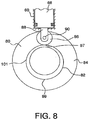
- the cam surface of the cam member ring 82 has a radius that varies about the ring 82 between a minimum radius at location 97 and a maximum radius at location 99 opposite from location 97.
- the varying radius defines a ramped portion 101 of the cam surface in which the radius increases from location 97 to location 99.
- the increasing radius in the ramped portion 101 of the cam surface drives the cylinder rod 66 outwardly when the cam member 80 is rotated with respect to the differential housing 20 to pressurize a hydraulic fluid in the master cylinder chamber 62.
- the cam is preferably symmetrical in design to provide operation in both forward and reverse directions.
- the pump assembly 16 also includes an armature plate 98 and a coil 100 received on the pinion input shaft 12 such that the armature plate 98 is located between the coil 100 and the cam member 80.
- the coil 100 is disposed about the input shaft 12 such that the shaft 12 can rotate relative to the coil 100.
- the coil 100 generates a magnetic field when activated that attracts the armature plate 98 to the coil 100.
- the armature plate 98 includes splines 104 about a central opening 102 which engage with mating splines 106 on the pinion input shaft 12 such that the armature plate 98 rotates with the pinion input shaft 12.
- the engagement between the splines 104, 106 allows for a limited amount of longitudinal movement of the armature plate 98 with respect to the pinion input shaft 12.
- the armature plate may be formed as an integral raised portion of the shaft.
- the pump assembly 16 includes a coil-activated condition and a coil-inactivated condition.
- the coil-inactivated condition the rotation of the pinion input shaft 12 and armature plate 98 with respect to the differential housing 20 has substantially no effect on the cam member 80.
- the coil 100 is energized creating a magnetic field.
- the magnetic field from the coil 100 causes the armature plate 98 and cam member 80 to be drawn towards the coil 100 resulting in contact between the armature plate 98 and the back plate 84 of cam member 80. Friction and magnetic forces cause the cam member 80 to rotate with the armature plate 98 with respect to the differential housing 20 when the armature plate 98 is rotated by the pinion input shaft 12.
- the member 80 when the pump assembly 16 is in the coil-inactivated condition, the member 80 is positioned with respect to the master cylinder 60 such that the roller disc 86 contacts the cam surface of the cam member ring 82 potentially adjacent location 97. In this position, the relatively reduced radius of the surface adjacent location 97 allows the spring 94 to bias the cylinder rod 66 away from the cover 74. As shown in Figure 7 , an inward end of the cylinder rod 66 in this position is located adjacent to, and potentially in contact with, the inward end wall 92 of the master cylinder 60. This maximizes the volume within the master cylinder chamber 62 between the cylinder rod 66 and the cover 74. In this position, the hydraulic fluid located within the interior chamber 62 is not pressurized. While the pump assembly 16 is in the coil-inactivated condition, the cam member 80 is not engaged with the input shaft. As such, there is no direct rotation of the cam member 80 by the input shaft. Accordingly, the cylinder rod is not reciprocated within the master cylinder.
- the cam member 80 rotates with the armature plate 98 which, in turn, is engaged with the input shaft.
- the member ring 82 rotates, causing the roller disc 86 to ride up the ramped portion 101.
- the contact between the roller disc 86 and the ramped portion 101 drives the cylinder rod 66 toward the cover, thereby pressurizing the hydraulic fluid within the interior chamber 62.
- the pressurization of the fluid within the master cylinder chamber 62 creates a reaction force between the roller disc 86 and the cam member ring 82.
- the profile of the cam member ring 82 is preferably dimensioned to cause the cam member 80 and armature plate 98 to slip with respect to each other in the coil-activated condition when the pressure within the master cylinder reaches a threshold level. At this level, the force that the roller disc 86 applies to the cam member ring 82 overcomes the frictional drag caused by the coil, thus permitting the input shaft and the armature plate to rotate relative to the cam member 80.
- the point at which this threshold occurs is schematically shown as location 105 along the ramped portion 101 between location 97 and location 99.
- the magnitude of the pressure generated in the hydraulic fluid by the pump assembly 16 can be adjusted by varying the distance 107 that the cylinder rod 66 travels towards the master cylinder cover 74 from the coil-inactivated position of Figure 7 .
- This travel distance 107 of the cylinder rod 66 is hereinafter referred to as the "stroke distance”.
- the magnitude of the friction forces generated between the armature plate 98 and the cam member back plate 84 can be varied by varying input voltage to the coil 100. In this manner, the point at which slippage between the cam member 80 and the armature plate 98 occurs can be varied to adjust the rotation of the cam member 80, thereby adjusting the stroke distance 107 of cylinder rod 66. For example, a reduction of the coil voltage reduces the cam member rotation thereby reducing the stroke distance 107 and the associated hydraulic pressure.
- the stroke distance 107 of the cylinder rod 66 could be controlled mechanically to force the slippage to occur at the predetermined location 105 rather than in the above-described manner.
- a positive stop (such as a wall) could be included on the ramped portion 101 of the cam member ring 82 at the predetermined location 105 thereby preventing further rotation of the cam member 80 with respect to the differential housing 20.
- the cam member could rotate continuously, causing the cylinder rod to repeatedly pressurize the hydraulic fluid.
- the surface of the cam member ring can be formed with multiple minimum and maximum radii, thus providing multiple low and high points on the cam profile and allowing multiple reciprocations for each rotation of the cam member. Suitable valving would be necessary to control the maintenance and supply of the pressurized fluid.
- the cam member can be replaced with a motorized pump, such as a continuous flow DC-operated pump, which would provide the pressure to the system.
- a reservoir would be used to store and supply the fluid.
- the master cylinder 60 in the illustrated exemplary embodiment includes a main body 109 that defines the interior chamber 62 and an elongated extension 108 extending from the main body 109 at an oblique angle with respect to a central axis of the interior chamber 62.
- the master cylinder 60 includes a flange 111 located at a terminal end of the extension 108.
- the flange 111 includes a pair of openings 113 for receiving two of the bolts 64 that secure the master cylinder 60 to the differential housing 20. Additional bolts may be used to further attach the main body 109 to the differential housing.
- the interior chamber 62 of the master cylinder 60 is preferably in fluid communication with the hydraulic pistons 58. In this manner, pressure generated in the master cylinder 60 can be transmitted to the clutch pack assemblies 42 contained within the interior of the differential housing as part of a backdriving feature.
- the use of the clutch pack assemblies to provide a backdriving feature is described in U.S. Pat. No. 6,622,837 .
- the extension 108 of the master cylinder 60 defines an internal passage communicating with the interior chamber 62 of master cylinder 60.
- a fluid passage is provided from the internal passage of the extension 108 through internal passages 110 in the differential housing to the clutch pack assemblies. As shown in Figure 3 , the internal passages 110 of the differential housing 20 extend to communicate with the hydraulic pistons 58.
- the pistons 58 are linked to the master cylinder interior chamber 62 for receipt of pressure that is transmitted from the master cylinder 60 in the hydraulic fluid.
- a hydraulic line can run externally from the master cylinder to the hydraulic piston 58.
- the pump assembly 16 includes a fill reservoir 112 connected to the master cylinder 60.
- the fill reservoir 112 defines an interior space 114 for receiving the hydraulic fluid.
- a cap 116 threadedly engages the fill reservoir 112 to enclose the interior space 114 of the fill reservoir 112.
- a diaphragm 118 is located between the cap 116 and the fill reservoir 112 to seal the interior space 114 of the reservoir when the cap 116 is threadedly engaged to the fill reservoir 112 and to keep the pressure atmospheric within the reservoir.
- Activation of the coil may be manually controlled through a control system, such as an activation (e.g., toggle or pushbutton) switch.
- the switch can be located remote from the gear case in any suitable location on the vehicle.
- the coil may be automatically activated upon activation of the backdrive as described in U.S. Pat. No. 6,622,837 .
- the pump assembly 120 includes a master cylinder 122 having mounting flanges 124.
- the mounting flanges 124 are adapted to receive bolts to secure the master cylinder 122 to a differential housing. This is similar to the above-described master cylinder 60, which is secured to the differential housing 20 of pump assembly 16 by bolts 64.
- the pump assembly 120 includes a cylinder rod 126 slidably located within an interior chamber 128 of the master cylinder 122, a follower in the form of a roller disc 130 mounted at an end of the cylinder rod 126, and a compression spring 132 received in a recess in an end of the cylinder rod 126 opposite the roller disc 130.
- the pump assembly 120 also includes a pressure regulating system 134.
- the pressure regulating system 134 includes a shuttle valve 136 and a compensating valve 138 mounted within a housing 140.
- the shuttle valve 136 is a ball check valve communicating with the interior chamber 128 of the master cylinder 122 and mounted above the cylinder rod 126.
- the ball check valve 136 includes a ball 142 located within an interior of a substantially cylindrical valve body 144.
- the valve body 144 is vertically-oriented (in the point of view shown in Figures 10 and 11 ) such that the ball is movable vertically with respect to the housing 140 in which the valve body 144 is mounted.
- the body 144 of the ball check valve 136 includes a first port 146 defined at a lower end of the body 144 communicating with the master cylinder chamber 128 and a second port 148 at an opposite upper end of the body 144.
- the second port 148 of the shuttle valve body 144 communicates with passageways 150 of housing 140, which are described in greater detail below.
- the second port 148 is relatively small compared to the ball 142.
- the ball 142 and the second port 148 are adapted such that contact between the ball 142 and the valve body 144 at the second port 148 (e.g., when the ball 142 is driven upwardly by positive pressure generated within the master cylinder chamber 128) seals the second port 148.
- the sealing of the second port 148 prevents a fluid (e.g., air or hydraulic fluid) from exiting the master cylinder chamber 128 via the second port 148, thereby allowing pressure in the master cylinder chamber 128 to build above the cylinder rod 126.
- a fluid e.g., air or hydraulic fluid
- gravity forces acting on the ball 142 cause the ball 142 to drop out of contact with the valve body 144 at the second port 148.
- the shuttle valve 136 provides a spring-less construction having sealed and opened conditions.
- the compensating valve 138 of the pressure regulating system 134 includes a piston 152 slidably mounted within a piston chamber 154 of housing 140.
- a bottom port 156 defined in housing 140 below the piston 152 communicates at one end with the piston chamber 154 of housing 140 and at an opposite end with the master cylinder chamber 128.
- a compression spring 158 located in the piston chamber 154 contacts an upper surface of the piston 152 and a removable cover 160 at opposite ends of the spring 158. The spring 158 urges the piston towards a bottom end of the piston chamber 154 when the pump assembly 120 is in a relaxed condition (i.e., zero pressure in the master cylinder chamber 128).
- a pair of side ports in housing 140 include a first side port 164 and a second side port 166 located above the first side port 164 at a distance from the first side port 164.
- Each of the side ports 164, 166 communicates at one end with the piston chamber 154 and at an opposite end with one of the passageways 150 of housing 140.
- the pressure regulating system 134 is arranged in the following manner. As discussed above, pressure generated within the master cylinder chamber 128 drives the ball 142 of shuttle valve 136 upwardly to seal the second port 148 of shuttle valve. Pressurized fluid (e.g., air or hydraulic fluid) from the master cylinder chamber 128, however, will be directed into the piston chamber 154 of compensating valve 138 below the piston 152 via the bottom port 156. The receipt of the pressurized fluid in the piston chamber 154 will drive the piston 152 upwardly within the piston chamber 154. If the piston 152 of compensating valve 138 is upwardly displaced beyond the first side port 164, the pressurized fluid is then directed into the passageways 150 of housing 140 via the first side port 164.
- Pressurized fluid e.g., air or hydraulic fluid
- the passageways 150 of housing 140 are arranged to communicate with an exit fitting 168 that is secured to housing 140.
- the pressurized fluid directed into the housing passageways 150 from the compensating valve chamber 154 can be discharged from the housing 140 (e.g., to a reservoir that is not shown) via the exit fitting 168.
- the spring rate for compression spring 158 is selected such that the when the pressure behind the compensating valve piston 152 reaches an upper design pressure, the piston 152 will be sufficiently displaced to uncover the first side port 164 in the above described manner for communication between the piston chamber 154 and the housing passageways 150.
- the first side port is uncovered, the pressurized fluid is permitted to flow out of the compensating valve 138 via the first side port 164, thus reducing the pressure below the piston 152 in the piston chamber 154 and in the master cylinder chamber 128.
- the piston will accordingly be returned downwardly with respect to the housing 140 because of the biasing force of compression spring 158.
- the downwardly moving piston will cover the first side port 164 again to block the communication between the piston 154 and the housing passageways 150, thereby maintaining pressure below the piston 152.
- the second side port 166 which is located above the first side port 164, communicates with the housing passageways 150, allowing fluid to be directed to the exit fitting 168 from the piston chamber 154 (i.e., for discharge to a reservoir). The removal of the fluid via the second side port 166 in this manner prevents the fluid from becoming trapped in the piston chamber 154 above the piston 152 thereby ensuring proper operation of the compensating valve 138.
- the compensating valve 138 regulates the pressure generated within the master cylinder chamber 128 below a desired design pressure, thereby preventing pressure spikes within the pump assembly 120.
- the compensating valve 138 also functions as a pressure accumulator by directing pressurized fluid from the housing 140 to a reservoir.
Landscapes
- Engineering & Computer Science (AREA)
- General Engineering & Computer Science (AREA)
- Mechanical Engineering (AREA)
- Physics & Mathematics (AREA)
- Electromagnetism (AREA)
- Fluid Mechanics (AREA)
- Hydraulic Clutches, Magnetic Clutches, Fluid Clutches, And Fluid Joints (AREA)
- Retarders (AREA)
- Reciprocating Pumps (AREA)
Priority Applications (1)
| Application Number | Priority Date | Filing Date | Title |
|---|---|---|---|
| PL07795017T PL2024656T3 (pl) | 2006-06-08 | 2007-05-18 | Pompa samowzbudzająca do sprzęgła nadbiegowego |
Applications Claiming Priority (2)
| Application Number | Priority Date | Filing Date | Title |
|---|---|---|---|
| US11/449,109 US7410042B2 (en) | 2006-06-08 | 2006-06-08 | Self-energizing pump for overrunning clutch |
| PCT/US2007/011883 WO2007145766A2 (en) | 2006-06-08 | 2007-05-18 | Self-energizing pump for overrunning clutch |
Publications (3)
| Publication Number | Publication Date |
|---|---|
| EP2024656A2 EP2024656A2 (en) | 2009-02-18 |
| EP2024656A4 EP2024656A4 (en) | 2017-03-08 |
| EP2024656B1 true EP2024656B1 (en) | 2018-07-25 |
Family
ID=38822203
Family Applications (1)
| Application Number | Title | Priority Date | Filing Date |
|---|---|---|---|
| EP07795017.8A Active EP2024656B1 (en) | 2006-06-08 | 2007-05-18 | Self-energizing pump for overrunning clutch |
Country Status (7)
| Country | Link |
|---|---|
| US (1) | US7410042B2 (pl) |
| EP (1) | EP2024656B1 (pl) |
| AU (1) | AU2007259335B2 (pl) |
| CA (1) | CA2654051C (pl) |
| ES (1) | ES2696123T3 (pl) |
| PL (1) | PL2024656T3 (pl) |
| WO (1) | WO2007145766A2 (pl) |
Families Citing this family (22)
| Publication number | Priority date | Publication date | Assignee | Title |
|---|---|---|---|---|
| US9003925B2 (en) * | 2011-08-10 | 2015-04-14 | Gkn Driveline North America, Inc. | Twin electronic torque management device |
| US8857589B2 (en) * | 2011-11-29 | 2014-10-14 | The Hilliard Corporation | Friction disk mechanism for bi-directional overrunning clutch |
| US9272620B2 (en) | 2012-07-31 | 2016-03-01 | The Hilliard Corporation | True four wheel drive system for vehicle |
| US9719567B2 (en) * | 2014-10-20 | 2017-08-01 | Deere & Company | Mechanical front wheel drive roller wedging control system |
| US9428051B1 (en) | 2015-07-21 | 2016-08-30 | American Axle & Manufacturing, Inc. | Driveline actuator powered by synchronization event |
| EP3318775B1 (en) * | 2016-11-03 | 2022-07-13 | Hamilton Sundstrand Corporation | Apparatus for torque limiting device |
| CN108331898A (zh) * | 2018-03-14 | 2018-07-27 | 长春天火汽车制造有限公司 | 超越离合器式电控限滑差速驱动桥 |
| SE541427C2 (en) * | 2018-08-08 | 2019-10-01 | C Falk Remote Control Ab | Torque-limiting clutch comprising an electric control system |
| SE541428C2 (en) * | 2018-08-08 | 2019-10-01 | C Falk Remote Control Ab | Torque-limiting clutch comprising a release trigger mechanism |
| CN113498459B (zh) | 2019-02-20 | 2024-05-31 | 蒂姆工业公司 | 具有双向超越离合器的差速器 |
| WO2020172428A1 (en) | 2019-02-20 | 2020-08-27 | Team Industries, Inc. | Drivetrain layout with cvt |
| US10883599B2 (en) * | 2019-05-23 | 2021-01-05 | Schaeffler Technologies AG & Co. KG | Hydraulic piston assembly |
| US11499608B2 (en) * | 2019-06-21 | 2022-11-15 | Team Industries, Inc. | Integrated launch clutch and drive sheave for steel belt continuously variable transmission |
| US11543006B2 (en) | 2019-06-21 | 2023-01-03 | Team Industries, Inc. | Variable torque limiting clutch for a steel belt continuously variable transmission |
| WO2021180368A1 (en) * | 2020-03-10 | 2021-09-16 | Eaton Intelligent Power Limited | Threaded connection to carrier for hydraulic connection to a case with an externally mounted plenum tube |
| US11131350B1 (en) * | 2020-06-17 | 2021-09-28 | The Hilliard Corporation | Power transmitting clutch and disconnect |
| KR20210156929A (ko) * | 2020-06-18 | 2021-12-28 | 현대자동차주식회사 | 하이브리드 차량의 파워트레인 |
| US11828354B2 (en) | 2021-05-28 | 2023-11-28 | Team Industries, Inc. | Overrunning clutch differential with a locking mechanism |
| US11592094B2 (en) | 2021-05-28 | 2023-02-28 | Team Industries, Inc. | Differential having an overrunning clutch with inertial compensation tuning |
| US12110951B2 (en) | 2021-07-12 | 2024-10-08 | Team Industries, Inc. | Double clutch reverse and active torque management system |
| US12467533B2 (en) | 2023-10-18 | 2025-11-11 | Team Industries, Inc. | High-low shifting active torque management continuously variable transmission system |
| CN120716434A (zh) * | 2025-08-08 | 2025-09-30 | 福建宏大时代新能源科技有限公司 | 一种纯电地下运矿车动力总成 |
Family Cites Families (36)
| Publication number | Priority date | Publication date | Assignee | Title |
|---|---|---|---|---|
| US3124972A (en) * | 1964-03-17 | Differential mechanism | ||
| DE430321C (de) | 1923-07-15 | 1926-06-15 | Arnold Seidel | Zwischen dem Antriebsgliede und jeder Treibradwelle eingeschaltete Lamellenkupplung |
| US1823389A (en) * | 1926-10-30 | 1931-09-15 | Lavaud Dimitri Sensaud De | Differential gear provided with propping rollers |
| US2865228A (en) * | 1954-05-03 | 1958-12-23 | Albert A Weismann | Positive drive differential for motor vehicles |
| US2908181A (en) * | 1955-11-03 | 1959-10-13 | Borg Warner | Transmission for automotive vehicles |
| US3262526A (en) * | 1964-03-19 | 1966-07-26 | Ingersoll Rand Co | Duodirectional overrunning clutch |
| US3447396A (en) * | 1967-06-09 | 1969-06-03 | James M Seliger | Differential mechanism |
| US3500977A (en) * | 1968-02-21 | 1970-03-17 | Torrington Co | Retainer for overrunning clutch with spring insert |
| DE6923286U (de) * | 1969-06-11 | 1970-11-12 | Schaeffler Ohg Industriewerk | Klemmrollen - freilauf |
| US3581597A (en) * | 1970-04-29 | 1971-06-01 | Hy Torq Corp | Differential drive mechanism |
| US3700082A (en) * | 1970-07-09 | 1972-10-24 | Hy Torq Corp | Differential drive mechanism |
| US3863742A (en) * | 1973-08-08 | 1975-02-04 | Torrington Co | Retainer for overrunning clutch |
| US3935753A (en) * | 1975-02-18 | 1976-02-03 | Warn Industries, Inc. | Positive drive differential |
| FR2470307B1 (fr) * | 1979-11-19 | 1987-07-03 | Honda Motor Co Ltd | Mecanisme d'embrayage pour systeme de transmission de forces |
| US4434878A (en) * | 1979-11-19 | 1984-03-06 | Honda Giken Kogyo Kabushiki Kaisha | Clutch mechanism for power transmission system |
| JPS5986747A (ja) | 1982-11-10 | 1984-05-19 | Fuji Heavy Ind Ltd | フリ−ホイ−ル式車軸差動装置 |
| DE3427347C2 (de) * | 1984-07-25 | 1995-01-26 | Schaeffler Waelzlager Kg | Freilaufkäfig aus polymerem Werkstoff |
| US4710106A (en) * | 1984-11-26 | 1987-12-01 | Nippondenso Co., Ltd. | Volume controlling device for variable volume pump |
| JPS6294421A (ja) * | 1985-10-18 | 1987-04-30 | Fuji Heavy Ind Ltd | 車両の後輪駆動装置 |
| US4782720A (en) * | 1985-11-12 | 1988-11-08 | Tochigifujisangyo Kabushikigaisha | Power transmission unit |
| JPS62238115A (ja) * | 1986-04-07 | 1987-10-19 | Fuji Heavy Ind Ltd | 4輪駆動車の駆動軸選択装置 |
| US5036939A (en) * | 1987-08-28 | 1991-08-06 | Polaris Industries L.P. | Multiple axle drive vehicle with overrunning roller clutch hubs |
| JPH0514014Y2 (pl) * | 1988-04-11 | 1993-04-14 | ||
| JPH0237034A (ja) * | 1988-07-27 | 1990-02-07 | Toyoda Mach Works Ltd | 駆動力配分装置 |
| JPH03243421A (ja) * | 1990-02-19 | 1991-10-30 | Mazda Motor Corp | 車両の動力伝達装置 |
| US5025902A (en) * | 1990-01-04 | 1991-06-25 | Aichi Kikai Kogyo Kabushiki Kaisha | Bidirectional differential clutch |
| US5070745A (en) * | 1990-12-24 | 1991-12-10 | Lindsey Kelly D | Asymmetrical differential drive |
| US5203232A (en) * | 1991-02-18 | 1993-04-20 | Ntn Corporation | Rotation transmitting device |
| CN1074659A (zh) * | 1992-01-25 | 1993-07-28 | 高兴龙 | 车辆高效节能多功能系统 |
| DE4207641C2 (de) * | 1992-03-11 | 2000-07-13 | Bosch Gmbh Robert | Reibungsbremse, insbesondere Scheibenbremse, für Fahrzeuge sowie Verfahren zum Abbremsen eines Fahrzeugs |
| US5411123A (en) * | 1993-12-27 | 1995-05-02 | Ford Motor Company | Cartridge ball check valve having integral filter for an automatic transmission clutch |
| US5511642A (en) * | 1994-04-11 | 1996-04-30 | Chrysler Corporation | Overrunning clutch assembly |
| US5845546A (en) * | 1997-04-04 | 1998-12-08 | Borg-Warner Automotive, Inc. | Multiple chamber twin clutch axle |
| US5971123A (en) * | 1998-10-09 | 1999-10-26 | Hilliard Corporation | Bi-directional overrunning clutch |
| US6092634A (en) * | 1999-03-08 | 2000-07-25 | Borgwarner Inc. | Compliant cage for a roller-type bi-directional one-way clutch mechanism |
| US6622837B2 (en) * | 2000-11-17 | 2003-09-23 | The Hilliard Corporation | Bi-directional overrunning clutch with automatic backdrive |
-
2006
- 2006-06-08 US US11/449,109 patent/US7410042B2/en active Active
-
2007
- 2007-05-18 ES ES07795017T patent/ES2696123T3/es active Active
- 2007-05-18 PL PL07795017T patent/PL2024656T3/pl unknown
- 2007-05-18 EP EP07795017.8A patent/EP2024656B1/en active Active
- 2007-05-18 CA CA2654051A patent/CA2654051C/en active Active
- 2007-05-18 WO PCT/US2007/011883 patent/WO2007145766A2/en not_active Ceased
- 2007-05-18 AU AU2007259335A patent/AU2007259335B2/en active Active
Also Published As
| Publication number | Publication date |
|---|---|
| EP2024656A4 (en) | 2017-03-08 |
| PL2024656T3 (pl) | 2018-12-31 |
| WO2007145766A2 (en) | 2007-12-21 |
| EP2024656A2 (en) | 2009-02-18 |
| US20070286743A1 (en) | 2007-12-13 |
| WO2007145766A3 (en) | 2008-02-28 |
| CA2654051A1 (en) | 2007-12-21 |
| CA2654051C (en) | 2013-11-05 |
| AU2007259335A1 (en) | 2007-12-21 |
| AU2007259335A2 (en) | 2009-02-26 |
| AU2007259335B2 (en) | 2011-09-29 |
| ES2696123T3 (es) | 2019-01-14 |
| US7410042B2 (en) | 2008-08-12 |
Similar Documents
| Publication | Publication Date | Title |
|---|---|---|
| EP2024656B1 (en) | Self-energizing pump for overrunning clutch | |
| US6622837B2 (en) | Bi-directional overrunning clutch with automatic backdrive | |
| US6629590B2 (en) | Spring assembly for a bi-directional overrunning clutch | |
| US6041903A (en) | Hydraulic coupling for vehicular power transfer systems | |
| US6945374B2 (en) | Active torque coupling with hydraulically-actuated ball ramp clutch assembly | |
| EP1020655B1 (en) | Hydromechanical coupling with torque-limiting and temperature-sensitive unloading features | |
| US4846299A (en) | Coupling assemblies | |
| EP1027545A1 (en) | Self-contained hydraulic coupling | |
| JP2837169B2 (ja) | 2本の回転自在シャフト間の相対回転運動抵抗装置 | |
| EP0084255A2 (en) | Drive axle assembly | |
| CN101479496B (zh) | 用于液压操纵的三位置控制螺线管 | |
| US8763777B2 (en) | Hydraulic coupling | |
| US4452100A (en) | Differential speed limiting device | |
| US20060065509A1 (en) | Self bleeding system | |
| KR20190001653A (ko) | 드래그 토크 감소를 위한 리어디프부 및 커플링부 일체형 케이스 어셈블리 | |
| KR102603706B1 (ko) | 차량의 동력전달 제어장치 | |
| EP0315443A1 (en) | Improvements in vehicle disc brakes of the liquid cooled type | |
| JPH02267060A (ja) | 車両用アンチロック制御装置 | |
| JPH09236143A (ja) | 差動感応型油圧カップリング装置 | |
| JPH09236145A (ja) | 差動感応型油圧カップリング装置 | |
| JPH09236146A (ja) | 差動感応型油圧カップリング装置 |
Legal Events
| Date | Code | Title | Description |
|---|---|---|---|
| PUAI | Public reference made under article 153(3) epc to a published international application that has entered the european phase |
Free format text: ORIGINAL CODE: 0009012 |
|
| 17P | Request for examination filed |
Effective date: 20081124 |
|
| AK | Designated contracting states |
Kind code of ref document: A2 Designated state(s): AT BE BG CH CY CZ DE DK EE ES FI FR GB GR HU IE IS IT LI LT LU LV MC MT NL PL PT RO SE SI SK TR |
|
| AX | Request for extension of the european patent |
Extension state: AL BA HR MK RS |
|
| RIN1 | Information on inventor provided before grant (corrected) |
Inventor name: COWEN, MATTHEW, J. Inventor name: HEATH, KELLY, P. Inventor name: OCHAB, DAVID, C. Inventor name: BREWER, BRENDAN Inventor name: HASSON, JOHN, MICHAEL, JR. |
|
| DAX | Request for extension of the european patent (deleted) | ||
| A4 | Supplementary search report drawn up and despatched |
Effective date: 20170208 |
|
| RIC1 | Information provided on ipc code assigned before grant |
Ipc: F04B 53/00 20060101ALI20170202BHEP Ipc: F16D 41/08 20060101ALI20170202BHEP Ipc: F16H 48/18 20060101ALI20170202BHEP Ipc: F16H 48/30 20120101ALI20170202BHEP Ipc: F16D 28/00 20060101ALI20170202BHEP Ipc: F04B 49/06 20060101ALI20170202BHEP Ipc: F16D 25/08 20060101ALI20170202BHEP Ipc: F16H 48/34 20120101ALI20170202BHEP Ipc: F16H 48/12 20120101ALI20170202BHEP Ipc: F16H 48/32 20120101ALI20170202BHEP Ipc: F16H 48/16 20060101ALI20170202BHEP Ipc: F16H 48/20 20120101ALI20170202BHEP Ipc: F16H 48/42 20120101ALI20170202BHEP Ipc: F16D 43/284 20060101AFI20170202BHEP Ipc: F04B 9/02 20060101ALI20170202BHEP Ipc: F04B 1/04 20060101ALI20170202BHEP Ipc: F16D 27/112 20060101ALI20170202BHEP Ipc: F16H 48/22 20060101ALI20170202BHEP Ipc: F16H 48/19 20120101ALI20170202BHEP |
|
| GRAP | Despatch of communication of intention to grant a patent |
Free format text: ORIGINAL CODE: EPIDOSNIGR1 |
|
| STAA | Information on the status of an ep patent application or granted ep patent |
Free format text: STATUS: GRANT OF PATENT IS INTENDED |
|
| INTG | Intention to grant announced |
Effective date: 20180215 |
|
| GRAJ | Information related to disapproval of communication of intention to grant by the applicant or resumption of examination proceedings by the epo deleted |
Free format text: ORIGINAL CODE: EPIDOSDIGR1 |
|
| STAA | Information on the status of an ep patent application or granted ep patent |
Free format text: STATUS: REQUEST FOR EXAMINATION WAS MADE |
|
| GRAR | Information related to intention to grant a patent recorded |
Free format text: ORIGINAL CODE: EPIDOSNIGR71 |
|
| GRAS | Grant fee paid |
Free format text: ORIGINAL CODE: EPIDOSNIGR3 |
|
| STAA | Information on the status of an ep patent application or granted ep patent |
Free format text: STATUS: GRANT OF PATENT IS INTENDED |
|
| GRAA | (expected) grant |
Free format text: ORIGINAL CODE: 0009210 |
|
| STAA | Information on the status of an ep patent application or granted ep patent |
Free format text: STATUS: THE PATENT HAS BEEN GRANTED |
|
| INTC | Intention to grant announced (deleted) | ||
| AK | Designated contracting states |
Kind code of ref document: B1 Designated state(s): AT BE BG CH CY CZ DE DK EE ES FI FR GB GR HU IE IS IT LI LT LU LV MC MT NL PL PT RO SE SI SK TR |
|
| INTG | Intention to grant announced |
Effective date: 20180618 |
|
| REG | Reference to a national code |
Ref country code: GB Ref legal event code: FG4D |
|
| REG | Reference to a national code |
Ref country code: CH Ref legal event code: EP |
|
| REG | Reference to a national code |
Ref country code: AT Ref legal event code: REF Ref document number: 1022106 Country of ref document: AT Kind code of ref document: T Effective date: 20180815 |
|
| REG | Reference to a national code |
Ref country code: IE Ref legal event code: FG4D |
|
| REG | Reference to a national code |
Ref country code: DE Ref legal event code: R096 Ref document number: 602007055521 Country of ref document: DE |
|
| REG | Reference to a national code |
Ref country code: NL Ref legal event code: MP Effective date: 20180725 |
|
| REG | Reference to a national code |
Ref country code: LT Ref legal event code: MG4D |
|
| REG | Reference to a national code |
Ref country code: CH Ref legal event code: PK Free format text: BERICHTIGUNGEN |
|
| PG25 | Lapsed in a contracting state [announced via postgrant information from national office to epo] |
Ref country code: NL Free format text: LAPSE BECAUSE OF FAILURE TO SUBMIT A TRANSLATION OF THE DESCRIPTION OR TO PAY THE FEE WITHIN THE PRESCRIBED TIME-LIMIT Effective date: 20180725 |
|
| RIC2 | Information provided on ipc code assigned after grant |
Ipc: F16H 48/22 20060101ALI20170202BHEP Ipc: F16D 28/00 20060101ALI20170202BHEP Ipc: F16H 48/42 20120101ALI20170202BHEP Ipc: F04B 1/04 20060101ALI20170202BHEP Ipc: F16H 48/20 20120101ALI20170202BHEP Ipc: F16D 25/08 20060101ALI20170202BHEP Ipc: F16D 41/08 20060101ALI20170202BHEP Ipc: F16D 27/112 20060101ALI20170202BHEP Ipc: F04B 53/00 20060101ALI20170202BHEP Ipc: F04B 9/02 20060101ALI20170202BHEP Ipc: F16H 48/18 20060101ALI20170202BHEP Ipc: F16D 43/284 20060101AFI20170202BHEP Ipc: F04B 49/06 20060101ALI20170202BHEP Ipc: F16H 48/30 20120101ALI20170202BHEP Ipc: F16H 48/12 20120101ALI20170202BHEP Ipc: F16H 48/32 20120101ALI20170202BHEP Ipc: F16H 48/34 20120101ALI20170202BHEP Ipc: F16H 48/16 20060101ALI20170202BHEP Ipc: F16H 48/19 20120101ALI20170202BHEP |
|
| REG | Reference to a national code |
Ref country code: ES Ref legal event code: FG2A Ref document number: 2696123 Country of ref document: ES Kind code of ref document: T3 Effective date: 20190114 |
|
| REG | Reference to a national code |
Ref country code: AT Ref legal event code: MK05 Ref document number: 1022106 Country of ref document: AT Kind code of ref document: T Effective date: 20180725 |
|
| PG25 | Lapsed in a contracting state [announced via postgrant information from national office to epo] |
Ref country code: BG Free format text: LAPSE BECAUSE OF FAILURE TO SUBMIT A TRANSLATION OF THE DESCRIPTION OR TO PAY THE FEE WITHIN THE PRESCRIBED TIME-LIMIT Effective date: 20181025 Ref country code: SE Free format text: LAPSE BECAUSE OF FAILURE TO SUBMIT A TRANSLATION OF THE DESCRIPTION OR TO PAY THE FEE WITHIN THE PRESCRIBED TIME-LIMIT Effective date: 20180725 Ref country code: FI Free format text: LAPSE BECAUSE OF FAILURE TO SUBMIT A TRANSLATION OF THE DESCRIPTION OR TO PAY THE FEE WITHIN THE PRESCRIBED TIME-LIMIT Effective date: 20180725 Ref country code: LT Free format text: LAPSE BECAUSE OF FAILURE TO SUBMIT A TRANSLATION OF THE DESCRIPTION OR TO PAY THE FEE WITHIN THE PRESCRIBED TIME-LIMIT Effective date: 20180725 Ref country code: AT Free format text: LAPSE BECAUSE OF FAILURE TO SUBMIT A TRANSLATION OF THE DESCRIPTION OR TO PAY THE FEE WITHIN THE PRESCRIBED TIME-LIMIT Effective date: 20180725 Ref country code: GR Free format text: LAPSE BECAUSE OF FAILURE TO SUBMIT A TRANSLATION OF THE DESCRIPTION OR TO PAY THE FEE WITHIN THE PRESCRIBED TIME-LIMIT Effective date: 20181026 Ref country code: IS Free format text: LAPSE BECAUSE OF FAILURE TO SUBMIT A TRANSLATION OF THE DESCRIPTION OR TO PAY THE FEE WITHIN THE PRESCRIBED TIME-LIMIT Effective date: 20181125 |
|
| REG | Reference to a national code |
Ref country code: CH Ref legal event code: PK Free format text: BERICHTIGUNGEN |
|
| RIC2 | Information provided on ipc code assigned after grant |
Ipc: F04B 9/02 20060101ALI20170202BHEP Ipc: F16H 48/16 20060101ALI20170202BHEP Ipc: F16H 48/18 20060101ALI20170202BHEP Ipc: F04B 53/00 20060101ALI20170202BHEP Ipc: F16H 48/32 20120101ALI20170202BHEP Ipc: F16D 41/08 20060101ALI20170202BHEP Ipc: F16H 48/19 20120101ALI20170202BHEP Ipc: F16H 48/22 20060101ALI20170202BHEP Ipc: F16H 48/34 20120101ALI20170202BHEP Ipc: F16H 48/20 20120101ALI20170202BHEP Ipc: F04B 1/04 20060101ALI20170202BHEP Ipc: F16H 48/12 20120101ALI20170202BHEP Ipc: F16H 48/30 20120101ALI20170202BHEP Ipc: F04B 49/06 20060101ALI20170202BHEP Ipc: F16D 28/00 20060101ALI20170202BHEP Ipc: F16D 43/284 20060101AFI20170202BHEP Ipc: F16H 48/42 20120101ALI20170202BHEP Ipc: F16D 27/112 20060101ALI20170202BHEP Ipc: F16D 25/08 20060101ALI20170202BHEP |
|
| PG25 | Lapsed in a contracting state [announced via postgrant information from national office to epo] |
Ref country code: LV Free format text: LAPSE BECAUSE OF FAILURE TO SUBMIT A TRANSLATION OF THE DESCRIPTION OR TO PAY THE FEE WITHIN THE PRESCRIBED TIME-LIMIT Effective date: 20180725 |
|
| REG | Reference to a national code |
Ref country code: DE Ref legal event code: R097 Ref document number: 602007055521 Country of ref document: DE |
|
| PG25 | Lapsed in a contracting state [announced via postgrant information from national office to epo] |
Ref country code: EE Free format text: LAPSE BECAUSE OF FAILURE TO SUBMIT A TRANSLATION OF THE DESCRIPTION OR TO PAY THE FEE WITHIN THE PRESCRIBED TIME-LIMIT Effective date: 20180725 Ref country code: RO Free format text: LAPSE BECAUSE OF FAILURE TO SUBMIT A TRANSLATION OF THE DESCRIPTION OR TO PAY THE FEE WITHIN THE PRESCRIBED TIME-LIMIT Effective date: 20180725 Ref country code: CZ Free format text: LAPSE BECAUSE OF FAILURE TO SUBMIT A TRANSLATION OF THE DESCRIPTION OR TO PAY THE FEE WITHIN THE PRESCRIBED TIME-LIMIT Effective date: 20180725 |
|
| PG25 | Lapsed in a contracting state [announced via postgrant information from national office to epo] |
Ref country code: SK Free format text: LAPSE BECAUSE OF FAILURE TO SUBMIT A TRANSLATION OF THE DESCRIPTION OR TO PAY THE FEE WITHIN THE PRESCRIBED TIME-LIMIT Effective date: 20180725 Ref country code: DK Free format text: LAPSE BECAUSE OF FAILURE TO SUBMIT A TRANSLATION OF THE DESCRIPTION OR TO PAY THE FEE WITHIN THE PRESCRIBED TIME-LIMIT Effective date: 20180725 |
|
| PLBE | No opposition filed within time limit |
Free format text: ORIGINAL CODE: 0009261 |
|
| STAA | Information on the status of an ep patent application or granted ep patent |
Free format text: STATUS: NO OPPOSITION FILED WITHIN TIME LIMIT |
|
| 26N | No opposition filed |
Effective date: 20190426 |
|
| PG25 | Lapsed in a contracting state [announced via postgrant information from national office to epo] |
Ref country code: SI Free format text: LAPSE BECAUSE OF FAILURE TO SUBMIT A TRANSLATION OF THE DESCRIPTION OR TO PAY THE FEE WITHIN THE PRESCRIBED TIME-LIMIT Effective date: 20180725 |
|
| REG | Reference to a national code |
Ref country code: CH Ref legal event code: PL |
|
| PG25 | Lapsed in a contracting state [announced via postgrant information from national office to epo] |
Ref country code: LI Free format text: LAPSE BECAUSE OF NON-PAYMENT OF DUE FEES Effective date: 20190531 Ref country code: MC Free format text: LAPSE BECAUSE OF FAILURE TO SUBMIT A TRANSLATION OF THE DESCRIPTION OR TO PAY THE FEE WITHIN THE PRESCRIBED TIME-LIMIT Effective date: 20180725 Ref country code: CH Free format text: LAPSE BECAUSE OF NON-PAYMENT OF DUE FEES Effective date: 20190531 |
|
| REG | Reference to a national code |
Ref country code: BE Ref legal event code: MM Effective date: 20190531 |
|
| PG25 | Lapsed in a contracting state [announced via postgrant information from national office to epo] |
Ref country code: LU Free format text: LAPSE BECAUSE OF NON-PAYMENT OF DUE FEES Effective date: 20190518 |
|
| PG25 | Lapsed in a contracting state [announced via postgrant information from national office to epo] |
Ref country code: TR Free format text: LAPSE BECAUSE OF FAILURE TO SUBMIT A TRANSLATION OF THE DESCRIPTION OR TO PAY THE FEE WITHIN THE PRESCRIBED TIME-LIMIT Effective date: 20180725 |
|
| PG25 | Lapsed in a contracting state [announced via postgrant information from national office to epo] |
Ref country code: IE Free format text: LAPSE BECAUSE OF NON-PAYMENT OF DUE FEES Effective date: 20190518 |
|
| PG25 | Lapsed in a contracting state [announced via postgrant information from national office to epo] |
Ref country code: BE Free format text: LAPSE BECAUSE OF NON-PAYMENT OF DUE FEES Effective date: 20190531 |
|
| PG25 | Lapsed in a contracting state [announced via postgrant information from national office to epo] |
Ref country code: PT Free format text: LAPSE BECAUSE OF FAILURE TO SUBMIT A TRANSLATION OF THE DESCRIPTION OR TO PAY THE FEE WITHIN THE PRESCRIBED TIME-LIMIT Effective date: 20181125 |
|
| PG25 | Lapsed in a contracting state [announced via postgrant information from national office to epo] |
Ref country code: CY Free format text: LAPSE BECAUSE OF FAILURE TO SUBMIT A TRANSLATION OF THE DESCRIPTION OR TO PAY THE FEE WITHIN THE PRESCRIBED TIME-LIMIT Effective date: 20180725 |
|
| PG25 | Lapsed in a contracting state [announced via postgrant information from national office to epo] |
Ref country code: HU Free format text: LAPSE BECAUSE OF FAILURE TO SUBMIT A TRANSLATION OF THE DESCRIPTION OR TO PAY THE FEE WITHIN THE PRESCRIBED TIME-LIMIT; INVALID AB INITIO Effective date: 20070518 Ref country code: MT Free format text: LAPSE BECAUSE OF FAILURE TO SUBMIT A TRANSLATION OF THE DESCRIPTION OR TO PAY THE FEE WITHIN THE PRESCRIBED TIME-LIMIT Effective date: 20180725 |
|
| PGFP | Annual fee paid to national office [announced via postgrant information from national office to epo] |
Ref country code: DE Payment date: 20250325 Year of fee payment: 19 |
|
| PGFP | Annual fee paid to national office [announced via postgrant information from national office to epo] |
Ref country code: ES Payment date: 20250603 Year of fee payment: 19 |
|
| PGFP | Annual fee paid to national office [announced via postgrant information from national office to epo] |
Ref country code: IT Payment date: 20250422 Year of fee payment: 19 |
|
| PGFP | Annual fee paid to national office [announced via postgrant information from national office to epo] |
Ref country code: GB Payment date: 20260312 Year of fee payment: 20 |
|
| PGFP | Annual fee paid to national office [announced via postgrant information from national office to epo] |
Ref country code: FR Payment date: 20260309 Year of fee payment: 20 |
|
| PGFP | Annual fee paid to national office [announced via postgrant information from national office to epo] |
Ref country code: PL Payment date: 20260317 Year of fee payment: 20 |