EP2023443A2 - Steckeranschluss - Google Patents
Steckeranschluss Download PDFInfo
- Publication number
- EP2023443A2 EP2023443A2 EP08013499A EP08013499A EP2023443A2 EP 2023443 A2 EP2023443 A2 EP 2023443A2 EP 08013499 A EP08013499 A EP 08013499A EP 08013499 A EP08013499 A EP 08013499A EP 2023443 A2 EP2023443 A2 EP 2023443A2
- Authority
- EP
- European Patent Office
- Prior art keywords
- detent
- male
- plug connector
- recited
- plate
- Prior art date
- Legal status (The legal status is an assumption and is not a legal conclusion. Google has not performed a legal analysis and makes no representation as to the accuracy of the status listed.)
- Granted
Links
- 238000003780 insertion Methods 0.000 claims abstract description 15
- 230000037431 insertion Effects 0.000 claims abstract description 15
- 230000004913 activation Effects 0.000 claims description 8
- 238000002788 crimping Methods 0.000 description 6
- 230000013011 mating Effects 0.000 description 4
- 238000010276 construction Methods 0.000 description 2
- 230000014759 maintenance of location Effects 0.000 description 2
- 238000000034 method Methods 0.000 description 2
- 230000000717 retained effect Effects 0.000 description 2
- 238000005452 bending Methods 0.000 description 1
- 239000004020 conductor Substances 0.000 description 1
- 230000006378 damage Effects 0.000 description 1
- 230000000694 effects Effects 0.000 description 1
- 239000011343 solid material Substances 0.000 description 1
Images


Classifications
-
- H—ELECTRICITY
- H01—ELECTRIC ELEMENTS
- H01R—ELECTRICALLY-CONDUCTIVE CONNECTIONS; STRUCTURAL ASSOCIATIONS OF A PLURALITY OF MUTUALLY-INSULATED ELECTRICAL CONNECTING ELEMENTS; COUPLING DEVICES; CURRENT COLLECTORS
- H01R13/00—Details of coupling devices of the kinds covered by groups H01R12/70 or H01R24/00 - H01R33/00
- H01R13/40—Securing contact members in or to a base or case; Insulating of contact members
- H01R13/42—Securing in a demountable manner
- H01R13/436—Securing a plurality of contact members by one locking piece or operation
- H01R13/4361—Insertion of locking piece perpendicular to direction of contact insertion
- H01R13/4362—Insertion of locking piece perpendicular to direction of contact insertion comprising a temporary and a final locking position
Definitions
- the present invention relates to a plug connector in accordance with the preamble of Claim 1.
- the detent has a clip arm, whose deflection resistance opposes the male or female plug contact being inserted into the housing via a crimped cable and being locked there.
- This force employed for a locking insertion of a male or female plug contact may only be applied if the cable connected with this contact is relatively stiff, so that when it is inserted it does not buckle.
- a cable having a thinner cross-section will buckle, especially if it is in the form of braids, so that a tool must be used to achieve a locking insertion of this kind of contact.
- the detent for the plug connector has a first stage, a preliminary locking position, in which cables that buckle easily can be inserted without difficulty because they can overcome the relatively small deflection resistance of the detent without buckling.
- the detent is subsequently placed in its final locking position as the second stage.
- the detent can be immediately placed in its final locking position, in which it can be deflected by such a relatively stiff cable to lock the contact.
- a further advantage of the aforementioned measures according to the present invention lies in the fact that although the cables, and the male or female plug contacts, are held in the final locking position and therefore can no longer be pulled out, nevertheless they may be pulled out of the housing without difficulty undamaged after a backward motion of the detent from its final locking position into its preliminary locking position by the overcoming of a certain locking resistance.
- the contacts therefore can be both installed and removed without tools.
- the features in accordance with Claim 2 are provided, so that a simple manipulation of the detent is sufficient to move it into its two locking positions.
- Advantageous embodiments of the detent slider emerge from the features of one or more of Claims 3 to 5, whereby the detent can be brought in a simple manipulation from its final locking position back into its preliminary locking position.
- an individual detent notch or both detent notches can accomplish their function with respect to the locking reception of the detent collar of the male or female plug contact.
- the preliminary locking position of the rear detent notch is retained in limited fashion and that in the withdrawal direction of the detent, i.e., in the opposite direction, from the final locking step to the preliminary locking step, the front detent notch prevents an unintended complete removal of the slider from the insulating body.
- the features according to Claim 10 are provided, advantageously resulting in the fact that when a male or female plug contact is inserted into the insulating body the detent in its final locking position between the two guide bars can be deflected in spring-like fashion over the central area of the detent plate.
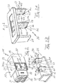
- Plug connector device 10 is made up of a plug connector 11 having female plug contacts 14 and a mating plug connector 12 having male plug contacts 15. Both in the case of plug connector 11 as well as in the case of mating plug connector 12, four female plug contacts 14 and male plug contacts 15, arranged in pairs so as to lie next to each other, i.e. forming a square, are arranged in one insulating body 13 or 16, which constitutes a housing.
- Insulating bodies 13 and 16 are configured so that they each with their front end 17 or 18 (female or male attachment) can plug into the other in locking fashion, whereby simultaneously the front ends of female plug contacts 14 and male plug contacts 15 are inserted into each other, and so that female plug contacts 14 and male plug contacts 15 that are connected in crimped fashion and are furnished with an un-depicted cable are inserted into boreholes 21 and 22 in rear ends 19 and 20 of plug connector 11 and mating plug connector 12 in a manner that is not depicted, and are retained in their respective insulating body 13 and 16 by a detent 23 and 24 or 25 and 26.
- Detent 24, depicted in detail in partial figures 3A and 3B has the shape of a detent slider 36, which has an activation plate 37, on which horizontally a guide plate 38 and two detent plate 39 and 40 are provided as one integral piece that protrudes perpendicularly, each detent plate being provided with detent elements 41.
- Guide plate 38 and detent plates 39 and 40 are each of equal length, whereby detent plates 39 and 40 as well as their detent elements 41 are identical.
- Guide plate 38 and exterior detent plate 40 are provided on the side edges on activation plate 37, which is essentially rectangular, whereas detent plate 39 is arranged roughly in the center.
- Guide plate 38 and detent plates 39, 40 are also configured so as to be rectangular, whereby the longitudinal side runs in direction A and B of the sliding motion.
- Detent elements 41 of detent plate 39 and 40 are arranged on the lateral surface that is facing guide plate 38 and central detent plate 39.
- Detent elements 41 which are identical in detent plates 39, 40, have a detent bar 42, which runs in the longitudinal direction of detent plates 39, 40 and is arranged roughly laterally in the center.
- the length of detent bar 42 roughly corresponds to the length of detent plate 39 and 40.
- detent bar 42 At the front end, in the direction of motion A or B, detent bar 42 has a guide bevel 43, which acts in direction of motion A and B, and on both sides a chamfer 44 and 45.
- Detent element 41 also has a front detent notch 46 in direction of motion A and B and a rear detent notch 47, which are arranged at a specific distance from each other.
- Front detent notch 46 is configured so as to be roughly wedge shaped, whereby the wedge surface is situated forward in the direction of motion, whereas rear detent notch 47 is configured so as to be roughly semicylindrical.
- Detent notches 46 and 47 protrude diagonally with respect to direction of motion A and B beyond guide surface 48 of detent bar 42.
- Detent elements 41 together constitute one integral piece along with detent plates 39 and 40, whereby detent slider 36 in its totality is configured in one piece and is made of plastic.
- Figure 2 depicts in greater detail the configuration of insulating body 13 and its main part 31 (which is identical to main part 32 of insulating body 16) for the reception through a longitudinal motion in the direction of arrow A and B of detent slider 36 of detent (here) 24.
- main part 31 of insulating body 13 is provided with a guide slot 58 for guide plate 38 and with detent slots 59 and 64 for detent plates 39 and 40, including detent bar 42. All slots 58 to 60 protrude through the wall of main part 31 transverse with respect to the longitudinal extension of boreholes 21 and, according to Figure 5 , over the entire diameter of boreholes 21.
- detent slots 59 and 60 each partially intersect assigned boreholes 21, whereas guide slot 58 runs past borehole 21.
- Slots 58 and 60 begin at the base of a recess 51 that is provided in relevant sidewall 28, in which activation plate 37 is accommodated in its final locking position.
- Recess 51 is open at front end 17 of insulating body 13, so that activation plate 37 can be grasped and moved in accordance with arrows A and B.
- Detent plates 39 and 40 each have on their side surface 52 facing away from detent elements 41 two parallel longitudinal bars 53 and 54, which essentially run over the entire length of detent plates 39, 40 and which are arranged in the vicinity of the transverse edges of detent plates 39, 40.
- Identically configured detent slots 59 and 60 are made up of a longitudinally running elongated rectangular slot part 61 and a transverse slot part 62, perpendicular thereto in the longitudinal center.
- the length of longitudinal slot part 61 corresponds to the width of detent plate 39, 40, whereas the width of longitudinal slot part 61 is equal to the thickness of detent plate 39, 40, including longitudinal bars 53, 54, as can be seen in Figure 4 .
- the width of transverse slot part 62 corresponds to the width of detent bar 42 of detent elements 41, which also applies to the depth of transverse slot part 62 in relation to the thickness of detent bar 42.
- clearance h of longitudinal slot part 61 and transverse slot part 62, added together, is equal to thickness d of detent plate 39, 40 plus that of longitudinal bars 53, 54 and of detent bar 42, in other words without the protruding amount of detent notches 46, 47.
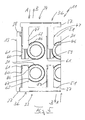
- detent slider 36 of respective detent 24 can occupy a first, or preliminary locking position, which is depicted in Figure 5 on top, and a final locking position, going further in the direction of motion A and B, which is depicted in Figure 5 on the bottom. While in the "top" preliminary locking position, activation plate 37 of detent slider 36 is arranged at a distance from relevant sidewall 28, in the "bottom” final locking position, activation plate 37 of detent slider 36 is accommodated in recess 51 of relevant sidewall 27 in a form-locking manner.
- front detent notch 46 grips the end of transverse slot part 62 that opens into borehole 21 from behind, whereas rear detent notch 47, due to the lesser depth of transverse slot part 62, makes contact at its open edge in recess 51. In this way, due to rear detent notch 47, the result is a defined first locking action in the preliminary locking position. Due to front detent notch 46, an undesirable withdrawal of detent slider 36 from insulating body 13 is prevented in the event that detent slider 36 is brought from the final locking position to the preliminary locking position in direction of motion A or B.
- rear detent notch 47 grips the edge of transverse slot part 62, that opens into borehole 21, from behind.
- Front detent collar 65 seen from the point of view of insertion direction C of female plug contacts 14 and male plug contacts 15, assisted by a cable connected thereto, facilitates the locking retention of contacts 14, 15 within insulating body 13, 16 with the assistance of detents 23, 24 or 25, 26.
- detent collar 65 of contacts 14, 15 is in a locking position in insertion direction C behind the cutaway line of boreholes 21, 24 and transverse slot part 62, i.e., behind respective detent elements 41 (detent bar 42 and detent notches 46, 47) which engage in boreholes 21, 22.
- detent slider 36 If detent slider 36 is in its preliminary locking position, as seen in the upper part of Figure 5 , and if then a female plug contact 14 is inserted by being pushed onto a cable, connected thereto, in the direction of arrow C, then detent collar 65 in opposition to the detent effect of front detent notch 46, which is deflected, is brought behind front detent notch 46 in locking fashion, whereby at another location within insulating body 13 a limit stop is provided for female plug contact 14.
- This deflecting of front detent notch 46 during the insertion motion in the direction of arrow C of a female plug contact 14 via or by means of a cable is associated with relatively small deflection resistance, which could also be overcome in the other direction for purposes of removal.
- detent slider 36 is brought into its final locking position in the direction of arrow A and B, in which detent bar 46 and both detent notches 46, 47 grasp detent collar 65 from behind, as can be seen from the lower part of Figure 5 , so that a withdrawal of contact 14, 15 by the cable is not possible without destruction.
- detent slider 36 can be in the final locking position immediately.
- detent collar 65 can arrive behind detent bar 42 and detent notches 46, 47 of relevant detent sliders 36.
- This relatively greater deflection force can be overcome without difficulty during the insertion process by using a cable that has greater buckling resistance, without the cable buckling. In this final locking position, the cable cannot be withdrawn without destroying it, as was mentioned. In the event that a contact 14, 15 of this type is able to be withdrawn, detent slider 36 is returned from its final locking position to its preliminary locking position.
- a detent slider 36 is assigned to two adjoining boreholes 21, 22 and contacts 14, 15, so that in a plug connector 11, 12 having four contacts 14, 15 that are arranged along a square, two locking sliders 36 are used that can be attached to opposite sidewalls 27, 28.
- four, six, or more contacts 14, 15 are arranged in a row, so that one detent slider 36 is assigned to each pair of two adjacent contacts 14 or 15. The same applies if the multiple pairs of contacts 14, 15 run in two rows, one over the other.
- detent slider 36 instead of two adjacent contacts 14, 15, grasps three or more adjacent contacts, whereby detent slider 36 is expanded to more than two detent plates that have detent elements.
- plug connector devices 10 it is also possible in such plug connector devices 10 to construct individual plug connectors 11, 12 as modules and to detachably connect them to each other next to each other and/or over each other.
Applications Claiming Priority (1)
| Application Number | Priority Date | Filing Date | Title |
|---|---|---|---|
| DE102007039307A DE102007039307B4 (de) | 2007-08-10 | 2007-08-10 | Steckverbinder |
Publications (3)
| Publication Number | Publication Date |
|---|---|
| EP2023443A2 true EP2023443A2 (de) | 2009-02-11 |
| EP2023443A3 EP2023443A3 (de) | 2010-06-30 |
| EP2023443B1 EP2023443B1 (de) | 2011-11-16 |
Family
ID=39884379
Family Applications (1)
| Application Number | Title | Priority Date | Filing Date |
|---|---|---|---|
| EP08013499A Active EP2023443B1 (de) | 2007-08-10 | 2008-07-26 | Steckeranschluss |
Country Status (6)
| Country | Link |
|---|---|
| US (1) | US7828606B2 (de) |
| EP (1) | EP2023443B1 (de) |
| JP (1) | JP5341424B2 (de) |
| CN (1) | CN101364680B (de) |
| AT (1) | ATE534170T1 (de) |
| DE (1) | DE102007039307B4 (de) |
Cited By (1)
| Publication number | Priority date | Publication date | Assignee | Title |
|---|---|---|---|---|
| WO2013064573A1 (en) * | 2011-11-04 | 2013-05-10 | Tyco Electronics France Sas | Secondary locking mean for terminals in a housing |
Families Citing this family (5)
| Publication number | Priority date | Publication date | Assignee | Title |
|---|---|---|---|---|
| JP5193888B2 (ja) * | 2008-10-06 | 2013-05-08 | 矢崎総業株式会社 | コネクタ |
| JP5707252B2 (ja) * | 2011-06-24 | 2015-04-22 | 矢崎総業株式会社 | コネクタ |
| JP7351616B2 (ja) | 2016-04-28 | 2023-09-27 | クミアイ化学工業株式会社 | トリコデルマ属菌を用いた農薬製剤組成物、その製造法及び施用法 |
| CN107768869B (zh) * | 2017-10-13 | 2023-11-14 | 珠海格力电器股份有限公司 | 接线端子及光伏组件 |
| DE102018124197A1 (de) * | 2018-10-01 | 2020-04-02 | Harting Electric Gmbh & Co. Kg | Kontaktträger mit stabiler Rastvorrichtung |
Citations (1)
| Publication number | Priority date | Publication date | Assignee | Title |
|---|---|---|---|---|
| DE4205974C1 (en) | 1992-02-27 | 1993-06-24 | Leopold Kostal Gmbh & Co Kg, 5880 Luedenscheid, De | Electrical plug connector with built-in latching for pins - provides section formed on housing that locates against pin flange and is held by latch stage |
Family Cites Families (15)
| Publication number | Priority date | Publication date | Assignee | Title |
|---|---|---|---|---|
| DE3441559A1 (de) * | 1984-11-14 | 1986-05-22 | Adam Opel AG, 6090 Rüsselsheim | Steckverbindung |
| JPS6454678A (en) * | 1987-08-26 | 1989-03-02 | Yazaki Corp | Connector |
| JPH07114132B2 (ja) * | 1990-05-16 | 1995-12-06 | 矢崎総業株式会社 | コネクタ |
| EP0511649B1 (de) * | 1991-04-30 | 1996-11-13 | Yazaki Corporation | Steckverbinder |
| JP2651398B2 (ja) * | 1991-04-30 | 1997-09-10 | 矢崎総業株式会社 | コネクタ |
| FR2717316B1 (fr) * | 1994-03-14 | 1996-05-31 | Cinch Connecteurs Sa | Elément de boîtier de connecteur électrique. |
| US5830013A (en) * | 1997-03-07 | 1998-11-03 | Yazaki Corporation | Electric connector |
| JP3638095B2 (ja) * | 1999-06-11 | 2005-04-13 | 矢崎総業株式会社 | 端子不完全挿入検知構造 |
| JP3690788B2 (ja) * | 1999-12-27 | 2005-08-31 | 矢崎総業株式会社 | リヤホルダ付きコネクタ及びその製造方法 |
| DE10224757B3 (de) * | 2002-06-04 | 2004-01-29 | Fci | Steckverbinder mit während des Steckvorgangs verrastender Sekundärverriegelung |
| JP3856768B2 (ja) * | 2003-06-11 | 2006-12-13 | 住友電装株式会社 | コネクタ |
| ITTO20030709A1 (it) * | 2003-09-16 | 2005-03-17 | Framatome Connectors Int | Connettore elettrico |
| JP4228984B2 (ja) * | 2004-05-12 | 2009-02-25 | 住友電装株式会社 | コネクタ |
| US7503798B2 (en) * | 2005-06-03 | 2009-03-17 | Commscope, Inc. Of North Carolina | Cross connect systems with self-compensating balanced connector elements |
| DE102006004782B4 (de) * | 2006-02-02 | 2011-05-12 | Harting Electric Gmbh & Co. Kg | Verfahren zur Herstellung einer Verrastungsvorrichtung für einen elektrischen Kontakt in einem Steckverbinder |
-
2007
- 2007-08-10 DE DE102007039307A patent/DE102007039307B4/de active Active
-
2008
- 2008-07-26 EP EP08013499A patent/EP2023443B1/de active Active
- 2008-07-26 AT AT08013499T patent/ATE534170T1/de active
- 2008-08-07 US US12/221,849 patent/US7828606B2/en active Active
- 2008-08-08 JP JP2008205405A patent/JP5341424B2/ja active Active
- 2008-08-11 CN CN2008101333779A patent/CN101364680B/zh active Active
Patent Citations (1)
| Publication number | Priority date | Publication date | Assignee | Title |
|---|---|---|---|---|
| DE4205974C1 (en) | 1992-02-27 | 1993-06-24 | Leopold Kostal Gmbh & Co Kg, 5880 Luedenscheid, De | Electrical plug connector with built-in latching for pins - provides section formed on housing that locates against pin flange and is held by latch stage |
Cited By (2)
| Publication number | Priority date | Publication date | Assignee | Title |
|---|---|---|---|---|
| WO2013064573A1 (en) * | 2011-11-04 | 2013-05-10 | Tyco Electronics France Sas | Secondary locking mean for terminals in a housing |
| FR2982432A1 (fr) * | 2011-11-04 | 2013-05-10 | Tyco Electronics France Sas | Verrouillage secondaire pour boitier de terminal enfichable |
Also Published As
| Publication number | Publication date |
|---|---|
| ATE534170T1 (de) | 2011-12-15 |
| CN101364680A (zh) | 2009-02-11 |
| JP5341424B2 (ja) | 2013-11-13 |
| CN101364680B (zh) | 2012-12-12 |
| DE102007039307A1 (de) | 2009-02-19 |
| EP2023443A3 (de) | 2010-06-30 |
| DE102007039307B4 (de) | 2012-02-23 |
| EP2023443B1 (de) | 2011-11-16 |
| JP2009043729A (ja) | 2009-02-26 |
| US20090047822A1 (en) | 2009-02-19 |
| US7828606B2 (en) | 2010-11-09 |
Similar Documents
| Publication | Publication Date | Title |
|---|---|---|
| EP2023443B1 (de) | Steckeranschluss | |
| DE112008003388B4 (de) | Verbindungsstecker und Kabelkurzschliessverfahren unter Verwendung hiervon | |
| DE10203162B4 (de) | Verbinder | |
| DE10352770B4 (de) | Verbinder und Verfahren zum Zusammenbauen desselben | |
| EP0001159B1 (de) | Elektrischer Verbinder | |
| DE60224240T2 (de) | Verbinder Werkzeug zum Ausbau | |
| DE10223235B4 (de) | Verbinder | |
| EP1978606B1 (de) | An eine Montageplatte zu befestigen Verbinder mit Schiebverrastung | |
| EP2532052B1 (de) | Elektrische verbindungsanordnung und verfahren | |
| AT13891U1 (de) | Elektrische Crimpkontaktvorrichtung sowie Verbinder mit Crimpkontaktvorrichtung | |
| EP3329558B1 (de) | Elektrischer steckverbinder | |
| EP0848453A2 (de) | Kontaktelemente und ineinandersteckbare Verbindungselemente, insbesondere für Kabelbäume | |
| DE2348040A1 (de) | Steckvorrichtungs-baustein | |
| CZ326397A3 (cs) | Spojovací element | |
| DE10212660A1 (de) | Verbinder | |
| DE3636257C2 (de) | Universeller Adapter sowie Verfahren und Vorrichtung zu seiner Herstellung | |
| EP1583182B1 (de) | Elektrischer verbinder | |
| WO2013178586A1 (de) | Rj45-stecker mit führungseinrichtung für litzen | |
| CN113574741A (zh) | 接头连接器 | |
| DE60219845T2 (de) | Halter für elektrischen Verbinder | |
| EP2026416B1 (de) | Kabelaufnahmevorrichtung und Kontaktsystem | |
| DE10065136C2 (de) | Anschlußvorrichtung und Verfahren zum Anschließen eines mehradrigen Kabels an einen Steckverbinder | |
| US7896681B2 (en) | RJ modular connector | |
| DE10024782A1 (de) | Verbindungsmodul | |
| WO2009006994A1 (de) | Steckverbinder und anschlussvorrichtung mit einem solchen steckverbinder |
Legal Events
| Date | Code | Title | Description |
|---|---|---|---|
| PUAI | Public reference made under article 153(3) epc to a published international application that has entered the european phase |
Free format text: ORIGINAL CODE: 0009012 |
|
| AK | Designated contracting states |
Kind code of ref document: A2 Designated state(s): AT BE BG CH CY CZ DE DK EE ES FI FR GB GR HR HU IE IS IT LI LT LU LV MC MT NL NO PL PT RO SE SI SK TR |
|
| AX | Request for extension of the european patent |
Extension state: AL BA MK RS |
|
| PUAL | Search report despatched |
Free format text: ORIGINAL CODE: 0009013 |
|
| AK | Designated contracting states |
Kind code of ref document: A3 Designated state(s): AT BE BG CH CY CZ DE DK EE ES FI FR GB GR HR HU IE IS IT LI LT LU LV MC MT NL NO PL PT RO SE SI SK TR |
|
| AX | Request for extension of the european patent |
Extension state: AL BA MK RS |
|
| 17P | Request for examination filed |
Effective date: 20101215 |
|
| AKX | Designation fees paid |
Designated state(s): AT BE BG CH CY CZ DE DK EE ES FI FR GB GR HR HU IE IS IT LI LT LU LV MC MT NL NO PL PT RO SE SI SK TR |
|
| GRAP | Despatch of communication of intention to grant a patent |
Free format text: ORIGINAL CODE: EPIDOSNIGR1 |
|
| RIC1 | Information provided on ipc code assigned before grant |
Ipc: H01R 13/436 20060101AFI20110630BHEP |
|
| GRAS | Grant fee paid |
Free format text: ORIGINAL CODE: EPIDOSNIGR3 |
|
| GRAA | (expected) grant |
Free format text: ORIGINAL CODE: 0009210 |
|
| AK | Designated contracting states |
Kind code of ref document: B1 Designated state(s): AT BE BG CH CY CZ DE DK EE ES FI FR GB GR HR HU IE IS IT LI LT LU LV MC MT NL NO PL PT RO SE SI SK TR |
|
| REG | Reference to a national code |
Ref country code: GB Ref legal event code: FG4D |
|
| REG | Reference to a national code |
Ref country code: CH Ref legal event code: EP |
|
| REG | Reference to a national code |
Ref country code: IE Ref legal event code: FG4D |
|
| REG | Reference to a national code |
Ref country code: DE Ref legal event code: R096 Ref document number: 602008011357 Country of ref document: DE Effective date: 20120112 |
|
| REG | Reference to a national code |
Ref country code: NL Ref legal event code: VDEP Effective date: 20111116 |
|
| LTIE | Lt: invalidation of european patent or patent extension |
Effective date: 20111116 |
|
| PG25 | Lapsed in a contracting state [announced via postgrant information from national office to epo] |
Ref country code: IS Free format text: LAPSE BECAUSE OF FAILURE TO SUBMIT A TRANSLATION OF THE DESCRIPTION OR TO PAY THE FEE WITHIN THE PRESCRIBED TIME-LIMIT Effective date: 20120316 Ref country code: LT Free format text: LAPSE BECAUSE OF FAILURE TO SUBMIT A TRANSLATION OF THE DESCRIPTION OR TO PAY THE FEE WITHIN THE PRESCRIBED TIME-LIMIT Effective date: 20111116 Ref country code: NO Free format text: LAPSE BECAUSE OF FAILURE TO SUBMIT A TRANSLATION OF THE DESCRIPTION OR TO PAY THE FEE WITHIN THE PRESCRIBED TIME-LIMIT Effective date: 20120216 |
|
| PG25 | Lapsed in a contracting state [announced via postgrant information from national office to epo] |
Ref country code: LV Free format text: LAPSE BECAUSE OF FAILURE TO SUBMIT A TRANSLATION OF THE DESCRIPTION OR TO PAY THE FEE WITHIN THE PRESCRIBED TIME-LIMIT Effective date: 20111116 Ref country code: HR Free format text: LAPSE BECAUSE OF FAILURE TO SUBMIT A TRANSLATION OF THE DESCRIPTION OR TO PAY THE FEE WITHIN THE PRESCRIBED TIME-LIMIT Effective date: 20111116 Ref country code: NL Free format text: LAPSE BECAUSE OF FAILURE TO SUBMIT A TRANSLATION OF THE DESCRIPTION OR TO PAY THE FEE WITHIN THE PRESCRIBED TIME-LIMIT Effective date: 20111116 Ref country code: BE Free format text: LAPSE BECAUSE OF FAILURE TO SUBMIT A TRANSLATION OF THE DESCRIPTION OR TO PAY THE FEE WITHIN THE PRESCRIBED TIME-LIMIT Effective date: 20111116 Ref country code: SI Free format text: LAPSE BECAUSE OF FAILURE TO SUBMIT A TRANSLATION OF THE DESCRIPTION OR TO PAY THE FEE WITHIN THE PRESCRIBED TIME-LIMIT Effective date: 20111116 Ref country code: PL Free format text: LAPSE BECAUSE OF FAILURE TO SUBMIT A TRANSLATION OF THE DESCRIPTION OR TO PAY THE FEE WITHIN THE PRESCRIBED TIME-LIMIT Effective date: 20111116 Ref country code: SE Free format text: LAPSE BECAUSE OF FAILURE TO SUBMIT A TRANSLATION OF THE DESCRIPTION OR TO PAY THE FEE WITHIN THE PRESCRIBED TIME-LIMIT Effective date: 20111116 Ref country code: PT Free format text: LAPSE BECAUSE OF FAILURE TO SUBMIT A TRANSLATION OF THE DESCRIPTION OR TO PAY THE FEE WITHIN THE PRESCRIBED TIME-LIMIT Effective date: 20120316 Ref country code: GR Free format text: LAPSE BECAUSE OF FAILURE TO SUBMIT A TRANSLATION OF THE DESCRIPTION OR TO PAY THE FEE WITHIN THE PRESCRIBED TIME-LIMIT Effective date: 20120217 |
|
| PG25 | Lapsed in a contracting state [announced via postgrant information from national office to epo] |
Ref country code: CY Free format text: LAPSE BECAUSE OF FAILURE TO SUBMIT A TRANSLATION OF THE DESCRIPTION OR TO PAY THE FEE WITHIN THE PRESCRIBED TIME-LIMIT Effective date: 20111116 |
|
| PG25 | Lapsed in a contracting state [announced via postgrant information from national office to epo] |
Ref country code: SK Free format text: LAPSE BECAUSE OF FAILURE TO SUBMIT A TRANSLATION OF THE DESCRIPTION OR TO PAY THE FEE WITHIN THE PRESCRIBED TIME-LIMIT Effective date: 20111116 Ref country code: BG Free format text: LAPSE BECAUSE OF FAILURE TO SUBMIT A TRANSLATION OF THE DESCRIPTION OR TO PAY THE FEE WITHIN THE PRESCRIBED TIME-LIMIT Effective date: 20120216 Ref country code: CZ Free format text: LAPSE BECAUSE OF FAILURE TO SUBMIT A TRANSLATION OF THE DESCRIPTION OR TO PAY THE FEE WITHIN THE PRESCRIBED TIME-LIMIT Effective date: 20111116 Ref country code: DK Free format text: LAPSE BECAUSE OF FAILURE TO SUBMIT A TRANSLATION OF THE DESCRIPTION OR TO PAY THE FEE WITHIN THE PRESCRIBED TIME-LIMIT Effective date: 20111116 Ref country code: EE Free format text: LAPSE BECAUSE OF FAILURE TO SUBMIT A TRANSLATION OF THE DESCRIPTION OR TO PAY THE FEE WITHIN THE PRESCRIBED TIME-LIMIT Effective date: 20111116 |
|
| PG25 | Lapsed in a contracting state [announced via postgrant information from national office to epo] |
Ref country code: IT Free format text: LAPSE BECAUSE OF FAILURE TO SUBMIT A TRANSLATION OF THE DESCRIPTION OR TO PAY THE FEE WITHIN THE PRESCRIBED TIME-LIMIT Effective date: 20111116 Ref country code: RO Free format text: LAPSE BECAUSE OF FAILURE TO SUBMIT A TRANSLATION OF THE DESCRIPTION OR TO PAY THE FEE WITHIN THE PRESCRIBED TIME-LIMIT Effective date: 20111116 |
|
| REG | Reference to a national code |
Ref country code: AT Ref legal event code: MK05 Ref document number: 534170 Country of ref document: AT Kind code of ref document: T Effective date: 20111116 |
|
| PLBE | No opposition filed within time limit |
Free format text: ORIGINAL CODE: 0009261 |
|
| STAA | Information on the status of an ep patent application or granted ep patent |
Free format text: STATUS: NO OPPOSITION FILED WITHIN TIME LIMIT |
|
| 26N | No opposition filed |
Effective date: 20120817 |
|
| REG | Reference to a national code |
Ref country code: DE Ref legal event code: R097 Ref document number: 602008011357 Country of ref document: DE Effective date: 20120817 |
|
| PG25 | Lapsed in a contracting state [announced via postgrant information from national office to epo] |
Ref country code: AT Free format text: LAPSE BECAUSE OF FAILURE TO SUBMIT A TRANSLATION OF THE DESCRIPTION OR TO PAY THE FEE WITHIN THE PRESCRIBED TIME-LIMIT Effective date: 20111116 |
|
| PG25 | Lapsed in a contracting state [announced via postgrant information from national office to epo] |
Ref country code: MC Free format text: LAPSE BECAUSE OF NON-PAYMENT OF DUE FEES Effective date: 20120731 |
|
| REG | Reference to a national code |
Ref country code: CH Ref legal event code: PL |
|
| PG25 | Lapsed in a contracting state [announced via postgrant information from national office to epo] |
Ref country code: LI Free format text: LAPSE BECAUSE OF NON-PAYMENT OF DUE FEES Effective date: 20120731 Ref country code: CH Free format text: LAPSE BECAUSE OF NON-PAYMENT OF DUE FEES Effective date: 20120731 Ref country code: ES Free format text: LAPSE BECAUSE OF FAILURE TO SUBMIT A TRANSLATION OF THE DESCRIPTION OR TO PAY THE FEE WITHIN THE PRESCRIBED TIME-LIMIT Effective date: 20120227 |
|
| REG | Reference to a national code |
Ref country code: IE Ref legal event code: MM4A |
|
| PG25 | Lapsed in a contracting state [announced via postgrant information from national office to epo] |
Ref country code: FI Free format text: LAPSE BECAUSE OF FAILURE TO SUBMIT A TRANSLATION OF THE DESCRIPTION OR TO PAY THE FEE WITHIN THE PRESCRIBED TIME-LIMIT Effective date: 20111116 |
|
| PG25 | Lapsed in a contracting state [announced via postgrant information from national office to epo] |
Ref country code: MT Free format text: LAPSE BECAUSE OF FAILURE TO SUBMIT A TRANSLATION OF THE DESCRIPTION OR TO PAY THE FEE WITHIN THE PRESCRIBED TIME-LIMIT Effective date: 20111116 Ref country code: IE Free format text: LAPSE BECAUSE OF NON-PAYMENT OF DUE FEES Effective date: 20120726 |
|
| PG25 | Lapsed in a contracting state [announced via postgrant information from national office to epo] |
Ref country code: TR Free format text: LAPSE BECAUSE OF FAILURE TO SUBMIT A TRANSLATION OF THE DESCRIPTION OR TO PAY THE FEE WITHIN THE PRESCRIBED TIME-LIMIT Effective date: 20111116 |
|
| PG25 | Lapsed in a contracting state [announced via postgrant information from national office to epo] |
Ref country code: LU Free format text: LAPSE BECAUSE OF NON-PAYMENT OF DUE FEES Effective date: 20120726 |
|
| PG25 | Lapsed in a contracting state [announced via postgrant information from national office to epo] |
Ref country code: HU Free format text: LAPSE BECAUSE OF FAILURE TO SUBMIT A TRANSLATION OF THE DESCRIPTION OR TO PAY THE FEE WITHIN THE PRESCRIBED TIME-LIMIT Effective date: 20080726 |
|
| REG | Reference to a national code |
Ref country code: FR Ref legal event code: PLFP Year of fee payment: 8 |
|
| REG | Reference to a national code |
Ref country code: FR Ref legal event code: PLFP Year of fee payment: 9 |
|
| REG | Reference to a national code |
Ref country code: FR Ref legal event code: PLFP Year of fee payment: 10 |
|
| REG | Reference to a national code |
Ref country code: FR Ref legal event code: PLFP Year of fee payment: 11 |
|
| P01 | Opt-out of the competence of the unified patent court (upc) registered |
Effective date: 20230528 |
|
| PGFP | Annual fee paid to national office [announced via postgrant information from national office to epo] |
Ref country code: FR Payment date: 20230621 Year of fee payment: 16 |
|
| PGFP | Annual fee paid to national office [announced via postgrant information from national office to epo] |
Ref country code: GB Payment date: 20230620 Year of fee payment: 16 |
|
| PGFP | Annual fee paid to national office [announced via postgrant information from national office to epo] |
Ref country code: DE Payment date: 20230620 Year of fee payment: 16 |