EP2023359B1 - Schaltanordnung des joystick-typs - Google Patents
Schaltanordnung des joystick-typs Download PDFInfo
- Publication number
- EP2023359B1 EP2023359B1 EP06833491.1A EP06833491A EP2023359B1 EP 2023359 B1 EP2023359 B1 EP 2023359B1 EP 06833491 A EP06833491 A EP 06833491A EP 2023359 B1 EP2023359 B1 EP 2023359B1
- Authority
- EP
- European Patent Office
- Prior art keywords
- operating shaft
- case
- click
- axis
- neutral position
- Prior art date
- Legal status (The legal status is an assumption and is not a legal conclusion. Google has not performed a legal analysis and makes no representation as to the accuracy of the status listed.)
- Active
Links
Images


Classifications
-
- G—PHYSICS
- G05—CONTROLLING; REGULATING
- G05G—CONTROL DEVICES OR SYSTEMS INSOFAR AS CHARACTERISED BY MECHANICAL FEATURES ONLY
- G05G9/00—Manually-actuated control mechanisms provided with one single controlling member co-operating with two or more controlled members, e.g. selectively, simultaneously
- G05G9/02—Manually-actuated control mechanisms provided with one single controlling member co-operating with two or more controlled members, e.g. selectively, simultaneously the controlling member being movable in different independent ways, movement in each individual way actuating one controlled member only
- G05G9/04—Manually-actuated control mechanisms provided with one single controlling member co-operating with two or more controlled members, e.g. selectively, simultaneously the controlling member being movable in different independent ways, movement in each individual way actuating one controlled member only in which movement in two or more ways can occur simultaneously
- G05G9/047—Manually-actuated control mechanisms provided with one single controlling member co-operating with two or more controlled members, e.g. selectively, simultaneously the controlling member being movable in different independent ways, movement in each individual way actuating one controlled member only in which movement in two or more ways can occur simultaneously the controlling member being movable by hand about orthogonal axes, e.g. joysticks
-
- A—HUMAN NECESSITIES
- A43—FOOTWEAR
- A43B—CHARACTERISTIC FEATURES OF FOOTWEAR; PARTS OF FOOTWEAR
- A43B21/00—Heels; Top-pieces or top-lifts
- A43B21/36—Heels; Top-pieces or top-lifts characterised by their attachment; Securing devices for the attaching means
- A43B21/42—Heels with replaceable or adjustable parts, e.g. top lift
-
- A—HUMAN NECESSITIES
- A43—FOOTWEAR
- A43C—FASTENINGS OR ATTACHMENTS OF FOOTWEAR; LACES IN GENERAL
- A43C15/00—Non-skid devices or attachments
- A43C15/04—Non-skid devices or attachments attached to the heel
-
- H—ELECTRICITY
- H01—ELECTRIC ELEMENTS
- H01H—ELECTRIC SWITCHES; RELAYS; SELECTORS; EMERGENCY PROTECTIVE DEVICES
- H01H36/00—Switches actuated by change of magnetic field or of electric field, e.g. by change of relative position of magnet and switch, by shielding
- H01H36/0006—Permanent magnet actuating reed switches
- H01H36/006—Permanent magnet actuating reed switches comprising a plurality of reed switches, e.g. selectors or joystick-operated
-
- G—PHYSICS
- G05—CONTROLLING; REGULATING
- G05G—CONTROL DEVICES OR SYSTEMS INSOFAR AS CHARACTERISED BY MECHANICAL FEATURES ONLY
- G05G9/00—Manually-actuated control mechanisms provided with one single controlling member co-operating with two or more controlled members, e.g. selectively, simultaneously
- G05G9/02—Manually-actuated control mechanisms provided with one single controlling member co-operating with two or more controlled members, e.g. selectively, simultaneously the controlling member being movable in different independent ways, movement in each individual way actuating one controlled member only
- G05G9/04—Manually-actuated control mechanisms provided with one single controlling member co-operating with two or more controlled members, e.g. selectively, simultaneously the controlling member being movable in different independent ways, movement in each individual way actuating one controlled member only in which movement in two or more ways can occur simultaneously
- G05G9/047—Manually-actuated control mechanisms provided with one single controlling member co-operating with two or more controlled members, e.g. selectively, simultaneously the controlling member being movable in different independent ways, movement in each individual way actuating one controlled member only in which movement in two or more ways can occur simultaneously the controlling member being movable by hand about orthogonal axes, e.g. joysticks
- G05G2009/0474—Manually-actuated control mechanisms provided with one single controlling member co-operating with two or more controlled members, e.g. selectively, simultaneously the controlling member being movable in different independent ways, movement in each individual way actuating one controlled member only in which movement in two or more ways can occur simultaneously the controlling member being movable by hand about orthogonal axes, e.g. joysticks characterised by means converting mechanical movement into electric signals
- G05G2009/04755—Magnetic sensor, e.g. hall generator, pick-up coil
-
- G—PHYSICS
- G05—CONTROLLING; REGULATING
- G05G—CONTROL DEVICES OR SYSTEMS INSOFAR AS CHARACTERISED BY MECHANICAL FEATURES ONLY
- G05G9/00—Manually-actuated control mechanisms provided with one single controlling member co-operating with two or more controlled members, e.g. selectively, simultaneously
- G05G9/02—Manually-actuated control mechanisms provided with one single controlling member co-operating with two or more controlled members, e.g. selectively, simultaneously the controlling member being movable in different independent ways, movement in each individual way actuating one controlled member only
- G05G9/04—Manually-actuated control mechanisms provided with one single controlling member co-operating with two or more controlled members, e.g. selectively, simultaneously the controlling member being movable in different independent ways, movement in each individual way actuating one controlled member only in which movement in two or more ways can occur simultaneously
- G05G9/047—Manually-actuated control mechanisms provided with one single controlling member co-operating with two or more controlled members, e.g. selectively, simultaneously the controlling member being movable in different independent ways, movement in each individual way actuating one controlled member only in which movement in two or more ways can occur simultaneously the controlling member being movable by hand about orthogonal axes, e.g. joysticks
- G05G2009/04766—Manually-actuated control mechanisms provided with one single controlling member co-operating with two or more controlled members, e.g. selectively, simultaneously the controlling member being movable in different independent ways, movement in each individual way actuating one controlled member only in which movement in two or more ways can occur simultaneously the controlling member being movable by hand about orthogonal axes, e.g. joysticks providing feel, e.g. indexing means, means to create counterforce
-
- G—PHYSICS
- G05—CONTROLLING; REGULATING
- G05G—CONTROL DEVICES OR SYSTEMS INSOFAR AS CHARACTERISED BY MECHANICAL FEATURES ONLY
- G05G9/00—Manually-actuated control mechanisms provided with one single controlling member co-operating with two or more controlled members, e.g. selectively, simultaneously
- G05G9/02—Manually-actuated control mechanisms provided with one single controlling member co-operating with two or more controlled members, e.g. selectively, simultaneously the controlling member being movable in different independent ways, movement in each individual way actuating one controlled member only
- G05G9/04—Manually-actuated control mechanisms provided with one single controlling member co-operating with two or more controlled members, e.g. selectively, simultaneously the controlling member being movable in different independent ways, movement in each individual way actuating one controlled member only in which movement in two or more ways can occur simultaneously
- G05G9/047—Manually-actuated control mechanisms provided with one single controlling member co-operating with two or more controlled members, e.g. selectively, simultaneously the controlling member being movable in different independent ways, movement in each individual way actuating one controlled member only in which movement in two or more ways can occur simultaneously the controlling member being movable by hand about orthogonal axes, e.g. joysticks
- G05G2009/04777—Manually-actuated control mechanisms provided with one single controlling member co-operating with two or more controlled members, e.g. selectively, simultaneously the controlling member being movable in different independent ways, movement in each individual way actuating one controlled member only in which movement in two or more ways can occur simultaneously the controlling member being movable by hand about orthogonal axes, e.g. joysticks with additional push or pull action on the handle
-
- G—PHYSICS
- G05—CONTROLLING; REGULATING
- G05G—CONTROL DEVICES OR SYSTEMS INSOFAR AS CHARACTERISED BY MECHANICAL FEATURES ONLY
- G05G9/00—Manually-actuated control mechanisms provided with one single controlling member co-operating with two or more controlled members, e.g. selectively, simultaneously
- G05G9/02—Manually-actuated control mechanisms provided with one single controlling member co-operating with two or more controlled members, e.g. selectively, simultaneously the controlling member being movable in different independent ways, movement in each individual way actuating one controlled member only
- G05G9/04—Manually-actuated control mechanisms provided with one single controlling member co-operating with two or more controlled members, e.g. selectively, simultaneously the controlling member being movable in different independent ways, movement in each individual way actuating one controlled member only in which movement in two or more ways can occur simultaneously
- G05G9/047—Manually-actuated control mechanisms provided with one single controlling member co-operating with two or more controlled members, e.g. selectively, simultaneously the controlling member being movable in different independent ways, movement in each individual way actuating one controlled member only in which movement in two or more ways can occur simultaneously the controlling member being movable by hand about orthogonal axes, e.g. joysticks
- G05G2009/04781—Manually-actuated control mechanisms provided with one single controlling member co-operating with two or more controlled members, e.g. selectively, simultaneously the controlling member being movable in different independent ways, movement in each individual way actuating one controlled member only in which movement in two or more ways can occur simultaneously the controlling member being movable by hand about orthogonal axes, e.g. joysticks with additional rotation of the controlling member
-
- H—ELECTRICITY
- H01—ELECTRIC ELEMENTS
- H01H—ELECTRIC SWITCHES; RELAYS; SELECTORS; EMERGENCY PROTECTIVE DEVICES
- H01H25/00—Switches with compound movement of handle or other operating part
- H01H25/008—Operating part movable both angularly and rectilinearly, the rectilinear movement being perpendicular to the axis of angular movement
-
- H—ELECTRICITY
- H01—ELECTRIC ELEMENTS
- H01H—ELECTRIC SWITCHES; RELAYS; SELECTORS; EMERGENCY PROTECTIVE DEVICES
- H01H25/00—Switches with compound movement of handle or other operating part
- H01H25/04—Operating part movable angularly in more than one plane, e.g. joystick
-
- Y—GENERAL TAGGING OF NEW TECHNOLOGICAL DEVELOPMENTS; GENERAL TAGGING OF CROSS-SECTIONAL TECHNOLOGIES SPANNING OVER SEVERAL SECTIONS OF THE IPC; TECHNICAL SUBJECTS COVERED BY FORMER USPC CROSS-REFERENCE ART COLLECTIONS [XRACs] AND DIGESTS
- Y10—TECHNICAL SUBJECTS COVERED BY FORMER USPC
- Y10T—TECHNICAL SUBJECTS COVERED BY FORMER US CLASSIFICATION
- Y10T74/00—Machine element or mechanism
- Y10T74/20—Control lever and linkage systems
- Y10T74/20012—Multiple controlled elements
- Y10T74/20201—Control moves in two planes
Definitions
- the present invention relates to a joystick type switch device that includes an operating shaft having an operating knob provided at one end, and a case supporting the operating shaft so that the operating shaft can move along its axis between a return position and a pushed-in position and the operating shaft can tilt from a neutral position around a tilt center set on the axis, it being possible to detect pushing of the operating shaft, which is resiliently urged toward the neutral position and the return position, into the pushed-in position and tilting of the operating shaft from the neutral position into eight directions set at equal intervals around the axis.
- a joystick type switch device is known from, for example, Patent Publication 1 in which a pushing operation of an operating shaft from a return position to a pushed-in position and a tilting operation of the operating shaft from a neutral position are each detected by a contact type switch.
- Patent Publication 1 Japanese Patent Application Laid-open No. 2005-122294
- Patent Publication 1 not only does wear of a contact part occur, but also stress from the operating shaft acts on a base plate on which a fixed contact is provided, and there is therefore a problem with durability. Furthermore, since the pushing operation and the tilting operation of the operating shaft are detected separately by different switches, the number of switches required is large, and the number of components increases.
- a joystick type switch device comprising: a case; an operating shaft having an operating knob provided at one end, and an operating shaft retaining member supporting the operating shaft with respect to the case, so that the operating shaft can move along an axis thereof between a return position and a pushed-in position and the operating shaft can tilt from a neutral position around a tilt center set on the axis, it being possible to detect pushing of the operating shaft, which is resiliently urged toward the neutral position and the return position, into the pushed-in position, wherein the operating shaft has a magnet mounted at the other end, and a portion, facing the magnet, of a base plate mounted on the case has at least three magnetic elements fixed thereto at equal intervals around the axis of the operating shaft in the neutral position, characterized in that: it is possible to detect tilting of the operating shaft from the neutral position into eight directions set at equal intervals around the axis; click mechanisms are provided between the operating shaft retaining member and the case at four positions equally space
- both pushing and tilting of the operating shaft can be detected by a change in the output of each of at least three magnetic elements that depends on the relative position between the magnet mounted on the operating shaft and the magnetic elements fixed to the base plate mounted on the case.
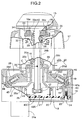
- the second cover member 21 is formed in a rectangular shape so that it fits into the opening at the other of the case main body 19 and is secured, together with a flat plate-shaped base plate 22 housed within the case main body 19, to a supporting step 23 provided on the case main body 19, by means of a plurality of screw members 24 with the base plate 22 interposed between the second cover member 21 and the supporting step 23.
- the operating shaft 16 is equipped with an operating shaft retaining member 26 so that relative movement in a confined range along the axis of the operating shaft 16 is possible but relative rotation around the axis of the operating shaft 16 is prevented, and the operating shaft retaining member 26 includes a tilt support portion 26a, which is formed so as to follow the surface of the imaginary sphere of the receiving seat 25c and is in sliding contact with the receiving seat 25c from the operating knob 15 side, a cylindrical portion 26b, which is connected to the tilt support portion 26a via a base part and coaxially surrounds the one end of the operating shaft 16, a cylindrical skirt portion 26c, which surrounds the tubular supporting portion 25b of the tilt support member 25 and is connected to the tilt support portion 26a, and four support arm portions 26d extending radially from four positions equally spaced in the peripheral direction of the skirt portion 26c.
- the operating shaft retaining member 26 includes a tilt support portion 26a, which is formed so as to follow the surface of the imaginary sphere of the receiving seat 25c and is in sliding contact with the receiving seat
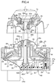
- the receiving member 44 is provided with a first guide recess 49 that comes into sliding contact with the spherical abutment portion 47a of the sliding member 47 when as shown in FIG. 8 the operating shaft 16 is tilted within a predetermined angle range from the neutral position, a second guide recess 50 that comes into sliding contact with the spherical abutment portion 47a of the sliding member 47 when as shown in FIG. 9 the operating shaft 16 is tilted beyond the predetermined angle range, and a ridge part 51 disposed between the first and second guide recesses 49 and 50; when the operating shaft 16 is tilted from the state of FIG. 8 to the state of FIG.
Landscapes
- Physics & Mathematics (AREA)
- General Physics & Mathematics (AREA)
- Engineering & Computer Science (AREA)
- Automation & Control Theory (AREA)
- Switches With Compound Operations (AREA)
- Mechanical Control Devices (AREA)
Claims (2)
- Schaltvorrichtung vom Joystick-Typ, umfassend:ein Gehäuse (18);eine Betätigungswelle (16) mit einem Betätigungsknopf (15), der an einem Ende vorgesehen ist, undein Betätigungswellen-Halteelement (26), das die Betätigungswelle (16) in Bezug auf das Gehäuse derart stützt, dass sich die Betätigungswelle (16) entlang einer Achse davon zwischen einer Rückstellposition und einer eingeschobenen Position bewegen kann und die Betätigungswelle (16) aus einer neutralen Position um einen Kipppunkt (C), der auf der Achse festgelegt ist, kippen kann, wobei es möglich ist, das Drücken der Betätigungswelle (16), die federnd in Richtung der Neutralstellung und der Rückstellposition gedrängt wird, in die eingeschobene Position zu erkennen,wobei die Betätigungswelle (16) einen Magneten (41) aufweist, der an dem anderen Ende befestigt ist, und ein dem Magneten (41) gegenüberstehender Abschnitt einer Grundplatte (22), die auf dem Gehäuse (18) montiert ist, mindestens drei Magnetelemente (43A bis 43D; 43E bis 43G) aufweist, die daran in gleichen Abständen um die Achse der Betätigungswelle (16) in der Neutralstellung fixiert sind,dadurch gekennzeichnet, dass:es möglich ist, das Verkippen der Betätigungswelle (16) aus der Neutralstellung in acht Richtungen, die in gleichen Abständen rund um die Achse festgelegt sind, zu erkennen;Klickmechanismen (45) zwischen dem Betätigungswellen-Halteelement (26) und dem Gehäuse (18) an vier Positionen bereitgestellt sind, die in gleichen Abständen rund um die Achse der Betätigungswelle (16) angeordnet sind, wobei die Klickmechanismen (45) ein Klickgefühl vermitteln, wenn die Betätigungswelle (16) aus der Neutralstellung über einen vorbestimmten Winkel hinaus verkippt wird;die Klickmechanismen (45) entsprechend zwischen dem Gehäuse und den Stützarmabschnitten (26d) des Betätigungswellen-Halteelements (26) bereitgestellt sind, wobei die Klickmechanismen jeweils an einem äußersten Ende des entsprechenden Stützarmabschnitts (26d) bereitgestellt werden; undjeder der Klickmechanismen (45) ein Gleitelement (47) in gleitendem Kontakt mit einem entsprechenden Aufnahmeelement (44) des Gehäuses (18) aufweist, wobei das Aufnahmeelement (44) ein Rippenteil (51) aufweist, das derart angeordnet ist, dass das Gleitelement (47) über das Rippenteil (51) fährt, wenn die Betätigungswelle (16) über den vorbestimmten Winkel verkippt wird.
- Schaltvorrichtung vom Joystick-Typ gemäß Anspruch 1, wobei
das Aufnahmeelement (44) an dem Gehäuse (18) an einer Seite nahe zu der Grundplatte (22), wie vom Kipppunkt (C) aus betrachtet, so ausgebildet ist, dass es dem äußersten Ende des entsprechenden Stützarmabschnitts (26d) entspricht,
jeder der Klickmechanismen (45) ferner ein mit einem Boden versehenes Stützloch (46), das an dem äußersten Ende des entsprechenden Stützarmabschnitts (26d) bereitgestellt ist, einen kugelförmigen Widerlagerabschnitt (47a), der an einem Außenende des Gleitelements (47) so ausgebildet ist, dass er gegenüber dem Aufnahmeelement (44) liegt, und eine Klickfeder (48) aufweist, welche das Gleitelement (47) in Richtung des Aufnahmeelements (44) drängt,
das Aufnahmeelement (44) mit einer ersten Führungsausnehmung (49), die gleitend mit dem kugelförmigen Widerlagerabschnitt (47a) in Kontakt ist, wenn das Betätigungswellen-Halteelement (26) in der Neutralstellung ist, einer zweiten Führungsausnehmung (50), die gleitend mit dem kugelförmigen Widerlagerabschnitt (47a) in Kontakt ist, wenn die Betätigungswelle über den vorbestimmten Winkel (16) hinaus verkippt ist, und einem Rippenteil (51) versehen ist, das zwischen den ersten und zweiten Führungsausnehmungen (49) und (50) für jedes der Gleitelemente (47) angeordnet ist, und
wenn das Betätigungswellen-Halteelement (26) aus der Neutralstellung über den vorbestimmten Winkel hinaus verkippt ist, kann der kugelförmige Widerlagerabschnitt (47a) über das Rippenteil (51) gegen die Klickfeder (48) fahren.
Applications Claiming Priority (2)
| Application Number | Priority Date | Filing Date | Title |
|---|---|---|---|
| JP2006150486A JP4921854B2 (ja) | 2006-05-30 | 2006-05-30 | ジョイスティック型スイッチ装置 |
| PCT/JP2006/323687 WO2007141894A1 (ja) | 2006-05-30 | 2006-11-28 | ジョイスティック型スイッチ装置 |
Publications (3)
| Publication Number | Publication Date |
|---|---|
| EP2023359A1 EP2023359A1 (de) | 2009-02-11 |
| EP2023359A4 EP2023359A4 (de) | 2012-05-30 |
| EP2023359B1 true EP2023359B1 (de) | 2016-02-17 |
Family
ID=38801163
Family Applications (1)
| Application Number | Title | Priority Date | Filing Date |
|---|---|---|---|
| EP06833491.1A Active EP2023359B1 (de) | 2006-05-30 | 2006-11-28 | Schaltanordnung des joystick-typs |
Country Status (5)
| Country | Link |
|---|---|
| US (1) | US8186240B2 (de) |
| EP (1) | EP2023359B1 (de) |
| JP (1) | JP4921854B2 (de) |
| CN (1) | CN101443870B (de) |
| WO (1) | WO2007141894A1 (de) |
Families Citing this family (52)
| Publication number | Priority date | Publication date | Assignee | Title |
|---|---|---|---|---|
| DE102007005253A1 (de) * | 2007-02-02 | 2008-08-07 | Deere & Company, Moline | Bedienvorrichtung für ein Fahrzeug |
| US8091678B2 (en) * | 2008-03-07 | 2012-01-10 | Deere & Company | Input control pattern |
| US20100050803A1 (en) * | 2008-09-03 | 2010-03-04 | Caterpillar Inc. | Manual control device |
| US8056432B2 (en) * | 2008-09-19 | 2011-11-15 | Honeywell International Inc. | Active control stick assembly |
| FR2942052B1 (fr) * | 2009-02-12 | 2014-08-01 | Guillemot Corp | Mini-joystick a effet hall a detection d'appui, et dispositif de controle correspondant |
| EP2218840B1 (de) | 2009-02-17 | 2012-10-10 | Kwc Ag | Sanitärarmatur mit Joysticksteuerung |
| EP2218839B1 (de) * | 2009-02-17 | 2013-06-12 | Kwc Ag | Sanitärarmatur mit einem Gelenk |
| JP5734065B2 (ja) * | 2011-04-12 | 2015-06-10 | 東洋電装株式会社 | ジョイスティック装置 |
| JP5797444B2 (ja) * | 2011-04-12 | 2015-10-21 | 東洋電装株式会社 | ジョイスティック装置 |
| JP2013083577A (ja) | 2011-10-11 | 2013-05-09 | Denso Corp | 位置検出装置 |
| CN102903551A (zh) * | 2011-12-28 | 2013-01-30 | 龙口矿业集团有限公司 | 带有隔爆型按钮开关的隔爆箱 |
| US20130293362A1 (en) | 2012-05-03 | 2013-11-07 | The Methodist Hospital Research Institute | Multi-degrees-of-freedom hand controller |
| US20150185757A1 (en) * | 2012-07-02 | 2015-07-02 | Behr-Hella Thermocontrol Gmbh | Multifunction operating device, particularly for a vehicle component |
| US9164595B2 (en) * | 2013-03-08 | 2015-10-20 | Darren C. PETERSEN | Mechanical actuator apparatus for a touchscreen |
| US9158390B2 (en) * | 2013-03-08 | 2015-10-13 | Darren C. PETERSEN | Mechanical actuator apparatus for a touch sensing surface of an electronic device |
| US20140251070A1 (en) * | 2013-03-08 | 2014-09-11 | Brenton Arthur Kornelson | Machine controller having joystick and adjustable hands-free locking mechanism |
| USD777118S1 (en) * | 2013-12-03 | 2017-01-24 | Carl Zeiss Microscopy Gmbh | Combined touchpad, operating knobs and display module for electrical control device |
| JP6336760B2 (ja) * | 2014-01-16 | 2018-06-06 | ホシデン株式会社 | 多方向入力装置 |
| CN106030439B (zh) * | 2014-12-02 | 2017-12-05 | 深圳市大疆创新科技有限公司 | 拨杆结构及采用该拨杆结构的遥控器 |
| DE102015201411A1 (de) * | 2015-01-28 | 2016-07-28 | Robert Bosch Gmbh | Motor-Pumpen-Aggregat für ein Bremssystem |
| EP3086094B1 (de) * | 2015-04-20 | 2017-10-18 | MOBA Mobile Automation AG | Handsteuergeber, steuer- und bedieneinheit mit einem handsteuergeber und arbeitsmaschine oder baumaschine |
| US11397108B2 (en) * | 2015-06-16 | 2022-07-26 | Marquardt Gmbh | Multi-function controller and method of using same |
| US10527462B2 (en) | 2016-07-08 | 2020-01-07 | Marquardt Gmbh | Encoder and method of using the same |
| US10198086B2 (en) | 2016-10-27 | 2019-02-05 | Fluidity Technologies, Inc. | Dynamically balanced, multi-degrees-of-freedom hand controller |
| CN106449257B (zh) * | 2016-10-31 | 2018-10-23 | 东莞市林积为实业投资有限公司 | 一种多向开关装置 |
| CN110087744B (zh) * | 2016-11-21 | 2020-09-29 | 雷蛇(亚太)私人有限公司 | 游戏控制器及控制游戏控制器的方法 |
| CN209859033U (zh) * | 2016-11-28 | 2019-12-27 | 阿尔卑斯阿尔派株式会社 | 操作装置 |
| US10452167B2 (en) * | 2017-05-26 | 2019-10-22 | Edward F. Larkin | Motion control device for interfacing with a computing device |
| US10048091B1 (en) * | 2017-05-30 | 2018-08-14 | Infineon Technologies Ag | Magnetic multimedia control element |
| DE102018113280B4 (de) | 2017-06-07 | 2021-01-14 | Methode Electronics Malta Ltd. | Joystick zur Dreherkennung |
| CN114674220A (zh) | 2017-10-27 | 2022-06-28 | 流体技术股份有限公司 | 用于对空指令提供触觉反馈的控制器的多轴常平架安装座 |
| CN107887194A (zh) * | 2017-12-26 | 2018-04-06 | 安徽开诚电器有限公司 | 一种防水电器开关 |
| CN108762368A (zh) * | 2018-03-27 | 2018-11-06 | 上海科世达-华阳汽车电器有限公司 | 一种控制旋钮、人机交互开关及人机交互开关的控制方法 |
| CN108733130A (zh) * | 2018-08-01 | 2018-11-02 | 上海英恒电子有限公司 | 一种多功能操作钮及其动作识别方法 |
| DE102018118839B4 (de) * | 2018-08-02 | 2020-06-18 | Behr-Hella Thermocontrol Gmbh | Dreh-/Drücksteller für eine Bedienvorrichtung in einem Fahrzeug |
| DE102018130824A1 (de) * | 2018-12-04 | 2020-06-04 | Valeo Schalter Und Sensoren Gmbh | Multimodale Eingabevorrichtung |
| CN111489908B (zh) * | 2019-01-25 | 2022-03-22 | 广东百威电子有限公司 | 一种燃气灶智能旋钮模块 |
| CN110189951B (zh) * | 2019-05-29 | 2024-05-07 | 德丰电创科技股份有限公司 | 一种操控杆 |
| WO2021038933A1 (ja) * | 2019-08-30 | 2021-03-04 | アルプスアルパイン株式会社 | 操作装置 |
| DE102019214109A1 (de) * | 2019-09-17 | 2021-03-18 | Zf Friedrichshafen Ag | Bedienvorrichtung, insbesondere für eine Vorrichtung eines Kraftfahrzeugs |
| DE102019133126A1 (de) | 2019-12-05 | 2021-06-10 | Methode Electronics Malta Ltd. | Joystick umfassend einen Hebel und ein Gehäuse |
| US11599107B2 (en) | 2019-12-09 | 2023-03-07 | Fluidity Technologies Inc. | Apparatus, methods and systems for remote or onboard control of flights |
| CN113384870B (zh) * | 2020-03-13 | 2023-11-03 | 致伸科技股份有限公司 | 摇杆模块 |
| WO2021223857A1 (de) * | 2020-05-05 | 2021-11-11 | Tekerlek Korkut | Eingabevorrichtung |
| WO2022054759A1 (ja) * | 2020-09-09 | 2022-03-17 | アルプスアルパイン株式会社 | 多方向入力装置 |
| CN115300898A (zh) * | 2021-05-05 | 2022-11-08 | 宝德科技股份有限公司 | 摇杆组件及游戏手把 |
| JP2023170969A (ja) * | 2022-05-20 | 2023-12-01 | ホシデン株式会社 | 多方向入力装置 |
| DE102021133429A1 (de) | 2021-12-16 | 2023-06-22 | Dynapac Gmbh | Bedienelement für eine Straßenbaumaschine |
| US11696633B1 (en) | 2022-04-26 | 2023-07-11 | Fluidity Technologies Inc. | System and methods for controlling motion of a target object and providing discrete, directional tactile feedback |
| US11662835B1 (en) | 2022-04-26 | 2023-05-30 | Fluidity Technologies Inc. | System and methods for controlling motion of a target object and providing discrete, directional tactile feedback |
| JP2025031116A (ja) * | 2023-08-25 | 2025-03-07 | アルプスアルパイン株式会社 | 入力装置 |
| JP2025049793A (ja) * | 2023-09-22 | 2025-04-04 | アルプスアルパイン株式会社 | 入力装置 |
Family Cites Families (11)
| Publication number | Priority date | Publication date | Assignee | Title |
|---|---|---|---|---|
| US2958233A (en) * | 1957-11-27 | 1960-11-01 | Thew Shovel Co | Valve indexing mechanism |
| US4459578A (en) * | 1983-01-13 | 1984-07-10 | Atari, Inc. | Finger control joystick utilizing Hall effect |
| EP0634037B1 (de) * | 1992-03-25 | 1996-12-27 | PENNY & GILES BLACKWOOD LIMITED | Steuerknüppel. |
| JP4233174B2 (ja) * | 1999-04-30 | 2009-03-04 | 富士通コンポーネント株式会社 | ポインティングデバイス |
| JP2002007059A (ja) * | 2000-06-27 | 2002-01-11 | Nagano Fujitsu Component Kk | 座標入力装置 |
| JP2002091697A (ja) * | 2000-09-20 | 2002-03-29 | Asahi Kasei Microsystems Kk | ポインティングデバイス |
| US6634383B2 (en) * | 2001-12-14 | 2003-10-21 | Caterpillar Inc. | Magnetic detent assist assembly |
| JP3988584B2 (ja) * | 2002-08-27 | 2007-10-10 | 松下電器産業株式会社 | 多方向入力装置 |
| JP4359478B2 (ja) * | 2003-10-14 | 2009-11-04 | アルプス電気株式会社 | ジョイスティック型スイッチ装置 |
| US7463241B2 (en) * | 2003-10-14 | 2008-12-09 | Alps Electric Co., Ltd. | Joystick input device |
| JP4063753B2 (ja) * | 2003-10-14 | 2008-03-19 | アルプス電気株式会社 | ジョイスティック型入力装置 |
-
2006
- 2006-05-30 JP JP2006150486A patent/JP4921854B2/ja active Active
- 2006-11-28 WO PCT/JP2006/323687 patent/WO2007141894A1/ja not_active Ceased
- 2006-11-28 EP EP06833491.1A patent/EP2023359B1/de active Active
- 2006-11-28 CN CN2006800546546A patent/CN101443870B/zh active Active
- 2006-11-28 US US12/298,982 patent/US8186240B2/en active Active
Also Published As
| Publication number | Publication date |
|---|---|
| CN101443870B (zh) | 2012-08-08 |
| US20090084214A1 (en) | 2009-04-02 |
| JP2007323859A (ja) | 2007-12-13 |
| EP2023359A1 (de) | 2009-02-11 |
| JP4921854B2 (ja) | 2012-04-25 |
| WO2007141894A1 (ja) | 2007-12-13 |
| CN101443870A (zh) | 2009-05-27 |
| US8186240B2 (en) | 2012-05-29 |
| EP2023359A4 (de) | 2012-05-30 |
Similar Documents
| Publication | Publication Date | Title |
|---|---|---|
| EP2023359B1 (de) | Schaltanordnung des joystick-typs | |
| US8416040B2 (en) | Joystick device | |
| JP5802111B2 (ja) | 多方向スイッチ装置 | |
| KR101698647B1 (ko) | 차량용 멀티 오퍼레이팅 스위치 유니트 | |
| KR20170051704A (ko) | 차량용 멀티 오퍼레이팅 스위치 유니트 | |
| KR20210036743A (ko) | 차량용 입력장치 | |
| US8102384B2 (en) | Interface device | |
| EP2075816B1 (de) | Schaltvorrichtung | |
| US20120286977A1 (en) | Operation input device | |
| WO2019087608A1 (ja) | 入力装置 | |
| KR101706426B1 (ko) | 차량용 멀티 오퍼레이팅 스위치 유니트 | |
| EP3059751B1 (de) | Bedienfeldvorrichtung | |
| KR101514154B1 (ko) | 차량용 멀티 오퍼레이팅 스위치 유니트 | |
| US9048046B2 (en) | Oscillation operation input device | |
| KR101435283B1 (ko) | 차량용 멀티 오퍼레이팅 스위치 유니트 | |
| JP4996548B2 (ja) | 多方向操作スイッチ装置 | |
| KR101087276B1 (ko) | 콤비네이션 스위치 | |
| EP1884858A1 (de) | Eingabevorrichtung mit Neigungssteuerung | |
| US9003913B2 (en) | Operation input device | |
| KR101481259B1 (ko) | 차량용 멀티 오퍼레이팅 스위치 유니트 | |
| JP3751522B2 (ja) | ポインティング装置 | |
| KR101141329B1 (ko) | 스위치 유니트 | |
| KR20160117792A (ko) | 차량용 멀티 펑셔널 스위치 유니트 | |
| WO2008044419A1 (en) | Operation device | |
| KR102675895B1 (ko) | 차량용 멀티 오퍼레이팅 스위치 유니트 |
Legal Events
| Date | Code | Title | Description |
|---|---|---|---|
| PUAI | Public reference made under article 153(3) epc to a published international application that has entered the european phase |
Free format text: ORIGINAL CODE: 0009012 |
|
| 17P | Request for examination filed |
Effective date: 20081121 |
|
| AK | Designated contracting states |
Kind code of ref document: A1 Designated state(s): AT BE BG CH CY CZ DE DK EE ES FI FR GB GR HU IE IS IT LI LT LU LV MC NL PL PT RO SE SI SK TR |
|
| AX | Request for extension of the european patent |
Extension state: AL BA HR MK RS |
|
| RBV | Designated contracting states (corrected) |
Designated state(s): DE FR GB IT |
|
| REG | Reference to a national code |
Ref country code: DE Ref legal event code: R079 Ref document number: 602006047982 Country of ref document: DE Free format text: PREVIOUS MAIN CLASS: H01H0025060000 Ipc: G05G0009047000 |
|
| A4 | Supplementary search report drawn up and despatched |
Effective date: 20120426 |
|
| RIC1 | Information provided on ipc code assigned before grant |
Ipc: H01H 25/06 20060101ALI20120420BHEP Ipc: G05G 9/047 20060101AFI20120420BHEP Ipc: H01H 36/00 20060101ALI20120420BHEP |
|
| DAX | Request for extension of the european patent (deleted) | ||
| GRAP | Despatch of communication of intention to grant a patent |
Free format text: ORIGINAL CODE: EPIDOSNIGR1 |
|
| INTG | Intention to grant announced |
Effective date: 20150803 |
|
| GRAS | Grant fee paid |
Free format text: ORIGINAL CODE: EPIDOSNIGR3 |
|
| GRAA | (expected) grant |
Free format text: ORIGINAL CODE: 0009210 |
|
| AK | Designated contracting states |
Kind code of ref document: B1 Designated state(s): DE FR GB IT |
|
| REG | Reference to a national code |
Ref country code: GB Ref legal event code: FG4D |
|
| REG | Reference to a national code |
Ref country code: DE Ref legal event code: R096 Ref document number: 602006047982 Country of ref document: DE |
|
| REG | Reference to a national code |
Ref country code: DE Ref legal event code: R097 Ref document number: 602006047982 Country of ref document: DE |
|
| REG | Reference to a national code |
Ref country code: FR Ref legal event code: PLFP Year of fee payment: 11 |
|
| PLBE | No opposition filed within time limit |
Free format text: ORIGINAL CODE: 0009261 |
|
| STAA | Information on the status of an ep patent application or granted ep patent |
Free format text: STATUS: NO OPPOSITION FILED WITHIN TIME LIMIT |
|
| 26N | No opposition filed |
Effective date: 20161118 |
|
| REG | Reference to a national code |
Ref country code: FR Ref legal event code: PLFP Year of fee payment: 12 |
|
| REG | Reference to a national code |
Ref country code: DE Ref legal event code: R082 Ref document number: 602006047982 Country of ref document: DE |
|
| PGFP | Annual fee paid to national office [announced via postgrant information from national office to epo] |
Ref country code: FR Payment date: 20250930 Year of fee payment: 20 |
|
| PGFP | Annual fee paid to national office [announced via postgrant information from national office to epo] |
Ref country code: DE Payment date: 20250930 Year of fee payment: 20 |
|
| PGFP | Annual fee paid to national office [announced via postgrant information from national office to epo] |
Ref country code: GB Payment date: 20251001 Year of fee payment: 20 |
|
| PGFP | Annual fee paid to national office [announced via postgrant information from national office to epo] |
Ref country code: IT Payment date: 20251022 Year of fee payment: 20 |