EP2022900A2 - Sanitärarmatur - Google Patents
Sanitärarmatur Download PDFInfo
- Publication number
- EP2022900A2 EP2022900A2 EP20080012272 EP08012272A EP2022900A2 EP 2022900 A2 EP2022900 A2 EP 2022900A2 EP 20080012272 EP20080012272 EP 20080012272 EP 08012272 A EP08012272 A EP 08012272A EP 2022900 A2 EP2022900 A2 EP 2022900A2
- Authority
- EP
- European Patent Office
- Prior art keywords
- water
- housing
- sanitary fitting
- cold
- supply module
- Prior art date
- Legal status (The legal status is an assumption and is not a legal conclusion. Google has not performed a legal analysis and makes no representation as to the accuracy of the status listed.)
- Granted
Links
- XLYOFNOQVPJJNP-UHFFFAOYSA-N water Substances O XLYOFNOQVPJJNP-UHFFFAOYSA-N 0.000 claims abstract description 151
- 238000004519 manufacturing process Methods 0.000 claims abstract description 10
- 238000000034 method Methods 0.000 claims abstract description 7
- 239000002184 metal Substances 0.000 claims abstract description 3
- 239000002131 composite material Substances 0.000 claims description 3
- 238000011900 installation process Methods 0.000 claims description 2
- 238000005266 casting Methods 0.000 description 7
- 239000000463 material Substances 0.000 description 3
- 239000004576 sand Substances 0.000 description 3
- 238000007789 sealing Methods 0.000 description 3
- 230000001419 dependent effect Effects 0.000 description 2
- 239000000565 sealant Substances 0.000 description 2
- 239000011230 binding agent Substances 0.000 description 1
- 238000005253 cladding Methods 0.000 description 1
- 238000004140 cleaning Methods 0.000 description 1
- 238000010276 construction Methods 0.000 description 1
- 238000011109 contamination Methods 0.000 description 1
- 230000007423 decrease Effects 0.000 description 1
- 230000007547 defect Effects 0.000 description 1
- 230000000694 effects Effects 0.000 description 1
- 230000002349 favourable effect Effects 0.000 description 1
- 239000012530 fluid Substances 0.000 description 1
- 238000003780 insertion Methods 0.000 description 1
- 230000037431 insertion Effects 0.000 description 1
- 238000009434 installation Methods 0.000 description 1
- 239000007769 metal material Substances 0.000 description 1
- 239000003110 molding sand Substances 0.000 description 1
- 238000000465 moulding Methods 0.000 description 1
- 238000007493 shaping process Methods 0.000 description 1
- 230000007704 transition Effects 0.000 description 1
Images


Classifications
-
- E—FIXED CONSTRUCTIONS
- E03—WATER SUPPLY; SEWERAGE
- E03C—DOMESTIC PLUMBING INSTALLATIONS FOR FRESH WATER OR WASTE WATER; SINKS
- E03C1/00—Domestic plumbing installations for fresh water or waste water; Sinks
- E03C1/02—Plumbing installations for fresh water
- E03C1/04—Water-basin installations specially adapted to wash-basins or baths
-
- Y—GENERAL TAGGING OF NEW TECHNOLOGICAL DEVELOPMENTS; GENERAL TAGGING OF CROSS-SECTIONAL TECHNOLOGIES SPANNING OVER SEVERAL SECTIONS OF THE IPC; TECHNICAL SUBJECTS COVERED BY FORMER USPC CROSS-REFERENCE ART COLLECTIONS [XRACs] AND DIGESTS
- Y10—TECHNICAL SUBJECTS COVERED BY FORMER USPC
- Y10T—TECHNICAL SUBJECTS COVERED BY FORMER US CLASSIFICATION
- Y10T137/00—Fluid handling
- Y10T137/8593—Systems
- Y10T137/87571—Multiple inlet with single outlet
- Y10T137/87652—With means to promote mixing or combining of plural fluids
-
- Y—GENERAL TAGGING OF NEW TECHNOLOGICAL DEVELOPMENTS; GENERAL TAGGING OF CROSS-SECTIONAL TECHNOLOGIES SPANNING OVER SEVERAL SECTIONS OF THE IPC; TECHNICAL SUBJECTS COVERED BY FORMER USPC CROSS-REFERENCE ART COLLECTIONS [XRACs] AND DIGESTS
- Y10—TECHNICAL SUBJECTS COVERED BY FORMER USPC
- Y10T—TECHNICAL SUBJECTS COVERED BY FORMER US CLASSIFICATION
- Y10T29/00—Metal working
- Y10T29/49—Method of mechanical manufacture
- Y10T29/49826—Assembling or joining
Definitions
- the present invention relates to sanitary fittings according to the preamble of patent claim 1 and a method for the production of sanitary fittings according to claim 13.
- Manufacturing process for sanitary fittings are known. Often they are formed as castings in permanent molds, as they can be realized in a simple manner with complicated shapes. To guide the fluid within the cast housing, it is known to introduce channels that require complicated Gellokernformen depending on the number and arrangement of the desired guides.
- molding sand mixed with binding agent is pressed into a core mold with a certain shot pressure and temperature in a core shooting machine. After curing of the casting core thus produced, it is installed in the casting mold. Following the casting, the sand is removed through openings placed in the casting. Depending on the guidance of the waterways in the fittings, castings with high weight and high material consumption are produced.
- thermocouples or mixing cartridges In order to save weight, it is known to produce water ducts separately from valve body housings, to connect these with the components that contain functional components of the valve such as thermocouples or mixing cartridges and then to provide them with a housing shell.
- a thermostatic valve which consists of two connection blocks, one block the valve top and the hot water inlet and the other block the thermostatic element and the Cold water inlet contains. The two blocks are connected by water pipes and surrounded by an outer shell.
- fittings consist of many items, so that the assembly costs significantly increased.
- the object of the invention is to provide a sanitary fitting with low installation costs, in which the water supply can be made separately from a housing.
- a sanitary fitting comprising a housing and a water supply module, wherein the housing has connections for a cold and a hot water supply and an outlet for mixed water, and the water supply module comprises a preformed hollow profile and at least one inlet for cold, hot or mixed water, provided in which the housing is in one piece and the water supply module is sealingly connectable to the housing. Furthermore, the water supply module may also each include an inlet for cold and hot water.
- the housing has, in addition to the openings for the water connections and the water outlet on another opening for insertion of the water supply module.
- the water guide module can thus be inserted from one side into the housing and positively or non-positively connected with this using sealants. This type of manufacturing gives the utmost freedom in choosing the materials for housing and water supply module, since the fitting can be made so that the water does not come into contact with the housing.
- the receptacles for a functional component in particular a thermostatic element, a mixing cartridge or a valve top are provided in the water supply module and not in the housing. This simplifies the effort in producing the housing's interior.
- a further advantageous embodiment provides that the water supply module comprises two separate water paths, wherein the one waterway surrounds the other at least partially radially. As a result, a very space-saving design can be achieved.
- the water supply module for example, the mixed water guide
- the water supply module consists of a tube and inlet and outlet are respectively provided at the pipe end.
- the water supply module is equipped with O-rings and inserted into the receptacles provided in the housing. The fixation takes place via the frictional engagement of the sealant.
- the inlets for cold and hot water are provided on the water supply module in the radial direction.
- the water guide module or the hollow profile is formed so that tight transitions to the connections for cold and hot water can be achieved.
- the tubes or cylindrical hollow profiles, which make up the water supply module flattened in this area and provided for example with a groove for an O-ring.
- the inlet for hot water on the water supply module is sealingly connected to the connection for the hot water supply to the housing.
- the cold water enters the housing at the connection for cold water and flows around the water supply and the housing interior.
- a so-called "cool-touch" effect is achieved, since the waterways that carry hot or warm water are not connected to the surface of the fitting, but are surrounded by cold water. Scalding the user by touching while showering or cleaning the valve are excluded.
- the one-piece design of the housing is of great advantage, since the sealing points are reduced to the connections and the outlet.
- the inlets for cold and hot water on the water supply module are arranged in the region of the receptacle for a thermostatic element. This means that the thermostat is located on the side of the hot water connection and the hot water is led directly from the housing connection into the thermostat area. The cold water flows around the inside of the housing and the water supply from the outside until it reaches the inlet in the thermostat area.
- the water supply module is formed so that both the housing connection for cold water with an inlet for cold water at the water supply module and the housing connection for hot water with an inlet to the water supply module is sealingly connected.
- the design of the water supply module further allows the outlets to be positioned at different locations so that they correspond to the mixed water outlet on the housing. This is in each case dependent on whether the mixed water, whose amount is controlled by a valve top, is guided in the inner or outer waterway. Accordingly, the outlet of the water supply module is only on the outside Waterway or at the inner waterway connected to the mixed water outlet of the housing.
- Both plastic and metal materials can be used for the housing and / or the water-guiding module.
- a large number of methods are currently available for shaping the hollow profiles for the water guidance module.
- Especially for the production of the areas for receiving the functional components are offered in hollow profiles made of metal processes such as "heat forming", since in this case thin wall thicknesses and thus a lightweight and material-saving construction can be achieved.
- the invention provides a method for the production of sanitary fittings, in which initially a one-piece housing for a sanitary fitting with connections for a cold and a hot water inlet and a mixed water outlet and a water supply module are made separately, the order is not important. Subsequently, the water supply module is inserted into the housing in such a way that during the installation process of the water supply module in the region of a connection point and in the area of the mixed water outlet, a dense composite of housing and water supply module is formed. This composite can be achieved for example by positive or non-positive connections between the housing and water supply module, each suitable sealing means are used at the connection points.
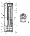
- Fig. 1 shows a section through a sanitary fitting 1 according to the invention, in this case a thermostatic mixer.
- the sanitary fitting 1 has a housing 2, which consists of a cast body. This is largely cylindrical and has except the necessary openings on the jacket for hot water connection 21, cold water connection 22 and outlet 4 on the sides each have an opening 23 for a thermostatic element and an opening 24 for a shut-off valve.
- nozzles 25, 26 are integrally formed in the cast body, which have the necessary connection geometries.
- the passage opening tapers so that it corresponds to an inlet 34, 35 on the water supply module 3 and allows a tight connection to this.
- the water guide module 3 consists in the present case of a two-part hollow body, the first part of which is inserted through the housing opening 23 for the thermostat and the second part through the housing opening 24 for the shut-off valve in the housing 2.
- the water supply module 3 is divided into several areas.
- a receptacle 6 for a thermostatic element the geometry of which corresponds to the dimensions of the thermostatic element, is followed by a cylindrical tube 33 for guiding the mixed water, which in turn ends at the inlet 51 of a receptacle for a shut-off valve 5.
- the outlets 52 of the receptacle 5 are in turn connected to a second tube 32 which radially surrounds the first cylindrical tube 33 up to the housing outlet 4.
- the cylindrical tube 33 for the first mixing water path is integrally connected to the receptacle 6 for the thermostatic element.
- the jacket thickness of the cylindrical tube 33 decreases abruptly in the region of the housing outlet 4 and runs constantly up to the tube end.
- the second part of the water guide module 3 has a substantially cylindrical shape. This is pushed from the other side of the valve 1 as a sleeve on the cylindrical tube 33 of the first mixing water path and frictionally connected in the region of the tube with the larger cladding thickness via a sealing means with this.
- the hot water connection 21 of the housing 2 opens directly into the hot water inlet 35 of the water supply module 3, while the cold water connection 22 initially only leads into the housing interior.
- the cold water flows around the water guide module 3 until it reaches the cold water inlet 34 on the water guide module 3, which is like the hot water inlet 35 to the receptacle 6 for the thermostatic element.
- the mixed water leaves the receptacle 6 for the thermostatic element, passes through the first mixing water 33 to the shut-off valve, through the outlets on the receptacle 5 for the shut-off valve to the second mixing water path 32, which radially surrounds the first and flows from there to outlet 4, which in the center of the fitting 1 is located at the bottom.
- FIG. 2 extends the second outer waterway 32 to the receptacle 6 for the thermostatic element and is connected there with this, so that the water supply module 3 is present as a unit in one-piece form.
- the dimensions of the water guide module 3 are chosen so that it can be pushed and mounted from one side of the housing 1 in this.
- the water supply in the water supply module 3 is changed.
- the inlet for the hot water 35 is provided on the outer waterway 31, which thus acts as a hot water path.
- the hot water reaches the inlet for hot water 35 at the receptacle 6 for the thermostatic element.
- the cold water connection 22 of the housing 1 opens directly to the receptacle 6 for the thermostatic element and is connected there directly to the inlet for cold water 34.
- the mixed water passes through the inner waterway 33 to receive 5 for the shut-off valve and leaves the housing 1 through the outlet 4 which is provided in the region of the receptacle 5 for the shut-off valve. Since the waterways for cold and hot water do not intersect in this embodiment, the length of the fitting 1 can be shortened, resulting in a further material savings.
Abstract
Description
- Die vorliegende Erfindung betrifft Sanitärarmaturen gemäß dem Oberbegriff des Patentanspruchs 1 und ein Verfahren zur Herstellung von Sanitärarmaturen gemäß Patentanspruch 13.
- Herstellverfahren für Sanitärarmaturen sind bekannt. Oftmals werden sie als Gussteile in Dauerformen ausgebildet, da sich diese in einfacher Weise auch mit komplizierten Formgebungen realisieren lassen. Zur Führung des Fluids innerhalb der Gussgehäuse ist es bekannt, Kanäle einzubringen, die je nach Anzahl und Anordnung der gewünschten Führungen komplizierte Gießkernformen erfordern. Zur Herstellung von Gießkernen wird in einer Kernschießmaschine mit Bindemittel versetzter Formsand mit einem bestimmten Schussdruck und -temperatur in eine Kernform gepresst. Nach dem Aushärten des so hergestellten Gusskerns wird dieser in die Gießform eingebaut. Im Anschluss an den erfolgten Abguss wird der Sand durch im Gussstück platzierte Öffnungen entfernt. Je nach Führung der Wasserwege in den Armaturen entstehen Gussteile mit hohem Gewicht und hohem Materialverbrauch.
- Um Gewicht einzusparen ist es bekannt, Wasserführungen getrennt von Armaturengehäusen herzustellen, diese mit den Bauteilen, die Funktionsbauteile der Armatur wie Thermoelemente oder Mischkartuschen enthalten zu verbinden und anschließend mit einer Gehäusehülle zu versehen. Aus der
EP 0 797 136 A1 ist eine Thermostatarmatur bekannt, die aus zwei Anschlussblöcken besteht, wobei der eine Block das Ventiloberteil und den Heißwasserzulauf und der andere Block das Thermostatelement und den Kaltwasserzulauf enthält. Die beiden Blöcke sind durch Wasserführungsrohre miteinander verbunden und von einer äußeren Schale umhüllt.
Derartige Armaturen bestehen jedoch aus vielen Einzelteilen, so dass sich der Montageaufwand erheblich vergrößert. - Vor diesem Hintergrund besteht die Aufgabe der Erfindung darin, eine Sanitärarmatur mit geringem Montageaufwand zu schaffen, bei der die Wasserführung getrennt von einem Gehäuse hergestellt werden kann.
- Diese Aufgabe wird erfindungsgemäß durch eine Sanitärarmatur mit den Merkmalen des Patentanspruchs 1 und durch ein Verfahren zur Herstellung einer Sanitärarmatur gemäß Patentanspruch 13 gelöst. Günstige Ausgestaltungsformen sind Gegenstand von Unteransprüchen.
- Dazu wird eine Sanitärarmatur, die ein Gehäuse sowie ein Wasserführungsmodul umfasst, wobei das Gehäuse Anschlüsse für einen Kalt- und einen Heißwasserzulauf und einen Auslass für Mischwasser aufweist, und das Wasserführungsmodul ein vorgeformtes Hohlprofil umfasst und wenigstens einen Einlass für Kalt-, Heiß oder Mischwasser, bereitgestellt, bei der das Gehäuse einteilig und das Wasserführungsmodul dichtend mit dem Gehäuse verbindbar ist. Weiterhin kann das Wasserführungsmodul auch je einen Einlass für Kalt und Heißwasser umfassen. Der Vorteil einer derartigen Sanitärarmatur mit einem einteiligen Gehäuse und einer von diesem getrennt hergestellten Wasserführung besteht darin, dass bei einem Gussgehäuse die Komplexität der Sandkernherstellung und des Gießprozesses stark reduziert wird, da nur noch eine Kammer mit den notwendigen Öffnungen hergestellt werden muss. Dadurch vereinfacht sich auch das Entsanden der Armatur, wodurch die Verschleppung des Sandes in nachfolgende Prozesse reduziert wird. Hierdurch werden Werkzeugverschleiß durch Sandkörner bei der mechanischen Bearbeitung, Oberflächenfehler und starke Verschmutzungen im Galvanikbecken weitgehend vermieden.
- Das Gehäuse weist neben den Öffnungen für die Wasseranschlüsse und den Wasserauslass eine weitere Öffnung zum Einführen des Wasserführungsmoduls auf. Das Wasserführungsmodul kann somit von einer Seite in das Gehäuse eingeschoben und form- oder kraftschlüssig mit diesem unter Verwendung von Dichtmitteln verbunden werden. Diese Art der Herstellung gewährt die größtmögliche Freiheit bei der Auswahl der Materialien für Gehäuse und Wasserführungsmodul, da die Armatur so hergestellt werden kann, dass das Wasser nicht mit dem Gehäuse in Berührung kommt.
- Gemäß einer Ausgestaltung der Erfindung sind die Aufnahmen für ein Funktionsbauteil, insbesondere ein Thermostatelement, eine Mischkartusche oder ein Ventiloberteil im Wasserführungsmodul und nicht im Gehäuse vorgesehen. Dies vereinfacht den Aufwand beim Herstellen der Gehäuseinnenform.
- Eine weitere vorteilhafte Weiterbildung sieht vor, dass das Wasserführungsmodul zwei getrennte Wasserwege umfasst, wobei der eine Wasserweg den anderen wenigstens teilweise radial umgibt. Hierdurch kann eine sehr Platz sparende Bauweise erzielt werden.
- Eine vorteilhafte Ausgestaltung sieht vor, dass das Wasserführungsmodul, beispielsweise die Mischwasserführung, aus einem Rohr besteht und Ein- und Auslass jeweils am Rohrende vorgesehen sind. Das Wasserführungsmodul wird mit O-Ringen versehen und in dafür vorgesehene Aufnahmen im Gehäuse eingeschoben. Die Fixierung erfolgt über den Reibschluss der Dichtmitttel.
Gemäß einer Weiterbildung der Erfindung sind die Einlässe für Kalt- und Heißwasser am Wasserführungsmodul in radialer Richtung vorgesehen. Dabei ist das Wasserführungsmodul bzw. das Hohlprofil so ausgeformt, dass dichte Übergänge zu den Anschlüssen für Kalt- und Heißwasser erzielt werden. Hierzu sind die Rohre oder zylindrischen Hohlprofile, aus denen das Wasserführungsmodul besteht, in diesem Bereich abgeflacht und beispielsweise mit einer Nut für einen O-Ring versehen. - Bei einer Ausgestaltung der Sanitärarmatur ist ausschließlich der Einlass für Heißwasser am Wasserführungsmodul dichtend mit dem Anschluss für den Heißwasserzulauf am Gehäuse verbindbar. Dies bedeutet, dass das Kaltwasser am Anschluss für Kaltwasser in das Gehäuse gelangt und die Wasserführung und den Gehäuseinnenraum umströmt. Somit wird ein sogenannter "Cool-touch"-Effekt erzielt, da die Wasserwege, die heißes oder warmes Wasser führen, nicht mit der Oberfläche der Armatur in Verbindung stehen, sondern von kaltem Wasser umgeben sind. Verbrühungen des Nutzers durch Berühren beim Duschen oder Reinigen der Armatur sind damit ausgeschlossen. Hierbei ist die Einteiligkeit des Gehäuses von großem Vorteil, da die Dichtstellen auf die Anschlüsse und den Auslass reduziert werden. Die Einlässe für Kalt- und Heißwasser am Wasserführungsmodul sind dabei im Bereich der Aufnahme für ein Thermostatelement angeordnet. Dies bedeutet, dass der Thermostat auf der Seite des Heißwasseranschlusses angeordnet ist und das Heißwasser direkt vom Gehäuseanschluss in den Thermostatbereich geführt wird. Das Kaltwasser umspült das Gehäuseinnere und die Wasserführung von außen bis es an den Einlass im Thermostatbereich in die Wasserführung gelangt.
- Bei einer weiteren Ausgestaltung ist das Wasserführungsmodul so ausgeformt, dass sowohl der Gehäuseanschluss für Kaltwasser mit einem Einlass für Kaltwasser am Wasserführungsmodul als auch der Gehäuseanschluss für Heißwasser mit einem Einlass am Wasserführungsmodul dichtend verbindbar ist.
- Die Bauweise des Wasserführungsmoduls ermöglicht weiterhin, die Auslässe an unterschiedlichen Stellen zu positionieren, so dass sie mit dem Mischwasserauslass am Gehäuse korrespondieren. Dies ist jeweils davon abhängig, ob das Mischwasser, dessen Menge über ein Ventiloberteil gesteuert wird, im inneren oder äußeren Wasserweg geführt wird. Dementsprechend ist der Auslass des Wasserführungsmoduls nur am äußeren Wasserweg oder am inneren Wasserweg mit dem Mischwasserauslass des Gehäuses verbunden.
- Für das Gehäuse und/oder das Wasserführungsmodul sind sowohl Materialien aus Kunststoff als auch aus Metall verwendbar. Dadurch bieten sich gerade zur Formgebung der Hohlprofile für das Wasserführungsmodul eine Vielzahl von Verfahren an. Gerade zur Herstellung der Bereiche für die Aufnahme der Funktionsbauteile bieten sich bei Hohlprofilen aus Metall Verfahren wie "Heatforming" an, da hierbei dünne Wandstärken und somit eine leichte und Material sparende Konstruktion erzielt werden kann.
- Somit wird durch die Erfindung ein Verfahren zur Herstellung von Sanitärarmaturen bereitgestellt, bei dem zunächst ein einteiliges Gehäuses für eine Sanitärarmatur mit Anschlüssen für einen Kalt- und einen Warmwasserzulauf und einem Mischwasserauslass sowie ein Wasserführungsmodul getrennt voneinander gefertigt werden, wobei die Reihenfolge nicht von Belang ist. Anschließend wird das Wasserführungsmodul derart in das Gehäuse eingelegt, dass beim Einbauvorgang des Wasserführungsmoduls im Bereich einer Anschlussstelle und im Bereich des Mischwasserauslasses ein dichter Verbund von Gehäuse und Wasserführungsmodul entsteht. Dieser Verbund kann beispielsweise durch formschlüssige oder kraftschlüssige Verbindungen zwischen Gehäuse und Wasserführungsmodul erzielt werden, wobei jeweils geeignete Dichtmittel an den Verbindungsstellen zum Einsatz kommen.
- Anhand der Figuren soll die Erfindung näher beschrieben werden. Es zeigen
- Fig. 1
- einen Schnitt durch ein erstes Ausführungsbeispiel für eine erfindungsgemäße Sanitärarmatur
- Fig. 2
- einen Schnitt durch ein zweites Ausführungsbeispiel
- Fig. 3
- einen Schnitt durch ein drittes Ausführungsbeispiel.
-
Fig. 1 zeigt einen Schnitt durch eine erfindungsgemäße Sanitärarmatur 1, im vorliegenden Fall eine Thermostatbatterie. Die Sanitärarmatur 1 weist ein Gehäuse 2 auf, das aus einem Gusskörper besteht. Dieses ist weitgehend zylinderförmig und weist außer den notwendigen Öffnungen am Mantel für Heißwasseranschluss 21, Kaltwasseranschluss 22 und Auslauf 4 an den Seiten je eine Öffnung 23 für ein Thermostatelement und eine Öffnung 24 für ein Absperrventil auf. An den Öffnungen für den Heiß- und Kaltwasseranschluss 21, 22 sind im Gusskörper 2 Stutzen 25, 26 angeformt, die die notwendigen Anschlussgeometrien aufweisen. Im unteren Bereich des Stutzen 25, 26 verjüngt sich die Durchlassöffnung, so dass diese mit einem Einlass 34, 35 am Wasserführungsmodul 3 korrespondiert und eine dichte Verbindung zu diesem ermöglicht. Das Wasserführungsmodul 3 besteht im vorliegenden Fall aus einem zweiteiligen Hohlkörper, dessen erster Teil durch die Gehäuseöffnung 23 für den Thermostaten und dessen zweiter Teil durch die Gehäuseöffnung 24 für das Absperrventil in das Gehäuse 2 eingeschoben wird. Das Wasserführungsmodul 3 untergliedert sich dabei in mehrere Bereiche. An eine Aufnahme 6 für ein Thermostatelement, deren Geometrie den Abmessungen des Thermostatelements entspricht, schließt sich ein zylindrisches Rohr 33 zur Führung des Mischwassers an, das wiederum am Einlass 51 einer Aufnahme für ein Absperrventil 5 endet. Die Auslässe 52 der Aufnahme 5 stehen wiederum in Verbindung mit einem zweiten Rohr 32, das das erste zylindrische Rohr 33 bis zum Gehäuseauslass 4 radial umgibt. Das zylindrische Rohr 33 für den ersten Mischwasserweg ist einstückig mit der Aufnahme 6 für das Thermostatelement verbunden. Die Manteldicke des zylindrischen Rohrs 33 nimmt im Bereich des Gehäuseauslasses 4 sprungartig ab und verläuft bis zum Rohrende konstant. Der zweite Teil des Wasserführungsmoduls 3 weist eine im Wesentlichen zylindrische Form auf. Dieser wird von der anderen Seite der Armatur 1 wie eine Hülse auf das zylindrische Rohr 33 des ersten Mischwasserweges aufgeschoben und im Bereich des Rohres mit der größeren Manteldicke über ein Dichtmittel reibschlüssig mit diesem verbunden. - Der Heißwasseranschluss 21 des Gehäuses 2 mündet direkt in den Heißwassereinlass 35 des Wasserführungsmoduls 3, während der Kaltwasseranschluss 22 zunächst nur in das Gehäuseinnere führt. Das Kaltwasser umströmt das Wasserführungsmodul 3 bis es zu dem Kaltwassereinlass 34 am Wasserführungsmodul 3 gelangt, der sich wie der Heißwassereinlass 35 an der Aufnahme 6 für das Thermostatelement befindet. Das Mischwasser verlässt die Aufnahme 6 für das Thermostatelement, gelangt durch den ersten Mischwasserweg 33 zum Absperrventil, durch die Auslässe an der Aufnahme 5 für das Absperrventil zum zweiten Mischwasserweg 32, der den ersten radial umgibt und fließt von dort um Auslass 4, der sich in der Mitte der Armatur 1 an deren Unterseite befindet.
- Im Ausführungsbeispiel der
Figur 2 verläuft der zweite äußere Wasserweg 32 bis zur Aufnahme 6 für das Thermostatelement und ist dort mit dieser verbunden, so dass das Wasserführungsmodul 3 als Baueinheit in einteiliger Form vorliegt. Die Abmessungen des Wasserführungsmoduls 3 sind dabei so gewählt, dass dieses von einer Seite des Gehäuses 1 in dieses hinein geschoben und montiert werden kann. - Bei dem Ausführungsbeispiel der
Figur 3 ist die Wasserführung im Wasserführungsmodul 3 geändert. Dazu ist der Einlass für das Heißwasser 35 am äußeren Wasserweg 31 vorgesehen, der somit als Heißwasserweg fungiert. Hierdurch gelangt das Heißwasser zu dem Einlass für Heißwasser 35 an der Aufnahme 6 für das Thermostatelement. Im vorliegenden Fall mündet der Kaltwasseranschluss 22 des Gehäuses 1 direkt an der Aufnahme 6 für das Thermostatelement und ist dort direkt mit dem Einlass für Kaltwasser 34 verbunden. Das Mischwasser gelangt durch den inneren Wasserweg 33 zur Aufnahme 5 für das Absperrventil und verlässt das Gehäuse 1 durch den Auslauf 4 der im Bereich der Aufnahme 5 für das Absperrventil vorgesehen ist. Da sich die Wasserwege für Kalt- und Heißwasser bei dieser Ausgestaltung nicht kreuzen, kann die Länge der Armatur 1 verkürzt werden, woraus eine weitere Materialersparnis resultiert. -
- 1
- Sanitärarmatur hier Thermostatarmatur
- 2
- Gehäuse
- 21
- Anschlussformteil Heißwasseranschluss
- 22
- Anschlussformteil Kaltwasseranschluss
- 3
- Wasserführungsmodul
- 32
- äußerer Wasserweg
- 33
- innerer Wasserweg
- 34
- Einlass Kaltwasser
- 35
- Einlass Heißwasser
- 36
- Auslass Wasserführungsmodul
- 4
- Auslass Gehäuse
- 5
- Aufnahme für Oberteil
- 51
- Einlass
- 52
- Auslass
- 6
- Aufnahme für Thermostatelement
Claims (14)
- Sanitärarmatur (1) im Wesentlichen umfassend- ein Gehäuse (2),- - das Anschlüsse (21, 22) für einen Kalt- und einen Heißwasserzulauf und- - einen Auslass (4) für Mischwasser aufweistsowie- ein Wasserführungsmodul (3), das ein vorgeformtes Hohlprofil mit wenigstens einem Einlass (34, 35) für Kalt-, Heiß- oder Mischwasser umfasst,dadurch gekennzeichnet, dass das Gehäuse (2) einteilig und das Wasserführungsmodul (3) dichtend mit dem Gehäuse (2) verbindbar ist.
- Sanitärarmatur (1) gemäß Anspruch 2, dadurch gekennzeichnet, dass das Wasserführungsmodul (3) je einen Einlass (34, 35) für Kalt- und Heißwasser umfasst.
- Sanitärarmatur (1) gemäß Anspruch 2, dadurch gekennzeichnet, dass das Wasserführungsmodul (3) eine Aufnahme (5, 6) für ein Funktionsbauteil, insbesondere ein Thermostatelement, eine Mischkartusche oder ein Ventiloberteil aufweist.
- Sanitärarmatur (1) gemäß Anspruch 1 oder 2, dadurch gekennzeichnet, dass das Wasserführungsmodul (3) zwei getrennte Wasserwege (32, 33) umfasst, wobei der eine Wasserweg (32) den anderen (33) wenigstens teilweise radial umgibt.
- Sanitärarmatur (1) gemäß einem der vorhergehenden Ansprüche, dadurch gekennzeichnet, dass die Einlässe (34, 35) für Kalt- und Heißwasser am Wasserführungsmodul (3) in radialer Richtung vorgesehen sind.
- Sanitärarmatur (1) gemäß einem der vorhergehenden Ansprüche, dadurch gekennzeichnet, dass der Einlass (35) für Heißwasser am Wasserführungsmodul (3) dichtend mit dem Anschluss für den Heißwasserzulauf (21) am Gehäuse (2) verbindbar ist und das Kaltwasser am Anschluss für Kaltwasser (22) in das Gehäuse (2) gelangt und die Wasserführung und den Gehäuseinnenraum umströmt.
- Sanitärarmatur (1) gemäß einem der Ansprüche 2 bis 5, dadurch gekennzeichnet, dass die Einlässe (34, 35) für Kalt- und Heißwasser im Bereich der Aufnahme (6) für ein Thermostatelement am Wasserführungsmodul (3) vorgesehen sind.
- Sanitärarmatur (1) gemäß einem der Ansprüche 1 bis 4, dadurch gekennzeichnet, dass die Einlässe (34, 35) für Kalt- und Heißwasser am Wasserführungsmodul (3) dichtend mit den Anschlüssen (21, 22) für Kalt- und Heißwasser am Gehäuse (2) verbindbar sind.
- Sanitärarmatur (1) gemäß einem der vorhergehenden Ansprüche, dadurch gekennzeichnet, dass am Wasserführungsmodul (3) ein Auslass für Mischwasser vorgesehen ist, der mit dem Mischwasserauslass (4) des Gehäuses korrespondiert.
- Sanitärarmatur (1) gemäß Anspruch 8, dadurch gekennzeichnet, dass der Auslass für Mischwasser am Wasserführungsmodul (3) den äußeren Wasserweg (32) mit dem Mischwasserauslass (4) des Gehäuses verbindet.
- Sanitärarmatur (1) gemäß Anspruch 8, dadurch gekennzeichnet, dass der Auslass für Mischwasser am Wasserführungsmodul (3) den inneren Wasserweg (33) mit dem Mischwasserauslass (4) des Gehäuses verbindet.
- Sanitärarmatur (1) gemäß einem der vorhergehenden Ansprüche, dadurch gekennzeichnet, dass die Aufnahme (6) für die Funktionselemente aus einem vorgeformten Hohlprofil vorgesehen ist.
- Sanitärarmatur (1) gemäß einem der vorhergehenden Ansprüche, dadurch gekennzeichnet, dass das Gehäuse (2) und/oder die vorgeformten Hohlprofile aus Kunststoff oder Metall vorgesehen sind.
- Verfahren zur Herstellung von Sanitärarmaturen mit den Schritten- Herstellen eines einteiligen Gehäuses (2) für eine Sanitärarmatur mit Anschlüssen (21, 22) für einen Kalt- und einen Heißwasserzulauf und einem Mischwasserauslass (4),- Herstellen eines Wasserführungsmoduls (3)- Einlegen des Wasserführungsmoduls (3) in das Gehäuse (2), derart, dass beim Einbauvorgang des Wasserführungsmoduls (3) im Bereich einer Anschlussstelle und im Bereich des Mischwasserauslasses (4) ein dichter Verbund von Gehäuse (2) und Wasserführungsmodul (3) entsteht.
Priority Applications (2)
| Application Number | Priority Date | Filing Date | Title |
|---|---|---|---|
| DE200810033083 DE102008033083A1 (de) | 2007-08-08 | 2008-07-15 | Sanitärarmatur |
| US12/188,682 US20090038700A1 (en) | 2007-08-08 | 2008-08-08 | Plumbing fixture |
Applications Claiming Priority (1)
| Application Number | Priority Date | Filing Date | Title |
|---|---|---|---|
| DE102007037395 | 2007-08-08 |
Publications (3)
| Publication Number | Publication Date |
|---|---|
| EP2022900A2 true EP2022900A2 (de) | 2009-02-11 |
| EP2022900A3 EP2022900A3 (de) | 2012-10-03 |
| EP2022900B1 EP2022900B1 (de) | 2017-05-31 |
Family
ID=39708759
Family Applications (1)
| Application Number | Title | Priority Date | Filing Date |
|---|---|---|---|
| EP08012272.4A Active EP2022900B1 (de) | 2007-08-08 | 2008-07-08 | Sanitärarmatur |
Country Status (3)
| Country | Link |
|---|---|
| US (1) | US20090038700A1 (de) |
| EP (1) | EP2022900B1 (de) |
| DE (1) | DE102008033083A1 (de) |
Cited By (2)
| Publication number | Priority date | Publication date | Assignee | Title |
|---|---|---|---|---|
| EP2551413A1 (de) * | 2011-07-28 | 2013-01-30 | Caspro, S.A. | Thermostatventil |
| EP2390427A3 (de) * | 2010-05-26 | 2014-07-30 | Hansa Metallwerke AG | Sanitäre Mischarmatur zur Montage an einer Gebäudewand |
Families Citing this family (3)
| Publication number | Priority date | Publication date | Assignee | Title |
|---|---|---|---|---|
| ES2394583B1 (es) | 2010-05-13 | 2013-12-12 | Roca Sanitario, S.A | Grifo termostatico |
| US10921832B2 (en) * | 2016-05-27 | 2021-02-16 | Zurn Industries, Llc | Hot water valve with integral thermostatic mixing cartridge |
| DE102020116977A1 (de) * | 2020-06-26 | 2021-12-30 | Grohe Ag | Thermostatmischarmatur und Verfahren zur deren Herstellung |
Citations (2)
| Publication number | Priority date | Publication date | Assignee | Title |
|---|---|---|---|---|
| EP0797136A1 (de) | 1996-03-22 | 1997-09-24 | Zipponi Rubinetterie S.n.c. di Nember Oscar & C. | Thermostatische Mischarmatur für Sanitäranlagen |
| DE10346999A1 (de) | 2003-10-07 | 2005-05-04 | Grohe Water Tech Ag & Co Kg | Mischbatterie |
Family Cites Families (7)
| Publication number | Priority date | Publication date | Assignee | Title |
|---|---|---|---|---|
| CH425660A (de) * | 1963-07-05 | 1966-11-30 | Wallisellen Ag Armaturen | Thermostatisch gesteuerte Mischbatterie |
| DE3612988A1 (de) * | 1986-04-17 | 1987-10-29 | Grohe Armaturen Friedrich | Mischbatterie |
| US5356074A (en) * | 1993-11-05 | 1994-10-18 | Jacob Delafon | Thermostatic mixing device |
| TW407714U (en) * | 1994-12-21 | 2000-10-01 | Ntc Industry Co Ltd | Automatic mixing faucet |
| IT1279194B1 (it) * | 1995-05-10 | 1997-12-04 | Gevipi Ag | Dispositivo miscelatore termostatico |
| DE10045595A1 (de) * | 2000-09-15 | 2002-03-28 | Hansgrohe Ag | Thermostatventil |
| DE10307963A1 (de) * | 2003-02-24 | 2004-09-02 | Grohe Water Technology Ag & Co. Kg | Mischventil |
-
2008
- 2008-07-08 EP EP08012272.4A patent/EP2022900B1/de active Active
- 2008-07-15 DE DE200810033083 patent/DE102008033083A1/de active Pending
- 2008-08-08 US US12/188,682 patent/US20090038700A1/en not_active Abandoned
Patent Citations (2)
| Publication number | Priority date | Publication date | Assignee | Title |
|---|---|---|---|---|
| EP0797136A1 (de) | 1996-03-22 | 1997-09-24 | Zipponi Rubinetterie S.n.c. di Nember Oscar & C. | Thermostatische Mischarmatur für Sanitäranlagen |
| DE10346999A1 (de) | 2003-10-07 | 2005-05-04 | Grohe Water Tech Ag & Co Kg | Mischbatterie |
Cited By (2)
| Publication number | Priority date | Publication date | Assignee | Title |
|---|---|---|---|---|
| EP2390427A3 (de) * | 2010-05-26 | 2014-07-30 | Hansa Metallwerke AG | Sanitäre Mischarmatur zur Montage an einer Gebäudewand |
| EP2551413A1 (de) * | 2011-07-28 | 2013-01-30 | Caspro, S.A. | Thermostatventil |
Also Published As
| Publication number | Publication date |
|---|---|
| US20090038700A1 (en) | 2009-02-12 |
| DE102008033083A1 (de) | 2009-03-05 |
| EP2022900B1 (de) | 2017-05-31 |
| EP2022900A3 (de) | 2012-10-03 |
Similar Documents
| Publication | Publication Date | Title |
|---|---|---|
| EP3216544B1 (de) | Druckgussbauteil sowie verfahren zur herstellung eines druckgussbauteils | |
| EP2022900B1 (de) | Sanitärarmatur | |
| EP1810764A1 (de) | Verfahren zum Herstellen von Ventilgehäusen und Ventilgehäuse | |
| EP2182122B1 (de) | Aufputz-Brausearmatur | |
| DE102017111690A1 (de) | Verfahren zur Herstellung eines Gießkerns für eine Sanitärarmatur und einer Sanitärarmatur | |
| EP2033721B1 (de) | Verbundgussverfahren | |
| WO2005108044A1 (de) | Spritzgusswerkzeug | |
| WO2021165153A1 (de) | Sanitärarmatur sowie verfahren zur montage einer derartigen sanitärarmatur | |
| DE112015001808T5 (de) | Verbinder und Herstellungsverfahren hierfür | |
| EP2558265B1 (de) | Verfahren zum herstellen von ringförmigen, zug- oder druckbelasteten formkörpern aus kunststoff und armatur für unter druck stehende fluide | |
| EP1561982B1 (de) | Armatur | |
| EP3012084B1 (de) | Fitting | |
| EP3698898A1 (de) | Verfahren zur herstellung einer sanitärarmatur und sanitärarmatur mit einem kunststoffkern | |
| DE102010014487A1 (de) | Verfahren zum Herstellen von ringförmigen, zug- oder druckbelasteten Formkörpern aus Kunststoff | |
| DE19954456A1 (de) | Wasserführende Armatur | |
| DE19901253B4 (de) | Koaxialventil mit Strangpreßprofil als Gehäusekörper | |
| DE102008007298A1 (de) | Strahlpumpe mit Standardfittinggehäuse | |
| EP1367306A1 (de) | Ventileinsatz | |
| DE102014000412A1 (de) | Verfahren und Armaturengehäuse zur Herstellung einer Sanitärarmatur | |
| DE102017126178A1 (de) | Gießkern für eine Sanitärarmatur und Sanitärarmatur | |
| DE102014015400A1 (de) | Leitungsanordnung für einen Kraftwagen, insbesondere einen Personenkraftwagen | |
| DE10064976A1 (de) | Armatur mit Anschlussadapter | |
| DE102016000917A1 (de) | Umsteller und Gehäuse für eine Sanitärarmatur | |
| WO2023151984A1 (de) | Armaturengehäuse für eine sanitärarmatur und verfahren zur herstellung eines solchen armaturengehäuses | |
| WO2022167640A1 (de) | Verfahren zur herstellung eines gehäuses einer sanitärarmatur sowie gehäuse für eine sanitärarmatur |
Legal Events
| Date | Code | Title | Description |
|---|---|---|---|
| PUAI | Public reference made under article 153(3) epc to a published international application that has entered the european phase |
Free format text: ORIGINAL CODE: 0009012 |
|
| AK | Designated contracting states |
Kind code of ref document: A2 Designated state(s): AT BE BG CH CY CZ DE DK EE ES FI FR GB GR HR HU IE IS IT LI LT LU LV MC MT NL NO PL PT RO SE SI SK TR |
|
| AX | Request for extension of the european patent |
Extension state: AL BA MK RS |
|
| 17P | Request for examination filed |
Effective date: 20120420 |
|
| PUAL | Search report despatched |
Free format text: ORIGINAL CODE: 0009013 |
|
| AK | Designated contracting states |
Kind code of ref document: A3 Designated state(s): AT BE BG CH CY CZ DE DK EE ES FI FR GB GR HR HU IE IS IT LI LT LU LV MC MT NL NO PL PT RO SE SI SK TR |
|
| AX | Request for extension of the european patent |
Extension state: AL BA MK RS |
|
| RIC1 | Information provided on ipc code assigned before grant |
Ipc: E03C 1/04 20060101AFI20120828BHEP |
|
| 17Q | First examination report despatched |
Effective date: 20120926 |
|
| AKX | Designation fees paid |
Designated state(s): AT BE BG CH CY CZ DE DK EE ES FI FR GB GR HR HU IE IS IT LI LT LU LV MC MT NL NO PL PT RO SE SI SK TR |
|
| 111Z | Information provided on other rights and legal means of execution |
Free format text: AT BE BG CH CY CZ DE DK EE ES FI FR GB GR HR HU IE IS IT LT LU LV MC MT NL NO PL PT RO SE SI SK TR Effective date: 20141212 |
|
| D11X | Information provided on other rights and legal means of execution (deleted) | ||
| GRAP | Despatch of communication of intention to grant a patent |
Free format text: ORIGINAL CODE: EPIDOSNIGR1 |
|
| STAA | Information on the status of an ep patent application or granted ep patent |
Free format text: STATUS: GRANT OF PATENT IS INTENDED |
|
| INTG | Intention to grant announced |
Effective date: 20161215 |
|
| GRAS | Grant fee paid |
Free format text: ORIGINAL CODE: EPIDOSNIGR3 |
|
| GRAA | (expected) grant |
Free format text: ORIGINAL CODE: 0009210 |
|
| STAA | Information on the status of an ep patent application or granted ep patent |
Free format text: STATUS: THE PATENT HAS BEEN GRANTED |
|
| AK | Designated contracting states |
Kind code of ref document: B1 Designated state(s): AT BE BG CH CY CZ DE DK EE ES FI FR GB GR HR HU IE IS IT LI LT LU LV MC MT NL NO PL PT RO SE SI SK TR |
|
| REG | Reference to a national code |
Ref country code: GB Ref legal event code: FG4D Free format text: NOT ENGLISH Ref country code: CH Ref legal event code: EP |
|
| REG | Reference to a national code |
Ref country code: AT Ref legal event code: REF Ref document number: 897606 Country of ref document: AT Kind code of ref document: T Effective date: 20170615 |
|
| REG | Reference to a national code |
Ref country code: IE Ref legal event code: FG4D Free format text: LANGUAGE OF EP DOCUMENT: GERMAN |
|
| REG | Reference to a national code |
Ref country code: DE Ref legal event code: R096 Ref document number: 502008015341 Country of ref document: DE |
|
| REG | Reference to a national code |
Ref country code: FR Ref legal event code: PLFP Year of fee payment: 10 |
|
| REG | Reference to a national code |
Ref country code: LT Ref legal event code: MG4D |
|
| REG | Reference to a national code |
Ref country code: NL Ref legal event code: NE Effective date: 20171017 Ref country code: NL Ref legal event code: MP Effective date: 20170531 |
|
| PG25 | Lapsed in a contracting state [announced via postgrant information from national office to epo] |
Ref country code: GR Free format text: LAPSE BECAUSE OF FAILURE TO SUBMIT A TRANSLATION OF THE DESCRIPTION OR TO PAY THE FEE WITHIN THE PRESCRIBED TIME-LIMIT Effective date: 20170901 Ref country code: ES Free format text: LAPSE BECAUSE OF FAILURE TO SUBMIT A TRANSLATION OF THE DESCRIPTION OR TO PAY THE FEE WITHIN THE PRESCRIBED TIME-LIMIT Effective date: 20170531 Ref country code: LT Free format text: LAPSE BECAUSE OF FAILURE TO SUBMIT A TRANSLATION OF THE DESCRIPTION OR TO PAY THE FEE WITHIN THE PRESCRIBED TIME-LIMIT Effective date: 20170531 Ref country code: FI Free format text: LAPSE BECAUSE OF FAILURE TO SUBMIT A TRANSLATION OF THE DESCRIPTION OR TO PAY THE FEE WITHIN THE PRESCRIBED TIME-LIMIT Effective date: 20170531 Ref country code: NO Free format text: LAPSE BECAUSE OF FAILURE TO SUBMIT A TRANSLATION OF THE DESCRIPTION OR TO PAY THE FEE WITHIN THE PRESCRIBED TIME-LIMIT Effective date: 20170831 Ref country code: HR Free format text: LAPSE BECAUSE OF FAILURE TO SUBMIT A TRANSLATION OF THE DESCRIPTION OR TO PAY THE FEE WITHIN THE PRESCRIBED TIME-LIMIT Effective date: 20170531 |
|
| REG | Reference to a national code |
Ref country code: NL Ref legal event code: NG Ref country code: NL Ref legal event code: FP |
|
| PG25 | Lapsed in a contracting state [announced via postgrant information from national office to epo] |
Ref country code: BG Free format text: LAPSE BECAUSE OF FAILURE TO SUBMIT A TRANSLATION OF THE DESCRIPTION OR TO PAY THE FEE WITHIN THE PRESCRIBED TIME-LIMIT Effective date: 20170831 Ref country code: SE Free format text: LAPSE BECAUSE OF FAILURE TO SUBMIT A TRANSLATION OF THE DESCRIPTION OR TO PAY THE FEE WITHIN THE PRESCRIBED TIME-LIMIT Effective date: 20170531 Ref country code: NL Free format text: LAPSE BECAUSE OF FAILURE TO SUBMIT A TRANSLATION OF THE DESCRIPTION OR TO PAY THE FEE WITHIN THE PRESCRIBED TIME-LIMIT Effective date: 20170531 Ref country code: LV Free format text: LAPSE BECAUSE OF FAILURE TO SUBMIT A TRANSLATION OF THE DESCRIPTION OR TO PAY THE FEE WITHIN THE PRESCRIBED TIME-LIMIT Effective date: 20170531 Ref country code: IS Free format text: LAPSE BECAUSE OF FAILURE TO SUBMIT A TRANSLATION OF THE DESCRIPTION OR TO PAY THE FEE WITHIN THE PRESCRIBED TIME-LIMIT Effective date: 20170930 |
|
| PG25 | Lapsed in a contracting state [announced via postgrant information from national office to epo] |
Ref country code: EE Free format text: LAPSE BECAUSE OF FAILURE TO SUBMIT A TRANSLATION OF THE DESCRIPTION OR TO PAY THE FEE WITHIN THE PRESCRIBED TIME-LIMIT Effective date: 20170531 Ref country code: SK Free format text: LAPSE BECAUSE OF FAILURE TO SUBMIT A TRANSLATION OF THE DESCRIPTION OR TO PAY THE FEE WITHIN THE PRESCRIBED TIME-LIMIT Effective date: 20170531 Ref country code: NL Free format text: LAPSE BECAUSE OF FAILURE TO SUBMIT A TRANSLATION OF THE DESCRIPTION OR TO PAY THE FEE WITHIN THE PRESCRIBED TIME-LIMIT Effective date: 20170531 Ref country code: DK Free format text: LAPSE BECAUSE OF FAILURE TO SUBMIT A TRANSLATION OF THE DESCRIPTION OR TO PAY THE FEE WITHIN THE PRESCRIBED TIME-LIMIT Effective date: 20170531 Ref country code: RO Free format text: LAPSE BECAUSE OF FAILURE TO SUBMIT A TRANSLATION OF THE DESCRIPTION OR TO PAY THE FEE WITHIN THE PRESCRIBED TIME-LIMIT Effective date: 20170531 Ref country code: CZ Free format text: LAPSE BECAUSE OF FAILURE TO SUBMIT A TRANSLATION OF THE DESCRIPTION OR TO PAY THE FEE WITHIN THE PRESCRIBED TIME-LIMIT Effective date: 20170531 |
|
| PGRI | Patent reinstated in contracting state [announced from national office to epo] |
Ref country code: NL Effective date: 20171113 |
|
| REG | Reference to a national code |
Ref country code: DE Ref legal event code: R119 Ref document number: 502008015341 Country of ref document: DE |
|
| PG25 | Lapsed in a contracting state [announced via postgrant information from national office to epo] |
Ref country code: IT Free format text: LAPSE BECAUSE OF FAILURE TO SUBMIT A TRANSLATION OF THE DESCRIPTION OR TO PAY THE FEE WITHIN THE PRESCRIBED TIME-LIMIT Effective date: 20170531 Ref country code: PL Free format text: LAPSE BECAUSE OF FAILURE TO SUBMIT A TRANSLATION OF THE DESCRIPTION OR TO PAY THE FEE WITHIN THE PRESCRIBED TIME-LIMIT Effective date: 20170531 Ref country code: NL Free format text: LAPSE BECAUSE OF FAILURE TO SUBMIT A TRANSLATION OF THE DESCRIPTION OR TO PAY THE FEE WITHIN THE PRESCRIBED TIME-LIMIT Effective date: 20170531 |
|
| PGRI | Patent reinstated in contracting state [announced from national office to epo] |
Ref country code: NL Effective date: 20171113 |
|
| REG | Reference to a national code |
Ref country code: CH Ref legal event code: PL |
|
| PLBE | No opposition filed within time limit |
Free format text: ORIGINAL CODE: 0009261 |
|
| STAA | Information on the status of an ep patent application or granted ep patent |
Free format text: STATUS: NO OPPOSITION FILED WITHIN TIME LIMIT |
|
| REG | Reference to a national code |
Ref country code: IE Ref legal event code: MM4A |
|
| GBPC | Gb: european patent ceased through non-payment of renewal fee |
Effective date: 20170831 |
|
| PG25 | Lapsed in a contracting state [announced via postgrant information from national office to epo] |
Ref country code: IE Free format text: LAPSE BECAUSE OF NON-PAYMENT OF DUE FEES Effective date: 20170708 Ref country code: CH Free format text: LAPSE BECAUSE OF NON-PAYMENT OF DUE FEES Effective date: 20170731 Ref country code: DE Free format text: LAPSE BECAUSE OF NON-PAYMENT OF DUE FEES Effective date: 20180201 Ref country code: LI Free format text: LAPSE BECAUSE OF NON-PAYMENT OF DUE FEES Effective date: 20170731 |
|
| 26N | No opposition filed |
Effective date: 20180301 |
|
| PG25 | Lapsed in a contracting state [announced via postgrant information from national office to epo] |
Ref country code: SI Free format text: LAPSE BECAUSE OF FAILURE TO SUBMIT A TRANSLATION OF THE DESCRIPTION OR TO PAY THE FEE WITHIN THE PRESCRIBED TIME-LIMIT Effective date: 20170531 |
|
| REG | Reference to a national code |
Ref country code: BE Ref legal event code: MM Effective date: 20170731 |
|
| PG25 | Lapsed in a contracting state [announced via postgrant information from national office to epo] |
Ref country code: LU Free format text: LAPSE BECAUSE OF NON-PAYMENT OF DUE FEES Effective date: 20170708 |
|
| REG | Reference to a national code |
Ref country code: FR Ref legal event code: PLFP Year of fee payment: 11 |
|
| PG25 | Lapsed in a contracting state [announced via postgrant information from national office to epo] |
Ref country code: GB Free format text: LAPSE BECAUSE OF NON-PAYMENT OF DUE FEES Effective date: 20170831 |
|
| PG25 | Lapsed in a contracting state [announced via postgrant information from national office to epo] |
Ref country code: BE Free format text: LAPSE BECAUSE OF NON-PAYMENT OF DUE FEES Effective date: 20170731 |
|
| REG | Reference to a national code |
Ref country code: AT Ref legal event code: MM01 Ref document number: 897606 Country of ref document: AT Kind code of ref document: T Effective date: 20170708 |
|
| PG25 | Lapsed in a contracting state [announced via postgrant information from national office to epo] |
Ref country code: MT Free format text: LAPSE BECAUSE OF FAILURE TO SUBMIT A TRANSLATION OF THE DESCRIPTION OR TO PAY THE FEE WITHIN THE PRESCRIBED TIME-LIMIT Effective date: 20170531 |
|
| PG25 | Lapsed in a contracting state [announced via postgrant information from national office to epo] |
Ref country code: AT Free format text: LAPSE BECAUSE OF NON-PAYMENT OF DUE FEES Effective date: 20170708 |
|
| PG25 | Lapsed in a contracting state [announced via postgrant information from national office to epo] |
Ref country code: MC Free format text: LAPSE BECAUSE OF FAILURE TO SUBMIT A TRANSLATION OF THE DESCRIPTION OR TO PAY THE FEE WITHIN THE PRESCRIBED TIME-LIMIT Effective date: 20170531 Ref country code: HU Free format text: LAPSE BECAUSE OF FAILURE TO SUBMIT A TRANSLATION OF THE DESCRIPTION OR TO PAY THE FEE WITHIN THE PRESCRIBED TIME-LIMIT; INVALID AB INITIO Effective date: 20080708 |
|
| PG25 | Lapsed in a contracting state [announced via postgrant information from national office to epo] |
Ref country code: CY Free format text: LAPSE BECAUSE OF NON-PAYMENT OF DUE FEES Effective date: 20170531 |
|
| PG25 | Lapsed in a contracting state [announced via postgrant information from national office to epo] |
Ref country code: TR Free format text: LAPSE BECAUSE OF FAILURE TO SUBMIT A TRANSLATION OF THE DESCRIPTION OR TO PAY THE FEE WITHIN THE PRESCRIBED TIME-LIMIT Effective date: 20170531 |
|
| PG25 | Lapsed in a contracting state [announced via postgrant information from national office to epo] |
Ref country code: PT Free format text: LAPSE BECAUSE OF FAILURE TO SUBMIT A TRANSLATION OF THE DESCRIPTION OR TO PAY THE FEE WITHIN THE PRESCRIBED TIME-LIMIT Effective date: 20170531 |
|
| PG25 | Lapsed in a contracting state [announced via postgrant information from national office to epo] |
Ref country code: NL Free format text: LAPSE BECAUSE OF FAILURE TO SUBMIT A TRANSLATION OF THE DESCRIPTION OR TO PAY THE FEE WITHIN THE PRESCRIBED TIME-LIMIT Effective date: 20170531 |
|
| PGRI | Patent reinstated in contracting state [announced from national office to epo] |
Ref country code: NL Effective date: 20171113 |
|
| PGFP | Annual fee paid to national office [announced via postgrant information from national office to epo] |
Ref country code: NL Payment date: 20210721 Year of fee payment: 14 |
|
| REG | Reference to a national code |
Ref country code: NL Ref legal event code: MM Effective date: 20220801 |
|
| PG25 | Lapsed in a contracting state [announced via postgrant information from national office to epo] |
Ref country code: NL Free format text: LAPSE BECAUSE OF FAILURE TO SUBMIT A TRANSLATION OF THE DESCRIPTION OR TO PAY THE FEE WITHIN THE PRESCRIBED TIME-LIMIT Effective date: 20220801 |
|
| P01 | Opt-out of the competence of the unified patent court (upc) registered |
Effective date: 20230526 |
|
| PGFP | Annual fee paid to national office [announced via postgrant information from national office to epo] |
Ref country code: FR Payment date: 20230725 Year of fee payment: 16 |