EP2022676A2 - Kamera zur Montage in einem Kraftfahrzeug - Google Patents
Kamera zur Montage in einem Kraftfahrzeug Download PDFInfo
- Publication number
- EP2022676A2 EP2022676A2 EP08013736A EP08013736A EP2022676A2 EP 2022676 A2 EP2022676 A2 EP 2022676A2 EP 08013736 A EP08013736 A EP 08013736A EP 08013736 A EP08013736 A EP 08013736A EP 2022676 A2 EP2022676 A2 EP 2022676A2
- Authority
- EP
- European Patent Office
- Prior art keywords
- vehicle
- mirror
- camera
- attachment
- imaging unit
- Prior art date
- Legal status (The legal status is an assumption and is not a legal conclusion. Google has not performed a legal analysis and makes no representation as to the accuracy of the status listed.)
- Granted
Links
Images





Classifications
-
- B—PERFORMING OPERATIONS; TRANSPORTING
- B60—VEHICLES IN GENERAL
- B60R—VEHICLES, VEHICLE FITTINGS, OR VEHICLE PARTS, NOT OTHERWISE PROVIDED FOR
- B60R11/00—Arrangements for holding or mounting articles, not otherwise provided for
- B60R11/04—Mounting of cameras operative during drive; Arrangement of controls thereof relative to the vehicle
-
- H—ELECTRICITY
- H04—ELECTRIC COMMUNICATION TECHNIQUE
- H04N—PICTORIAL COMMUNICATION, e.g. TELEVISION
- H04N7/00—Television systems
- H04N7/18—Closed-circuit television [CCTV] systems, i.e. systems in which the video signal is not broadcast
- H04N7/183—Closed-circuit television [CCTV] systems, i.e. systems in which the video signal is not broadcast for receiving images from a single remote source
Definitions
- the present invention relates generally to cameras for mounting in motor vehicles, and more particularly, to a vehicle-mounted type of camera suitable for use as a front-view camera to acquire images of objects present in a frontward direction of a vehicle.
- Vehicle-mounted types of cameras have come to be applied to vehicle-mounted systems for assisting safety driving of the vehicle in which the system is mounted, surveillance systems for detecting abnormalities and the intrusion of unwelcome persons, and other systems.
- vehicle-mounted type of camera can process an image that the camera mounted in a vehicle has acquired, and use this processed image to extract images of on-road lane markings, traffic signposts, road markings, the immediately preceding vehicle, the opposing vehicle, persons, and the like.
- Typical known examples include a type mounted either on a front rail or rearview mirror of a vehicle interior or on the interior side of the vehicle's windshield to monitor forward, a type mounted near the rear bumper of a vehicle to monitor the rear thereof, and a type mounted on, for example, a front rail or a steering column to monitor the driver or other passengers.
- US Patent No. 6,392,218 describes one such camera.
- stereo cameras are available for highly accurate detection of three-dimensional objects on the road.
- JP-A-2003-335180 describes, as one such known example, a stereo camera system in which one pair of images acquired in advance with two image acquisition devices are used to recognize a desired object by calculating the distance to the object.
- the common requirements of these cameras include an installation space requirement.
- rain sensors, illuminance sensors, millimeter-wave or laser radar sensors, or other various sensors have come to be mounted in vehicles. This has come to make it necessary that an installation space for devices in a vehicle be as small as possible for more compact mounting of the devices.
- An object of the present invention is to provide a vehicle-mounted type of camera whose installation space on a windshield can be reduced.
- the installation space on the windshield can be reduced.
- FIG. 1 A configuration of a vehicle-mounted type of camera according to a first embodiment of the present invention is described below using Figs. 1 to 9 .
- Fig. 1 is an exploded perspective view showing the overall configuration of the vehicle-mounted type of camera according to the first embodiment of the present invention.
- the vehicle-mounted type of camera includes: a lens 14 for constituting an optical axis; an imaging unit 15; a processing circuit 18 for processing an image that the imaging unit has acquired; a power supply circuit 10 for driving the processing circuit 18; a connector 17 used for communication as well as for supplying electric power to the camera and receiving vehicle information; a substrate 19 on which the imaging unit 15, the processing circuit 18, the power supply circuit 10, and the connector 17 are mounted; a substrate cover 13 for protecting the substrate 19; a camera enclosure 12 for maintaining a relationship in position between the lens 14 and the imaging unit 15; an attachment 11 constructed to fit onto the camera enclosure 12; and a mirror 16 installed in the attachment 11.
- the lens 14 forms visual information of an external environment into images in the imaging unit 15.
- the visual information that has thus been imaged in the imaging unit 15 is used for the processing circuit 18 to extract a variety of characteristic objects such as vehicles, pedestrians, and lanes.
- Final arithmetic results are output to outside via the connector 17.
- Electric power to be supplied to the camera is received from a motor vehicle in which the camera is mounted.
- the power that has been received from the vehicle is sent to the power supply circuit 10 via the power supply connector 17, then converted into a necessary voltage, and supplied to microcomputers and ICs.
- a windshield of the vehicle and the substrate 19 be installed in parallel as far as possible.
- the optical axis of the lens 14 and an imaging surface of the imaging unit 15 need to be perpendicular to each other. If this perpendicularity is not obtained, this will blur a part of the image, resulting in the image being unsuitable for processing.
- the imaging unit 15 on the substrate 19 installed in parallel to the windshield faces in a direction different from an original, desired imaging direction.
- the present embodiment therefore, acquires visual information of the original desired imaging direction (a frontward direction of the vehicle) by converting an optical-axis direction of the imaging unit by means of the mirror 16 installed in the attachment 11.
- Fig. 2 is a side sectional view for explaining the installation angle of the mirror 16 in the vehicle-mounted type of camera according to the first embodiment of the present invention.
- the same reference numbers or symbols as used in Fig. 1 designate the same elements.
- LA Light Axis
- Fig. 2 The direction of the optical axis shown as LA (Light Axis) in Fig. 2 is generally parallel to an infinite point, that is, the ground surface.
- LA is slightly inclined downward according to an angle of the lens used, or for minimizing any impacts of solar light.
- irradiation angles of front headlights are about 30 degrees, so the lens is inclined by 30 degrees in a horizontal direction.
- an angle range from 8 degrees to 11.25 degrees is an unnecessary range. If the optical axis is directed more upward than necessary, smearing and other factors that cause a loss of the visual information will increase under the impacts of solar light. For this reason, only information necessary for image processing can be acquired by directing the optical axis LA downward by an angle of ⁇ 1 (3 degrees) with respect to a horizontal line HL.
- a windshield WS of a general sedan type of vehicle has an inclination angle ⁇ 2 of about 25 degrees. If an angle upward from a horizontal position of the vehicle is defined as a plus angle, and an angle downward from the horizontal position is defined as a minus angle, a perpendicular line of the imaging unit is inclined at an angle of 75 degrees with respect to the horizontal position. However, a final angle desired of the optical axis 31 is -3 degrees, so a conversion angle of the optical axis is 78 degrees. The angle at which the mirror 16 is to be installed, therefore, is inclined at 38 degrees. The installation angle of the mirror 16 depends upon the inclination angle ⁇ 2 of the windshield WS and the desired imaging direction. This configuration makes minimization of the installation space possible and frontward visual information obtainable.
- a first configuration of a mirror attachment used in the vehicle-mounted type of camera according to the present embodiment is described using Fig. 3 .
- Fig. 3 is a perspective view showing the first configuration of the mirror attachment used in the vehicle-mounted type of camera according to the first embodiment of the present invention.
- the same reference numbers or symbols as used in Fig. 1 designate the same elements.
- the mirror attachment includes the mirror 16 and the attachment 11 adapted for accommodating the mirror 16.
- a mirror attachment positioning groove 41 for example, is provided as a structure for mounting the mirror attachment 11 on the enclosure 12 shown in Fig. 1 , the enclosure 12 being adapted to maintain the relationship in position between the lens 14 and the imaging unit 15.
- the mirror attachment can be readily engaged with and disengaged from the enclosure 12 very accurately just by sliding an edge of the attachment along the positioning groove 41.
- the attachment 11 preferably uses a resin material of high flexibility in shape or uses an aluminum-diecast or any other molded metallic material having a reflection surface created during post-molding.
- the mirror 16 may be formed by, for example, depositing aluminum on the mirror attachment 11 or affixing a mirror material deposited on glass.
- the mirror may be constructed so as to reflect only a desired wavelength range of light.
- a general CCD has sensitivity in a wavelength band from 400 to 1,000 nm.
- Visual information only of visible light is image-processable by, for example, assigning to the CCD such characteristics that reflect, of all light of the above wavelength band, only light of a wavelength band equal to or shorter than 700 nm which is a wavelength band of the visible light.
- images of taillights of an immediately preceding vehicle can be intensively extracted if the mirror material is deposited for the mirror to have such band-pass filter characteristics that permit passage only of light of 650 nm which is a wavelength of a red spectrum.
- wavelength characteristics of the mirror can be changed according to the kind of visual information to be acquired.
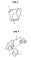
- FIG. 4 A second configuration of a mirror attachment used in the vehicle-mounted type of camera according to the present embodiment is described using Fig. 4 .
- Fig. 4 is a perspective view showing the second configuration of the mirror attachment used in the vehicle-mounted type of camera according to the first embodiment of the present invention.
- the same reference numbers or symbols as used in Fig. 1 designate the same elements.
- the mirror attachment can include a groove that extends in a longitudinal direction of the attachment.
- the groove 71 is provided in an enclosure 12A and a guide 72 is provided in the attachment 11A so that the attachment can be installed while being positioned at the groove 71.
- the enclosure 12A and the mirror attachment 11A can have a guide and a groove, respectively.
- the mirror attachment 11A can use screws as a fixing method therefor.
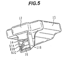
- Fig. 5 is a perspective view for explaining the first example of changing the installation angle of the mirror in the vehicle-mounted type of camera according to the first embodiment of the present invention.
- the same reference numbers or symbols as used in Fig. 1 designate the same elements.
- the installation angle of the mirror may need to be changed if the inclination angle of the windshield differs from that described above (i.e., if the vehicle in which the camera is to be installed is of a type different from that described above).
- a mirror attachment 11B therefore, includes a plurality of grooves 61A, 61B, and 61C beforehand that match a plurality of angles at which the mirror can be installed.
- the groove 61C is used to install the mirror 16 so that the inclination angle thereof is smaller.
- the mirror is installed in the groove 61A or 61B for a larger installation angle of the mirror. In this way, the installation angle of the mirror can be easily changed according to a particular loose classification of vehicles, such as sport utility vehicles (SUVs), sedans, or sports cars.
- SUVs sport utility vehicles
- sedans or sports cars.
- Fig. 6 is a perspective view for explaining the second example of changing the installation angle of the mirror in the vehicle-mounted type of camera according to the first embodiment of the present invention.
- Fig. 7 is a perspective view showing a configuration of a mirror installation pedestal in the second example of changing the installation angle of the mirror in the vehicle-mounted type of camera according to the first embodiment of the present invention.
- the same reference numbers or symbols as used in Fig. 1 designate the same elements.
- an attachment 11C has a knob 101.
- the angle of the mirror 16 can be changed to a desired value by rotating the knob 101.
- the knob 101 is coupled to a pedestal 102 having the mirror 16 installed thereon. Rotating the knob 101 moves the pedestal 102, thus making the angle of the mirror 16 changeable.
- Adoption of this structure makes stepless changing of the mirror angle possible, hence rendering the mirror applicable to substantially all kinds of vehicles.
- the pedestal 102 on which to install the mirror may have the mirror installed thereon or may be formed of aluminum to endow the pedestal itself with performance of a mirror.
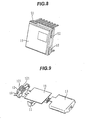
- Figs. 8 and 9 are perspective views for explaining the positioning structure of the imaging unit in the vehicle-mounted type of camera according to the first embodiment of the present invention.
- the same reference numbers or symbols as used in Fig. 1 designate the same elements.
- Fig. 8 shows a visual configuration of a CCD which is the imaging unit 15.
- the imaging unit 15 On a side thereof, the imaging unit 15 has reference planes 51 and 52 that serve as a basis for installation.
- Fig. 9 an exploded perspective view of the vehicle-mounted type of camera according to the present embodiment, shows the camera existing when Fig. 1 is viewed from underside.
- reference planes 121 and 122 for positioning are provided, which establishes the relationship in position between the imaging unit 15 and the lens 14, as shown in Fig. 1 . More specifically, in order to establish perpendicular position accuracy, the reference plane 121 with which the perpendicular reference plane 51 for the imaging unit 15 comes into contact is provided in the enclosure 12. In order to establish horizontal position accuracy, the reference plane 122 with which the horizontal reference plane 52 for the imaging unit comes into contact is also provided in the enclosure 12.
- the attachment 11 Since positional accuracy of the mirror 16 is another factor that significantly affects installation accuracy of the attachment 11, the attachment 11 is also assigned an accurate reference plane for positioning and fixing of the attachment. Misalignment in the direction of the optical axis can be minimized by realizing the highly accurate positional relationship between the mirror, the lens, and the imaging unit, in this way.
- the visual information to be acquired can be obtained by changing the installation location or imaging direction of the camera.
- changing the field angle of the lens that is, using a wider-angle lens allows a larger amount of information to be acquired, or using a telephoto lens allows images of distant objects to be intensively extracted.
- the changes for a lens of a different angle of field in such cases can also be easily conducted by adopting the attachment structure of the present embodiment.
- the camera can be used as a vehicle-interior supervisory camera by removing the mirror attachment 11.
- desired visual information can be acquired using a common enclosure, even in a vehicle-mounted type of camera more diversified in installation location or installation angle. Furthermore, the feelings of visual obstruction or oppression that may be caused to the driver when the vehicle-mounted type of camera is affixed to the windshield are minimized to make the camera applicable to various kinds of vehicles by introducing minimum changes in shape.
- a configuration of a vehicle-mounted type of camera according to a second embodiment of the present invention is described using Fig. 10 .
- Fig. 10 is a perspective view showing the configuration of the vehicle-mounted type of camera according to the second embodiment of the present invention.
- the same reference numbers or symbols as used in Fig. 1 designate the same elements.
- An enclosure 12A in the present embodiment is a member formed by integrating the enclosure 12 and attachment 11 shown in Fig. 1 .
- the mirror 16 is changed together with the enclosure 12A that is the integrated member.
- desired visual information can be acquired using a common enclosure, even in the vehicle-mounted type of camera more diversified in installation location or installation angle. Furthermore, the feelings of visual obstruction or oppression that may be caused to the driver when the vehicle-mounted type of camera is affixed to the windshield are minimized to make the camera applicable to various kinds of vehicles by introducing minimum changes in shape.
- Cameras designed to be installed near the windshield are in increasing demand for their vehicle-interior supervisory applications. For example, these cameras can be used to recognize the driver's or other front-seat passenger's body sizes, sitting positions on the seats, and the like, and change a way of unfolding airbags. These cameras are also useable for security purposes and can have functions such as imaging the vehicle interior for abnormalities.
- Fig. 11 is a perspective view showing a configuration of an attachment used in the vehicle-mounted type of camera according to the third embodiment of the present invention.
- Fig. 12 is a perspective view showing the configuration of the vehicle-mounted type of camera itself according to the third embodiment of the present invention.
- the same reference numbers or symbols as used in Fig. 1 designate the same elements.
- the attachment 11D in the present embodiment has a hole 81 at an installation surface of the mirror 16.
- the mirror 16 for vehicle-exterior supervisory purposes is installed in front of the attachment 11D, and the hole 81 for vehicle-interior supervisory purposes is provided at rear.
- Constructing the attachment in this way makes it possible to monitor the vehicle exterior from an image reflected from the mirror 16, and at the same time, to monitor the vehicle interior through the hole 81.
- both interior and exterior information of the vehicle can be acquired simultaneously. Image processing of these multiple kinds of visual information, therefore, makes it possible, for example, to detect the driver looking away or dozing off at the wheel, and at the same time to calculate a distance to the immediately preceding vehicle, judge a potential risk level of a collision, and alert the risk to the driver.
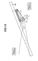
- a visual field rate of the vehicle interior and exterior in the vehicle-mounted type of camera according to the present embodiment is described using Fig. 13 .
- Fig. 13 is an explanatory diagram of the visual field rate of the vehicle interior and exterior in the vehicle-mounted type of camera according to the third embodiment of the present invention.
- the angle 91 needed to acquire information of the vehicle exterior is 22.5 degrees.
- a field angle of about 41 degrees is required for the camera to monitor the driver or other front-seat passenger, for example, to monitor, at a distance of 0.8 meters from the camera, an object with a height of about 90 cm, which is equal to seating height of an average adult male.
- An angle ⁇ 4 required for the camera to acquire information of the vehicle interior is the field angle described above.
- a ratio of the mirror 16 and the hole 81 is determined so that visual field information within 22.5 degrees only of the particular field angle range is imaged into part of an area of the imaging unit, and visual field information within 41 degrees, into the remaining area. That is to say, the ratio of the mirror 16 and the hole 81 is determined to be 35.4%:64.6%.
- the ratio of the mirror 16 and the hole 81 is determined to be 35.4%:64.6%.
- a total area size of the mirror and the hole amounts to about 16 mm.
- An area of 5.7 mm equivalent to 35.4% of this total area size is used as the mirror area, and 10.3 mm accounting for the remaining 64.6% is used as a size of the hole.
- Information on the interior and exterior of the vehicle can be acquired by determining the field angles required for information acquisition in each of the vehicle interior and exterior, and using the mirror 16 and the hole 81 with a total value of the two field angles as a field angle of the lens.
- desired visual information can be acquired using a common enclosure, even in the vehicle-mounted type of camera more diversified in installation location or installation angle. Furthermore, the feelings of visual obstruction or oppression that may be caused to the driver when the vehicle-mounted type of camera is affixed to the windshield are minimized to make the camera applicable to various kinds of vehicles by introducing minimum changes in shape.
- information on both the interior and exterior of the vehicle can be obtained with one camera.
- any of the attachment structures described per Figs. 1 to 13 is also applicable to a multi-camera arrangement and to a stereo camera configuration.
- one attachment can be used for all the plurality of cameras or the structure of the attachment or the installation angle of the mirror can be changed according to camera.
- Various pieces information can be acquired using multiple kinds of attachments.
Landscapes
- Engineering & Computer Science (AREA)
- Multimedia (AREA)
- Signal Processing (AREA)
- Mechanical Engineering (AREA)
- Fittings On The Vehicle Exterior For Carrying Loads, And Devices For Holding Or Mounting Articles (AREA)
- Traffic Control Systems (AREA)
- Studio Devices (AREA)
Applications Claiming Priority (1)
| Application Number | Priority Date | Filing Date | Title |
|---|---|---|---|
| JP2007208321A JP4667430B2 (ja) | 2007-08-09 | 2007-08-09 | 車載用カメラ |
Publications (3)
| Publication Number | Publication Date |
|---|---|
| EP2022676A2 true EP2022676A2 (de) | 2009-02-11 |
| EP2022676A3 EP2022676A3 (de) | 2009-06-17 |
| EP2022676B1 EP2022676B1 (de) | 2010-06-30 |
Family
ID=39730762
Family Applications (1)
| Application Number | Title | Priority Date | Filing Date |
|---|---|---|---|
| EP08013736A Active EP2022676B1 (de) | 2007-08-09 | 2008-07-31 | Kamera zur Montage in einem Kraftfahrzeug |
Country Status (4)
| Country | Link |
|---|---|
| US (1) | US8223203B2 (de) |
| EP (1) | EP2022676B1 (de) |
| JP (1) | JP4667430B2 (de) |
| DE (1) | DE602008001633D1 (de) |
Cited By (2)
| Publication number | Priority date | Publication date | Assignee | Title |
|---|---|---|---|---|
| WO2013056700A1 (de) * | 2011-10-20 | 2013-04-25 | Continental Automotive Gmbh | Optische vorrichtung für ein fahrzeug |
| US10882464B2 (en) | 2016-08-01 | 2021-01-05 | Sony Semiconductor Solutions Corporation | Vehicle-mounted camera, vehicle-mounted camera apparatus, and method of supporting vehicle-mounted camera |
Families Citing this family (51)
| Publication number | Priority date | Publication date | Assignee | Title |
|---|---|---|---|---|
| WO2010111173A1 (en) * | 2009-03-23 | 2010-09-30 | Magna Mirrors Of America, Inc. | Interior mirror assembly with adjustable mounting assembly |
| JP5691188B2 (ja) * | 2010-02-12 | 2015-04-01 | ソニー株式会社 | カメラ装置 |
| DE102010003666B4 (de) * | 2010-04-07 | 2019-07-04 | Robert Bosch Gmbh | Kamera für ein Fahrzeug und Anordnung aus einer Kamera und einem Kamerahalter |
| DE102010045214A1 (de) * | 2010-09-13 | 2012-03-15 | Audi Ag | Kameraanordnung für ein Fahrzeug und Verfahren zum Einbau einer Kameraanordnung in ein Fahrzeug |
| JP5645634B2 (ja) * | 2010-12-15 | 2014-12-24 | キヤノン株式会社 | 撮像装置 |
| JP2012131390A (ja) * | 2010-12-22 | 2012-07-12 | Rohm Co Ltd | 車載カメラ |
| DE102011008969A1 (de) * | 2011-01-20 | 2012-07-26 | Man Nutzfahrzeuge Ag | Strömungsoptimiertes Gehäuse an der Frontscheibe eines Kraftfahrzeugs |
| US9380219B2 (en) | 2011-04-20 | 2016-06-28 | Magna Electronics Inc. | Angular filter for vehicle mounted cameras |
| US20140285913A1 (en) | 2011-06-20 | 2014-09-25 | Rhp Multimedia Corp. | Moveable mirror assembly for electronic device case |
| CN103763972A (zh) * | 2011-06-20 | 2014-04-30 | Rhp多媒体公司 | 用于便携式电子装置的外壳 |
| US9596387B2 (en) | 2011-08-02 | 2017-03-14 | Magna Electronics Inc. | Vehicular camera system |
| US9487159B2 (en) | 2011-08-02 | 2016-11-08 | Magna Electronics Inc. | Vehicle vision system with camera module mounting bracket |
| US9871971B2 (en) | 2011-08-02 | 2018-01-16 | Magma Electronics Inc. | Vehicle vision system with light baffling system |
| DE102013200966B4 (de) | 2012-02-10 | 2023-11-16 | Robert Bosch Gmbh | Modulvorrichtung für ein Kamerasystem und entsprechendes Kamerasystem |
| DE102012101781B4 (de) * | 2012-03-02 | 2014-07-10 | Continental Automotive Gmbh | Halterahmen für Sensorvorrichtungen in Fahrzeugen |
| JP6028382B2 (ja) * | 2012-04-27 | 2016-11-16 | 株式会社デンソー | 前方監視カメラ |
| US9896039B2 (en) | 2014-05-09 | 2018-02-20 | Magna Electronics Inc. | Vehicle vision system with forward viewing camera |
| JP2016085187A (ja) * | 2014-10-29 | 2016-05-19 | オムロンオートモーティブエレクトロニクス株式会社 | レーザレーダ装置 |
| US10112552B2 (en) | 2015-03-11 | 2018-10-30 | Magna Electronics Inc. | Vehicle vision system with camera viewing through windshield |
| JP6421691B2 (ja) | 2015-04-28 | 2018-11-14 | 株式会社デンソー | カメラ装置 |
| JP6519355B2 (ja) * | 2015-06-30 | 2019-05-29 | 株式会社デンソー | カメラ装置及び車載システム |
| USD862441S1 (en) | 2015-12-03 | 2019-10-08 | Scandit Ag | Case for a mobile device |
| CN110393003B (zh) * | 2017-01-09 | 2022-02-01 | 乔伊森安全系统收购有限责任公司 | 用于乘员监控系统的紧凑型相机模块 |
| USD860180S1 (en) | 2017-01-12 | 2019-09-17 | Scandit Ag | Case for a mobile communications device |
| JP6839579B2 (ja) * | 2017-03-23 | 2021-03-10 | 矢崎エナジーシステム株式会社 | 車載カメラ用カバー |
| JP6720952B2 (ja) * | 2017-11-21 | 2020-07-08 | オムロン株式会社 | 乗員監視装置 |
| EP3738302A2 (de) | 2018-01-08 | 2020-11-18 | Scandit AG | Gehäuse einer mobilen vorrichtung und verfahren zur bildgebung mit mehreren ansichten |
| US10846561B1 (en) | 2020-04-01 | 2020-11-24 | Scandit Ag | Recognition and selection of discrete patterns within a scene or image |
| US12307552B2 (en) | 2018-01-08 | 2025-05-20 | Scandit Ag | Selection and decoding of an optical pattern within a real scene using a frozen image from a video preview |
| US10957023B2 (en) | 2018-10-05 | 2021-03-23 | Magna Electronics Inc. | Vehicular vision system with reduced windshield blackout opening |
| US11087105B1 (en) | 2020-05-15 | 2021-08-10 | Scandit Ag | Performance improvements for recognition of optical patterns in images |
| US11216628B2 (en) | 2020-04-01 | 2022-01-04 | Scandit Ag | High-speed scanning of optical patterns using a digital camera |
| US11295163B1 (en) | 2020-04-01 | 2022-04-05 | Scandit Ag | Recognition of optical patterns in images acquired by a robotic device |
| US11514665B2 (en) | 2020-04-01 | 2022-11-29 | Scandit Ag | Mapping optical-code images to an overview image |
| US11922271B1 (en) | 2020-05-15 | 2024-03-05 | Scandit Ag | Virtual screen standby mode for mobile device camera |
| US11244147B2 (en) | 2020-05-15 | 2022-02-08 | Scandit Ag | Optical data exchange while preserving social distancing |
| US11290643B1 (en) | 2020-06-26 | 2022-03-29 | Scandit Ag | Efficient digital camera image acquisition and analysis |
| US11403477B1 (en) | 2020-05-15 | 2022-08-02 | Scandit Ag | Image exposure performance improvements for recognition of optical patterns |
| US12380571B1 (en) | 2020-05-15 | 2025-08-05 | Scandit Ag | Image analysis for scanning optical patterns in a real scene at dynamic ranges |
| US11417001B1 (en) | 2020-07-27 | 2022-08-16 | Scandit Ag | Detecting discrete optical patterns using depth estimation |
| US12488473B1 (en) | 2020-07-27 | 2025-12-02 | Scandit Ag | Multi-barcode detection in a real scene using interface enhancement based on user input |
| US11880738B1 (en) | 2021-08-17 | 2024-01-23 | Scandit Ag | Visual odometry for optical pattern scanning in a real scene |
| US12175327B1 (en) | 2020-12-04 | 2024-12-24 | Scandit Ag | Camera start optimization for optical pattern decoding |
| US11495036B1 (en) | 2021-01-29 | 2022-11-08 | Scandit Ag | Segmenting images for optical character recognition |
| US12145513B2 (en) * | 2021-10-11 | 2024-11-19 | Magna Electronics Inc. | Vehicular windshield-mounted forward camera vision system |
| US12208739B2 (en) | 2022-01-13 | 2025-01-28 | Magna Electronics Inc. | Vehicular camera assembly process with enhanced attachment of imager assembly at camera housing |
| US11557136B1 (en) | 2022-02-23 | 2023-01-17 | Scandit Ag | Identity document verification based on barcode structure |
| USD1110929S1 (en) * | 2024-01-26 | 2026-02-03 | Dongguan Daozhi Electronic Technology Co., Ltd. | Driving recorder case |
| USD1100801S1 (en) * | 2024-04-03 | 2025-11-04 | Dongguan Daozhi Electronic Technology Co., Ltd. | Driving recorder case |
| USD1101658S1 (en) * | 2024-04-03 | 2025-11-11 | Dongguan Daozhi Electronic Technology Co., Ltd. | Driving recorder case |
| USD1100800S1 (en) * | 2024-04-03 | 2025-11-04 | Dongguan Daozhi Electronic Technology Co., Ltd. | Driving recorder case |
Citations (4)
| Publication number | Priority date | Publication date | Assignee | Title |
|---|---|---|---|---|
| US6392218B1 (en) | 2000-04-07 | 2002-05-21 | Iteris, Inc. | Vehicle rain sensor |
| JP2003335180A (ja) | 2002-05-17 | 2003-11-25 | Fuji Heavy Ind Ltd | センサの支持構造およびその組付方法 |
| US20070025596A1 (en) | 2005-05-20 | 2007-02-01 | Valeo Vision | Device for detecting obstacles comprising an imaging system for motor vehicles |
| WO2007091247A1 (en) | 2006-02-06 | 2007-08-16 | Yefim Kereth | Window mounting arrangement |
Family Cites Families (13)
| Publication number | Priority date | Publication date | Assignee | Title |
|---|---|---|---|---|
| JPH089362A (ja) * | 1994-06-15 | 1996-01-12 | Konica Corp | 左右反転画像出力ビデオカメラ |
| JPH09104291A (ja) * | 1995-06-27 | 1997-04-22 | Utec Kk | 車輛端部側方確認装置 |
| US20020067426A1 (en) * | 1997-04-10 | 2002-06-06 | Hideki Nagata | Electronic camera having a phoelectric sensor device |
| US6326613B1 (en) * | 1998-01-07 | 2001-12-04 | Donnelly Corporation | Vehicle interior mirror assembly adapted for containing a rain sensor |
| JP3349412B2 (ja) * | 1997-09-13 | 2002-11-25 | 本田技研工業株式会社 | 車両搭載カメラ |
| AU2002256810A1 (en) * | 2001-05-23 | 2002-12-03 | Trevor Keith Byford | Vehicle incident recorder |
| JP2003154893A (ja) * | 2001-11-21 | 2003-05-27 | Niles Parts Co Ltd | 間接撮影型カメラ取付構造 |
| JP2004075033A (ja) * | 2002-08-17 | 2004-03-11 | Hisao Saito | 車載型自動車事故自動動画撮影録画記録装置及びその記録方法 |
| JP2004200960A (ja) * | 2002-12-18 | 2004-07-15 | Konica Minolta Holdings Inc | 撮像装置の組付方法及び撮像装置 |
| JP2004276733A (ja) * | 2003-03-14 | 2004-10-07 | Toyota Motor Corp | 車載カメラ搭載構造 |
| JP2007263563A (ja) * | 2004-06-03 | 2007-10-11 | Matsushita Electric Ind Co Ltd | カメラモジュール |
| DE102006004260A1 (de) * | 2006-01-31 | 2007-08-02 | Bayerische Motoren Werke Ag | Kamerasystem für ein Kraftfahrzeug |
| JP4677364B2 (ja) * | 2006-05-23 | 2011-04-27 | 株式会社村上開明堂 | 車両監視装置 |
-
2007
- 2007-08-09 JP JP2007208321A patent/JP4667430B2/ja active Active
-
2008
- 2008-07-31 EP EP08013736A patent/EP2022676B1/de active Active
- 2008-07-31 DE DE602008001633T patent/DE602008001633D1/de active Active
- 2008-08-06 US US12/186,980 patent/US8223203B2/en active Active
Patent Citations (4)
| Publication number | Priority date | Publication date | Assignee | Title |
|---|---|---|---|---|
| US6392218B1 (en) | 2000-04-07 | 2002-05-21 | Iteris, Inc. | Vehicle rain sensor |
| JP2003335180A (ja) | 2002-05-17 | 2003-11-25 | Fuji Heavy Ind Ltd | センサの支持構造およびその組付方法 |
| US20070025596A1 (en) | 2005-05-20 | 2007-02-01 | Valeo Vision | Device for detecting obstacles comprising an imaging system for motor vehicles |
| WO2007091247A1 (en) | 2006-02-06 | 2007-08-16 | Yefim Kereth | Window mounting arrangement |
Cited By (2)
| Publication number | Priority date | Publication date | Assignee | Title |
|---|---|---|---|---|
| WO2013056700A1 (de) * | 2011-10-20 | 2013-04-25 | Continental Automotive Gmbh | Optische vorrichtung für ein fahrzeug |
| US10882464B2 (en) | 2016-08-01 | 2021-01-05 | Sony Semiconductor Solutions Corporation | Vehicle-mounted camera, vehicle-mounted camera apparatus, and method of supporting vehicle-mounted camera |
Also Published As
| Publication number | Publication date |
|---|---|
| DE602008001633D1 (de) | 2010-08-12 |
| EP2022676B1 (de) | 2010-06-30 |
| EP2022676A3 (de) | 2009-06-17 |
| JP4667430B2 (ja) | 2011-04-13 |
| JP2009040270A (ja) | 2009-02-26 |
| US20090046149A1 (en) | 2009-02-19 |
| US8223203B2 (en) | 2012-07-17 |
Similar Documents
| Publication | Publication Date | Title |
|---|---|---|
| EP2022676B1 (de) | Kamera zur Montage in einem Kraftfahrzeug | |
| US11951900B2 (en) | Vehicular forward viewing image capture system | |
| US12384304B2 (en) | Vehicular camera monitoring system | |
| US8912476B2 (en) | Automatic vehicle exterior light control system assemblies | |
| US8199975B2 (en) | System and method for side vision detection of obstacles for vehicles | |
| US10137842B2 (en) | Camera system for a vehicle | |
| EP1764835B1 (de) | Multifunktioneller optischer Sensor mit einer an Mikrolinsen gekoppelten Matrix von Photodetektoren | |
| EP3770020B1 (de) | Abbildungssystem und fahrzeugfenster dafür | |
| US10112552B2 (en) | Vehicle vision system with camera viewing through windshield | |
| US12340546B2 (en) | Vehicular occupant monitoring system using centralized camera with expanded view | |
| US11152726B2 (en) | Connector device and connector system | |
| EP4660014A1 (de) | Fahrzeugbildgebungsvorrichtung |
Legal Events
| Date | Code | Title | Description |
|---|---|---|---|
| PUAI | Public reference made under article 153(3) epc to a published international application that has entered the european phase |
Free format text: ORIGINAL CODE: 0009012 |
|
| AK | Designated contracting states |
Kind code of ref document: A2 Designated state(s): AT BE BG CH CY CZ DE DK EE ES FI FR GB GR HR HU IE IS IT LI LT LU LV MC MT NL NO PL PT RO SE SI SK TR |
|
| AX | Request for extension of the european patent |
Extension state: AL BA MK RS |
|
| PUAL | Search report despatched |
Free format text: ORIGINAL CODE: 0009013 |
|
| 17P | Request for examination filed |
Effective date: 20090416 |
|
| AK | Designated contracting states |
Kind code of ref document: A3 Designated state(s): AT BE BG CH CY CZ DE DK EE ES FI FR GB GR HR HU IE IS IT LI LT LU LV MC MT NL NO PL PT RO SE SI SK TR |
|
| AX | Request for extension of the european patent |
Extension state: AL BA MK RS |
|
| RIC1 | Information provided on ipc code assigned before grant |
Ipc: H04N 7/18 20060101AFI20090513BHEP Ipc: B60R 1/00 20060101ALI20090513BHEP Ipc: B60R 11/04 20060101ALI20090513BHEP |
|
| 17Q | First examination report despatched |
Effective date: 20090901 |
|
| GRAP | Despatch of communication of intention to grant a patent |
Free format text: ORIGINAL CODE: EPIDOSNIGR1 |
|
| AKX | Designation fees paid |
Designated state(s): DE FR GB IT |
|
| GRAS | Grant fee paid |
Free format text: ORIGINAL CODE: EPIDOSNIGR3 |
|
| GRAA | (expected) grant |
Free format text: ORIGINAL CODE: 0009210 |
|
| AK | Designated contracting states |
Kind code of ref document: B1 Designated state(s): DE FR GB IT |
|
| REG | Reference to a national code |
Ref country code: GB Ref legal event code: FG4D |
|
| REF | Corresponds to: |
Ref document number: 602008001633 Country of ref document: DE Date of ref document: 20100812 Kind code of ref document: P |
|
| PLBE | No opposition filed within time limit |
Free format text: ORIGINAL CODE: 0009261 |
|
| STAA | Information on the status of an ep patent application or granted ep patent |
Free format text: STATUS: NO OPPOSITION FILED WITHIN TIME LIMIT |
|
| 26N | No opposition filed |
Effective date: 20110331 |
|
| REG | Reference to a national code |
Ref country code: DE Ref legal event code: R097 Ref document number: 602008001633 Country of ref document: DE Effective date: 20110330 |
|
| PGFP | Annual fee paid to national office [announced via postgrant information from national office to epo] |
Ref country code: GB Payment date: 20120725 Year of fee payment: 5 |
|
| PGFP | Annual fee paid to national office [announced via postgrant information from national office to epo] |
Ref country code: IT Payment date: 20120718 Year of fee payment: 5 |
|
| GBPC | Gb: european patent ceased through non-payment of renewal fee |
Effective date: 20130731 |
|
| PG25 | Lapsed in a contracting state [announced via postgrant information from national office to epo] |
Ref country code: GB Free format text: LAPSE BECAUSE OF NON-PAYMENT OF DUE FEES Effective date: 20130731 |
|
| PG25 | Lapsed in a contracting state [announced via postgrant information from national office to epo] |
Ref country code: IT Free format text: LAPSE BECAUSE OF NON-PAYMENT OF DUE FEES Effective date: 20130731 |
|
| REG | Reference to a national code |
Ref country code: FR Ref legal event code: PLFP Year of fee payment: 9 |
|
| REG | Reference to a national code |
Ref country code: FR Ref legal event code: PLFP Year of fee payment: 10 |
|
| REG | Reference to a national code |
Ref country code: FR Ref legal event code: PLFP Year of fee payment: 11 |
|
| REG | Reference to a national code |
Ref country code: DE Ref legal event code: R081 Ref document number: 602008001633 Country of ref document: DE Owner name: HITACHI ASTEMO, LTD., HITACHINAKA-SHI, JP Free format text: FORMER OWNER: HITACHI AUTOMOTIVE SYSTEMS, LTD., HITACHINAKA-SHI, IBARAKI, JP Ref country code: DE Ref legal event code: R081 Ref document number: 602008001633 Country of ref document: DE Owner name: HITACHI ASTEMO, LTD., HITACHINAKA-SHI, JP Free format text: FORMER OWNER: HITACHI, LTD., TOKYO, JP |
|
| PGFP | Annual fee paid to national office [announced via postgrant information from national office to epo] |
Ref country code: FR Payment date: 20250610 Year of fee payment: 18 |
|
| PGFP | Annual fee paid to national office [announced via postgrant information from national office to epo] |
Ref country code: DE Payment date: 20250604 Year of fee payment: 18 |