EP2020923B2 - In-situ measurement of physical parameters - Google Patents
In-situ measurement of physical parameters Download PDFInfo
- Publication number
- EP2020923B2 EP2020923B2 EP07858836.5A EP07858836A EP2020923B2 EP 2020923 B2 EP2020923 B2 EP 2020923B2 EP 07858836 A EP07858836 A EP 07858836A EP 2020923 B2 EP2020923 B2 EP 2020923B2
- Authority
- EP
- European Patent Office
- Prior art keywords
- data
- temperature
- measurements
- data logger
- user
- Prior art date
- Legal status (The legal status is an assumption and is not a legal conclusion. Google has not performed a legal analysis and makes no representation as to the accuracy of the status listed.)
- Active
Links
- 238000012625 in-situ measurement Methods 0.000 title description 5
- 238000005259 measurement Methods 0.000 claims description 63
- 230000036760 body temperature Effects 0.000 claims description 43
- 230000033001 locomotion Effects 0.000 claims description 38
- 238000009529 body temperature measurement Methods 0.000 claims description 37
- 238000000034 method Methods 0.000 claims description 23
- 230000005540 biological transmission Effects 0.000 claims description 18
- 230000008859 change Effects 0.000 claims description 14
- 230000036757 core body temperature Effects 0.000 claims description 11
- 239000000853 adhesive Substances 0.000 claims description 9
- 230000001070 adhesive effect Effects 0.000 claims description 9
- 241001465754 Metazoa Species 0.000 claims description 6
- 238000003860 storage Methods 0.000 claims description 6
- 238000004891 communication Methods 0.000 claims description 5
- 230000000737 periodic effect Effects 0.000 claims description 5
- 230000008569 process Effects 0.000 claims description 5
- 230000001681 protective effect Effects 0.000 claims description 3
- 238000002513 implantation Methods 0.000 claims description 2
- 230000016087 ovulation Effects 0.000 description 29
- 239000007943 implant Substances 0.000 description 14
- 230000005672 electromagnetic field Effects 0.000 description 10
- 230000000694 effects Effects 0.000 description 9
- 229920001296 polysiloxane Polymers 0.000 description 9
- 238000012545 processing Methods 0.000 description 9
- 230000006872 improvement Effects 0.000 description 8
- 238000012937 correction Methods 0.000 description 7
- 210000003097 mucus Anatomy 0.000 description 7
- 210000003756 cervix mucus Anatomy 0.000 description 6
- 239000000463 material Substances 0.000 description 6
- 238000004364 calculation method Methods 0.000 description 5
- 238000012544 monitoring process Methods 0.000 description 5
- 230000008878 coupling Effects 0.000 description 4
- 238000010168 coupling process Methods 0.000 description 4
- 238000005859 coupling reaction Methods 0.000 description 4
- 238000010586 diagram Methods 0.000 description 4
- 230000006870 function Effects 0.000 description 4
- 208000002193 Pain Diseases 0.000 description 3
- 238000004458 analytical method Methods 0.000 description 3
- 210000004369 blood Anatomy 0.000 description 3
- 239000008280 blood Substances 0.000 description 3
- 238000001514 detection method Methods 0.000 description 3
- 235000013601 eggs Nutrition 0.000 description 3
- 230000007613 environmental effect Effects 0.000 description 3
- 230000005906 menstruation Effects 0.000 description 3
- 238000012806 monitoring device Methods 0.000 description 3
- 230000027758 ovulation cycle Effects 0.000 description 3
- 230000036407 pain Effects 0.000 description 3
- 230000004044 response Effects 0.000 description 3
- 238000005070 sampling Methods 0.000 description 3
- 102000002322 Egg Proteins Human genes 0.000 description 2
- 108010000912 Egg Proteins Proteins 0.000 description 2
- 206010037660 Pyrexia Diseases 0.000 description 2
- 238000013459 approach Methods 0.000 description 2
- 230000008901 benefit Effects 0.000 description 2
- 239000003990 capacitor Substances 0.000 description 2
- 230000006835 compression Effects 0.000 description 2
- 238000007906 compression Methods 0.000 description 2
- 238000007796 conventional method Methods 0.000 description 2
- 230000000875 corresponding effect Effects 0.000 description 2
- 230000035558 fertility Effects 0.000 description 2
- 239000012530 fluid Substances 0.000 description 2
- 229940088597 hormone Drugs 0.000 description 2
- 239000005556 hormone Substances 0.000 description 2
- 238000011065 in-situ storage Methods 0.000 description 2
- 239000012212 insulator Substances 0.000 description 2
- 230000003993 interaction Effects 0.000 description 2
- 238000004519 manufacturing process Methods 0.000 description 2
- 230000000624 ovulatory effect Effects 0.000 description 2
- 230000035790 physiological processes and functions Effects 0.000 description 2
- 230000035935 pregnancy Effects 0.000 description 2
- 230000000284 resting effect Effects 0.000 description 2
- 238000005096 rolling process Methods 0.000 description 2
- 238000012546 transfer Methods 0.000 description 2
- QCVGEOXPDFCNHA-UHFFFAOYSA-N 5,5-dimethyl-2,4-dioxo-1,3-oxazolidine-3-carboxamide Chemical compound CC1(C)OC(=O)N(C(N)=O)C1=O QCVGEOXPDFCNHA-UHFFFAOYSA-N 0.000 description 1
- 206010000084 Abdominal pain lower Diseases 0.000 description 1
- 206010067484 Adverse reaction Diseases 0.000 description 1
- 241001408627 Agriopis marginaria Species 0.000 description 1
- 238000012935 Averaging Methods 0.000 description 1
- 208000031636 Body Temperature Changes Diseases 0.000 description 1
- 206010006313 Breast tenderness Diseases 0.000 description 1
- WQZGKKKJIJFFOK-GASJEMHNSA-N Glucose Natural products OC[C@H]1OC(O)[C@H](O)[C@@H](O)[C@@H]1O WQZGKKKJIJFFOK-GASJEMHNSA-N 0.000 description 1
- 206010021113 Hypothermia Diseases 0.000 description 1
- WHXSMMKQMYFTQS-UHFFFAOYSA-N Lithium Chemical group [Li] WHXSMMKQMYFTQS-UHFFFAOYSA-N 0.000 description 1
- 206010036772 Proctalgia Diseases 0.000 description 1
- XUIMIQQOPSSXEZ-UHFFFAOYSA-N Silicon Chemical compound [Si] XUIMIQQOPSSXEZ-UHFFFAOYSA-N 0.000 description 1
- 210000001015 abdomen Anatomy 0.000 description 1
- 206010000059 abdominal discomfort Diseases 0.000 description 1
- 208000020560 abdominal swelling Diseases 0.000 description 1
- 230000001133 acceleration Effects 0.000 description 1
- 230000001154 acute effect Effects 0.000 description 1
- 230000003044 adaptive effect Effects 0.000 description 1
- 230000002411 adverse Effects 0.000 description 1
- 230000006838 adverse reaction Effects 0.000 description 1
- 230000003190 augmentative effect Effects 0.000 description 1
- 230000009286 beneficial effect Effects 0.000 description 1
- 230000000740 bleeding effect Effects 0.000 description 1
- 230000036772 blood pressure Effects 0.000 description 1
- 210000001124 body fluid Anatomy 0.000 description 1
- 239000010839 body fluid Substances 0.000 description 1
- 230000015556 catabolic process Effects 0.000 description 1
- 230000003750 conditioning effect Effects 0.000 description 1
- 239000004020 conductor Substances 0.000 description 1
- 238000010276 construction Methods 0.000 description 1
- 230000002596 correlated effect Effects 0.000 description 1
- 230000007797 corrosion Effects 0.000 description 1
- 238000005260 corrosion Methods 0.000 description 1
- 238000013500 data storage Methods 0.000 description 1
- 238000006731 degradation reaction Methods 0.000 description 1
- 238000003745 diagnosis Methods 0.000 description 1
- 238000009826 distribution Methods 0.000 description 1
- 235000014103 egg white Nutrition 0.000 description 1
- 210000000969 egg white Anatomy 0.000 description 1
- 230000004720 fertilization Effects 0.000 description 1
- 230000027950 fever generation Effects 0.000 description 1
- 239000006260 foam Substances 0.000 description 1
- 239000008103 glucose Substances 0.000 description 1
- 230000005484 gravity Effects 0.000 description 1
- 230000000774 hypoallergenic effect Effects 0.000 description 1
- 230000002631 hypothermal effect Effects 0.000 description 1
- 210000000987 immune system Anatomy 0.000 description 1
- 208000015181 infectious disease Diseases 0.000 description 1
- 208000021267 infertility disease Diseases 0.000 description 1
- 238000002347 injection Methods 0.000 description 1
- 239000007924 injection Substances 0.000 description 1
- 230000001788 irregular Effects 0.000 description 1
- 238000002955 isolation Methods 0.000 description 1
- 238000012886 linear function Methods 0.000 description 1
- 239000007788 liquid Substances 0.000 description 1
- 229910052744 lithium Inorganic materials 0.000 description 1
- 230000007774 longterm Effects 0.000 description 1
- 239000000314 lubricant Substances 0.000 description 1
- 238000010339 medical test Methods 0.000 description 1
- 230000002175 menstrual effect Effects 0.000 description 1
- 239000002184 metal Substances 0.000 description 1
- 229910052751 metal Inorganic materials 0.000 description 1
- 239000002923 metal particle Substances 0.000 description 1
- 238000012986 modification Methods 0.000 description 1
- 230000004048 modification Effects 0.000 description 1
- 210000004681 ovum Anatomy 0.000 description 1
- 230000035699 permeability Effects 0.000 description 1
- 230000000704 physical effect Effects 0.000 description 1
- 239000011505 plaster Substances 0.000 description 1
- 229920001084 poly(chloroprene) Polymers 0.000 description 1
- 229920000642 polymer Polymers 0.000 description 1
- 230000000750 progressive effect Effects 0.000 description 1
- 230000009467 reduction Effects 0.000 description 1
- 230000002441 reversible effect Effects 0.000 description 1
- 230000033764 rhythmic process Effects 0.000 description 1
- 239000011435 rock Substances 0.000 description 1
- 210000003296 saliva Anatomy 0.000 description 1
- 230000035945 sensitivity Effects 0.000 description 1
- 229910052710 silicon Inorganic materials 0.000 description 1
- 239000010703 silicon Substances 0.000 description 1
- 230000004622 sleep time Effects 0.000 description 1
- 239000000243 solution Substances 0.000 description 1
- 238000013179 statistical model Methods 0.000 description 1
- 238000012360 testing method Methods 0.000 description 1
- 238000012549 training Methods 0.000 description 1
- 210000002700 urine Anatomy 0.000 description 1
- 230000000007 visual effect Effects 0.000 description 1
- 230000002618 waking effect Effects 0.000 description 1
- 229910000859 α-Fe Inorganic materials 0.000 description 1
Images


Classifications
-
- A—HUMAN NECESSITIES
- A61—MEDICAL OR VETERINARY SCIENCE; HYGIENE
- A61B—DIAGNOSIS; SURGERY; IDENTIFICATION
- A61B10/00—Instruments for taking body samples for diagnostic purposes; Other methods or instruments for diagnosis, e.g. for vaccination diagnosis, sex determination or ovulation-period determination; Throat striking implements
- A61B10/0012—Ovulation-period determination
-
- A—HUMAN NECESSITIES
- A61—MEDICAL OR VETERINARY SCIENCE; HYGIENE
- A61B—DIAGNOSIS; SURGERY; IDENTIFICATION
- A61B5/00—Measuring for diagnostic purposes; Identification of persons
- A61B5/0002—Remote monitoring of patients using telemetry, e.g. transmission of vital signals via a communication network
- A61B5/0004—Remote monitoring of patients using telemetry, e.g. transmission of vital signals via a communication network characterised by the type of physiological signal transmitted
- A61B5/0008—Temperature signals
-
- A—HUMAN NECESSITIES
- A61—MEDICAL OR VETERINARY SCIENCE; HYGIENE
- A61B—DIAGNOSIS; SURGERY; IDENTIFICATION
- A61B5/00—Measuring for diagnostic purposes; Identification of persons
- A61B5/0002—Remote monitoring of patients using telemetry, e.g. transmission of vital signals via a communication network
- A61B5/0031—Implanted circuitry
-
- A—HUMAN NECESSITIES
- A61—MEDICAL OR VETERINARY SCIENCE; HYGIENE
- A61B—DIAGNOSIS; SURGERY; IDENTIFICATION
- A61B5/00—Measuring for diagnostic purposes; Identification of persons
- A61B5/41—Detecting, measuring or recording for evaluating the immune or lymphatic systems
- A61B5/411—Detecting or monitoring allergy or intolerance reactions to an allergenic agent or substance
-
- A—HUMAN NECESSITIES
- A61—MEDICAL OR VETERINARY SCIENCE; HYGIENE
- A61B—DIAGNOSIS; SURGERY; IDENTIFICATION
- A61B10/00—Instruments for taking body samples for diagnostic purposes; Other methods or instruments for diagnosis, e.g. for vaccination diagnosis, sex determination or ovulation-period determination; Throat striking implements
- A61B10/0012—Ovulation-period determination
- A61B2010/0019—Ovulation-period determination based on measurement of temperature
-
- A—HUMAN NECESSITIES
- A61—MEDICAL OR VETERINARY SCIENCE; HYGIENE
- A61B—DIAGNOSIS; SURGERY; IDENTIFICATION
- A61B17/00—Surgical instruments, devices or methods
- A61B2017/00681—Aspects not otherwise provided for
- A61B2017/00734—Aspects not otherwise provided for battery operated
-
- A—HUMAN NECESSITIES
- A61—MEDICAL OR VETERINARY SCIENCE; HYGIENE
- A61B—DIAGNOSIS; SURGERY; IDENTIFICATION
- A61B2560/00—Constructional details of operational features of apparatus; Accessories for medical measuring apparatus
- A61B2560/02—Operational features
- A61B2560/0204—Operational features of power management
- A61B2560/0214—Operational features of power management of power generation or supply
- A61B2560/0219—Operational features of power management of power generation or supply of externally powered implanted units
-
- A—HUMAN NECESSITIES
- A61—MEDICAL OR VETERINARY SCIENCE; HYGIENE
- A61B—DIAGNOSIS; SURGERY; IDENTIFICATION
- A61B5/00—Measuring for diagnostic purposes; Identification of persons
- A61B5/72—Signal processing specially adapted for physiological signals or for diagnostic purposes
- A61B5/7232—Signal processing specially adapted for physiological signals or for diagnostic purposes involving compression of the physiological signal, e.g. to extend the signal recording period
-
- G—PHYSICS
- G16—INFORMATION AND COMMUNICATION TECHNOLOGY [ICT] SPECIALLY ADAPTED FOR SPECIFIC APPLICATION FIELDS
- G16H—HEALTHCARE INFORMATICS, i.e. INFORMATION AND COMMUNICATION TECHNOLOGY [ICT] SPECIALLY ADAPTED FOR THE HANDLING OR PROCESSING OF MEDICAL OR HEALTHCARE DATA
- G16H40/00—ICT specially adapted for the management or administration of healthcare resources or facilities; ICT specially adapted for the management or operation of medical equipment or devices
- G16H40/60—ICT specially adapted for the management or administration of healthcare resources or facilities; ICT specially adapted for the management or operation of medical equipment or devices for the operation of medical equipment or devices
- G16H40/63—ICT specially adapted for the management or administration of healthcare resources or facilities; ICT specially adapted for the management or operation of medical equipment or devices for the operation of medical equipment or devices for local operation
Definitions
- This invention relates to a data logger device for in-situ measurement of one or more physical parameters, to a system for in-situ measurement of one or more physical parameters, to a system for determining the point of ovulation in a female, and to a system for in-situ measurement of temperature.
- Data logger devices for measuring and storing physical parameters are widely used across the engineering and scientific worlds. Such devices allow the automated monitoring of physical parameters in-situ over long timescales, in difficult to reach locations or in environmentally dangerous conditions - situations in which manual measurements may be inconvenient or overly time-consuming.
- MiniMitter system http://www.minimitter.com ) for logging temperature.
- the cost of the total solution is rather high, and the data logger itself is rather cumbersome and too large for many applications.
- Physiological parameters may be measured "by hand", for example by a doctor or nurse, or may be monitored by (often expensive) medical apparatus to which a patient is required to remain connected for the duration that the measurement in question is required.
- an implantable device would best facilitate the measurement of these parameters. It is desirable for implanted medical devices to have as long a lifetime as possible within the patient, in as small as possible volume. In many devices, this is limited by a trade-off between battery life and battery size, and necessitates removal and reinsertion of the device simply for the purposes of recharging or replacing this battery. This causes undue stress and discomfort for the patient.
- European Patent Application No. 0195207 describes a uterine implant for periodic logging of temperature data, which is wirelessly transmitted to a receiver on demand for analysis and display. This solves a significant problem in the use of the Basal Body Temperature (BBT) method for natural family planning, in that the user need not wake for, nor even remember to take temperature measurements, on a daily basis.
- BBT Basal Body Temperature
- the device must be periodically withdrawn and reinserted due to the need to replace or recharge the battery in the device. Although introduced into an accessible body cavity, this withdrawal and reinsertion procedure is highly, inconvenient and has significant associated medical risks.
- an implant device that does not store the data measurements at the implant device but transmits the measurements directly to a reader.
- the power for the implant may be supplied by the reader, such as in European Patent Application No. 0476730 .
- This is common for passive radiofrequency identification (RF-ID) sensors.
- RF-ID passive radiofrequency identification
- German Patent Nos. 10345282 and 19943456 both describe temperature-based ovulation detection systems which use a vaginal pessary data logger.
- the data loggers can be configured to transmit stored temperature data to a data reader for analysis and determination of the point of ovulation.
- US Patent Application No. 10/682,759 published as US 2004/0152957 describes monitoring apparatus for physiological parameters.
- the apparatus comprises a sensor device for detecting physiological data and an I/O device for receiving the detected physiological data and generating derived data using the received data.
- the apparatus is envisaged to detect a wide range of physiological parameters and derive information relating to the user based on those parameters.
- PCT/US2005/009476 describes a non-invasive temperature monitoring device and a system for detecting and deriving physiological states and events at a receiver configured to obtain data from the monitoring device.
- the temperature monitoring device could be used as an ovulation detector.
- a passive system has been suggested in European Patent Application No. 0746040 , which describes a passive transponder that includes an integrated sensor.
- the transponder is operable to receive an interrogation signal from a scanner and to transmit identification information and body characteristic information to the scanner.
- the system does not provide data logging capabilities and therefore requires the scanner to be coupled to the transponder whenever measurements are required.
- a system for estimating basal body temperature comprising: a data logger device comprising: a first temperature sensor for measuring a first temperature of a user; a data store for storing one or more first temperature measurements as a first physiological data set; control logic configured to store representations of first temperature measurements at the data store, the control logic including a timer for allowing periodic storage of the representations at regular intervals; a transceiver operable to transmit at least some of the stored data; a data reader device comprising a receiver operable to receive at least some of the stored first physiological data set from the data logger device; and a data processor operable to receive the first physiological data set; characterised in that the data processor is arranged to extrapolate a decrease in body temperature represented by the first temperature measurements taken during a sleep period so as to estimate a basal body temperature of the user.
- the data processor is further arranged to improve the estimate of basal body temperature by comparing the first temperature measurements taken during a sleep period with temperature-time curves taken during previous sleep periods.
- the data processor is configured to estimate the basal body temperature using the rate of change of the first temperature with time.
- the data logger device is incorporated into one of:
- the data reader device preferably comprises a housing and the data processor is incorporated within the housing of the data reader device.
- the data reader device is a hand-held device.
- the data reader device includes a memory for storing the data received from the data logger device.
- the data reader device includes a display for displaying the data received from the data logger device.
- the data reader device is arranged to make available by wired or wireless communication with the data processor at least some of the data received from the data logger.
- the data logger device further comprises an accelerometer or other means for measuring movement of the user and the control logic is further configured to store representations of the movement measurements at the data store, the data processor being operable to disregard at least some of the temperature measurements which were measured when one of the following conditions was true:
- the data logger device further comprises an accelerometer or other means for measuring movement of the user and the control logic is further configured to not store at least some of the representations of the first temperature measurements at the data store when one of the following conditions is true:
- the data processor further has input means operable to receive movement data for the user and the data processor is operable to disregard at least some of the first temperature measurements which were measured when one of the following conditions was true:
- the first temperature sensor is a skin temperature sensor
- the data logger device further comprises a second temperature sensor
- the control logic is further configured to store representations of second temperature measurements of the second temperature sensor at the data store.
- the second temperature sensor is arranged to measure the ambient temperature of the user and the data reader device is configured to process each measurement of the first temperature sensor in dependence on the corresponding measurement of the second temperature sensor so as to form an estimate of the core body temperature of the user.
- the data processor is further configured to form the estimate of the basal body temperature in dependence on at least one of the following:
- the data logger is arranged to transmit at least some of its stored data to the data reader by wired or wireless transmission.
- FIG. 1 is a schematic diagram of a data logger device 100 in accordance with the present invention.
- control logic 112 samples the signals from one or more sensors 106 and stores the result in the data store 110.
- the control logic includes an analogue-to-digital (A-D) converter that converts the analogue signals from sensors 106, 108 to digital values for storage in data store 110.
- Control logic 112 further includes a timer to allow periodic storage of the sensor values at regular intervals. At least part of the control logic for sensing or storing a sensed temperature is powered by power source 102.
- Transceiver 116 is operable to transmit data stored in data store 110.
- any logic necessary for data transmission draws its power from an electromagnetic field coupled to antenna 114, to which the transceiver is connected.
- Antenna 114 is preferably a wire coil with a core having a high relative permeability, such as ferrite. Data transmission is possible when the transceiver is coupled to an appropriate oscillating electromagnetic field, such as may be provided by a data reader. Data transmission does not therefore require any net power from power source 102.
- Data transmission in the present invention preferably operates according to the principles set out in figure 2 .
- any of the known passive transmission methods known in the art may be employed.
- Transceiver 116 can be considered to comprise a transmitter and receiver.
- transmitter is taken to mean any element or group of elements that may effect data transmission by any means.
- Receiveiver is taken to mean any element or group of elements that receives power and/or data from an electromagnetic field to which it is coupled (preferably via an antenna). An element of circuitry may be identifiable as both part of a transmitter and part of a receiver.
- FIG. 2 is a circuit illustrating the passive transmission principle employed by many passive mode RFID systems.
- a radio frequency signal is generated at the reader 204 by generator 208 which drives reader coil 205.
- Transponder 202 receives power from reader 204 via electromagnetic coupling between the reader coil 206 and transponder coil 205.
- the oscillating voltage induced in circuit 216 is rectified by diode 212 to provide a useful voltage between terminals 214. This voltage may be used to drive circuitry.
- the power received at the transponder may be used to drive transmitter circuitry.
- the transmitter circuitry in figure 2 is represented by a switch 210 that shorts out capacitor 207 when closed.
- the resonant frequency of LCR circuit 216 may be switched between two values. This in turn determines the power drawn by circuit 216 from the oscillating field generated by coil 206. It is most straightforward to consider coils 205 and 206 forming a transformer: switching the resonant frequency of circuit 216 switches the load on coil 205. This change in load can be detected at the reader by means of a detection circuit 209, which may be an ammeter.
- digital data may be sent from transponder 202 to reader 204 by simply switching between the two resonant states of circuit 216 by means of switch 210.
- switch 210 typically only one of the resonant frequencies of circuit 216 is at or close to the frequency generated by generator 208. This yields a strong change in load at coil 205.
- power source 102 is rechargeable. Since transceiver 116 is operable to derive power from an oscillating electromagnetic field at the antenna 114, the transceiver may supply power to the rechargeable power source. Furthermore, since the transceiver transmits passively, it requires an incident electromagnetic field from the reader device in order to transmit data to the reader.
- the reader may provide a field for providing power to the data logger and a separate field to allow passive data transmission via manipulation of the field by the data logger.
- the data logger may therefore be provided with a second antenna and further transceiver circuitry. Preferably the two fields are one and the same.
- Preferably power source 102 is a rechargeable battery.
- Most rechargeable batteries exhibit a reducing capacity to store charge over a number of recharging cycles. In an application where the battery may be recharged daily, yet needs to have a capacity of months worth of charge, this can have an adverse effect on battery life. It is therefore optimal to recharge the battery only when required, as it reaches a minimum level of charge.
- the data logger described herein need not be able to request a recharge - in this case it must take advantage of recharging when presented. Therefore, to minimise the degradation in battery performance caused by an excessive number of recharge cycles, a protocol based on estimated charge may be used, and/or remaining battery charge as indicated by battery voltage (in loaded and/or unloaded conditions) is proposed.
- Selector logic may be provided to select whether or not the power source is to be recharged.
- the selector logic may allow the power source to be recharged when the voltage across the power source drops below a predetermined level.
- the predetermined level may be stored at manufacture in the selector logic.
- the selector logic may allow the power source to be recharged when at least a predetermined time has elapsed since the last recharging. Recharge selection may be effected by switching on or off a current passing element (such as a transistor) under certain conditions as dictated by selector logic.
- the transceiver receives its power from an oscillating electromagnetic field generated by a reader device.
- a data logging system in accordance with an embodiment of the present invention is illustrated in figure 3 .
- the reader device 307 may be hand held and therefore may be easily positioned by the user so as to arrange efficient coupling between the reader device and data logger device 301.
- the reader may include a screen 303 to enable viewing of the received data or to provide a visual menu interface to the user.
- the reader may be battery powered or may be physically connected to a second device, such as a processor device 309 for processing the received data.
- the data may be sent from the reader to a data processor wirelessly or by wired communication. Alternatively, the data processor may form part of the data reader.
- the reader may include one or more inputs, such as a keypad 305, via which the user may interact with the reader or input data into the reader.
- the data processor may include one or more inputs 311, allowing the input of further data sets to the data processor or to allow interaction with the functionalities of the data processor/reader. As indicated by the dotted border in figure 3 , the data reader and data processor may form part of the same device, or they may be separate devices.
- the data logger may further comprise receiver logic to interpret one or more commands received at the transceiver and encoded into the electromagnetic field provided by the reader.
- the data may be sent to the data logger by switching the frequency or amplitude of the electromagnetic field, or by any other transmission techniques known in the art.
- the receiver logic is also powered by the power drawn by the transceiver from the electromagnetic field.
- the reader may send one or more commands to the data logger. These may include commands to set the sampling interval of sensors 106, a command to initiate data transfer, and also configuration commands, such as calibration constants, ID codes, reset commands and updates for any control logic implemented as firmware.
- calibration factors, sampling interval and logger ID are fixed during manufacture.
- the transceiver starts transmitting the stored data once the power received at the transceiver exceeds a predetermined level.
- the transceiver starts transmitting when a signal is received from the reader.
- the reader transmits an identifier to the data logger which includes an identification code.
- the data logger will only transmit the stored data to the reader if the identification code matches a code stored at the data logger.
- the data logger may (a) store one or more identification codes corresponding to one or more data readers or (b) the data reader may be required to transmit the data logger's unique code.
- the identification code(s) may be stored in data store 110.
- the data logger does not transmit its code and thus in case (b) the reader is required to have prior knowledge of the code. This helps protect the data stored at the data logger from unauthorised or unwanted viewing.
- the use of known cryptographic protocols may be used to provide enhanced security, such as "challenge-response" protocols, or others known in the art.
- the data logger may store data in data store 110 other than the sampled sensor signals. This may include one or more identification codes as discussed above, and/or data relating to the user, such as personal identification information or medical information.. This is particularly useful in the case that the user is a patient and the data logger is being used to log physiological parameters of a patient: the medical information could be general patient identification information or the results from previous medical tests or observation notes. This other data may also be sent to the reader.
- a reader may be required to provide different identifiers in order to receive the different data types. For example, a first identifier may be required to trigger the data logger to transmit the stored physiological parameter data and a second identifier may be required to trigger the data logger to transmit the user/patient information.
- the data store 110 is preferably a non-volatile memory, such as a battery-powered RAM, EEPROM, FLASH RAM, or more preferably FRAM or MRAM.
- Power source 102 may be a capacitor or battery.
- At least one of the sensors is a temperature sensor.
- the temperature sensor is a thermistor.
- the temperature sensor may be a silicon based device, such as a "proportional to absolute temperature" voltage source.
- the signal may be boosted by signal conditioning elements, such as bridges, filters, and amplifiers.
- the data logger circuitry is fabricated as a single microchip.
- the device may be provided as a (sub-dermal) implant or as a wearable patch.
- the data logger housing is preferably inert and coated to help prevent rejection by the immune system of the host.
- Examples of the physical parameters that may be measured by a data logger are temperature, pressure, pH, light intensity, vibration, acoustic pressure, orientation or movement.
- Examples of the physiological parameters that may be measured by a data logger are body temperature, blood pH, blood glucose, pulse rate, blood pressure. These parameters may be measured by any of the methods known in the art.
- a data logger device in accordance with the present invention may be configured to measure body temperature so as to allow automated determination of basal body temperature. This allows the point of ovulation to be estimated from one ovulation cycle to the next by looking for a rise in the basal (minimum resting) temperature over a number of days. This is substantially independent of the short term variations in skin temperature of the user, which can vary rapidly throughout each day as a result of changes in activity level, environmental temperature etc.
- a first improvement is to compress the sensor data at the data logger.
- a data stream of the differences between the previous and current measured temperature is a good candidate for "entropy encoding" or any other means of minimising the memory requirement for values that occur frequently compared with values that occur less frequently. This allows a greater number of measurements to be stored at the data logger.
- Data that is not recorded at a fixed interval may require that a record (e.g. a timestamp) is kept of when data (or groups of data) were measured. For example, if the memory becomes full, old values can be replaced with new values and a timestamp ensures that it is known when each sensor value was measured.
- a record e.g. a timestamp
- a second improvement is to only record a timestamp when the temperature changes by more than a predetermined amount (e.g. 0.01 degrees) from the last measured value. Measurements can be taken at a predetermined frequency or the sensors can be essentially continuously monitored for changes in temperature. The temperature value or difference may or may not be recorded with the timestamp. By recording differences in time the data is amenable to compression, as described above.
- a predetermined amount e.g. 0.01 degrees
- A/D converter or sample-and-hold circuit can be used for performing the comparison of temperature values in order to determine the difference between the last and current values.
- a main A/D converter may be held in a sleep state until the difference is larger than a predetermined amount and the timestamp and/or the temperature value is to be stored at the data logger.
- This scheme could be further augmented with a minimum sleep time so as to avoid the main A/D converter being awoken too often during periods of large rapid temperature fluctuations.
- a further improvement would be to not include the maximum and minimum measurements in the buffer in the averaging calculation. This helps to minimise the effect of outlying measurements. Some number of measurements could also be selectively excluded, for example only the middle 12 measurements of 16, to further reduce the effect of brief periods of outlying measurements.
- Natural Family Planning works by monitoring certain physical signs that occur during the menstrual cycle. The most common signs that are observed are menstrual bleeding, cervical mucus changes and body temperature changes.
- the calendar rhythm method is the oldest and most widely practiced of the fertility awareness methods. Calendar charting allows women to estimate the onset and duration of the time when an egg is available for fertilization by the sperm. Calculation of the fertile period is made from three assumptions: 1) ovulation occurs on day 14 (plus or minus two days) before the onset of the next period; 2) sperm survive for two to three days; 3) the ovum, or egg, survives for 24 hours.
- the basal body temperature (BBT) method is commonly employed by taking an oral temperature first thing in the morning, preferably at the same time every morning, and plotting these temperatures on a chart. Ovulation is generally indicated as having occurred after three consecutive days where the temperature is higher than any of the previous 7 days. Using this method, ovulation cannot be predicted but can be identified once it has occurred. This method is most useful for identifying when the woman's infertile time has started.
- Cervical mucus changes have a distinctive pattern among most ovulating women, even those whose cycles are irregular.
- To evaluate cervical mucus a woman obtains some mucus from her vaginal opening. In checking her mucus, a woman needs to determine if it feels wet or dry. Mucus qualities such as tackiness, elasticity and wetness suggest where she is in her cycle. Release of the egg usually happens the day before or during the last "slippery, wet" mucus day. The fertile time occurs when the mucus has the characteristics of uncooked egg white. Use of vaginal lubricants or douching can make these characteristics more difficult to recognize.
- the various charting methods may be used alone or in combination.
- a common technique is for women to record changes in their mucus and to record their basal body temperature. Some women also notice and record ovulatory pain which can include feelings of heaviness, abdominal swelling, rectal pain or discomfort and lower abdominal pain or discomfort. Pain can occur just before, during or after ovulation.
- the data logger described herein can perform the temperature monitoring aspect automatically, whereas the woman would need to keep a record of the other subjective parameters such as mucus changes herself.
- a reader device as described above
- a data processor to which the temperature data is sent, and making use of it only when available (although not requiring it to be available)
- it can be selectively combined with the temperature data and time/date data to estimate future dates for ovulation, and also the future dates for expected changes in the subjective parameters, prompting the woman to monitor them when it is most likely that they are needed.
- the onset of the fertile window can be determined more accurately.
- the quality of cervical mucus is very hard to establish reliably for some women, particularly after intercourse in the preceding day. It is most beneficial if further physiological data is used only when provided, and the system relies on temperature measurements and timing to calculate the onset of the fertile window when not provided. Similarly other parameters such as saliva quality, breast tenderness, ovulatory pains, and hormone measurements can all be added in if observed.
- a data logger device for monitoring body temperature may take the form of an implant that is injected into the female or inserted in a minor operation.
- the data logger is preferably inserted into the abdomen or inner upper arm so that the temperature logged by the data logger is an accurate reflection of the true core body temperature.
- the data logger can be incorporated into a patch, wearable band or an item of clothing (such as underwear). This implementation is described below.
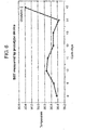
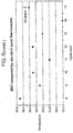
- Figure 6 illustrates the benefit of using a temperature data logger to estimate basal body temperature.
- the first plot in figure 6 is of daily basal body temperature as estimated from data periodically logged overnight while the user was asleep by a prototype data logger in accordance with an embodiment of the present invention. Temperature measurements taken during periods of high movement were ignored and the remaining temperature data from the data logger was processed to remove outlying temperature measurements. An average of the then remaining temperature measurements was taken to eliminate short-term fluctuations in measured temperature.
- the second plot is of body basal temperature over the same days as the first plot estimated using a conventional technique: two measurements were taken by the user with an aural thermometer (a Braun ThermoScope) at 6.30am upon waking.
- the prototype data logger clearly detects the date of ovulation (indicated by the arrows in the plots) whereas it is very difficult to detect using the conventional approach.
- Use of a data logger also removes the need for the user to wake early each morning, take their temperature and note it in a log book.
- Figure 7 shows a circuit diagram of the prototype data logger used to collect the data shown in figure 6 .
- the power source is recharged regularly from the power derived from the electromagnetic field generated by the reader.
- the power source for the device can therefore be relatively small. This combination of small size of the device and wireless recharging during data transmission allows a practical implementation of the device as an implant, or alternatively allows the device to be discretely incorporated into a small adhesive patch which can be affixed to the skin in the same way as a regular sticking plaster or band-aid.
- the data logger includes an integrated circuit containing control logic, timing, measurement, power control, temperature sensing, and wireless communications, which is bonded to a lithium polymer battery for power storage, and the antenna. Because the data logger measures body temperature, the temperature range that the device is exposed to is very narrow and so very low power analogue timing for the sampling frequency is possible with acceptable accuracy using R-C time constants. The change in the power supply over time can also be measured periodically and thus the frequency of measurement can be calibrated during logging. Typically the data logger logs temperature at a predetermined frequency (e.g. every 10 minutes), and records this in memory.
- a predetermined frequency e.g. every 10 minutes
- the system for determining the point of ovulation may comprise a data logger in any of its forms described herein and which is configured to measure temperature, a data reader in any of its forms described herein and a data processor.
- the data logger may be any temperature data logger known in the art capable of passive transmission and with which the data reader is compatible.
- the data logger transmits its stored data to the data reader by passive transmission.
- the data reader and data processor may communicate by any means known in the art.
- the reader device may have a display and user input capability so as to allow the user to view tables or graphs of the data received from the data logger, and/or to allow the user to interact with graphical menu systems.
- the reader device may be connected to a data processor or the data processor may form part of the reader device. It is only important that there is some aspect of the system which is capable of processing the data received from the data logger so as to provide an indication of the point of ovulation in the female user.
- the data processor may simply be a personal computer supporting software arranged to perform the data processing.
- Either the data reader or data processor includes input means for inputting at least one other set of physiological data for the female user.
- the data processor can combine the temperature data with the other sets of physiological data (such as quality of cervical mucus, hormone test results from blood or urine etc) to provide an indication of the point of ovulation in accordance with any of the principles of ovulation detection described above or known in the art.
- the reader device consists of a portable wireless reader with two-way communication with the implant when activated in suitable proximity.
- the user interface may include a number of buttons, to input such data as menstruation days and cervical fluid quality, and a simple LCD display prompting for measurements or indicating parameters such as implant and reader battery charge.
- the user may input any further physiological data directly into the data processor if the data processor is arranged to receive such inputs - this would be convenient for the user if the data processor is a personal computer.
- the reader itself may be capable of estimating the point of ovulation based upon previously recorded data (which may be stored at the reader and/or at the data processor), and is suitably capable of displaying the expected number of days of until the next ovulation to the user.
- the device will preferably not display any information on fertility unless it has recently been in contact with the implant that it is keyed to.
- the reader device may contain a USB port (or other suitable form of wired or wireless connectivity) to allow connection to a personal computer. This allows for (a) recharging of the internal battery of the reader, and/or (b) data transmission to and from the computer for data storage, further processing of the data, data display or simply because the computer performs the temperature data processing in the system.
- a USB port or other suitable form of wired or wireless connectivity
- the device may appear to the computer as a USB "drive" storage device, with the software and manuals for the device available on the drive, thus removing the need for separate software (e.g. CDs) to be carried with the device.
- the software can provide a more extensive user interface, which may be operable to connect to the internet to perform software and firmware updates.
- the user's data can be uploaded over the internet for analysis by third parties, for example medical practitioners.
- the computer interfacing aspect of the reader allows the system to act as a training system for the user in the measurement of more subjective physiological parameters, such as quality of cervical fluid, as the training software can incorporate the thermal history and other data of the user. This reduces the user's reliance on physical teaching by a third party, which is frequently considered invasive or embarrassing.
- the statistical model for ovulation prediction is altered to provide more weighting to these observations. This allows a progressive reduction in the "safety window" around the period of ovulation, during which abstinence should be practiced in order to prevent pregnancy.
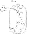
- the data logger described herein may be a human or animal body temperature data logger incorporated into an adhesive wearable patch 407, 503 as shown in figures 4 and 5 .
- the adhesive 411 may be selected from any of the known skin adhesives and is preferably hypoallergenic so as to minimise the risk of an adverse reaction with the skin 401 of the user.
- the patch preferably holds the data logger 403, 501 in a pouch arrangement which allows the data logger to be removed and installed in a new patch when advantageous - for example, when the adhesive loses its stickiness or the user desires a fresh patch.
- Figure 5 shows an opening 507 through which a data logger 501 may be removed and installed. Alternatively the data logger could be sealed in the patch, which can be convenient if the patch and data logger are disposable.
- the patch is roughly circular, approximately 2 cm in diameter and skin-coloured.
- the patch may have a thermally insulating region 405 (such as a soft foam backing) that extends over the part of the data logger which is opposite to the side of the data logger held against the body.
- the patch may have an opening 509 through which a thermally conducting stud 409, 505 of a data logger may protrude and make physical contact with a body to which the patch is affixed. In figure 5 this forms part of the opening 507 through which a data logger may be inserted into the patch.
- the patch (and possibly the data logger shell) is more thermally conductive in the region between the body temperature sensor and the body itself than elsewhere over the patch/shell. This may be achieved through the choice of materials used in the patch/shell and/or by fabricating the patch/shell so the material is thinner in the region over the temperature sensor.
- the patch constructions described above may conveniently be supplied as a sterile, disposable device.
- the data logger may be incorporated into a band (such as may be worn around the arm) or item of clothing, or the data logger may be held in position by an arrangement of straps or bands.
- the band would preferably be worn around the upper arm with the temperature sensor located on the inside of the arm, adjacent to the armpit.
- the data logger is repositioned at the same location (the measurement spot) on the user's body each time the user refits the band.
- the band may therefore have markings so as to aid the user in correctly positioning the data logger held within the band.
- Neoprene which is comfortable to wear for long periods and is a good thermal insulator is a particularly suitable material for the band.
- temperature sensors may be held in a ring in the band. This can help to mitigate the effects of poor rotational positioning of the band by the user.
- a known variation in temperature around the arm (say) about which the band is worn This variation can be measured and stored as a profile for the particular user at the data logger, or more preferably at the data processor to which the temperature measurements are sent for processing.
- the profile allows the temperature measurements from each of the sensors to be later correlated with their position about the arm so as to determine which sensor is closest to the "measurement spot”. It may be further desirable to use the known temperature profile to interpolate between temperature measurements in order to more precisely determine the temperature at the measurement spot each time the band is replaced. These calculations can be performed at the data processor.
- the temperature sensors and aerial are incorporated into the main body of the data logger itself.
- the temperature sensor(s) may be external to the main body of the data logger and wired to the data logger.
- the aerial(s) may be external to the main body of the data logger - perhaps to improve data and power transfer.
- the temperature sensor(s) and/or aerials may be integral to the patch/band and connected to the data logger by wires.
- the data logger itself is encapsulated in a sealed shell to protect the components of the data logger from knocks, liquids and corrosion.
- the data logger can be sterilized in an autoclave.
- the shell has an outer layer of silicone, or another inert material.
- the silicone may be of variable thickness over the shell such that there is a thinner layer of silicone (perhaps 0.1 mm) over the temperature sensor and a thicker layer of silicone (perhaps 0.5 mm) over other areas of the shell.
- the thicker layer of silicone can help to thermally insulate the sensor.
- the silicone may be doped with metal particles over the temperature sensor so as to improve the thermal conductivity of the silicone in that region.
- the silicone or other protective material may preferably be injection moldable and insert moldable, waterproof and/or biocompatible.
- the data logger may have a stud of a highly conductive material (e.g. metal) which protrudes some or all of the way through the data logger shell/silicone so as to improve the thermal coupling between the temperature sensor of the data logger and the body to which it is applied.
- a highly conductive material e.g. metal
- a more accurate correction system may be devised.
- the calibration may be performed in accordance with any of the following methods with the aim of determining the correction function required to yield an approximately constant core body temperature from the data:
- calibration calculations are performed at a data reader or data processor (to which the reader may be connected) as follows:
- Calibration factors may be stored at the data logger (perhaps after being transmitted from the data reader if the calibration calculations are performed at the reader/data processor).
- the thermal properties - or derivative numbers representing said properties - of the data logger shell and/or the patch/band may be stored at the data logger or data reader/processor for use in processing of measured data.
- the thermal properties may be determined during a calibration process or may be available if the data logger shell and/or the patch/band use materials having known properties. Knowledge of these properties can, for example, allow the data processor to calculate a theoretical temperature gradient across the data logger and its enclosures which could be used to extrapolate a core body temperature.
- the relevant physical properties will be stored instead: for example, the acoustic or light transmission properties of the enclosures in which the data logger is incorporated may be stored.
- the calibration principles discussed above apply equally to calibrating measurements of other physical parameters by other types of sensors.
- a data logger having a skin temperature sensor and an ambient temperature sensor may be incorporated into a patch or band as described above, but with an additional opening or region of increased thermal conductivity over the outer temperature sensor so as to better thermally couple that temperature sensor to the external environment.
- a further improvement may be made by utilising three or more temperature sensors located at positions with different thermal parameters, such as local heat capacity and conductivity. For example, if one sensor is on the body side of the device, with low thermal resistance to the body, one sensor is on the external side of the device, with low thermal resistance to the external environment, and one sensor is in the middle of the device, with a comparatively high thermal resistance to either point and a comparatively high local thermal mass, a suitable calibration scheme can be used to provide a more accurate estimate of core temperature.
- the calibration scheme can be pre-set, or can be based on an empirical or adaptive algorithm.
- the data logger configurations described above are not limited to data loggers designed to measure the skin/body temperature of an animal or human and are generally applicable to measuring the temperature or any other physical parameter of any body, whether flora, fauna, machine, rock etc.
- a data logger for a system for determining the point of ovulation in a female that the temperature data from the data logger is combined with data which indicates the activity state of the female.
- female refers to both animal and human females.
- identifying the drop in body temperature that indicates a lowering of "body basal temperature” is difficult without being able to correlate the temperature data to the activity of the female user.
- the basal temperature may be determined from the lowest temperature measured during periods of low movement that last longer than 30 minutes.
- the motion data may be captured at the data logger itself - for instance, by including an accelerometer in the data logger.
- acceleration/vibration data may be logged or knowledge of the force of gravity can be used to measure the "tilt" of the data logger, as is known in the art. As the user moves, the tilt will change, and so movement can be inferred.
- any other means of detecting movement could be used, such as a motion-detecting video camera coupled to the data processor, a pulse sensor (which indirectly indicates when the user is moving/exercising), and a sensor in a bed/mattress which detects movement on the bed (e.g. the user rolling over).
- Preferably movement of the user is measured at the data logger itself.
- the data logger can be set not to log any temperature data.
- the movement data itself need not therefore be logged at the data logger - it is used to determine when to measure and log temperature and when not to do so. This makes efficient use of the memory at the data logger.
- both movement and temperature may be logged at the data logger and the data processor can subsequently combine these data sets in order to determine which portions of temperature data are likely to correlate closely to the true core body temperature of the user and which portions of data are likely to be less reliable.
- Performing this at the data processor allows a more sophisticated approach to be taken. For example, more complex algorithms can be applied that allow short periods of motion to be overlooked (such as the user rolling over in their sleep) in determining when a relatively extended period of low movement occurred in which good quality temperature measurements are likely to have been taken. Those temperature measurements taken during relatively extended periods of low movement are preferably used in determining the basal body temperature (or some analogue thereof) and the remaining data may be discarded.
- temperature data from a data logger may be processed at a data processor in combination with movement information for the user (from either the data logger or external measurements) will now be described.
- This processing is preferably performed on the data of each day (or night) for which there is data at a time so as to provide an estimate of the daily basal temperature of the user.
- the temperature data may be limited to those measurements taken when the user is likely to be asleep or at rest by only processing temperature data taken between certain hours (e.g. 11 pm to 6am). Or the user could simply only wear the data logger (as a patch, arm band etc.) when sleeping.
- basal body temperature can be determined from temperature data taken while the user is sleeping. However, sometimes the user will only be able to sleep for a short period, or sometimes the temperature data is of poor quality for part of the sleep period. In these cases it is possible to estimate the basal body temperature of the user by extrapolating the slow decrease in body temperature that occurs during the sleep of the user so as to form an estimate of the minimum body temperature the user would have reached had they been able to sleep for a sufficient length of time (or had there been temperature data of a good enough quality). This minimum can be estimated using techniques known in the art from the slope of the temperature-time curve: for example, the rate of change of the slop of the curve can be used to anticipate when the body temperature minimum occurs.
- the estimate can be improved by comparing the incomplete temperature data with temperature-time curves taken during previous sleep periods: for example, knowledge of how long it typically takes for the user's body temperature to reach its minimum can be used to anticipate when that minimum occurs for a given initial temperature and slope of the temperature-time curve.
- a data logger in accordance with the present invention can have any number of inputs, each of which may be an input from any kind of sensor (such as a temperature sensor, accelerometer).
- the data logger Upon polling by a data reader device the data logger transmits one or more of the sensor data sets.
- the data logger may transmit the data to the reader in any of a number of ways, including: transmitting only those data sets requested by the reader, transmitting the data sets in a predetermined order, and transmitting the measurements in the order (or reverse order) in which they were taken.
- the data logger might have a programmable data logging interval, which is set when the patch is first applied to the patient (by means of a command from the data reader to the data logger, for example). The data logger may then log data at the specified intervals until instructed to stop (or until the battery dies). In some embodiments the data logger stores a timestamp with each measurement, or stores a timestamp each time the data logger (re-)commences logging.
- All the embodiments of a data logger described above in relation to a data logger for use in a system for determining the point of ovulation in a female are generally applicable to data logger devices which may have any number of applications and sensor types.
- the temperature data stored at a data logger represents a thermal history of the body to which it is attached over time. For some applications, such as determining the point of ovulation in a female (human or animal), it is not necessary to measure body temperature at every point throughout the day. In this case it is convenient for the user for the data logger to be incorporated into a band which is worn about the upper arm, but which may be removed for showering or playing sports. In these cases, the data logger can stop logging when (for example) the temperature drops below a certain level (because the sensor is no longer in contact with the skin), or when a button is pressed on the data logger/armband, or when it receives a command from the data reader device, to give a few examples.
- a (possibly disposable) patch configuration is useful in medical applications, when it is important to have complete and uninterrupted temperature measurements of a patient's body temperature.
- High resolution (both in temperature precision and in frequency of measurement) temperature data is of use in diagnosing a number of medical conditions, for example certain types of infections, hypothermia or pyrexia. Having access to a complete temperature history stored at a data logging device worn by the patient can help a physician to more quickly reach an accurate diagnosis.
Landscapes
- Health & Medical Sciences (AREA)
- Life Sciences & Earth Sciences (AREA)
- Engineering & Computer Science (AREA)
- Public Health (AREA)
- General Health & Medical Sciences (AREA)
- Animal Behavior & Ethology (AREA)
- Veterinary Medicine (AREA)
- Pathology (AREA)
- Biomedical Technology (AREA)
- Heart & Thoracic Surgery (AREA)
- Medical Informatics (AREA)
- Molecular Biology (AREA)
- Surgery (AREA)
- Biophysics (AREA)
- Physics & Mathematics (AREA)
- Computer Networks & Wireless Communication (AREA)
- Physiology (AREA)
- Immunology (AREA)
- Vascular Medicine (AREA)
- Measuring And Recording Apparatus For Diagnosis (AREA)
- Measurement Of The Respiration, Hearing Ability, Form, And Blood Characteristics Of Living Organisms (AREA)
- Measuring Temperature Or Quantity Of Heat (AREA)
- Recording Measured Values (AREA)
- Arrangements For Transmission Of Measured Signals (AREA)
Priority Applications (1)
| Application Number | Priority Date | Filing Date | Title |
|---|---|---|---|
| PL07858836T PL2020923T5 (pl) | 2006-05-04 | 2007-05-04 | Pomiary in situ parametrów fizycznych |
Applications Claiming Priority (2)
| Application Number | Priority Date | Filing Date | Title |
|---|---|---|---|
| GBGB0608829.8A GB0608829D0 (en) | 2006-05-04 | 2006-05-04 | In-situ measurement of physical parameters |
| PCT/IB2007/001822 WO2008035151A2 (en) | 2006-05-04 | 2007-05-04 | In-situ measurement of phyisical parameters |
Publications (3)
| Publication Number | Publication Date |
|---|---|
| EP2020923A2 EP2020923A2 (en) | 2009-02-11 |
| EP2020923B1 EP2020923B1 (en) | 2013-05-01 |
| EP2020923B2 true EP2020923B2 (en) | 2019-05-15 |
Family
ID=36603924
Family Applications (1)
| Application Number | Title | Priority Date | Filing Date |
|---|---|---|---|
| EP07858836.5A Active EP2020923B2 (en) | 2006-05-04 | 2007-05-04 | In-situ measurement of physical parameters |
Country Status (11)
| Country | Link |
|---|---|
| US (1) | US8540644B2 (enExample) |
| EP (1) | EP2020923B2 (enExample) |
| JP (1) | JP5256191B2 (enExample) |
| CN (1) | CN101460100B (enExample) |
| BR (1) | BRPI0711559A2 (enExample) |
| ES (1) | ES2414611T5 (enExample) |
| GB (1) | GB0608829D0 (enExample) |
| MX (1) | MX2008014060A (enExample) |
| PL (1) | PL2020923T5 (enExample) |
| RU (1) | RU2008147709A (enExample) |
| WO (1) | WO2008035151A2 (enExample) |
Families Citing this family (203)
| Publication number | Priority date | Publication date | Assignee | Title |
|---|---|---|---|---|
| EP1578262A4 (en) | 2002-12-31 | 2007-12-05 | Therasense Inc | CONTINUOUS BLOOD SUGAR MONITORING SYSTEM AND USE METHOD |
| US7587287B2 (en) | 2003-04-04 | 2009-09-08 | Abbott Diabetes Care Inc. | Method and system for transferring analyte test data |
| US7679407B2 (en) | 2003-04-28 | 2010-03-16 | Abbott Diabetes Care Inc. | Method and apparatus for providing peak detection circuitry for data communication systems |
| KR101207442B1 (ko) * | 2003-12-15 | 2012-12-03 | 가부시키가이샤 한도오따이 에네루기 켄큐쇼 | 박막 집적회로장치의 제조방법, 비접촉형 박막 집적회로장치 및 그 제조 방법, 비접촉형 박막 집적회로 장치를 가지는 아이디 태그 및 동전 |
| WO2005089103A2 (en) | 2004-02-17 | 2005-09-29 | Therasense, Inc. | Method and system for providing data communication in continuous glucose monitoring and management system |
| WO2005119524A2 (en) | 2004-06-04 | 2005-12-15 | Therasense, Inc. | Diabetes care host-client architecture and data management system |
| US9788771B2 (en) | 2006-10-23 | 2017-10-17 | Abbott Diabetes Care Inc. | Variable speed sensor insertion devices and methods of use |
| US8029441B2 (en) | 2006-02-28 | 2011-10-04 | Abbott Diabetes Care Inc. | Analyte sensor transmitter unit configuration for a data monitoring and management system |
| US7545272B2 (en) | 2005-02-08 | 2009-06-09 | Therasense, Inc. | RF tag on test strips, test strip vials and boxes |
| US9198608B2 (en) | 2005-04-28 | 2015-12-01 | Proteus Digital Health, Inc. | Communication system incorporated in a container |
| US8836513B2 (en) | 2006-04-28 | 2014-09-16 | Proteus Digital Health, Inc. | Communication system incorporated in an ingestible product |
| EP3827747A1 (en) | 2005-04-28 | 2021-06-02 | Otsuka Pharmaceutical Co., Ltd. | Pharma-informatics system |
| US8912908B2 (en) | 2005-04-28 | 2014-12-16 | Proteus Digital Health, Inc. | Communication system with remote activation |
| US8802183B2 (en) | 2005-04-28 | 2014-08-12 | Proteus Digital Health, Inc. | Communication system with enhanced partial power source and method of manufacturing same |
| US8730031B2 (en) | 2005-04-28 | 2014-05-20 | Proteus Digital Health, Inc. | Communication system using an implantable device |
| US7768408B2 (en) | 2005-05-17 | 2010-08-03 | Abbott Diabetes Care Inc. | Method and system for providing data management in data monitoring system |
| JP2009507224A (ja) | 2005-08-31 | 2009-02-19 | ユニヴァーシティー オブ ヴァージニア パテント ファンデーション | 連続グルコースセンサの精度の改善 |
| US8547248B2 (en) | 2005-09-01 | 2013-10-01 | Proteus Digital Health, Inc. | Implantable zero-wire communications system |
| US7583190B2 (en) | 2005-10-31 | 2009-09-01 | Abbott Diabetes Care Inc. | Method and apparatus for providing data communication in data monitoring and management systems |
| FR2895667B3 (fr) * | 2006-01-05 | 2008-04-04 | Rene Vinci | Detecteur de fecondite pour mammiferes |
| US8478557B2 (en) | 2009-07-31 | 2013-07-02 | Abbott Diabetes Care Inc. | Method and apparatus for providing analyte monitoring system calibration accuracy |
| US9392969B2 (en) | 2008-08-31 | 2016-07-19 | Abbott Diabetes Care Inc. | Closed loop control and signal attenuation detection |
| US7620438B2 (en) | 2006-03-31 | 2009-11-17 | Abbott Diabetes Care Inc. | Method and system for powering an electronic device |
| US7801582B2 (en) | 2006-03-31 | 2010-09-21 | Abbott Diabetes Care Inc. | Analyte monitoring and management system and methods therefor |
| US9675290B2 (en) | 2012-10-30 | 2017-06-13 | Abbott Diabetes Care Inc. | Sensitivity calibration of in vivo sensors used to measure analyte concentration |
| US9326709B2 (en) | 2010-03-10 | 2016-05-03 | Abbott Diabetes Care Inc. | Systems, devices and methods for managing glucose levels |
| US8219173B2 (en) | 2008-09-30 | 2012-07-10 | Abbott Diabetes Care Inc. | Optimizing analyte sensor calibration |
| EP2013829A4 (en) | 2006-05-02 | 2010-07-07 | Proteus Biomedical Inc | PERSONALIZED THERAPEUTIC REGIMES FOR A PATIENT |
| GB0617451D0 (enExample) | 2006-09-05 | 2006-10-18 | Medical Prediction Ltd | |
| EP2087589B1 (en) | 2006-10-17 | 2011-11-23 | Proteus Biomedical, Inc. | Low voltage oscillator for medical devices |
| JP5916277B2 (ja) | 2006-10-25 | 2016-05-11 | プロテウス デジタル ヘルス, インコーポレイテッド | 摂取可能な制御活性化識別子 |
| EP2069004A4 (en) | 2006-11-20 | 2014-07-09 | Proteus Digital Health Inc | PERSONAL HEALTH SIGNAL RECEIVERS WITH ACTIVE SIGNAL PROCESSING |
| CN101686800A (zh) | 2007-02-01 | 2010-03-31 | 普罗秋斯生物医学公司 | 可摄入事件标记器系统 |
| AU2008216170B2 (en) | 2007-02-14 | 2012-07-26 | Otsuka Pharmaceutical Co., Ltd. | In-body power source having high surface area electrode |
| US20080199894A1 (en) | 2007-02-15 | 2008-08-21 | Abbott Diabetes Care, Inc. | Device and method for automatic data acquisition and/or detection |
| US8123686B2 (en) | 2007-03-01 | 2012-02-28 | Abbott Diabetes Care Inc. | Method and apparatus for providing rolling data in communication systems |
| WO2008112578A1 (en) | 2007-03-09 | 2008-09-18 | Proteus Biomedical, Inc. | In-body device having a deployable antenna |
| WO2008112577A1 (en) | 2007-03-09 | 2008-09-18 | Proteus Biomedical, Inc. | In-body device having a multi-directional transmitter |
| WO2008130898A1 (en) | 2007-04-14 | 2008-10-30 | Abbott Diabetes Care, Inc. | Method and apparatus for providing data processing and control in medical communication system |
| ES2461090T3 (es) | 2007-04-14 | 2014-05-16 | Abbott Diabetes Care Inc. | Procedimiento y aparato para proporcionar tratamiento y control de datos en un sistema de comunicación médica |
| WO2008128210A1 (en) | 2007-04-14 | 2008-10-23 | Abbott Diabetes Care, Inc. | Method and apparatus for providing data processing and control in medical communication system |
| EP3741291A1 (en) | 2007-04-14 | 2020-11-25 | Abbott Diabetes Care, Inc. | Method and apparatus for providing data processing and control in medical communication system |
| EP2146624B1 (en) | 2007-04-14 | 2020-03-25 | Abbott Diabetes Care Inc. | Method and apparatus for providing data processing and control in medical communication system |
| US8665091B2 (en) | 2007-05-08 | 2014-03-04 | Abbott Diabetes Care Inc. | Method and device for determining elapsed sensor life |
| US8461985B2 (en) | 2007-05-08 | 2013-06-11 | Abbott Diabetes Care Inc. | Analyte monitoring system and methods |
| US8456301B2 (en) | 2007-05-08 | 2013-06-04 | Abbott Diabetes Care Inc. | Analyte monitoring system and methods |
| US7928850B2 (en) | 2007-05-08 | 2011-04-19 | Abbott Diabetes Care Inc. | Analyte monitoring system and methods |
| US8239166B2 (en) | 2007-05-14 | 2012-08-07 | Abbott Diabetes Care Inc. | Method and apparatus for providing data processing and control in a medical communication system |
| US8103471B2 (en) | 2007-05-14 | 2012-01-24 | Abbott Diabetes Care Inc. | Method and apparatus for providing data processing and control in a medical communication system |
| US8600681B2 (en) | 2007-05-14 | 2013-12-03 | Abbott Diabetes Care Inc. | Method and apparatus for providing data processing and control in a medical communication system |
| US8560038B2 (en) | 2007-05-14 | 2013-10-15 | Abbott Diabetes Care Inc. | Method and apparatus for providing data processing and control in a medical communication system |
| US10002233B2 (en) | 2007-05-14 | 2018-06-19 | Abbott Diabetes Care Inc. | Method and apparatus for providing data processing and control in a medical communication system |
| US9125548B2 (en) | 2007-05-14 | 2015-09-08 | Abbott Diabetes Care Inc. | Method and apparatus for providing data processing and control in a medical communication system |
| US8260558B2 (en) | 2007-05-14 | 2012-09-04 | Abbott Diabetes Care Inc. | Method and apparatus for providing data processing and control in a medical communication system |
| US8444560B2 (en) | 2007-05-14 | 2013-05-21 | Abbott Diabetes Care Inc. | Method and apparatus for providing data processing and control in a medical communication system |
| US8540632B2 (en) | 2007-05-24 | 2013-09-24 | Proteus Digital Health, Inc. | Low profile antenna for in body device |
| EP3533387A3 (en) | 2007-06-21 | 2019-11-13 | Abbott Diabetes Care, Inc. | Health management devices and methods |
| US8617069B2 (en) | 2007-06-21 | 2013-12-31 | Abbott Diabetes Care Inc. | Health monitor |
| US8160900B2 (en) | 2007-06-29 | 2012-04-17 | Abbott Diabetes Care Inc. | Analyte monitoring and management device and method to analyze the frequency of user interaction with the device |
| US8801636B2 (en) * | 2007-07-19 | 2014-08-12 | Cardiac Pacemakers, Inc. | Method and apparatus for determining wellness based on decubitus posture |
| US8834366B2 (en) | 2007-07-31 | 2014-09-16 | Abbott Diabetes Care Inc. | Method and apparatus for providing analyte sensor calibration |
| US9046919B2 (en) | 2007-08-20 | 2015-06-02 | Hmicro, Inc. | Wearable user interface device, system, and method of use |
| US8926509B2 (en) | 2007-08-24 | 2015-01-06 | Hmicro, Inc. | Wireless physiological sensor patches and systems |
| US8961412B2 (en) | 2007-09-25 | 2015-02-24 | Proteus Digital Health, Inc. | In-body device with virtual dipole signal amplification |
| WO2009055423A1 (en) | 2007-10-24 | 2009-04-30 | Hmicro, Inc. | Low power radiofrequency (rf) communication systems for secure wireless patch initialization and methods of use |
| US8611319B2 (en) | 2007-10-24 | 2013-12-17 | Hmicro, Inc. | Methods and apparatus to retrofit wired healthcare and fitness systems for wireless operation |
| US9314261B2 (en) | 2007-12-03 | 2016-04-19 | Covidien Ag | Battery-powered hand-held ultrasonic surgical cautery cutting device |
| US20090164239A1 (en) | 2007-12-19 | 2009-06-25 | Abbott Diabetes Care, Inc. | Dynamic Display Of Glucose Information |
| CA2717862C (en) | 2008-03-05 | 2016-11-22 | Proteus Biomedical, Inc. | Multi-mode communication ingestible event markers and systems, and methods of using the same |
| CN102084237B (zh) * | 2008-05-27 | 2015-02-18 | 肯·肯有限公司 | 用于确定粘液的流变性质的设备和方法 |
| US7826382B2 (en) | 2008-05-30 | 2010-11-02 | Abbott Diabetes Care Inc. | Close proximity communication device and methods |
| SG195535A1 (en) | 2008-07-08 | 2013-12-30 | Proteus Digital Health Inc | Ingestible event marker data framework |
| US8231556B2 (en) | 2008-07-11 | 2012-07-31 | Medtronic, Inc. | Obtaining baseline patient information |
| AU2009281876B2 (en) | 2008-08-13 | 2014-05-22 | Proteus Digital Health, Inc. | Ingestible circuitry |
| JP5411943B2 (ja) | 2008-11-13 | 2014-02-12 | プロテウス デジタル ヘルス, インコーポレイテッド | 摂取可能な治療起動装置システムおよび方法 |
| CA2746650A1 (en) | 2008-12-11 | 2010-06-17 | Proteus Biomedical, Inc. | Evaluation of gastrointestinal function using portable electroviscerography systems and methods of using the same |
| US9659423B2 (en) | 2008-12-15 | 2017-05-23 | Proteus Digital Health, Inc. | Personal authentication apparatus system and method |
| TWI503101B (zh) | 2008-12-15 | 2015-10-11 | Proteus Digital Health Inc | 與身體有關的接收器及其方法 |
| US9439566B2 (en) | 2008-12-15 | 2016-09-13 | Proteus Digital Health, Inc. | Re-wearable wireless device |
| MY153758A (en) | 2009-01-06 | 2015-03-13 | Proteus Digital Health Inc | Pharmaceutical dosages delivery system |
| CN102341031A (zh) | 2009-01-06 | 2012-02-01 | 普罗秋斯生物医学公司 | 摄取相关的生物反馈和个人化医学治疗方法和系统 |
| US9402544B2 (en) | 2009-02-03 | 2016-08-02 | Abbott Diabetes Care Inc. | Analyte sensor and apparatus for insertion of the sensor |
| WO2010098954A2 (en) | 2009-02-27 | 2010-09-02 | Body Surface Translations, Inc. | Estimating physical parameters using three dimensional representations |
| WO2010111403A2 (en) | 2009-03-25 | 2010-09-30 | Proteus Biomedical, Inc. | Probablistic pharmacokinetic and pharmacodynamic modeling |
| BR122013009559A2 (pt) | 2009-04-28 | 2019-08-06 | Proteus Digital Health, Inc. | Marcadores de evento de ingerível altamente confiável e métodos para usar os mesmos |
| US9226701B2 (en) | 2009-04-28 | 2016-01-05 | Abbott Diabetes Care Inc. | Error detection in critical repeating data in a wireless sensor system |
| WO2010127187A1 (en) | 2009-04-29 | 2010-11-04 | Abbott Diabetes Care Inc. | Method and system for providing data communication in continuous glucose monitoring and management system |
| US9149423B2 (en) | 2009-05-12 | 2015-10-06 | Proteus Digital Health, Inc. | Ingestible event markers comprising an ingestible component |
| US9184490B2 (en) | 2009-05-29 | 2015-11-10 | Abbott Diabetes Care Inc. | Medical device antenna systems having external antenna configurations |
| US8558563B2 (en) | 2009-08-21 | 2013-10-15 | Proteus Digital Health, Inc. | Apparatus and method for measuring biochemical parameters |
| WO2011026148A1 (en) | 2009-08-31 | 2011-03-03 | Abbott Diabetes Care Inc. | Analyte monitoring system and methods for managing power and noise |
| CN102473276B (zh) | 2009-08-31 | 2016-04-13 | 雅培糖尿病护理公司 | 医疗装置及方法 |
| WO2011041531A1 (en) | 2009-09-30 | 2011-04-07 | Abbott Diabetes Care Inc. | Interconnect for on-body analyte monitoring device |
| TWI517050B (zh) | 2009-11-04 | 2016-01-11 | 普羅托斯數位健康公司 | 供應鏈管理之系統 |
| UA109424C2 (uk) | 2009-12-02 | 2015-08-25 | Фармацевтичний продукт, фармацевтична таблетка з електронним маркером і спосіб виготовлення фармацевтичної таблетки | |
| US8325048B2 (en) | 2009-12-08 | 2012-12-04 | Kimberly-Clark Worldwide, Inc. | Thermal stress indicator |
| KR101798128B1 (ko) | 2010-02-01 | 2017-11-16 | 프로테우스 디지털 헬스, 인코포레이티드 | 데이터 수집 시스템 |
| RU2012143791A (ru) | 2010-04-07 | 2014-05-20 | Проутьюс Диджитал Хэлс, Инк. | Миниатюрное проглатываемое устройство |
| GB2479937B (en) * | 2010-04-30 | 2014-02-19 | Samsung Electronics Co Ltd | Management of storage of measurement data |
| CA2835311A1 (en) | 2010-05-07 | 2011-11-10 | Conscious Cycles Llc | System for tracking female fertility |
| TWI557672B (zh) | 2010-05-19 | 2016-11-11 | 波提亞斯數位康健公司 | 用於從製造商跟蹤藥物直到患者之電腦系統及電腦實施之方法、用於確認將藥物給予患者的設備及方法、患者介面裝置 |
| US20110295080A1 (en) * | 2010-05-30 | 2011-12-01 | Ralink Technology Corporation | Physiology Condition Detection Device and the System Thereof |
| US8635046B2 (en) | 2010-06-23 | 2014-01-21 | Abbott Diabetes Care Inc. | Method and system for evaluating analyte sensor response characteristics |
| US11213226B2 (en) | 2010-10-07 | 2022-01-04 | Abbott Diabetes Care Inc. | Analyte monitoring devices and methods |
| WO2012052599A1 (en) | 2010-10-22 | 2012-04-26 | Upm Rfid Oy | Advanced functionality of remote-access devices |
| JP2014504902A (ja) | 2010-11-22 | 2014-02-27 | プロテウス デジタル ヘルス, インコーポレイテッド | 医薬品を有する摂取可能なデバイス |
| DE102010062567A1 (de) * | 2010-12-07 | 2012-06-14 | Robert Bosch Gmbh | Verfahren, Sensormodul und System zur Datenübertragung |
| CA3277222A1 (en) | 2011-02-28 | 2025-10-30 | Abbott Diabetes Care Inc | Devices, systems, and methods associated with analyte monitoring devices and devices incorporating the same |
| US10136845B2 (en) | 2011-02-28 | 2018-11-27 | Abbott Diabetes Care Inc. | Devices, systems, and methods associated with analyte monitoring devices and devices incorporating the same |
| US9439599B2 (en) | 2011-03-11 | 2016-09-13 | Proteus Digital Health, Inc. | Wearable personal body associated device with various physical configurations |
| CA3022252C (en) * | 2011-04-15 | 2020-09-22 | Covidien Ag | Battery powered hand-held ultrasonic surgical cautery cutting device |
| WO2012174563A1 (en) | 2011-06-16 | 2012-12-20 | Abbott Diabetes Care Inc. | Temperature-compensated analyte monitoring devices, systems, and methods thereof |
| US9756874B2 (en) | 2011-07-11 | 2017-09-12 | Proteus Digital Health, Inc. | Masticable ingestible product and communication system therefor |
| WO2015112603A1 (en) | 2014-01-21 | 2015-07-30 | Proteus Digital Health, Inc. | Masticable ingestible product and communication system therefor |
| RU2014106126A (ru) | 2011-07-21 | 2015-08-27 | Протеус Диджитал Хелс, Инк. | Устройство, система и способ мобильной связи |
| US9622691B2 (en) | 2011-10-31 | 2017-04-18 | Abbott Diabetes Care Inc. | Model based variable risk false glucose threshold alarm prevention mechanism |
| US9069536B2 (en) | 2011-10-31 | 2015-06-30 | Abbott Diabetes Care Inc. | Electronic devices having integrated reset systems and methods thereof |
| AT512101A2 (de) * | 2011-10-31 | 2013-05-15 | Seibersdorf Labor Gmbh | Messeinrichtung zur glukosemessung |
| JP6443802B2 (ja) | 2011-11-07 | 2018-12-26 | アボット ダイアベティス ケア インコーポレイテッドAbbott Diabetes Care Inc. | 分析物モニタリング装置および方法 |
| US9235683B2 (en) | 2011-11-09 | 2016-01-12 | Proteus Digital Health, Inc. | Apparatus, system, and method for managing adherence to a regimen |
| US20130131541A1 (en) * | 2011-11-23 | 2013-05-23 | Eternal Electronics Limited | Cell phone app for coupling a cell phone to a basal body temperature thermometer for predicting ovulation |
| US8710993B2 (en) | 2011-11-23 | 2014-04-29 | Abbott Diabetes Care Inc. | Mitigating single point failure of devices in an analyte monitoring system and methods thereof |
| US9317656B2 (en) | 2011-11-23 | 2016-04-19 | Abbott Diabetes Care Inc. | Compatibility mechanisms for devices in a continuous analyte monitoring system and methods thereof |
| US8834389B2 (en) | 2011-11-25 | 2014-09-16 | Tepsync | Temperature based fertility monitoring system and related method |
| US9636509B2 (en) | 2012-01-27 | 2017-05-02 | Medtronic, Inc. | Retrieval of information from an implantable medical device |
| JP5988195B2 (ja) * | 2012-03-29 | 2016-09-07 | パナソニックIpマネジメント株式会社 | 機器制御装置、機器制御システムおよびプログラム |
| US9271897B2 (en) | 2012-07-23 | 2016-03-01 | Proteus Digital Health, Inc. | Techniques for manufacturing ingestible event markers comprising an ingestible component |
| WO2014035732A1 (en) | 2012-08-30 | 2014-03-06 | Abbot Diabetes Care Inc. | Dropout detection in continuous analyte monitoring data during data excursions |
| US9968306B2 (en) | 2012-09-17 | 2018-05-15 | Abbott Diabetes Care Inc. | Methods and apparatuses for providing adverse condition notification with enhanced wireless communication range in analyte monitoring systems |
| WO2014052136A1 (en) | 2012-09-26 | 2014-04-03 | Abbott Diabetes Care Inc. | Method and apparatus for improving lag correction during in vivo measurement of analyte concentration with analyte concentration variability and range data |
| US9477993B2 (en) | 2012-10-14 | 2016-10-25 | Ari M Frank | Training a predictor of emotional response based on explicit voting on content and eye tracking to verify attention |
| US9104467B2 (en) | 2012-10-14 | 2015-08-11 | Ari M Frank | Utilizing eye tracking to reduce power consumption involved in measuring affective response |
| BR112015008434A2 (pt) | 2012-10-18 | 2017-07-04 | Proteus Digital Health Inc | aparelho, sistema e método para otimizar adaptativamente a dissipação de potência e a potência de radiodifusão em uma fonte de alimentação para um dispositivo de comunicação |
| US9386932B2 (en) | 2012-10-29 | 2016-07-12 | Microsoft Technology Licensing, Llc | Wearable personal information system |
| WO2014070254A1 (en) | 2012-11-01 | 2014-05-08 | Blue Spark Technologies, Inc. | Body temperature logging patch |
| US10244986B2 (en) | 2013-01-23 | 2019-04-02 | Avery Dennison Corporation | Wireless sensor patches and methods of manufacturing |
| TWI659994B (zh) | 2013-01-29 | 2019-05-21 | 美商普羅托斯數位健康公司 | 高度可膨脹之聚合型薄膜及包含彼之組成物 |
| US9238144B2 (en) | 2013-03-14 | 2016-01-19 | Neuropace, Inc. | Optimizing data retrieval from an active implantable medical device |
| JP6498177B2 (ja) | 2013-03-15 | 2019-04-10 | プロテウス デジタル ヘルス, インコーポレイテッド | 本人認証装置システムおよび方法 |
| WO2014197402A1 (en) | 2013-06-04 | 2014-12-11 | Proteus Digital Health, Inc. | System, apparatus and methods for data collection and assessing outcomes |
| US10433773B1 (en) | 2013-03-15 | 2019-10-08 | Abbott Diabetes Care Inc. | Noise rejection methods and apparatus for sparsely sampled analyte sensor data |
| US9474475B1 (en) | 2013-03-15 | 2016-10-25 | Abbott Diabetes Care Inc. | Multi-rate analyte sensor data collection with sample rate configurable signal processing |
| US10175376B2 (en) | 2013-03-15 | 2019-01-08 | Proteus Digital Health, Inc. | Metal detector apparatus, system, and method |
| US10076285B2 (en) | 2013-03-15 | 2018-09-18 | Abbott Diabetes Care Inc. | Sensor fault detection using analyte sensor data pattern comparison |
| CN103142255B (zh) * | 2013-03-19 | 2014-12-17 | 褚真威 | 一种妇女排卵期电子检测仪及检测方法 |
| US9654847B2 (en) | 2013-04-30 | 2017-05-16 | Sca Hygiene Products Ab | Monitoring and displaying an absorption state of an absorbent article |
| JP2014233585A (ja) * | 2013-06-05 | 2014-12-15 | 日本電信電話株式会社 | 体温測定装置、方法及びプログラム |
| US9796576B2 (en) | 2013-08-30 | 2017-10-24 | Proteus Digital Health, Inc. | Container with electronically controlled interlock |
| EP3047618B1 (en) | 2013-09-20 | 2023-11-08 | Otsuka Pharmaceutical Co., Ltd. | Methods, devices and systems for receiving and decoding a signal in the presence of noise using slices and warping |
| JP2016537924A (ja) | 2013-09-24 | 2016-12-01 | プロテウス デジタル ヘルス, インコーポレイテッド | 事前に正確に把握されていない周波数において受信された電磁信号に関する使用のための方法および装置 |
| US10084880B2 (en) | 2013-11-04 | 2018-09-25 | Proteus Digital Health, Inc. | Social media networking based on physiologic information |
| US10060802B1 (en) * | 2013-12-02 | 2018-08-28 | Summer Merie Ragosta | Intelligent digital thermometer |
| US20150157435A1 (en) * | 2013-12-06 | 2015-06-11 | PegaSense, Inc. | Equine fitness monitor |
| US9664571B2 (en) * | 2013-12-27 | 2017-05-30 | Microchip Technology Incorporated | Digital temperature sensor with integrated timer and burst mode |
| JP6303630B2 (ja) * | 2014-03-10 | 2018-04-04 | Tdk株式会社 | 排卵日推定装置、排卵日推定方法及び排卵日推定プログラム |
| EP3125761B1 (en) | 2014-03-30 | 2020-09-30 | Abbott Diabetes Care Inc. | Method and apparatus for determining meal start and peak events in analyte monitoring systems |
| DE102014006726A1 (de) * | 2014-05-08 | 2015-11-12 | Infineon Technologies Ag | Blutdrucksensor |
| DE102014006999A1 (de) | 2014-05-13 | 2015-11-19 | Swissmed Mobile Ag | Vorrichtung und Verfahren zur In-Vivo Erfassung von Patientendaten und Übertragung an eine Datenverarbeitungseinrichtung |
| US10575829B2 (en) | 2014-09-03 | 2020-03-03 | Earlysense Ltd. | Menstrual state monitoring |
| GB2532919B (en) * | 2014-10-24 | 2019-05-15 | Cambridge temperature concepts ltd | Monitoring physiology |
| US10467382B2 (en) * | 2014-11-14 | 2019-11-05 | Brazen Incorporated | Conceivable basal body temperatures and menstrual cycle |
| EP3226750A4 (en) * | 2014-12-05 | 2018-07-04 | Lifecycle Technologies Pty Ltd | Method and system for improving a physiological response |
| US20190110692A1 (en) * | 2014-12-23 | 2019-04-18 | James Pardey | Processing a physical signal |
| US9693689B2 (en) | 2014-12-31 | 2017-07-04 | Blue Spark Technologies, Inc. | Body temperature logging patch |
| CN104602614B (zh) * | 2015-01-15 | 2017-03-29 | 深圳市三木智能技术有限公司 | 便携移动医疗终端的数据采集运算方法及系统 |
| CA3254799A1 (en) | 2015-07-10 | 2025-04-12 | Abbott Diabetes Care Inc | System, device and method of dynamic glucose profile response to physiological parameters |
| US11051543B2 (en) | 2015-07-21 | 2021-07-06 | Otsuka Pharmaceutical Co. Ltd. | Alginate on adhesive bilayer laminate film |
| DE102015010189A1 (de) * | 2015-08-04 | 2017-02-09 | Infineon Technologies Ag | Körperparameterüberwachungsvorrichtung |
| KR101695568B1 (ko) * | 2015-09-30 | 2017-01-11 | 고려대학교 산학협력단 | 다기능 센서모듈 |
| WO2017122199A1 (en) | 2016-01-12 | 2017-07-20 | Tempdrop Ltd | System and method for determining physiological condition based on variations in body temperature |
| US11328152B2 (en) * | 2019-06-17 | 2022-05-10 | Pixart Imaging Inc. | Recognition system employing thermal sensor |
| WO2018018034A1 (en) | 2016-07-22 | 2018-01-25 | Proteus Digital Health, Inc. | Electromagnetic sensing and detection of ingestible event markers |
| US10582854B2 (en) * | 2016-08-05 | 2020-03-10 | Vital Connect, Inc. | Temperature sensor for measuring thermistor resistance |
| EP3300662B1 (en) * | 2016-09-30 | 2022-08-17 | Nokia Technologies Oy | Determining an intimate activity by a detection device |
| JP2019535377A (ja) | 2016-10-26 | 2019-12-12 | プロテウス デジタル ヘルス, インコーポレイテッド | 摂取可能なイベントマーカを有するカプセルの製造方法 |
| US10856741B2 (en) * | 2016-12-14 | 2020-12-08 | Vital Connect, Inc. | Core body temperature detection device |
| CN110461217B (zh) | 2017-01-23 | 2022-09-16 | 雅培糖尿病护理公司 | 用于分析物传感器插入的系统、装置和方法 |
| CN108344524B (zh) * | 2017-01-24 | 2021-08-06 | 维瓦灵克有限公司 | 一种用于测量温度及电信号的可穿戴贴片 |
| US11504054B2 (en) | 2017-03-07 | 2022-11-22 | University Of Southampton | Intra-uterine monitoring system |
| WO2018175489A1 (en) | 2017-03-21 | 2018-09-27 | Abbott Diabetes Care Inc. | Methods, devices and system for providing diabetic condition diagnosis and therapy |
| JP6858616B2 (ja) * | 2017-03-29 | 2021-04-14 | 旭化成ホームズ株式会社 | 生体情報管理システム、生体情報管理装置、及び生体情報管理方法 |
| GB2561193B (en) * | 2017-04-04 | 2020-09-23 | ONiO AS | Sensor system and method for continuous and wireless monitoring and analysis of temperature in organisms |
| CA3063363A1 (en) | 2017-05-10 | 2018-11-15 | Humane, LLC | System and apparatus for fertility and hormonal cycle awareness |
| US10849501B2 (en) | 2017-08-09 | 2020-12-01 | Blue Spark Technologies, Inc. | Body temperature logging patch |
| CN109394173A (zh) * | 2017-08-18 | 2019-03-01 | 同济大学 | 一种智能治疗器的控制方法及系统 |
| WO2019053719A1 (en) * | 2017-09-17 | 2019-03-21 | Earlysense Ltd. | Apparatus and methods for monitoring a subject |
| US20190183095A1 (en) * | 2017-12-15 | 2019-06-20 | Cody Trahern | System and method for surveying wildlife with an unmanned aerial vehicle |
| CN112368078B (zh) * | 2018-04-26 | 2023-07-14 | 迪瓦西公司 | 智能容器系统 |
| MX2021000402A (es) | 2018-07-12 | 2021-04-13 | Prima Temp Inc | Aparatos y metodos de deteccion de temperatura vaginal. |
| DE102019119701A1 (de) * | 2018-09-13 | 2020-03-19 | Steadysense Gmbh | Sensorpflaster mit Schutzschicht |
| EP3935581A4 (en) | 2019-03-04 | 2022-11-30 | Iocurrents, Inc. | DATA COMPRESSION AND COMMUNICATION USING MACHINE LEARNING |
| US20210041287A1 (en) | 2019-08-09 | 2021-02-11 | Apple Inc. | On-Bed Differential Piezoelectric Sensor |
| US11896136B2 (en) | 2019-09-19 | 2024-02-13 | Apple Inc. | Pneumatic haptic device having actuation cells for producing a haptic output over a bed mattress |
| AU2020415471A1 (en) * | 2019-12-24 | 2022-06-16 | Cipher Skin | Intelligent head protective equipment |
| US11416171B2 (en) * | 2020-01-07 | 2022-08-16 | Western Digital Technologies, Inc. | Dynamic predictive latency attributes |
| WO2021207625A1 (en) * | 2020-04-10 | 2021-10-14 | Rob Wisniewski | Identity systems that track and perform actions using health data |
| US12167904B2 (en) * | 2020-04-22 | 2024-12-17 | Biotags, LLC | Temperature sensor patch and system |
| JP7628676B2 (ja) | 2020-06-26 | 2025-02-12 | 株式会社サンワイズ | 情報監視装置、情報管理システム、入国審査方法、入場管理方法、及び情報管理プログラム |
| US11771406B2 (en) | 2020-08-12 | 2023-10-03 | Apple Inc. | In-bed temperature array for menstrual cycle tracking |
| CA3188510A1 (en) | 2020-08-31 | 2022-03-03 | Vivek S. RAO | Systems, devices, and methods for analyte sensor insertion |
| CN113503985B (zh) * | 2021-08-13 | 2022-05-03 | 清华大学 | 温度传感器自适应分布式智能测量节点 |
| USD1038781S1 (en) | 2023-01-19 | 2024-08-13 | Cue Health Inc. | Thermometer |
| USD1038780S1 (en) | 2023-01-19 | 2024-08-13 | Cue Health Inc. | Thermometer |
Citations (3)
| Publication number | Priority date | Publication date | Assignee | Title |
|---|---|---|---|---|
| US4475158A (en) † | 1982-03-15 | 1984-10-02 | University Of Florida | Microprocessor based instrument for detecting shift in basal body temperature in women |
| KR100682457B1 (ko) † | 2006-02-16 | 2007-02-15 | 삼성전자주식회사 | 기초 체온 측정 휴대 단말기 및 그 방법 |
| WO2008029130A2 (en) † | 2006-09-05 | 2008-03-13 | Fertility Focus Limited | Method of detecting and predicting ovulation and the period of fertility |
Family Cites Families (41)
| Publication number | Priority date | Publication date | Assignee | Title |
|---|---|---|---|---|
| US4465077A (en) * | 1981-11-12 | 1984-08-14 | Howard Schneider | Apparatus and method of determining fertility status |
| JPS58143226A (ja) | 1982-02-19 | 1983-08-25 | Terumo Corp | 電子体温計 |
| US4509531A (en) | 1982-07-28 | 1985-04-09 | Teledyne Industries, Inc. | Personal physiological monitor |
| DE3509503C2 (de) | 1985-03-16 | 1987-02-12 | Hermann-Josef Dr. 5300 Bonn Frohn | Vorrichtung zur Messung eines Körperparameters |
| GB2186977A (en) * | 1986-02-25 | 1987-08-26 | Benytone Corp | Fertility indicating thermometer |
| NL9001877A (nl) | 1990-08-27 | 1992-03-16 | Hollandse Signaalapparaten Bv | Temperatuurmeetsysteem. |
| US5314457A (en) | 1993-04-08 | 1994-05-24 | Jeutter Dean C | Regenerative electrical |
| EP0746040A1 (en) | 1995-05-31 | 1996-12-04 | Co.Ri.M.Me. Consorzio Per La Ricerca Sulla Microelettronica Nel Mezzogiorno | Improved IGBT device |
| EP1075211A1 (de) * | 1998-04-30 | 2001-02-14 | GME Rechte und Beteiligungen GmbH | Medizinisches telemetriesystem |
| US6270252B1 (en) * | 1999-05-18 | 2001-08-07 | Alaris Medical Systems, Inc. | Predictive temperature measurement system |
| DE19943456B4 (de) | 1999-09-11 | 2005-10-20 | Kurt Schwabe Inst Fuer Mes Und | Telemetrisches Messsystem für das Ovulations-Monitoring |
| CN2418836Y (zh) * | 2000-04-14 | 2001-02-14 | 武汉市安华新技术有限责任公司 | 妇女生理周期监测仪 |
| WO2001084518A1 (en) | 2000-05-01 | 2001-11-08 | Isc/Us, Inc. | Data capture and logging with passive rf transmission |
| US7198600B2 (en) | 2000-06-13 | 2007-04-03 | Canon Kabushiki Kaisha | Body temperature managing method and device, storage medium, body temperature managing system, and program |
| JP3297671B2 (ja) * | 2000-06-13 | 2002-07-02 | キヤノン株式会社 | 体温管理方法及び装置、記憶媒体、体温管理システム |
| JP3297670B2 (ja) * | 2000-06-13 | 2002-07-02 | キヤノン株式会社 | 体温管理方法及び装置、記憶媒体、体温管理システム |
| JP2001353159A (ja) * | 2000-06-13 | 2001-12-25 | Canon Inc | 体温管理方法及び装置、記憶媒体、体温管理システム |
| JP3297672B2 (ja) * | 2000-06-13 | 2002-07-02 | キヤノン株式会社 | 体温管理方法及び装置、記憶媒体、体温管理システム |
| US7285090B2 (en) | 2000-06-16 | 2007-10-23 | Bodymedia, Inc. | Apparatus for detecting, receiving, deriving and displaying human physiological and contextual information |
| JP3927495B2 (ja) * | 2001-02-08 | 2007-06-06 | ミニ−ミッター カンパニー,インコーポレイテッド | 温度センサーを内蔵する皮膚用パッチ材 |
| US6662048B2 (en) * | 2001-03-30 | 2003-12-09 | Cardiac Pacemakers, Inc. | Implantable medical device with temperature measuring and storing capability |
| US6847913B2 (en) | 2001-10-04 | 2005-01-25 | The Johns Hopkins University | Ambulatory surface skin temperature monitor |
| JP4157914B2 (ja) * | 2002-03-20 | 2008-10-01 | 坂野 數仁 | 温度測定装置及び温度測定方法 |
| US7015826B1 (en) | 2002-04-02 | 2006-03-21 | Digital Angel Corporation | Method and apparatus for sensing and transmitting a body characteristic of a host |
| KR20050006180A (ko) * | 2002-04-22 | 2005-01-15 | 마시오 마크 애브리우 | 생물학적 파라미터 측정 장치 및 방법 |
| US8849379B2 (en) * | 2002-04-22 | 2014-09-30 | Geelux Holdings, Ltd. | Apparatus and method for measuring biologic parameters |
| JP3909301B2 (ja) * | 2002-04-26 | 2007-04-25 | 株式会社エイネット | 身体温度情報端末装置及び身体温度情報処理システム |
| DE10220171A1 (de) | 2002-05-06 | 2003-11-27 | K-Jump Health Co | Elektronisches Patch Thermometer |
| DE10253335A1 (de) | 2002-11-14 | 2004-06-09 | Oneworld Lifestyle Products Ag | Gerät zur Schwangerschaftsverhütung und Familienplanung |
| WO2005020841A2 (en) * | 2003-08-25 | 2005-03-10 | Sarnoff Corporation | Monitoring using signals detected from auditory canal |
| DE10345282B3 (de) | 2003-09-30 | 2005-04-14 | Kurt-Schwabe-Institut für Mess- und Sensortechnik e.V. Meinsberg | Telemetrisches Messsystem für das Ovulations-Monitoring |
| US7142114B2 (en) | 2003-09-30 | 2006-11-28 | General Electric Company | Non-contact patient temperature measurement |
| US7148803B2 (en) | 2003-10-24 | 2006-12-12 | Symbol Technologies, Inc. | Radio frequency identification (RFID) based sensor networks |
| US7381189B2 (en) | 2003-10-31 | 2008-06-03 | Ge Medical Systems Information Technologies, Inc. | Temperature and respiration acquisition apparatus and method |
| JP2005144137A (ja) * | 2003-11-14 | 2005-06-09 | Oneworld Lifestyle Products Ag | 家族計画および/または避妊のための装置 |
| JP2005164405A (ja) | 2003-12-03 | 2005-06-23 | Anet Corporation | 体温測定装置 |
| CA2560323C (en) | 2004-03-22 | 2014-01-07 | Bodymedia, Inc. | Non-invasive temperature monitoring device |
| US20050267382A1 (en) | 2004-05-04 | 2005-12-01 | Church Jonathan M | Sensor |
| US20060028176A1 (en) | 2004-07-22 | 2006-02-09 | Qingfeng Tang | Cellular telephone battery recharging apparatus |
| US20060070650A1 (en) | 2004-10-04 | 2006-04-06 | Jacob Fraden | Temperature gradient detector |
| JP2006280762A (ja) * | 2005-04-04 | 2006-10-19 | Anet Corporation | ライフコンディションレコーダー装置および身体情報処理システム |
-
2006
- 2006-05-04 GB GBGB0608829.8A patent/GB0608829D0/en not_active Ceased
-
2007
- 2007-05-04 BR BRPI0711559-8A patent/BRPI0711559A2/pt not_active IP Right Cessation
- 2007-05-04 MX MX2008014060A patent/MX2008014060A/es active IP Right Grant
- 2007-05-04 WO PCT/IB2007/001822 patent/WO2008035151A2/en not_active Ceased
- 2007-05-04 PL PL07858836T patent/PL2020923T5/pl unknown
- 2007-05-04 JP JP2009508541A patent/JP5256191B2/ja not_active Expired - Fee Related
- 2007-05-04 RU RU2008147709/14A patent/RU2008147709A/ru not_active Application Discontinuation
- 2007-05-04 CN CN2007800209142A patent/CN101460100B/zh not_active Expired - Fee Related
- 2007-05-04 ES ES07858836T patent/ES2414611T5/es active Active
- 2007-05-04 US US12/299,056 patent/US8540644B2/en not_active Expired - Fee Related
- 2007-05-04 EP EP07858836.5A patent/EP2020923B2/en active Active
Patent Citations (3)
| Publication number | Priority date | Publication date | Assignee | Title |
|---|---|---|---|---|
| US4475158A (en) † | 1982-03-15 | 1984-10-02 | University Of Florida | Microprocessor based instrument for detecting shift in basal body temperature in women |
| KR100682457B1 (ko) † | 2006-02-16 | 2007-02-15 | 삼성전자주식회사 | 기초 체온 측정 휴대 단말기 및 그 방법 |
| WO2008029130A2 (en) † | 2006-09-05 | 2008-03-13 | Fertility Focus Limited | Method of detecting and predicting ovulation and the period of fertility |
Also Published As
| Publication number | Publication date |
|---|---|
| ES2414611T5 (es) | 2020-01-31 |
| JP5256191B2 (ja) | 2013-08-07 |
| CN101460100A (zh) | 2009-06-17 |
| RU2008147709A (ru) | 2010-06-10 |
| PL2020923T5 (pl) | 2019-11-29 |
| PL2020923T3 (pl) | 2013-09-30 |
| JP2009535141A (ja) | 2009-10-01 |
| MX2008014060A (es) | 2009-03-06 |
| EP2020923A2 (en) | 2009-02-11 |
| EP2020923B1 (en) | 2013-05-01 |
| WO2008035151A2 (en) | 2008-03-27 |
| CN101460100B (zh) | 2012-03-21 |
| US20090234200A1 (en) | 2009-09-17 |
| BRPI0711559A2 (pt) | 2011-11-08 |
| US8540644B2 (en) | 2013-09-24 |
| ES2414611T3 (es) | 2013-07-22 |
| WO2008035151A3 (en) | 2008-12-24 |
| GB0608829D0 (en) | 2006-06-14 |
Similar Documents
| Publication | Publication Date | Title |
|---|---|---|
| EP2020923B2 (en) | In-situ measurement of physical parameters | |
| EP2061380B2 (en) | Method of detecting and predicting ovulation and the period of fertility | |
| EP3137025B1 (en) | Created cavity temperature sensor | |
| US9204806B2 (en) | Apparatus using temperature data to make predictions about an individual | |
| US20030069714A1 (en) | Ambulatory surface skin temperature monitor | |
| US20130137940A1 (en) | Temperature based fertility monitoring system and related method | |
| US20160213354A1 (en) | Temperature Measuring Device | |
| US20230354970A1 (en) | Wearable sensors | |
| US6478748B1 (en) | Medical telemetry system | |
| US8100840B2 (en) | Remote cervical dilation monitoring system and method | |
| AU2020102512A4 (en) | HBT-Temperature and Location Monitor: HUMAN BODY TEMPERATURE AND LOCATION MONITOR USING IOT- BASED TECHNOLOGY | |
| KR101849857B1 (ko) | 웨어러블 생체 진단 장치 | |
| JP2005164405A (ja) | 体温測定装置 | |
| JP4885566B2 (ja) | 介護施設および/または在宅における監視装置 | |
| JP2007229074A (ja) | 介護施設および/または在宅における監視装置 | |
| WO2022035333A1 (en) | Diagnostic device and method of measuring of physiological parameters | |
| WO2007040478A1 (en) | System and methods of monitoring vital signs of a living subject | |
| HK1104772B (en) | Non-invasive temperature monitoring device | |
| HK1184665A (en) | Non-invasive temperature monitoring device |
Legal Events
| Date | Code | Title | Description |
|---|---|---|---|
| PUAI | Public reference made under article 153(3) epc to a published international application that has entered the european phase |
Free format text: ORIGINAL CODE: 0009012 |
|
| 17P | Request for examination filed |
Effective date: 20081201 |
|
| AK | Designated contracting states |
Kind code of ref document: A2 Designated state(s): AT BE BG CH CY CZ DE DK EE ES FI FR GB GR HU IE IS IT LI LT LU LV MC MT NL PL PT RO SE SI SK TR |
|
| AX | Request for extension of the european patent |
Extension state: AL BA HR MK RS |
|
| TPAC | Observations filed by third parties |
Free format text: ORIGINAL CODE: EPIDOSNTIPA |
|
| 17Q | First examination report despatched |
Effective date: 20090710 |
|
| DAX | Request for extension of the european patent (deleted) | ||
| TPAC | Observations filed by third parties |
Free format text: ORIGINAL CODE: EPIDOSNTIPA |
|
| REG | Reference to a national code |
Ref country code: DE Ref legal event code: R079 Ref document number: 602007030242 Country of ref document: DE Free format text: PREVIOUS MAIN CLASS: A61B0010000000 Ipc: A61B0005000000 |
|
| RIC1 | Information provided on ipc code assigned before grant |
Ipc: A61B 5/00 20060101AFI20120820BHEP Ipc: A61B 10/00 20060101ALI20120820BHEP |
|
| GRAP | Despatch of communication of intention to grant a patent |
Free format text: ORIGINAL CODE: EPIDOSNIGR1 |
|
| GRAS | Grant fee paid |
Free format text: ORIGINAL CODE: EPIDOSNIGR3 |
|
| GRAA | (expected) grant |
Free format text: ORIGINAL CODE: 0009210 |
|
| AK | Designated contracting states |
Kind code of ref document: B1 Designated state(s): AT BE BG CH CY CZ DE DK EE ES FI FR GB GR HU IE IS IT LI LT LU LV MC MT NL PL PT RO SE SI SK TR |
|
| REG | Reference to a national code |
Ref country code: GB Ref legal event code: FG4D |
|
| REG | Reference to a national code |
Ref country code: AT Ref legal event code: REF Ref document number: 609369 Country of ref document: AT Kind code of ref document: T Effective date: 20130515 Ref country code: CH Ref legal event code: EP |
|
| REG | Reference to a national code |
Ref country code: IE Ref legal event code: FG4D |
|
| REG | Reference to a national code |
Ref country code: DE Ref legal event code: R096 Ref document number: 602007030242 Country of ref document: DE Effective date: 20130627 |
|
| REG | Reference to a national code |
Ref country code: ES Ref legal event code: FG2A Ref document number: 2414611 Country of ref document: ES Kind code of ref document: T3 Effective date: 20130722 |
|
| REG | Reference to a national code |
Ref country code: AT Ref legal event code: MK05 Ref document number: 609369 Country of ref document: AT Kind code of ref document: T Effective date: 20130501 |
|
| REG | Reference to a national code |
Ref country code: PL Ref legal event code: T3 |
|
| REG | Reference to a national code |
Ref country code: NL Ref legal event code: VDEP Effective date: 20130501 |
|
| REG | Reference to a national code |
Ref country code: LT Ref legal event code: MG4D |
|
| PG25 | Lapsed in a contracting state [announced via postgrant information from national office to epo] |
Ref country code: SE Free format text: LAPSE BECAUSE OF FAILURE TO SUBMIT A TRANSLATION OF THE DESCRIPTION OR TO PAY THE FEE WITHIN THE PRESCRIBED TIME-LIMIT Effective date: 20130501 Ref country code: IS Free format text: LAPSE BECAUSE OF FAILURE TO SUBMIT A TRANSLATION OF THE DESCRIPTION OR TO PAY THE FEE WITHIN THE PRESCRIBED TIME-LIMIT Effective date: 20130901 Ref country code: GR Free format text: LAPSE BECAUSE OF FAILURE TO SUBMIT A TRANSLATION OF THE DESCRIPTION OR TO PAY THE FEE WITHIN THE PRESCRIBED TIME-LIMIT Effective date: 20130802 Ref country code: LT Free format text: LAPSE BECAUSE OF FAILURE TO SUBMIT A TRANSLATION OF THE DESCRIPTION OR TO PAY THE FEE WITHIN THE PRESCRIBED TIME-LIMIT Effective date: 20130501 Ref country code: SI Free format text: LAPSE BECAUSE OF FAILURE TO SUBMIT A TRANSLATION OF THE DESCRIPTION OR TO PAY THE FEE WITHIN THE PRESCRIBED TIME-LIMIT Effective date: 20130501 Ref country code: PT Free format text: LAPSE BECAUSE OF FAILURE TO SUBMIT A TRANSLATION OF THE DESCRIPTION OR TO PAY THE FEE WITHIN THE PRESCRIBED TIME-LIMIT Effective date: 20130902 Ref country code: FI Free format text: LAPSE BECAUSE OF FAILURE TO SUBMIT A TRANSLATION OF THE DESCRIPTION OR TO PAY THE FEE WITHIN THE PRESCRIBED TIME-LIMIT Effective date: 20130501 Ref country code: AT Free format text: LAPSE BECAUSE OF FAILURE TO SUBMIT A TRANSLATION OF THE DESCRIPTION OR TO PAY THE FEE WITHIN THE PRESCRIBED TIME-LIMIT Effective date: 20130501 |
|
| PG25 | Lapsed in a contracting state [announced via postgrant information from national office to epo] |
Ref country code: BG Free format text: LAPSE BECAUSE OF FAILURE TO SUBMIT A TRANSLATION OF THE DESCRIPTION OR TO PAY THE FEE WITHIN THE PRESCRIBED TIME-LIMIT Effective date: 20130801 Ref country code: CY Free format text: LAPSE BECAUSE OF FAILURE TO SUBMIT A TRANSLATION OF THE DESCRIPTION OR TO PAY THE FEE WITHIN THE PRESCRIBED TIME-LIMIT Effective date: 20130501 |
|
| PG25 | Lapsed in a contracting state [announced via postgrant information from national office to epo] |
Ref country code: LV Free format text: LAPSE BECAUSE OF FAILURE TO SUBMIT A TRANSLATION OF THE DESCRIPTION OR TO PAY THE FEE WITHIN THE PRESCRIBED TIME-LIMIT Effective date: 20130501 |
|
| REG | Reference to a national code |
Ref country code: CH Ref legal event code: PL |
|
| PG25 | Lapsed in a contracting state [announced via postgrant information from national office to epo] |
Ref country code: SK Free format text: LAPSE BECAUSE OF FAILURE TO SUBMIT A TRANSLATION OF THE DESCRIPTION OR TO PAY THE FEE WITHIN THE PRESCRIBED TIME-LIMIT Effective date: 20130501 Ref country code: CH Free format text: LAPSE BECAUSE OF NON-PAYMENT OF DUE FEES Effective date: 20130531 Ref country code: MC Free format text: LAPSE BECAUSE OF FAILURE TO SUBMIT A TRANSLATION OF THE DESCRIPTION OR TO PAY THE FEE WITHIN THE PRESCRIBED TIME-LIMIT Effective date: 20130501 Ref country code: BE Free format text: LAPSE BECAUSE OF FAILURE TO SUBMIT A TRANSLATION OF THE DESCRIPTION OR TO PAY THE FEE WITHIN THE PRESCRIBED TIME-LIMIT Effective date: 20130501 Ref country code: CZ Free format text: LAPSE BECAUSE OF FAILURE TO SUBMIT A TRANSLATION OF THE DESCRIPTION OR TO PAY THE FEE WITHIN THE PRESCRIBED TIME-LIMIT Effective date: 20130501 Ref country code: LI Free format text: LAPSE BECAUSE OF NON-PAYMENT OF DUE FEES Effective date: 20130531 Ref country code: EE Free format text: LAPSE BECAUSE OF FAILURE TO SUBMIT A TRANSLATION OF THE DESCRIPTION OR TO PAY THE FEE WITHIN THE PRESCRIBED TIME-LIMIT Effective date: 20130501 Ref country code: DK Free format text: LAPSE BECAUSE OF FAILURE TO SUBMIT A TRANSLATION OF THE DESCRIPTION OR TO PAY THE FEE WITHIN THE PRESCRIBED TIME-LIMIT Effective date: 20130501 |
|
| PLBI | Opposition filed |
Free format text: ORIGINAL CODE: 0009260 |
|
| REG | Reference to a national code |
Ref country code: IE Ref legal event code: MM4A |
|
| PG25 | Lapsed in a contracting state [announced via postgrant information from national office to epo] |
Ref country code: RO Free format text: LAPSE BECAUSE OF FAILURE TO SUBMIT A TRANSLATION OF THE DESCRIPTION OR TO PAY THE FEE WITHIN THE PRESCRIBED TIME-LIMIT Effective date: 20130501 Ref country code: NL Free format text: LAPSE BECAUSE OF FAILURE TO SUBMIT A TRANSLATION OF THE DESCRIPTION OR TO PAY THE FEE WITHIN THE PRESCRIBED TIME-LIMIT Effective date: 20130501 |
|
| 26 | Opposition filed |
Opponent name: FERTILITY FOCUS LIMITED Effective date: 20140131 |
|
| PLAX | Notice of opposition and request to file observation + time limit sent |
Free format text: ORIGINAL CODE: EPIDOSNOBS2 |
|
| REG | Reference to a national code |
Ref country code: DE Ref legal event code: R026 Ref document number: 602007030242 Country of ref document: DE Effective date: 20140131 |
|
| PG25 | Lapsed in a contracting state [announced via postgrant information from national office to epo] |
Ref country code: IE Free format text: LAPSE BECAUSE OF NON-PAYMENT OF DUE FEES Effective date: 20130504 |
|
| PLAF | Information modified related to communication of a notice of opposition and request to file observations + time limit |
Free format text: ORIGINAL CODE: EPIDOSCOBS2 |
|
| PLBB | Reply of patent proprietor to notice(s) of opposition received |
Free format text: ORIGINAL CODE: EPIDOSNOBS3 |
|
| REG | Reference to a national code |
Ref country code: DE Ref legal event code: R082 Ref document number: 602007030242 Country of ref document: DE Representative=s name: WESTPHAL, MUSSGNUG & PARTNER PATENTANWAELTE MI, DE Ref country code: DE Ref legal event code: R082 Ref document number: 602007030242 Country of ref document: DE Representative=s name: PATENTANWAELTE WESTPHAL MUSSGNUG & PARTNER, DE |
|
| PG25 | Lapsed in a contracting state [announced via postgrant information from national office to epo] |
Ref country code: MT Free format text: LAPSE BECAUSE OF FAILURE TO SUBMIT A TRANSLATION OF THE DESCRIPTION OR TO PAY THE FEE WITHIN THE PRESCRIBED TIME-LIMIT Effective date: 20130501 |
|
| PG25 | Lapsed in a contracting state [announced via postgrant information from national office to epo] |
Ref country code: TR Free format text: LAPSE BECAUSE OF FAILURE TO SUBMIT A TRANSLATION OF THE DESCRIPTION OR TO PAY THE FEE WITHIN THE PRESCRIBED TIME-LIMIT Effective date: 20130501 |
|
| PG25 | Lapsed in a contracting state [announced via postgrant information from national office to epo] |
Ref country code: LU Free format text: LAPSE BECAUSE OF NON-PAYMENT OF DUE FEES Effective date: 20130504 Ref country code: HU Free format text: LAPSE BECAUSE OF FAILURE TO SUBMIT A TRANSLATION OF THE DESCRIPTION OR TO PAY THE FEE WITHIN THE PRESCRIBED TIME-LIMIT; INVALID AB INITIO Effective date: 20070504 |
|
| APBM | Appeal reference recorded |
Free format text: ORIGINAL CODE: EPIDOSNREFNO |
|
| APBP | Date of receipt of notice of appeal recorded |
Free format text: ORIGINAL CODE: EPIDOSNNOA2O |
|
| APAH | Appeal reference modified |
Free format text: ORIGINAL CODE: EPIDOSCREFNO |
|
| APBQ | Date of receipt of statement of grounds of appeal recorded |
Free format text: ORIGINAL CODE: EPIDOSNNOA3O |
|
| REG | Reference to a national code |
Ref country code: FR Ref legal event code: PLFP Year of fee payment: 10 |
|
| REG | Reference to a national code |
Ref country code: FR Ref legal event code: PLFP Year of fee payment: 11 |
|
| REG | Reference to a national code |
Ref country code: FR Ref legal event code: PLFP Year of fee payment: 12 |
|
| APBU | Appeal procedure closed |
Free format text: ORIGINAL CODE: EPIDOSNNOA9O |
|
| PUAH | Patent maintained in amended form |
Free format text: ORIGINAL CODE: 0009272 |
|
| STAA | Information on the status of an ep patent application or granted ep patent |
Free format text: STATUS: PATENT MAINTAINED AS AMENDED |
|
| 27A | Patent maintained in amended form |
Effective date: 20190515 |
|
| AK | Designated contracting states |
Kind code of ref document: B2 Designated state(s): AT BE BG CH CY CZ DE DK EE ES FI FR GB GR HU IE IS IT LI LT LU LV MC MT NL PL PT RO SE SI SK TR |
|
| REG | Reference to a national code |
Ref country code: DE Ref legal event code: R102 Ref document number: 602007030242 Country of ref document: DE |
|
| PGFP | Annual fee paid to national office [announced via postgrant information from national office to epo] |
Ref country code: CY Payment date: 20190319 Year of fee payment: 15 Ref country code: ES Payment date: 20190620 Year of fee payment: 13 Ref country code: PL Payment date: 20190506 Year of fee payment: 13 |
|
| REG | Reference to a national code |
Ref country code: ES Ref legal event code: DC2A Ref document number: 2414611 Country of ref document: ES Kind code of ref document: T5 Effective date: 20200131 |
|
| REG | Reference to a national code |
Ref country code: ES Ref legal event code: FD2A Effective date: 20210928 |
|
| PG25 | Lapsed in a contracting state [announced via postgrant information from national office to epo] |
Ref country code: IT Free format text: LAPSE BECAUSE OF NON-PAYMENT OF DUE FEES Effective date: 20200504 |
|
| PG25 | Lapsed in a contracting state [announced via postgrant information from national office to epo] |
Ref country code: ES Free format text: LAPSE BECAUSE OF NON-PAYMENT OF DUE FEES Effective date: 20200505 |
|
| REG | Reference to a national code |
Ref country code: GB Ref legal event code: 732E Free format text: REGISTERED BETWEEN 20211125 AND 20211201 |
|
| REG | Reference to a national code |
Ref country code: DE Ref legal event code: R081 Ref document number: 602007030242 Country of ref document: DE Owner name: ACC SYNDICATE LLP, GB Free format text: FORMER OWNER: CAMBRIDGE TEMPERATURE CONCEPTS LTD., CAMBRIDGE, GB |
|
| REG | Reference to a national code |
Ref country code: DE Ref legal event code: R081 Ref document number: 602007030242 Country of ref document: DE Owner name: ACC SYNDICATE LLP, GB Free format text: FORMER OWNER: SENSIIA LIMITED, CAMBRIDGE, GB |
|
| PG25 | Lapsed in a contracting state [announced via postgrant information from national office to epo] |
Ref country code: PL Free format text: LAPSE BECAUSE OF NON-PAYMENT OF DUE FEES Effective date: 20200504 |
|
| P01 | Opt-out of the competence of the unified patent court (upc) registered |
Effective date: 20230530 |
|
| PGFP | Annual fee paid to national office [announced via postgrant information from national office to epo] |
Ref country code: FR Payment date: 20231121 Year of fee payment: 17 Ref country code: DE Payment date: 20231127 Year of fee payment: 17 |
|
| PGFP | Annual fee paid to national office [announced via postgrant information from national office to epo] |
Ref country code: GB Payment date: 20240430 Year of fee payment: 18 |
|
| REG | Reference to a national code |
Ref country code: DE Ref legal event code: R119 Ref document number: 602007030242 Country of ref document: DE |
|
| PG25 | Lapsed in a contracting state [announced via postgrant information from national office to epo] |
Ref country code: DE Free format text: LAPSE BECAUSE OF NON-PAYMENT OF DUE FEES Effective date: 20241203 |
|
| PG25 | Lapsed in a contracting state [announced via postgrant information from national office to epo] |
Ref country code: FR Free format text: LAPSE BECAUSE OF NON-PAYMENT OF DUE FEES Effective date: 20240531 |