EP2020900B1 - Positionierungssystem für ein medizinprodukt - Google Patents
Positionierungssystem für ein medizinprodukt Download PDFInfo
- Publication number
- EP2020900B1 EP2020900B1 EP07717508A EP07717508A EP2020900B1 EP 2020900 B1 EP2020900 B1 EP 2020900B1 EP 07717508 A EP07717508 A EP 07717508A EP 07717508 A EP07717508 A EP 07717508A EP 2020900 B1 EP2020900 B1 EP 2020900B1
- Authority
- EP
- European Patent Office
- Prior art keywords
- medical device
- distal portion
- proximal portion
- lumen
- rotation
- Prior art date
- Legal status (The legal status is an assumption and is not a legal conclusion. Google has not performed a legal analysis and makes no representation as to the accuracy of the status listed.)
- Active
Links
Images




Classifications
-
- A—HUMAN NECESSITIES
- A61—MEDICAL OR VETERINARY SCIENCE; HYGIENE
- A61B—DIAGNOSIS; SURGERY; IDENTIFICATION
- A61B1/00—Instruments for performing medical examinations of the interior of cavities or tubes of the body by visual or photographical inspection, e.g. endoscopes; Illuminating arrangements therefor
- A61B1/00064—Constructional details of the endoscope body
- A61B1/00071—Insertion part of the endoscope body
- A61B1/00073—Insertion part of the endoscope body with externally grooved shaft
-
- A—HUMAN NECESSITIES
- A61—MEDICAL OR VETERINARY SCIENCE; HYGIENE
- A61B—DIAGNOSIS; SURGERY; IDENTIFICATION
- A61B1/00—Instruments for performing medical examinations of the interior of cavities or tubes of the body by visual or photographical inspection, e.g. endoscopes; Illuminating arrangements therefor
- A61B1/00064—Constructional details of the endoscope body
- A61B1/00071—Insertion part of the endoscope body
- A61B1/0008—Insertion part of the endoscope body characterised by distal tip features
- A61B1/00091—Nozzles
-
- A—HUMAN NECESSITIES
- A61—MEDICAL OR VETERINARY SCIENCE; HYGIENE
- A61B—DIAGNOSIS; SURGERY; IDENTIFICATION
- A61B1/00—Instruments for performing medical examinations of the interior of cavities or tubes of the body by visual or photographical inspection, e.g. endoscopes; Illuminating arrangements therefor
- A61B1/00064—Constructional details of the endoscope body
- A61B1/00071—Insertion part of the endoscope body
- A61B1/0008—Insertion part of the endoscope body characterised by distal tip features
- A61B1/00098—Deflecting means for inserted tools
-
- A—HUMAN NECESSITIES
- A61—MEDICAL OR VETERINARY SCIENCE; HYGIENE
- A61B—DIAGNOSIS; SURGERY; IDENTIFICATION
- A61B1/00—Instruments for performing medical examinations of the interior of cavities or tubes of the body by visual or photographical inspection, e.g. endoscopes; Illuminating arrangements therefor
- A61B1/00064—Constructional details of the endoscope body
- A61B1/00071—Insertion part of the endoscope body
- A61B1/0008—Insertion part of the endoscope body characterised by distal tip features
- A61B1/00101—Insertion part of the endoscope body characterised by distal tip features the distal tip features being detachable
-
- A—HUMAN NECESSITIES
- A61—MEDICAL OR VETERINARY SCIENCE; HYGIENE
- A61B—DIAGNOSIS; SURGERY; IDENTIFICATION
- A61B1/00—Instruments for performing medical examinations of the interior of cavities or tubes of the body by visual or photographical inspection, e.g. endoscopes; Illuminating arrangements therefor
- A61B1/00147—Holding or positioning arrangements
- A61B1/0016—Holding or positioning arrangements using motor drive units
-
- A—HUMAN NECESSITIES
- A61—MEDICAL OR VETERINARY SCIENCE; HYGIENE
- A61B—DIAGNOSIS; SURGERY; IDENTIFICATION
- A61B1/00—Instruments for performing medical examinations of the interior of cavities or tubes of the body by visual or photographical inspection, e.g. endoscopes; Illuminating arrangements therefor
- A61B1/00163—Optical arrangements
- A61B1/00174—Optical arrangements characterised by the viewing angles
- A61B1/00177—Optical arrangements characterised by the viewing angles for 90 degrees side-viewing
-
- A—HUMAN NECESSITIES
- A61—MEDICAL OR VETERINARY SCIENCE; HYGIENE
- A61B—DIAGNOSIS; SURGERY; IDENTIFICATION
- A61B1/00—Instruments for performing medical examinations of the interior of cavities or tubes of the body by visual or photographical inspection, e.g. endoscopes; Illuminating arrangements therefor
- A61B1/00163—Optical arrangements
- A61B1/00174—Optical arrangements characterised by the viewing angles
- A61B1/00181—Optical arrangements characterised by the viewing angles for multiple fixed viewing angles
-
- A—HUMAN NECESSITIES
- A61—MEDICAL OR VETERINARY SCIENCE; HYGIENE
- A61B—DIAGNOSIS; SURGERY; IDENTIFICATION
- A61B1/00—Instruments for performing medical examinations of the interior of cavities or tubes of the body by visual or photographical inspection, e.g. endoscopes; Illuminating arrangements therefor
- A61B1/00163—Optical arrangements
- A61B1/00174—Optical arrangements characterised by the viewing angles
- A61B1/00183—Optical arrangements characterised by the viewing angles for variable viewing angles
-
- A—HUMAN NECESSITIES
- A61—MEDICAL OR VETERINARY SCIENCE; HYGIENE
- A61B—DIAGNOSIS; SURGERY; IDENTIFICATION
- A61B1/00—Instruments for performing medical examinations of the interior of cavities or tubes of the body by visual or photographical inspection, e.g. endoscopes; Illuminating arrangements therefor
- A61B1/005—Flexible endoscopes
- A61B1/0051—Flexible endoscopes with controlled bending of insertion part
- A61B1/0052—Constructional details of control elements, e.g. handles
-
- A—HUMAN NECESSITIES
- A61—MEDICAL OR VETERINARY SCIENCE; HYGIENE
- A61B—DIAGNOSIS; SURGERY; IDENTIFICATION
- A61B1/00—Instruments for performing medical examinations of the interior of cavities or tubes of the body by visual or photographical inspection, e.g. endoscopes; Illuminating arrangements therefor
- A61B1/012—Instruments for performing medical examinations of the interior of cavities or tubes of the body by visual or photographical inspection, e.g. endoscopes; Illuminating arrangements therefor characterised by internal passages or accessories therefor
- A61B1/018—Instruments for performing medical examinations of the interior of cavities or tubes of the body by visual or photographical inspection, e.g. endoscopes; Illuminating arrangements therefor characterised by internal passages or accessories therefor for receiving instruments
-
- A—HUMAN NECESSITIES
- A61—MEDICAL OR VETERINARY SCIENCE; HYGIENE
- A61B—DIAGNOSIS; SURGERY; IDENTIFICATION
- A61B1/00—Instruments for performing medical examinations of the interior of cavities or tubes of the body by visual or photographical inspection, e.g. endoscopes; Illuminating arrangements therefor
- A61B1/273—Instruments for performing medical examinations of the interior of cavities or tubes of the body by visual or photographical inspection, e.g. endoscopes; Illuminating arrangements therefor for the upper alimentary canal, e.g. oesophagoscopes, gastroscopes
- A61B1/2736—Gastroscopes
-
- A—HUMAN NECESSITIES
- A61—MEDICAL OR VETERINARY SCIENCE; HYGIENE
- A61B—DIAGNOSIS; SURGERY; IDENTIFICATION
- A61B1/00—Instruments for performing medical examinations of the interior of cavities or tubes of the body by visual or photographical inspection, e.g. endoscopes; Illuminating arrangements therefor
- A61B1/313—Instruments for performing medical examinations of the interior of cavities or tubes of the body by visual or photographical inspection, e.g. endoscopes; Illuminating arrangements therefor for introducing through surgical openings, e.g. laparoscopes
-
- A—HUMAN NECESSITIES
- A61—MEDICAL OR VETERINARY SCIENCE; HYGIENE
- A61M—DEVICES FOR INTRODUCING MEDIA INTO, OR ONTO, THE BODY; DEVICES FOR TRANSDUCING BODY MEDIA OR FOR TAKING MEDIA FROM THE BODY; DEVICES FOR PRODUCING OR ENDING SLEEP OR STUPOR
- A61M25/00—Catheters; Hollow probes
- A61M25/01—Introducing, guiding, advancing, emplacing or holding catheters
- A61M25/0105—Steering means as part of the catheter or advancing means; Markers for positioning
- A61M25/0133—Tip steering devices
-
- A—HUMAN NECESSITIES
- A61—MEDICAL OR VETERINARY SCIENCE; HYGIENE
- A61M—DEVICES FOR INTRODUCING MEDIA INTO, OR ONTO, THE BODY; DEVICES FOR TRANSDUCING BODY MEDIA OR FOR TAKING MEDIA FROM THE BODY; DEVICES FOR PRODUCING OR ENDING SLEEP OR STUPOR
- A61M25/00—Catheters; Hollow probes
- A61M25/01—Introducing, guiding, advancing, emplacing or holding catheters
- A61M25/0105—Steering means as part of the catheter or advancing means; Markers for positioning
- A61M25/0133—Tip steering devices
- A61M25/0147—Tip steering devices with movable mechanical means, e.g. pull wires
Definitions
- the invention relates to an endoscope system for accessing a patient's body portion and used for diagnosis and treatment of medical conditions.
- embodiments of the invention may include a particular endoscopic positioning mechanism for placing an endoscope and an additional treatment device within desired body portions in order to assist in diagnosis and treatment of anatomical diseases and disorders.
- Endoscopes for medical use have been adopted for various diagnostic and medical treatment procedures. Endoscopes have been used for the diagnosis and treatment of a wide range of diseases and disorders that often require a physician to access the tortuous and relatively small cross-sectional areas of a patient's internal anatomical body lumens.
- a patient's pancreaticobiliary system (including the anatomical regions of the gall bladder, pancreas, and the biliary tree), for example, is accessed for diagnosis, and/or treatment of disorders of certain portions of the digestive system.
- endoscopes are often used to access and visualize a patient's pancreaticobiliary system.
- a treatment instrument can be advanced through the working channel of the endoscope to the desired body portion.
- the endoscope and treatment instrument may then be manipulated as desired for visualization and treatment respectively.
- Endoscopic retrograde cholangiopancreatography is one example of a medical procedure that uses an endoscope.
- ERCP enables the physician to diagnose problems in the liver, gallbladder, bile ducts, and pancreas.
- the liver is a large organ that, among other things, makes a liquid called bile that helps with digestion.
- the gallbladder is a small, pear-shaped organ that stores bile until it is needed for digestion.
- the bile ducts are tubes that carry bile from the liver to the gallbladder and small intestine. These ducts are sometimes called the biliary tree.
- the pancreas is a large gland that produces chemicals that help with digestion and hormones such as insulin.
- the biliary system delivers bile produced by the liver to the duodenum where the bile assists other gastric fluids in digesting food.
- the biliary system includes the liver, as well as a plurality of bodily channels and organs that are disposed between the liver and the duodenum.
- Within the liver lobules there are many fine "bile canals" that receive secretions from the hepatic cells.
- the canals of neighboring lobules unite to form larger ducts, and these converge to become the "hepatic ducts.” They merge, in turn, to form the "common hepatic duct.”
- the "common bile duct" is formed by the union of the common hepatic and the cystic ducts.
- ERCP is used primarily to diagnose and treat conditions of the bile ducts, including gallstones, inflammatory strictures (scars), leaks (from trauma arid surgery), and cancer.
- ERCP combines the use of x-rays and an endoscope. Through the endoscope, the physician can see the inside of the stomach and duodenum, and inject dyes into the ducts in the biliary tree and pancreas so they can be seen on x-rays.
- An ERCP is performed primarily to identify and/or correct a problem in the bile ducts or pancreas. For example, if a gallstone is found during the exam, it can often be removed by means of a treatment instrument, eliminating the need for major surgery. If a blockage in the bile duct causes yellow jaundice or pain, it can be relieved through the use of a treatment instrument inserted through the endoscope.
- endoscopes are often used to access the tortuous and relatively small cross-sectional areas of a patient's internal anatomical body lumens
- repeated manipulation and positioning of an endoscope during a medical procedure can cause problematic side-effects.
- repeated manipulation and positioning of the endoscope can cause unnecessary trauma to a patient's internal tissues. Improper placement and repeated attempts to access a desired treatment region can exacerbate tissue trauma as well as unnecessarily prolong the medical procedure.
- an endoscope assembly that can more precisely access the tortuous and relatively small cross-sectional areas of certain anatomical body lumens, and more precisely manipulate a treatment device provided within an access channel of an endoscope.
- a medical device is known which is insertable into a blood vessel and usable to form an extravascular passage way which extends from the blood vessel within which the catheter device is inserted to a target location.
- the catheter device comprises an elongate, flexible, tubular catheter body having a hollow lumen extending longitudinally therethrough and a blunt tip member rotatably mounted on the distal end of the tubular catheter body.
- an apparatus for deploying a needle within a lumen is known.
- the apparatus includes a housing having a threaded bushing radially disposed therein wherein the bushing rigidly couples with a nose cone having a guide tip disposed at an end opposite the bushing for penetrating an arterial wall of a lumens.
- an endoscope having a propulsion mechanism and at least one transmitter at the distal end transmitting bursts of energy wavers for tracking the position of the distal end through the use of two or more transducers on the interior lateral surfaces of a patient.
- Embodiments of the present invention are directed to an improved endoscope system and a positioning device for manipulating a treatment device that obviates one or more of the limitations and disadvantages of prior medical devices.
- a medical device comprises an elongated flexible tube defining a longitudinal axis and including a proximal portion and a distal portion connected to the proximal portion by a joint.
- the flexible tube defines a lumen extending through the proximal portion and the distal portion and leading to an opening at the distal end of the flexible tube. The distal portion rotates relative to the proximal portion.
- the device may include one or more of the following additional features: wherein the opening is disposed along an exterior side surface of the distal portion, and the lumen extends distally within the distal portion and curves to terminate at the opening; wherein the lumen is configured to receive a treatment instrument therein that can extend through the opening during a medical procedure: wherein the lumen is configured to receive a treatment instrument therein that can extend through the opening when the distal portion is rotated relative to the proximal portion; wherein the joint comprises a bearing; wherein the joint is more flexible than both the distal and proximal portions of the flexible tube; wherein a second lumen is defined within the proximal portion and houses a torque transfer element therein; wherein a cavity is defined within the distal portion and extends distally within the distal portion, the cavity receiving a distal portion of the torque transfer element that extends distally beyond the second lumen; wherein the torque transfer element comprises a shaft extending distally to a gear arrangement in the distal
- Another embodiment is directed to a method of positioning a treatment instrument in a body.
- the method comprises providing a medical device comprising: an elongated flexible tube defining a longitudinal axis and including a distal end and a proximal end, the flexible tube including a proximal portion and a distal portion connected to the proximal portion by a joint.
- the flexible tube defines a lumen extending through the proximal portion and the distal portion and leading to an opening at the distal end of the flexible tube.
- the method further includes inserting the medical device into an anatomical lumen of the body; inserting a treatment instrument through the lumen of the proximal portion and through the lumen of the distal portion; and positioning the treatment instrument by rotating the distal portion relative to the proximal portion.
- the method may include one or more of the following additional features: extending the treatment instrument through the lumen of the distal portion and out of the opening of the medical device into the anatomical lumen; wherein the medical device houses a shaft for transferring rotary motion to the distal portion such that when torque is applied to shaft, rotary motion is transferred to rotate the distal portion relative to the proximal portion; retracting the treatment instrument into the medical device, repositioning the medical device within the anatomical lumen, applying torque to the shaft to rotate the distal portion, and extending the treatment instrument through the opening; wherein the treatment instrument is positioned within a bile duct during an ERCP procedure; wherein the joint comprises a bearing; wherein the distal portion is rotated 180 degrees relative to the proximal portion; wherein the opening is disposed along an exterior side surface of the distal portion, and the lumen extends distally within the distal portion and curves to terminate at the opening; wherein the joint is more flexible than both the distal and proximal
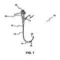
- FIG. 1 is a perspective view of a prior art endoscope system.
- FIG. 2 is cross-sectional view of a distal portion of an endoscope according to an embodiment of the present invention.
- FIG. 3 is a perspective view of components of an endoscope positioning mechanism according to an embodiment of the present invention.
- FIG. 4 is a cross-sectional view of an endoscope taken along line 4-4 in FIG. 2 .
- FIG. 5 is a cross-sectional view of an endoscope taken along line 5-5 in FIG. 2 .
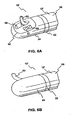
- FIG. 6A is a perspective view of a distal part of an endoscope according to an embodiment of the present invention.
- FIG. 6B is a perspective view of a distal part of an endoscope according to an embodiment of the present invention.
- FIG. 7 illustrates a cross-sectional view of a joint in an endoscope positioning mechanism, according to another example.
- FIG. 8A depicts a partially exploded perspective view of a distal and proximal portion of an endoscope positioning mechanism, according to another example.
- FIG. 8B depicts a side view of an assembled endoscope from FIG. 8A illustrated prior to rotation of a rotating portion.
- FIG. 8C depicts a side view of an assembled endoscope from FIG. 8A illustrated during rotation of a rotating portion.
- FIG. 9 illustrates the positioning of an endoscope and treatment device within a patient's body portion.
- the invention relates to a medical device for positioning a treatment device and/or viewing a patient's internal body portion.
- the treatment device can be advanced through a working channel of an endoscope, including an endoscope specifically designed and/or sized for use with the treatment device, and into a tissue tract.
- treatment device or “treatment instrument” includes, for example, any working medical device advanced through a working channel of an endoscope and for use during an endoscopic procedure.
- Exemplary treatment instruments include, but are not limited to, guide wires, cutting or grasping forceps, biopsy devices, snare loops, injection needles, cutting blades, scissors, retractable baskets, retrieval devices, ablation and/or electrophysiology catheters, stent placement devices, surgical stapling devices, and balloon catheters.
- FIG. 1 illustrates a known endoscope system.
- distal refers to the end further from the device operator during use and "proximal” refers to the end closer to the device operator during use.
- FIG. 1 depicts an endoscope 10 including a flexible outer tube 12 extending between a distal end 14 and a proximal end 16 of the device.
- Endoscope 10 includes a treatment device insertion port 11 for receiving a treatment device 20 into a working channel of the endoscope 10.
- the distal end 14 of the endoscope system 10 includes a side facing operation window 18 that can include visualization and lighting components for viewing during a treatment procedure.
- a working channel (not shown) extends within the endoscope 10 and terminates at the operation window 18, thereby allowing the treatment instrument 20 to be extended from the distal end of the endoscope 10.
- the extension of the treatment instrument 20 at a desired treatment site can be then be viewed through the visualization components, which transmit images to the proximal end of the endoscope 10, as in known in the art. While FIG. 1 illustrates a side facing operation window 18, both front/forward facing and oblique/intermediate angled windows are known.
- FIG. 2 illustrates a cross-sectional view of a distal portion of an endoscope system 10' according to an exemplary embodiment.
- Endoscope system 10' includes an outer flexible tube 12', which extends distally from a handle (not shown) at the proximal end of the system.
- a joint 22 connects a rotating portion 24 of endoscope 10' to a remaining proximal portion 26 of the endoscope 10'.
- Joint 22 can be formed of an anti-friction bearing mechanism, such as, a roller bearing, a ball bearing mechanism, or a magnetic bearing.
- joint 22 may be a portion of tube 12' that is much more flexible than the portions of tube 12' that comprise portions 24, 26 of endoscope 10'.
- That flexible joint 22 permits a certain degree of rotation about a longitudinal axis of endoscope 10' and tube 12' at joint 22.
- rotation may be up to 270 degrees.
- joint 22 may be integrally manufactured with the other portions 24, 26 of endoscope 10' or joint 22 may be a discrete component that attaches portion 24 to portion 26.
- joint 22 could be comprised of an arrangement of two ring gears, one inside the other at joint 22 such that external teeth of an internal ring rear engage and transmit rotational force to internal teeth of a complementary external ring gear.
- rotating portion 24 is configured for rotation relative to proximal portion 26. That rotation is about a longitudinal axis of endoscope 10' and tube 12'.
- Joint 22 should be configured in a fluid-tight arrangement in order to prevent contamination and corrosion of the internal components of endoscope '10' due to contact within a patient's internal body fluids.
- a number of pull wires wrapped around a spool could rotate portion 24.
- Additional examples include, but are not limited to electronic actuators, such as a stepper motor, cam drivers, a worm gear arrangement, or a pull wire system comprising a pulley type arrangement.
- the endoscope 10' may include known positioning structure for navigating the endoscope 10' and a treatment instrument through the tortuous pathways of a patient's internal body portion.
- endoscope 10' may include pull wires for effectuating deflection during positioning and an elevator device for altering the angle at which a treatment instrument exits the endoscope 10'.
- the proximal portion 26 of endoscope 10' includes a central lumen 28 within the endoscope 10', which extends from the proximal end of the endoscope 10' and terminates at the distal end of proximal portion 26.
- Rotating portion 24 includes a lumen 30 that connects with central lumen 28 of proximal portion 26.
- Lumen 30 extends distally within rotating portion 24 and curves to extend laterally, terminating at a side facing operation window 32.
- operation window 32 is disposed along an exterior side surface of rotating portion 24. While FIG. 2 illustrates a side facing operation window 32, embodiments of the invention include both oblique/intermediate angled windows and a front/forward facing embodiment where lumen 30 extends distally to a position offset from the center of the endoscope.
- Lumens 28 and 30 of endoscope 10' are configured to receive visualization components, such as, for example, known endoscopic imaging elements comprising illumination devices and fiber optic viewing elements for the transfer of images to the proximal end of the endoscope as known in the art.
- a portion of lumens 28 and 30 may further comprise an endoscopic working channel for receiving and guiding a treatment instrument therethrough.
- joint 22 will include a hole 29 that connects lumens 28 and 30 during positioning of endoscope 10' and rotation of rotating portion 24 relative to proximal portion 26.
- a portion of operation window 32 can include a working channel exit port (see item 56 of FIGS. 6A-6B ) through which a treatment instrument is extended during a medical procedure.
- the treatment instrument delivered through this endoscope could be designed for increased flexibility of rotation at a distal end portion, thereby accommodating rotation of the rotating portion 24 of the endoscope 10'.
- a distal end portion of a treatment instrument could be provided with a rotatable or twistable component.
- proximal portion 26 includes a rotation component lumen 34 that extends distally to communicate with a rotation component cavity 36 within rotating portion 24.
- joint 22 includes a hole 29 connecting lumens 28 and 30, joint 22 also includes an aperture (not shown) connecting lumen 34 and cavity 36.
- Rotation component cavity 36 extends distally within rotating portion 24 leading to a force transfer region 38.
- a torque transfer element such as, for example, flexible drive shaft 40 is provided within the rotation component lumen 34 and extends distally through cavity 36 terminating at force transfer region 38.
- the proximal end of drive shaft 40 is connected to any known type of positioning control mechanism at a handle at the proximal end of endoscope 10' to effectuate rotation of flexible drive shaft 40.
- FIG. 3 illustrates one example of components for a torque transferring mechanism for endoscope 10'.
- the force transferring mechanism comprises a spur gear arrangement.
- the arrangement includes a gear pair comprising a larger gear 42 having internal teeth 44 and a pinion 46 with external teeth 48 connected to the distal end of the flexible drive shaft 40.
- External teeth 48 of pinion 46 mesh with internal teeth 44 of gear 42 such that when torque is applied to flexible drive shaft 40, rotary motion is transferred to outer larger gear 42.
- the external surface of gear 42 may form part of the external surface of the outer flexible tube 12' of endoscope 10'.
- gear 42 may be embedded within tube 12'.
- gear 42 is integrated with rotating portion 24, torque applied to the flexible drive shaft 40 within rotation component lumen 34 effectuates rotation of rotating portion 24 relative to proximal portion 26. Therefore, rotation of flexible drive shaft 40 effectuates rotation of rotating portion 24 about the longitudinal axis of flexible tube 12'.
- lumens 28 and 30 of endoscope 10' are configured to receive visualization components and at least one treatment instrument therein, complete rotation of rotating portion 24 could hinder the proper operation of those components.
- multiple rotations of rotating portion 24 about the longitudinal axis of tube 12' could damage the internal components due to tangling of the elongated components and extreme amounts of torsion within the components housed in lumens 28 and 30.
- permitting rotation in an amount less than a full 360 degrees is preferred.
- certain structure could be provided within the internal components of endoscope 10' in order to prevent rotation beyond a particular predetermined angular threshold.
- FIGS. 4 and 5 illustrate one example of an arrangement of internal endoscope components for preventing excessive rotation of rotating portion 24.
- FIG. 4 represents a cross-sectional view of endoscope 10' taken along line 4-4 in FIG. 2 .
- the cross-section of rotating portion 24 depicts a portion of lumpen 30 coaxially disposed therein.
- Rotation component cavity 36 is provided to form an arc shape within rotating portion 24.
- FIG. 4 also depicts the cross-section of flexible drive shaft 40, which extends through the cavity 36.
- FIG. 5 by contrast, depicts a cross-sectional view of endoscope 10' taken along line 5-5 in FIG. 2 .
- FIG. 5 illustrates a portion of central lumen 28, coaxially disposed within proximal portion 26 of the endoscope 10'.
- FIG. 5 further depicts rotation component lumen 34, which houses flexible drive shaft 40 therein.
- Arc shaped rotation component cavity 36 is formed to exhibit a constant radius of curvature. Therefore, every point along the arc shaped rotation component cavity 36 is equidistant from the center of tube 12' of endoscope 10'. Accordingly, when the flexible drive shaft 40 is rotated, first and second ends 52 and 54 of arc shaped rotation component cavity 36 provide a boundary limiting the extent to which rotating portion 24 is permitted to rotate relative to proximal portion 26. In order to prevent an excessive torque transmission or excessive torsion stored along the flexible drive shaft 10', markers, or any other type of indicia, can be provided at the positioning control mechanism to depict the allowable limits of rotation. FIG. 4 shows an exemplary angular rotation of 180 degrees. Other predetermined angular rotations permitted by cavity 36 are within the scope of the invention.
- FIG. 6A depicts rotating portion 24 including side facing operation window 32 and a working channel exit port 56 through which a treatment instrument 60 is extended.
- FIG. 6A also illustrates an illumination window 57 and a visualization window 58 for viewing an internal treatment site during a medical procedure as used in known endoscope devices.
- FIG. 6B through actuation of flexible drive shaft 40, rotating portion 24 is rotated through a particular angle about the longitudinal axis of flexible outer tube 12'. Through this rotation, the angular orientation of exit port 56 can be precisely controlled. Accordingly, in the rotated view of FIG. 6B , neither operation window 32 nor exit port 56 are seen.
- This manipulation of rotating portion 24 and exit port 56 is advantageous in that precise angular rotation of exit port 56 is achieved without the unnecessary tissue trauma that may result from repeated manipulation and rotation of an entire endoscope within a patient's body portion.
- the arrangements of joint 22 facilitates the free rotation of portion 24 relative to proximal portion 26. Accordingly, inefficient torque transfer and buildup of torsion along the endoscope 10' is avoided.
- improper transfer of torque from the proximal end to the distal end can lead to an unwinding, or whipping, of the distal end during placement of the endoscope. Such problems are avoided by the rotation afforded by the present system.
- FIG. 7 depicts a cross-sectional view of a joint 22' including a planetary gear arrangement 90.
- Joint 22' is configured for use in any endoscope arrangement including a rotating portion 24 and a proximal portion 26, where rotation of a rotating portion 24 relative to a proximal portion 26 is desired (as depicted in FIGS. 6A-6B , for example).
- an external surface 100 of joint 22' can comprise the external exposed surface of a portion of the underlying endoscope. More, particularly, the external surface 100 can be integral with, or otherwise united with, a rotating portion 24, such that rotation of external surface 100 relative to the proximal portion 26, results in rotation of rotating portion 24 relative to proximal portion 26.
- a central portion of the planetary gear arrangement 90 includes a central aperture 29' connecting lumens 28 and 30, as described above, during positioning of an endoscope and rotation of rotating portion 24 relative to proximal portion 26, for example. Accordingly, visualization components and at least one treatment instrument extend through aperture 29' when used in a system comprised of joint 22'.
- the planetary gear system includes a central cog-wheel, called the sun gear 92 having external sun gear teeth 93.
- the central aperture 29' extends through sun gear 92.
- the sun gear 92 is surrounded by one or more planet gears 94.
- Each of the planet gears 94 include planet gear teeth 95 that engage sun gear teeth 93.
- the planet gears 94 also engage internal teeth 96 of an external ring gear 97, also commonly referred to as an annulus.
- a carrier 98 is coupled with the planet gears 93.
- two cylindrical prongs 99 of carrier 98 are coupled with each of the illustrated planet gears 93.
- the central aperture 29' extends through carrier 98 just as it extends through sun gear 92.
- rotation is transmitted from one element to another in the gear network by grounding, also called locking, one element (i.e. either the sun gear 93, the ring gear 97, or the carrier 98) to a stationary component of structure.
- grounding also called locking
- one element i.e. either the sun gear 93, the ring gear 97, or the carrier 98
- the locked component of planetary gear system 90 will be connected, or otherwise held stationary relative to, the proximal portion 26 of the underlying endoscope.
- carrier 98 is grounded by virtue of connection to a proximal portion 26 of the underlying endoscope. As such, carrier 98 will not rotate relative to the proximal portion 26. In such an arrangement, rotation of rotating portion 24 can be effectuated through rotation of sun gear 92 relative to carrier 98. For example, due to the engagement of gear teeth 93, 95, and 96, rotation of sun gear 92 in a first direction results in concurrent rotation of the planet gears 94 and, in turn, ring gear 97, in a second rotational direction opposite the first direction.
- Rotation of sun gear 93 relative to carrier 98 can be effectuated through any known torque transfer element.
- a hollow, flexible drive shaft (not shown) can be provided within the proximal portion 26 of the underlying endoscope. The proximal end of the drive shaft is then connected to any known type of positioning control mechanism at a handle at the proximal end of the underlying endoscope. Accordingly, in such an arrangement a user can control rotation of rotating portion 24 through actuation of a positioning mechanism that in turn results in rotation of sun gear 92.
- sun gear 92 is grounded by virtue of connection to a proximal portion 26 of the underlying endoscope. As such, sun gear 92 will not rotate relative to the proximal portion 26. in such an arrangement, rotation of rotating portion 24 can be effectuated through rotation of carrier 98 relative to sun gear 92. For example, due to the engagement of gear teeth 93, 95, and 96, rotation of carrier 98 in a first direction results in rotation of planet gears 94 about the locked sun gear 92. The movement and rotation of planet gears 94 also results in rotation of ring gear 97 in the same direction as carrier 98.
- rotation of carrier 98 can be effectuated through any known torque transfer element.
- a hollow, flexible drive shaft (not shown) can be provided within the proximal portion 26 of the underlying endoscope. The proximal end of the drive shaft is then connected to any known type of positioning control mechanism at a handle at the proximal end of the underlying endoscope. Accordingly, in such an arrangement, a user can control rotation of rotating portion 24 through actuation of a positioning mechanism that in turn results in rotation of carrier 98.
- FIGS. 8A-8C depict another example of a mechanism for rotating a rotating endoscope portion relative to a proximal portion.
- a complementary pin and helical groove arrangement can be used to permit relative rotation of two endoscope portions.
- FIG. 8A depicts a partially exploded isometric view of two endoscope portions 24' and 26' respectively.
- Item 24' depicts a distal rotating portion of an underlying endoscope.
- rotating portion 24' may include an operation window 32' including a working channel exit port 56'.
- a proximal portion of rotating portion 24' includes a reduced diameter portion 102.
- the reduced diameter portion 102 may also include an engagement pin 104 outwardly radially extending therefrom.
- Item 26' depicts a flexible proximal endoscope portion 26'.
- Proximal portion 26' can be hollow and configured for rotationally receiving the reduced diameter portion 102 within a distal portion thereof.
- an internal surface of proximal portion 26' may include an internal helical groove 106 extending therein.
- the rotating portion 24' is received within the proximal portion in a fluid tight manner, but one that still allows rotation of rotating portion 24' relative to proximal portion 26'.
- a fluid tight arrangement can be provided through the use of sealing projections (not shown) along reduced diameter portion 102, or within the hollow proximal portion 26'. Additionally, or alternatively, a fluid tight arrangement can be provided through the use of a gasket or o-ring element.
- FIG. 8B is a side view of an endoscope arrangement depicting rotating portion 24' united with proximal portion 26'.
- the internal helical groove 106 of proximal portion 26' is depicted in FIG. 8B .
- the helical groove 106 extends proximally within proximal portion 26, transitioning into a linear groove 108.
- engagement pin 104 of rotating portion 24' is seated within and operatively engaged within the linear groove 108 of the proximal portion 26'.
- the very proximal end of the groove 108 terminates in a reduced size engagement section 109.
- the engagement pin 104 Prior to rotation of rotating portion 24', the engagement pin 104 is releasably seated at the proximal end of linear groove 108 within the terminal engagement section 109.
- the relation between the engagement pin 104 and engagement section 109 may be such that the pin 104 is selectively or otherwise releasable from, and in certain arrangements re-engagable with, the engagement section 109.
- the engagement between pin 104 and engagement section 109 may be achieved, for example, by a male/female connection in which a portion of pin 104 is inserted and received within the engagement section 109, which is of a reduced size configured to releasably receive the pin 104 by virtue of an interference fit.
- the engagement may be realized, for example, by a ball and socket type connection, a friction fit engagement, a screw-like configuration or any other releasable engagement mechanisms known to one having ordinary skill in the art.
- Rotation of rotating portion 24' can be effectuated through controlled movement of engagement pin 104 within both linear groove 108 and helical groove 106. To initiate rotation, the rotating portion 24' must be moved relative to the proximal portion 26' with an initial forward displacement force of a magnitude great enough to overcome the force with which engagement section 109 holds pin 104. Rotating portion 24' can be displaced relative to the proximal portion 26' with any known force transfer element.
- Suitable force transfer elements include, but are not limited to, push wires, stylets, cam drivers, stepper motors, a pull wire arrangement where a pulley type system changes a proximal pulling force into a distally directed one, and/or piezoelectric transducers provided within the proximal portion 26' of the underlying endoscope.
- an operator can first linearly displace rotating portion 24' relative to proximal portion 26' such that engagement pin 104 moves along linear groove 108 and into the helical groove 106.
- a dovetail protrusion and complementary groove could also be used.
- the helical groove 106 and pin 104 could be reversed such that a pin 104, or other protrusion, is formed on an interior of proximal portion 26' and with a helical groove formed on the reduced diameter portion 102 of rotating portion 24'.
- groove 106 and engagement pin 104 can be reversed.
- helical groove 106 could be provided along an exterior surface of reduced diameter portion 102 of rotating portion 24' and engagement pin 104 could be provided along an internal surface of proximal portion 26'.
- the rotating portion 24' and proximal portion 26' could be connected and rotatable relative to each other through any type of mating thread arrangement.
- rotation of one endoscope portion relative to another can be achieved in a range even greater that 360 degrees, for example.
- the only limiting factor in such configurations will be the extent to which internal visualization components and treatment instruments can withstand, or be enabled for, concurrent rotation within internal endoscope lumens in order to resist winding and kinking due to excessive rotation.
- the rotation of one endoscope portion relative to another should protected from contamination by structure providing a fluid tight arrangement.
- the rotation of one portion relative to another can be facilitated by virtue of any lubrication element and or friction reducing structure.
- a particular lubricious coating can be provided along the surfaces where repeated engagement or moving parts takes place.
- FIG. 9 illustrates the positioning of an endoscope 10' and treatment device 60 within a patient's body portion.
- FIG. 9 depicts the extension of a treatment instrument 60 within a particular bile duct 80 during an ERCP procedure.
- the endoscope 10' for example, is inserted and extended through a patient's stomach 82 such that the distal end and exit port 56 (not shown) of endoscope 10' are positioned is close relation to a particular bile duct 80 leading to, for example, gall bladder 84.
- treatment instrument 60 is extended beyond an internal working channel of endoscope 10'.
- the angular direction at which treatment instrument 60 extends from endoscope 10' can then be altered, for example, by controlled rotation of rotating portion 24 relative to proximal portion 26 of endoscope 10'. Accordingly, rotation of portion 24 relative to the rest of endoscope 10' repositions the orientation of treatment instrument 60 without requiring rotation of the entire underlying endoscope 10'.
- rotation of one endoscope portion relative to another can be up to 360 degrees in some embodiment (such as, for example, the embodiments of FIGS. 7 and 8A-8C ). In other embodiments, excessive rotation is unnecessary. For example, in some embodiments rotation is only necessary, and the underlying structure can therefore be limited to, within a range of about 0-10 degrees, 0-20 degrees, or 0-30 degrees.
- the exit port 56 along the distal portion of endoscope 10' can be repeatedly repositioned at different longitudinal locations within a patient's body.
- Treatment instrument 60 can then be deployed at each different location and precisely positioned to access a desired treatment site at that location.
- Angular adjustment of the orientation of treatment instrument 60 as it extends from endoscope 10' at consecutive treatment locations can reduce internal tissue trauma resulting from repeated rotation of an entire endoscope during a treatment procedure.
- precise manipulation of a treatment device 60 can result in shortened treatment procedures by reducing the amount of time necessary to effectuate proper position of the treatment device 60.
Landscapes
- Health & Medical Sciences (AREA)
- Life Sciences & Earth Sciences (AREA)
- Surgery (AREA)
- Engineering & Computer Science (AREA)
- Heart & Thoracic Surgery (AREA)
- Biophysics (AREA)
- Veterinary Medicine (AREA)
- Public Health (AREA)
- General Health & Medical Sciences (AREA)
- Animal Behavior & Ethology (AREA)
- Biomedical Technology (AREA)
- Medical Informatics (AREA)
- Physics & Mathematics (AREA)
- Molecular Biology (AREA)
- Radiology & Medical Imaging (AREA)
- Pathology (AREA)
- Optics & Photonics (AREA)
- Nuclear Medicine, Radiotherapy & Molecular Imaging (AREA)
- Pulmonology (AREA)
- Anesthesiology (AREA)
- Hematology (AREA)
- Mechanical Engineering (AREA)
- Gastroenterology & Hepatology (AREA)
- Endoscopes (AREA)
Claims (23)
- Medizinprodukt, umfassend:eine längliche flexible Röhre (12'), die eine Längsachse bestimmt und einen proximalen Abschnitt (26) und einen distalen Abschnitt (24), der mit dem proximalen Abschnitt (26) über eine Verbindung (22) verbunden ist, umfasst, wobei die flexible Röhre (12') ein Lumen (28, 30) bestimmt, das sich durch den proximalen Abschnitt (26) und den distalen Abschnitt (24) erstreckt und zu einer Öffnung (32) an einem distalen Ende der flexiblen Röhre (12') führt; und wobei sich der distale Abschnitt (24) relativ zum proximalen Abschnitt (26) dreht, dadurch gekennzeichnet, dass der distale Abschnitt (24) einen Hohlraum (36) bestimmt, wobei Anschläge (52, 54) den Hohlraum (36) begrenzen, um die Drehung des distalen Abschnitts (24) über einen bestimmten Winkel hinaus zu verhindern, wobei ein zweites Lumen (34) in dem proximalen Abschnitt (26) bestimmt ist und ein Drehmomentübertragungselement (40) darin beherbergt, wobei sich der Hohlraum (36) distal innerhalb des distalen Abschnitts (24) erstreckt und einen distalen Abschnitt des Drehmomentübertragungselements (40) aufnimmt, der sich distal über das zweite Lumen (34) hinaus erstreckt und wobei die Drehung des Drehmomentübertragungselements (40) eine Drehbewegung auf den distalen Abschnitt (24) überträgt, und wobei der Hohlraum (36) bemessen ist, die Drehung des distalen Abschnitts (24) mit einem Wert von weniger als 360 Grad relativ zum proximalen Abschnitt (26) zu gestatten.
- Medizinprodukt nach Anspruch 1, wobei die Öffnung (32) entlang einer Außenseitenfläche des distalen Abschnitts (24) angeordnet ist und sich das Lumen (28, 30) distal innerhalb des distalen Abschnitts (24) erstreckt und sich krümmt, um an der Öffnung (32) zu enden.
- Medizinprodukt nach Anspruch 1, wobei das Lumen (28, 30) ausgestaltet ist, ein Behandlungsinstrument darin aufzunehmen, das sich während eines medizinischen Eingriffs durch die Öffnung (32) erstrecken kann.
- Medizinprodukt nach Anspruch 3, wobei das Lumen (28, 30) ausgestaltet ist, ein Behandlungsinstrument darin aufzunehmen, das sich durch die Öffnung (32) erstrecken kann, wenn der distale Abschnitt (24) relativ zum proximalen Abschnitt (26) gedreht wird.
- Medizinprodukt nach Anspruch 1, wobei die Verbindung (22) ein Lager umfasst.
- Medizinprodukt nach Anspruch 1, wobei die Verbindung (22) flexibler ist als sowohl der distale als auch proximale Abschnitt (24, 26) der flexiblen Röhre (12').
- Medizinprodukt nach Anspruch 1, wobei das Drehmomentübertragungselement (40) eine Welle umfasst, die sich distal zu einer Zahnradanordnung im distalen Abschnitt (24) erstreckt, sodass, wenn auf die Welle ein Drehmoment übertragen wird, eine Drehbewegung übertragen wird, um den distalen Abschnitt (24) relativ zum proximalen Abschnitt (26) zu drehen.
- Medizinprodukt nach Anspruch 1, wobei der Hohlraum (36) eine Bogenform aufweist, die einen konstanten Krümmungsradius aufweist, sodass während der Drehung des distalen Abschnitts (24) das Drehmomentübertragungselement (40) einen konstanten Abstand zur Mitte der länglichen flexiblen Röhre (12') beibehält.
- Medizinprodukt nach Anspruch 1, wobei das Lumen (28) des proximalen Abschnitts (26) mittig im proximalen Abschnitt (26) angeordnet ist.
- Medizinprodukt nach Anspruch 9, wobei ein distales Ende des Lumens (28) im proximalen Abschnitt (26) mit einem proximalen Abschnitt des Lumens (30) im distalen Abschnitt (24) in Verbindung steht.
- Medizinprodukt nach Anspruch 9, wobei das Lumen (28) im proximalen Abschnitt (26) über eine Öffnung in der Verbindung (22) mit dem Lumen (30) im distalen Abschnitt (24) in Verbindung steht.
- Medizinprodukt nach Anspruch 1, wobei ein proximaler Abschnitt des Lumens (30) des distalen Abschnitts (24) mittig im distalen Abschnitt (24) angeordnet ist.
- Medizinprodukt nach Anspruch 1, wobei in dem Lumen (28, 30) des proximalen Abschnitts (26) und des distalen Abschnitts (24) 5ichtbarmachungs- und Beleuchtungskomponenten vorgesehen sind.
- Medizinprodukt nach Anspruch 1, wobei die Verbindung (22) ein Planetengetriebesystem umfasst.
- Medizinprodukt nach Anspruch 14, wobei das Planetengetriebesystem ein Sonnenrad, mindestens ein Planetenrad, ein Hohlrad und einen Träger aufweist.
- Medizinprodukt nach Anspruch 15, wobei eine Außenfläche des Hohlrads eine Außenfläche der Verbindung (22) entlang einer Außenfläche des Medizinprodukts bildet.
- Medizinprodukt nach Anspruch 16, wobei die Verbindung (22) in den distalen Abschnitt (24) integriert ist.
- Medizinprodukt nach Anspruch 14, wobei sich das Lumen (28, 30) der flexiblen Röhre (12') durch eine Öffnung erstreckt, die durch das Planetengetriebesystem hindurch vorgesehen ist.
- Medizinprodukt nach Anspruch 15, wobei das Sonnenrad durch die Verbindung zum proximalen Abschnitt (26) derart festgestellt ist, dass die Drehung des Trägers zur Drehung des Hohlrads und des distalen Abschnitts (24) führt.
- Medizinprodukt nach Anspruch 1, wobei die Drehung des distalen Abschnitts (24) relativ zum proximalen Abschnitt (26) auf einen Bereich von ungefähr 0 bis 30 Grad eingeschränkt ist.
- Medizinprodukt nach Anspruch 1, wobei die Drehung des distalen Abschnitts (24) relativ zum proximalen Abschnitt (26) auf einen Bereich von ungefähr 0 bis 20 Grad eingeschränkt ist.
- Medizinprodukt nach Anspruch 1, wobei die Verbindung (22) vom proximalen Abschnitt (26) und distalen Abschnitt (24) getrennt ist.
- Medizinprodukt nach Anspruch 22, wobei ein proximales Ende des distalen Abschnitts (24) direkt mit einem Ende der Verbindung (22) verbunden ist und ein distales Ende des proximalen Abschnitts (26) direkt mit dem anderen Ende der Verbindung (22) verbunden ist.
Applications Claiming Priority (2)
| Application Number | Priority Date | Filing Date | Title |
|---|---|---|---|
| US11/430,067 US7753843B2 (en) | 2006-05-09 | 2006-05-09 | Medical device positioning system |
| PCT/US2007/061450 WO2007130720A1 (en) | 2006-05-09 | 2007-02-01 | Medical device positioning system |
Publications (2)
| Publication Number | Publication Date |
|---|---|
| EP2020900A1 EP2020900A1 (de) | 2009-02-11 |
| EP2020900B1 true EP2020900B1 (de) | 2012-06-06 |
Family
ID=38068842
Family Applications (1)
| Application Number | Title | Priority Date | Filing Date |
|---|---|---|---|
| EP07717508A Active EP2020900B1 (de) | 2006-05-09 | 2007-02-01 | Positionierungssystem für ein medizinprodukt |
Country Status (3)
| Country | Link |
|---|---|
| US (7) | US7753843B2 (de) |
| EP (1) | EP2020900B1 (de) |
| WO (1) | WO2007130720A1 (de) |
Cited By (2)
| Publication number | Priority date | Publication date | Assignee | Title |
|---|---|---|---|---|
| WO2022258419A1 (de) * | 2021-06-07 | 2022-12-15 | B. Braun New Ventures GmbH | Endoskopischer navigationszeiger |
| DE102017100866B4 (de) | 2017-01-18 | 2024-05-08 | Hoya Corporation | Endoskop mit einem Endoskopkopf mit einem Arbeitskanal zum Führen von Mikrowerkzeugen |
Families Citing this family (64)
| Publication number | Priority date | Publication date | Assignee | Title |
|---|---|---|---|---|
| US7951071B2 (en) * | 1999-06-02 | 2011-05-31 | Tyco Healthcare Group Lp | Moisture-detecting shaft for use with an electro-mechanical surgical device |
| US7918783B2 (en) * | 2006-03-22 | 2011-04-05 | Boston Scientific Scimed, Inc. | Endoscope working channel with multiple functionality |
| JP5118867B2 (ja) * | 2007-03-16 | 2013-01-16 | オリンパス株式会社 | 内視鏡観察装置および内視鏡の作動方法 |
| US8357145B2 (en) * | 2007-11-12 | 2013-01-22 | Boston Scientific Neuromodulation Corporation | Implanting medical devices |
| FR2924919B1 (fr) * | 2007-12-12 | 2010-01-22 | Salah Hassanin | Ensemble de robot chirurgical et industrielle mains libres pour endoscopie |
| US8425573B2 (en) * | 2008-10-24 | 2013-04-23 | The Cleveland Clinic Foundation | Method and system for attaching a plate to a bone |
| US20100274081A1 (en) * | 2009-04-22 | 2010-10-28 | Tyco Healthcare Group Lp | Visual veress needle assembly |
| US10149601B2 (en) | 2009-12-15 | 2018-12-11 | Lumendi Ltd. | Method and apparatus for manipulating the side wall of a body lumen or body cavity so as to provide increased visualization of the same and/or increased access to the same, and/or for stabilizing instruments relative to the same |
| US10485401B2 (en) | 2009-12-15 | 2019-11-26 | Lumendi Ltd. | Method and apparatus for manipulating the side wall of a body lumen or body cavity so as to provide increased visualization of the same and/or increased access to the same, and/or for stabilizing instruments relative to the same |
| US12121209B2 (en) | 2014-02-11 | 2024-10-22 | Cornell University | Method and apparatus for providing increased visualization and manipulation of a body side wall |
| US8979884B2 (en) | 2009-12-15 | 2015-03-17 | Cornell University | Method and apparatus for stabilizing, straightening, expanding and/or flattening the side wall of a body lumen and/or body cavity so as to provide increased visualization of the same and/or increased access to the same, and/or for stabilizing instruments relative to the same |
| US9986893B2 (en) | 2009-12-15 | 2018-06-05 | Cornell University | Method and apparatus for manipulating the side wall of a body lumen or body cavity so as to provide increased visualization of the same and/or increased access to the same, and/or for stabilizing instruments relative to the same |
| US11986150B2 (en) | 2009-12-15 | 2024-05-21 | Lumendi Ltd. | Method and apparatus for manipulating the side wall of a body lumen or body cavity so as to provide increased visualization of the same and/or increased access to the same, and/or for stabilizing instruments relative to the same |
| US11877722B2 (en) | 2009-12-15 | 2024-01-23 | Cornell University | Method and apparatus for manipulating the side wall of a body lumen or body cavity |
| JP5389721B2 (ja) * | 2010-03-31 | 2014-01-15 | 富士フイルム株式会社 | 内視鏡用フード |
| US20120116233A1 (en) * | 2010-11-04 | 2012-05-10 | Robert Weber Mah | Sensor system |
| US8617087B2 (en) * | 2010-12-03 | 2013-12-31 | Biosense Webster, Inc. | Control handle with rotational cam mechanism for contraction/deflection of medical device |
| US8792962B2 (en) | 2010-12-30 | 2014-07-29 | Biosense Webster, Inc. | Catheter with single axial sensors |
| CN102697476A (zh) * | 2012-01-18 | 2012-10-03 | 广州宝胆医疗器械科技有限公司 | 多普勒激光oct胆囊镜系统 |
| CN102688112B (zh) * | 2012-06-29 | 2015-03-04 | 东莞市博迪思迈医疗器械有限公司 | 支架输送装置 |
| DE102012212094B4 (de) * | 2012-07-11 | 2025-09-11 | Richard Wolf Gmbh | Endoskopisches Instrument |
| CN104619232B (zh) * | 2012-09-12 | 2016-10-05 | 奥林巴斯株式会社 | 驱动力传递单元、插入设备、旋转单元、插入主体组件和插入装置 |
| DE102012024413B4 (de) * | 2012-12-14 | 2014-07-10 | Krohne Messtechnik Gmbh | Positioniervorrichtung und Messgerät |
| CN103690282B (zh) * | 2013-12-31 | 2016-02-17 | 先健科技(深圳)有限公司 | 管腔支架输送系统 |
| WO2016021233A1 (ja) * | 2014-08-06 | 2016-02-11 | オリンパス株式会社 | 内視鏡 |
| US9585547B2 (en) * | 2014-11-24 | 2017-03-07 | Gyrus Acmi, Inc. | Adjustable endoscope sheath |
| US10603195B1 (en) | 2015-05-20 | 2020-03-31 | Paul Sherburne | Radial expansion and contraction features of medical devices |
| US10765306B2 (en) | 2015-07-29 | 2020-09-08 | Tarek Ahmed Nabil Abou El Kheir | Advanced 3-dimensional endoscopic system with real dynamic convergence |
| US10849521B2 (en) | 2015-12-23 | 2020-12-01 | Biosense Webster (Israel) Ltd. | Multi-layered catheter shaft construction with embedded single axial sensors, and related methods |
| CN110325098A (zh) | 2016-11-28 | 2019-10-11 | 适内有限责任公司 | 具有可分离一次性轴的内窥镜 |
| CN115736792A (zh) * | 2017-02-01 | 2023-03-07 | 波士顿科学国际有限公司 | 具有多个观察方向的内窥镜 |
| JP7250688B2 (ja) | 2017-03-03 | 2023-04-03 | ボストン サイエンティフィック サイムド,インコーポレイテッド | 装置先端部 |
| CN111655112B (zh) * | 2018-01-30 | 2024-10-11 | 波士顿科学医学有限公司 | 医疗系统、设备和相关方法 |
| DE102018208555A1 (de) | 2018-05-30 | 2019-12-05 | Kardion Gmbh | Vorrichtung zum Verankern eines Herzunterstützungssystems in einem Blutgefäß, Verfahren zum Betreiben und Herstellverfahren zum Herstellen einer Vorrichtung und Herzunterstützungssystem |
| DE102018208564A1 (de) | 2018-05-30 | 2019-12-05 | Kardion Gmbh | Steuerbare Einführungshülse |
| DE102018208537A1 (de) | 2018-05-30 | 2019-12-05 | Kardion Gmbh | Vorrichtung zum Anbinden eines Herzunterstützungssystems an eine Einführeinrichtung und Verfahren zum Herstellen einer Vorrichtung zum Anbinden eines Herzunterstützungssystems an eine Einführeinrichtung |
| DE102018211297A1 (de) | 2018-07-09 | 2020-01-09 | Kardion Gmbh | Herzunterstützungssystem und Verfahren zur Überwachung der Integrität einer Haltestruktur eines Herzunterstützungssystems |
| CN112672673B (zh) * | 2018-09-10 | 2024-05-14 | 富士胶片株式会社 | 内窥镜 |
| JP7251940B2 (ja) * | 2018-09-28 | 2023-04-04 | i-PRO株式会社 | 斜視内視鏡 |
| JP7053445B2 (ja) * | 2018-12-17 | 2022-04-12 | パナソニックi-PROセンシングソリューションズ株式会社 | 斜視内視鏡 |
| DE112019004890T5 (de) * | 2018-09-28 | 2021-06-10 | Panasonic I-Pro Sensing Solutions Co., Ltd. | Endoskop mit schräger Blickrichtung |
| EP3860477B1 (de) * | 2018-11-09 | 2024-03-27 | Meditrina, Inc. | Endoskop |
| AU2020206791B2 (en) * | 2019-01-11 | 2025-08-14 | Dragonfly Endoscopy Llc | Endoscopic device and methods of use thereof |
| CN110367909B (zh) * | 2019-08-23 | 2021-07-06 | 哈尔滨工业大学 | 一种新型的消化内镜送进装置 |
| EP3811842B1 (de) * | 2019-10-23 | 2026-01-21 | Medizinische Universität Wien | Endoskop |
| WO2021127518A1 (en) * | 2019-12-20 | 2021-06-24 | Murdeshwar Nikhil M | Endoscope with detachable handle module |
| CN113080833B (zh) * | 2019-12-23 | 2023-01-03 | 财团法人工业技术研究院 | 光纤扫描探头及内视镜 |
| USD1018844S1 (en) | 2020-01-09 | 2024-03-19 | Adaptivendo Llc | Endoscope handle |
| US11547286B2 (en) * | 2020-01-22 | 2023-01-10 | Brio13Inv. LLC | Stylet assembly |
| JP7830345B2 (ja) * | 2020-04-10 | 2026-03-16 | ボストン サイエンティフィック サイムド,インコーポレイテッド | 医療装置の遠位先端 |
| JP7524349B2 (ja) * | 2020-06-26 | 2024-07-29 | クック・メディカル・テクノロジーズ・リミテッド・ライアビリティ・カンパニー | 内視鏡屈曲セクション |
| EP4232132A4 (de) * | 2020-10-20 | 2024-09-11 | Boston Scientific Medical Device Limited | Lenkbares medizinisches gerät, handgriff für ein medizinisches gerät und verfahren zum betreiben eines medizinischen geräts |
| EP4243910A4 (de) | 2020-11-16 | 2024-12-25 | Lumendi Ltd. | Verfahren und vorrichtung zum wenden einer hohlen hülse und darauf folgender umkehr einer umgekehrten hohlen hülse |
| USD1051380S1 (en) | 2020-11-17 | 2024-11-12 | Adaptivendo Llc | Endoscope handle |
| JP2023550938A (ja) | 2020-11-20 | 2023-12-06 | カルディオン ゲーエムベーハー | ガイドワイヤ補助具付き機械的循環支持システム |
| CN112472153B (zh) * | 2020-12-14 | 2024-05-07 | 浙江工业大学 | 一种多角度调节的一次性活体取样钳 |
| USD1031035S1 (en) | 2021-04-29 | 2024-06-11 | Adaptivendo Llc | Endoscope handle |
| USD1070082S1 (en) | 2021-04-29 | 2025-04-08 | Adaptivendo Llc | Endoscope handle |
| US12396657B2 (en) | 2021-04-29 | 2025-08-26 | Biosense Webster (Israel) Ltd. | Non-linear single axis navigation sensor with strain relief |
| USD1066659S1 (en) | 2021-09-24 | 2025-03-11 | Adaptivendo Llc | Endoscope handle |
| US12527460B2 (en) * | 2021-10-27 | 2026-01-20 | Meditrina, Inc. | Endoscopic imaging and control system |
| US11950765B1 (en) * | 2023-04-29 | 2024-04-09 | Syncrobotix, Inc. | Highly maneuverable surgical catheter and bronchoscope |
| US12433693B2 (en) | 2023-04-29 | 2025-10-07 | Syncrobotix, Inc. | Rotary and linear actuated robotic catheter steering system |
| WO2025117011A1 (en) * | 2023-11-29 | 2025-06-05 | Syncrobotix Inc., A United States State Of Delaware Corporation | Rotary and linear actuated robotic catheter steering system |
Family Cites Families (45)
| Publication number | Priority date | Publication date | Assignee | Title |
|---|---|---|---|---|
| US3614891A (en) * | 1969-03-17 | 1971-10-26 | Prakla Seismos Gmbh | Well surveying instrument and method |
| US4176662A (en) * | 1977-06-17 | 1979-12-04 | The United States Of America As Represented By The Administrator Of The National Aeronautics And Space Administration | Apparatus for endoscopic examination |
| JPS57188231A (en) * | 1981-05-14 | 1982-11-19 | Olympus Optical Co | Treating tool guide apparatus of endoscope |
| US4699463A (en) * | 1985-11-01 | 1987-10-13 | Circon Corporation | Multidirectional viewing borescope |
| US4794911A (en) * | 1986-09-20 | 1989-01-03 | Olympus Optical Company Ltd. | Means to facilitate detachably mounting cap to distal end of endoscope |
| JPS63122419A (ja) * | 1986-11-11 | 1988-05-26 | 富士写真光機株式会社 | 内視鏡 |
| US4727859A (en) * | 1986-12-29 | 1988-03-01 | Welch Allyn, Inc. | Right angle detachable prism assembly for borescope |
| US4858001A (en) * | 1987-10-08 | 1989-08-15 | High-Tech Medical Instrumentation, Inc. | Modular endoscopic apparatus with image rotation |
| US4979496A (en) * | 1988-04-05 | 1990-12-25 | Fuji Photo Optical Co., Ltd. | Endoscope for bile duct and pancreatic duct |
| DE3921233A1 (de) * | 1989-06-28 | 1991-02-14 | Storz Karl Gmbh & Co | Endoskop mit einer am distalen ende angeordneten videoeinrichtung |
| US4941457A (en) * | 1989-08-17 | 1990-07-17 | Olympus Optical Co., Ltd. | Endoscope using an optical guide twisted on the tip side to have the visual field direction and curvature axis coincide with each other |
| US5312023A (en) * | 1991-10-18 | 1994-05-17 | United States Surgical Corporation | Self contained gas powered surgical apparatus |
| WO1994009694A1 (en) * | 1992-10-28 | 1994-05-11 | Arsenault, Dennis, J. | Electronic endoscope |
| JP3713286B2 (ja) | 1993-05-11 | 2005-11-09 | オリンパス株式会社 | 内視鏡カバー |
| US5624379A (en) * | 1995-10-13 | 1997-04-29 | G. I. Medical Technologies, Inc. | Endoscopic probe with discrete rotatable tip |
| IL151563A0 (en) * | 1995-10-13 | 2003-04-10 | Transvascular Inc | A longitudinal compression apparatus for compressing tissue |
| US5860913A (en) * | 1996-05-16 | 1999-01-19 | Olympus Optical Co., Ltd. | Endoscope whose distal cover can be freely detachably attached to main distal part thereof with high positioning precision |
| US6095970A (en) * | 1997-02-19 | 2000-08-01 | Asahi Kogaku Kogyo Kabushiki Kaisha | Endoscope |
| JPH11276422A (ja) * | 1998-03-31 | 1999-10-12 | Fuji Photo Optical Co Ltd | 超音波内視鏡 |
| JP3634671B2 (ja) * | 1999-06-21 | 2005-03-30 | ペンタックス株式会社 | 内視鏡 |
| ATE363235T1 (de) * | 1999-09-09 | 2007-06-15 | Tuebingen Scient Medical Gmbh | Chirurgisches instrument für minimal invasive eingriffe |
| US6354992B1 (en) * | 1999-11-08 | 2002-03-12 | Daniel T. Kato | Automated laparoscopic lens cleaner |
| JP4716594B2 (ja) * | 2000-04-17 | 2011-07-06 | オリンパス株式会社 | 内視鏡 |
| US6582357B2 (en) * | 2000-05-24 | 2003-06-24 | Pentax Corporation | Treating instrument erecting device for use in endoscope |
| US6537209B1 (en) * | 2000-09-14 | 2003-03-25 | Itconcepts, Inc. | Optical system of lateral observation endoscope |
| US6824509B2 (en) * | 2001-07-23 | 2004-11-30 | Olympus Corporation | Endoscope |
| US6632227B2 (en) * | 2001-08-24 | 2003-10-14 | Scimed Life Systems, Inc. | Endoscopic resection devices |
| US20030050639A1 (en) * | 2001-09-12 | 2003-03-13 | Harmonia Medical Technologies | Surgical instrument and method of using the same |
| JP3772107B2 (ja) * | 2001-10-12 | 2006-05-10 | オリンパス株式会社 | 内視鏡システム |
| US6663577B2 (en) * | 2001-12-07 | 2003-12-16 | Abbott Laboratories | Catheter deployment device |
| FR2838325A1 (fr) | 2002-04-12 | 2003-10-17 | Philippe Benoit | Endoscope |
| JP4488280B2 (ja) * | 2002-06-07 | 2010-06-23 | オリンパス株式会社 | 内視鏡用処置具および内視鏡装置 |
| US7066879B2 (en) * | 2003-07-15 | 2006-06-27 | The Trustees Of Columbia University In The City Of New York | Insertable device and system for minimal access procedure |
| US20050096502A1 (en) * | 2003-10-29 | 2005-05-05 | Khalili Theodore M. | Robotic surgical device |
| DE10358817B3 (de) * | 2003-12-16 | 2005-04-14 | Olympus Winter & Ibe Gmbh | Endoskop |
| US7344494B2 (en) * | 2004-02-09 | 2008-03-18 | Karl Storz Development Corp. | Endoscope with variable direction of view module |
| US20050272976A1 (en) * | 2004-03-15 | 2005-12-08 | Olympus Corporation | Endoscope insertion aiding device |
| JP4652713B2 (ja) * | 2004-04-02 | 2011-03-16 | オリンパス株式会社 | 内視鏡治療装置 |
| EP1740084A2 (de) * | 2004-04-15 | 2007-01-10 | Wilson-Cook Medical Inc. | Endoskopische chirurgische zugangsvorrichtungen und verfahren zur gliederung eines externen zugangskanals |
| JP4025755B2 (ja) * | 2004-07-02 | 2007-12-26 | オリンパス株式会社 | 内視鏡 |
| US7241263B2 (en) * | 2004-09-30 | 2007-07-10 | Scimed Life Systems, Inc. | Selectively rotatable shaft coupler |
| US8585584B2 (en) * | 2004-10-11 | 2013-11-19 | Nitesh Ratnakar | Dual view endoscope |
| DE102004058929A1 (de) * | 2004-12-07 | 2006-06-08 | Stm Medizintechnik Starnberg Gmbh | Endoskop mit rotierbarem distalen Endoskopkopf |
| EP1759629B1 (de) * | 2005-08-31 | 2014-04-02 | Karl Storz GmbH & Co. KG | Endoskop mit variabler Blickrichtung |
| US20080081948A1 (en) * | 2006-10-03 | 2008-04-03 | Ethicon Endo-Surgery, Inc. | Apparatus for cleaning a distal scope end of a medical viewing scope |
-
2006
- 2006-05-09 US US11/430,067 patent/US7753843B2/en active Active
-
2007
- 2007-02-01 WO PCT/US2007/061450 patent/WO2007130720A1/en not_active Ceased
- 2007-02-01 EP EP07717508A patent/EP2020900B1/de active Active
-
2010
- 2010-06-01 US US12/791,104 patent/US8870754B2/en active Active
-
2014
- 2014-09-26 US US14/498,315 patent/US10136796B2/en active Active
-
2018
- 2018-10-15 US US16/160,025 patent/US10561301B2/en not_active Expired - Lifetime
-
2020
- 2020-01-08 US US16/737,506 patent/US11284778B2/en active Active
-
2022
- 2022-02-24 US US17/679,608 patent/US11937774B2/en not_active Expired - Lifetime
-
2024
- 2024-02-22 US US18/584,423 patent/US20240188802A1/en active Pending
Cited By (3)
| Publication number | Priority date | Publication date | Assignee | Title |
|---|---|---|---|---|
| DE102017100866B4 (de) | 2017-01-18 | 2024-05-08 | Hoya Corporation | Endoskop mit einem Endoskopkopf mit einem Arbeitskanal zum Führen von Mikrowerkzeugen |
| WO2022258419A1 (de) * | 2021-06-07 | 2022-12-15 | B. Braun New Ventures GmbH | Endoskopischer navigationszeiger |
| US12484762B2 (en) | 2021-06-07 | 2025-12-02 | B. Braun New Ventures GmbH | Endoscopic navigation pointer |
Also Published As
| Publication number | Publication date |
|---|---|
| WO2007130720A1 (en) | 2007-11-15 |
| US8870754B2 (en) | 2014-10-28 |
| US20220175220A1 (en) | 2022-06-09 |
| US10561301B2 (en) | 2020-02-18 |
| US11284778B2 (en) | 2022-03-29 |
| EP2020900A1 (de) | 2009-02-11 |
| US20070265499A1 (en) | 2007-11-15 |
| US11937774B2 (en) | 2024-03-26 |
| US20240188802A1 (en) | 2024-06-13 |
| US20200138270A1 (en) | 2020-05-07 |
| US20150031948A1 (en) | 2015-01-29 |
| US20190046009A1 (en) | 2019-02-14 |
| US7753843B2 (en) | 2010-07-13 |
| US10136796B2 (en) | 2018-11-27 |
| US20100240954A1 (en) | 2010-09-23 |
Similar Documents
| Publication | Publication Date | Title |
|---|---|---|
| US11937774B2 (en) | Medical device positioning system | |
| US9179825B2 (en) | Positioning system for manipulating a channel within a medical device | |
| EP2049005B1 (de) | Positionierungssystem zur manipulation eines behandlungsinstruments am ende einer medizinischen vorrichtung | |
| US20070265494A1 (en) | Flexible and retractable endoscope elevator | |
| AU2023201629A1 (en) | Apparatus to provide an adjustable mechanism for radial ultrasound port and flush port | |
| EP2512319B1 (de) | Verschiebesystem | |
| US8066664B2 (en) | Tri-directional articulating catheter | |
| US20110207999A1 (en) | Torque transmission device having control wire | |
| US20090182194A1 (en) | Positioning system for securing a treatment instrument at the end of a medical device | |
| US12605151B2 (en) | Medical systems, devices, and related methods | |
| EP4463051A1 (de) | Medizinische systeme, vorrichtungen und zugehörige verfahren | |
| JP7849490B2 (ja) | 内視鏡用処置具および内視鏡処置システム | |
| KR20260030890A (ko) | 조향 가능한 내시경 바늘 | |
| WO2025160023A1 (en) | Medical systems and devices for steering or deflecting a portion of a medical device |
Legal Events
| Date | Code | Title | Description |
|---|---|---|---|
| PUAI | Public reference made under article 153(3) epc to a published international application that has entered the european phase |
Free format text: ORIGINAL CODE: 0009012 |
|
| 17P | Request for examination filed |
Effective date: 20081204 |
|
| AK | Designated contracting states |
Kind code of ref document: A1 Designated state(s): AT BE BG CH CY CZ DE DK EE ES FI FR GB GR HU IE IS IT LI LT LU LV MC NL PL PT RO SE SI SK TR |
|
| AX | Request for extension of the european patent |
Extension state: AL BA HR MK RS |
|
| 17Q | First examination report despatched |
Effective date: 20090429 |
|
| DAX | Request for extension of the european patent (deleted) | ||
| RBV | Designated contracting states (corrected) |
Designated state(s): DE GB IE |
|
| RIN1 | Information on inventor provided before grant (corrected) |
Inventor name: LEANNA, GARY, J. Inventor name: WOOD, MARK |
|
| GRAP | Despatch of communication of intention to grant a patent |
Free format text: ORIGINAL CODE: EPIDOSNIGR1 |
|
| GRAS | Grant fee paid |
Free format text: ORIGINAL CODE: EPIDOSNIGR3 |
|
| GRAA | (expected) grant |
Free format text: ORIGINAL CODE: 0009210 |
|
| AK | Designated contracting states |
Kind code of ref document: B1 Designated state(s): DE GB IE |
|
| REG | Reference to a national code |
Ref country code: GB Ref legal event code: FG4D |
|
| REG | Reference to a national code |
Ref country code: IE Ref legal event code: FG4D |
|
| REG | Reference to a national code |
Ref country code: DE Ref legal event code: R096 Ref document number: 602007023152 Country of ref document: DE Effective date: 20120809 |
|
| PLBE | No opposition filed within time limit |
Free format text: ORIGINAL CODE: 0009261 |
|
| STAA | Information on the status of an ep patent application or granted ep patent |
Free format text: STATUS: NO OPPOSITION FILED WITHIN TIME LIMIT |
|
| 26N | No opposition filed |
Effective date: 20130307 |
|
| REG | Reference to a national code |
Ref country code: DE Ref legal event code: R097 Ref document number: 602007023152 Country of ref document: DE Effective date: 20130307 |
|
| REG | Reference to a national code |
Ref country code: DE Ref legal event code: R082 Ref document number: 602007023152 Country of ref document: DE Representative=s name: VOSSIUS & PARTNER PATENTANWAELTE RECHTSANWAELT, DE |
|
| REG | Reference to a national code |
Ref country code: DE Ref legal event code: R082 Ref document number: 602007023152 Country of ref document: DE Representative=s name: VOSSIUS & PARTNER PATENTANWAELTE RECHTSANWAELT, DE |
|
| REG | Reference to a national code |
Ref country code: DE Ref legal event code: R082 Ref document number: 602007023152 Country of ref document: DE Representative=s name: VOSSIUS & PARTNER PATENTANWAELTE RECHTSANWAELT, DE Effective date: 20141026 Ref country code: DE Ref legal event code: R081 Ref document number: 602007023152 Country of ref document: DE Owner name: BOSTON SCIENTIFIC LIMITED, BM Free format text: FORMER OWNER: BOSTON SCIENTIFIC LIMITED, CHRIST CHURCH, BB Effective date: 20150202 Ref country code: DE Ref legal event code: R082 Ref document number: 602007023152 Country of ref document: DE Representative=s name: VOSSIUS & PARTNER PATENTANWAELTE RECHTSANWAELT, DE Effective date: 20150202 |
|
| PGFP | Annual fee paid to national office [announced via postgrant information from national office to epo] |
Ref country code: GB Payment date: 20190130 Year of fee payment: 13 |
|
| GBPC | Gb: european patent ceased through non-payment of renewal fee |
Effective date: 20200201 |
|
| PG25 | Lapsed in a contracting state [announced via postgrant information from national office to epo] |
Ref country code: GB Free format text: LAPSE BECAUSE OF NON-PAYMENT OF DUE FEES Effective date: 20200201 |
|
| REG | Reference to a national code |
Ref country code: DE Ref legal event code: R081 Ref document number: 602007023152 Country of ref document: DE Owner name: BOSTON SCIENTIFIC MEDICAL DEVICE LIMITED, IE Free format text: FORMER OWNER: BOSTON SCIENTIFIC LIMITED, HAMILTON, BM |
|
| PGFP | Annual fee paid to national office [announced via postgrant information from national office to epo] |
Ref country code: DE Payment date: 20260121 Year of fee payment: 20 Ref country code: IE Payment date: 20260123 Year of fee payment: 20 |