EP2020733A2 - Bürstenloser Motor - Google Patents
Bürstenloser Motor Download PDFInfo
- Publication number
- EP2020733A2 EP2020733A2 EP08161308A EP08161308A EP2020733A2 EP 2020733 A2 EP2020733 A2 EP 2020733A2 EP 08161308 A EP08161308 A EP 08161308A EP 08161308 A EP08161308 A EP 08161308A EP 2020733 A2 EP2020733 A2 EP 2020733A2
- Authority
- EP
- European Patent Office
- Prior art keywords
- rotor core
- rotor
- segment magnets
- core
- brushless motor
- Prior art date
- Legal status (The legal status is an assumption and is not a legal conclusion. Google has not performed a legal analysis and makes no representation as to the accuracy of the status listed.)
- Withdrawn
Links
Images



Classifications
-
- H—ELECTRICITY
- H02—GENERATION; CONVERSION OR DISTRIBUTION OF ELECTRIC POWER
- H02K—DYNAMO-ELECTRIC MACHINES
- H02K1/00—Details of the magnetic circuit
- H02K1/06—Details of the magnetic circuit characterised by the shape, form or construction
- H02K1/22—Rotating parts of the magnetic circuit
- H02K1/27—Rotor cores with permanent magnets
- H02K1/2706—Inner rotors
- H02K1/272—Inner rotors the magnetisation axis of the magnets being perpendicular to the rotor axis
- H02K1/274—Inner rotors the magnetisation axis of the magnets being perpendicular to the rotor axis the rotor consisting of two or more circumferentially positioned magnets
- H02K1/2753—Inner rotors the magnetisation axis of the magnets being perpendicular to the rotor axis the rotor consisting of two or more circumferentially positioned magnets the rotor consisting of magnets or groups of magnets arranged with alternating polarity
- H02K1/278—Surface mounted magnets; Inset magnets
-
- H—ELECTRICITY
- H02—GENERATION; CONVERSION OR DISTRIBUTION OF ELECTRIC POWER
- H02K—DYNAMO-ELECTRIC MACHINES
- H02K21/00—Synchronous motors having permanent magnets; Synchronous generators having permanent magnets
- H02K21/12—Synchronous motors having permanent magnets; Synchronous generators having permanent magnets with stationary armatures and rotating magnets
- H02K21/14—Synchronous motors having permanent magnets; Synchronous generators having permanent magnets with stationary armatures and rotating magnets with magnets rotating within the armatures
- H02K21/16—Synchronous motors having permanent magnets; Synchronous generators having permanent magnets with stationary armatures and rotating magnets with magnets rotating within the armatures having annular armature cores with salient poles
-
- H—ELECTRICITY
- H02—GENERATION; CONVERSION OR DISTRIBUTION OF ELECTRIC POWER
- H02K—DYNAMO-ELECTRIC MACHINES
- H02K29/00—Motors or generators having non-mechanical commutating devices, e.g. discharge tubes or semiconductor devices
- H02K29/03—Motors or generators having non-mechanical commutating devices, e.g. discharge tubes or semiconductor devices with a magnetic circuit specially adapted for avoiding torque ripples or self-starting problems
-
- H—ELECTRICITY
- H02—GENERATION; CONVERSION OR DISTRIBUTION OF ELECTRIC POWER
- H02K—DYNAMO-ELECTRIC MACHINES
- H02K2201/00—Specific aspects not provided for in the other groups of this subclass relating to the magnetic circuits
- H02K2201/06—Magnetic cores, or permanent magnets characterised by their skew
Definitions
- This invention relates to a brushless motor.
- Some brushless motors include each a rotor having a plurality of segment magnets.
- JP-A-2001-359266 discloses a brushless motor including a rotor with a plurality of segment magnets attached on an outer periphery of an annular rotor core.
- the segment magnets are stacked at a plurality of stages in the axial direction of the rotor core.
- the segment magnets configuring each stage are arranged with an equal spacing in the circumferential direction of the rotor core.
- the segment magnets configuring each stage are arranged so as to be shifted in phase with those at any other stage in the circumferential direction of the rotor core. That is, the rotor has a configuration of a so-called stage skew arrangement.
- a brushless motor (1, 1 a, 1 b), comprising:
- the number of the magnetic poles P, the effective pole angular aperture ⁇ (electrical angle), and the skew angle ⁇ are set so that the expression is satisfied, whereby unpolarized segment magnets arranged on the rotor core can be properly polarized. That is, the term (2 x ⁇ /P) in the expression is equivalent to the width of one segment magnet with respect to the circumferential direction of the rotor core. The skew angle ⁇ in the expression is equivalent to the shift amount in the circumferential direction of the rotor core between the corresponding magnetic poles of the segment magnets at the adjacent stages. The term (360/P) in the expression is equivalent to the theoretical width of one pole with respect to the circumferential direction of the rotor core.
- the sum of the width of one segment magnet with respect to the circumferential direction of the rotor core and the shift amount in the circumferential direction of the rotor core between the corresponding magnetic poles of the segment magnets at the adjacent stages becomes smaller than the theoretical width of one pole with respect to the circumferential direction of the rotor core. Accordingly, if unpolarized segment magnets arranged on the rotor core are polarized, different magnetic poles do not occur in the outer surface of the same segment magnet.
- n When the number of the stacking stages of the segment magnets is n, n may be two. Specifically, n may be two if an axial extension part (15) extending outward in an axial direction (X2) of the stator core is provided at a tip (14) of each tooth with respect to a radial direction (Z2) of the stator core. If the shape of the stator core is symmetrical with an axial center portion (10) of the stator core as the boundary, n may be two. Further, if the stator core is formed using different types of materials and the material of the same type is placed symmetrically with an axial center portion of the stator core as the boundary, n may be two. Further, if the magnetic poles of the rotor contain overhang parts (23 and 24) overhanging outward in the axial direction of the rotor core so as not to be opposed to the stator core in the radial direction, n may be two.
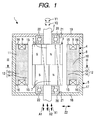
- FIG. 1 is an illustrated fragmentary sectional view of a brushless motor 1 according to one embodiment of the invention.
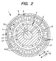
- FIG. 2 is an illustrated sectional view of the brushless motor 1 taken on line II-II,
- FIG. 3 is a schematic perspective view of a rotor 3, and
- FIG. 4 is an enlarged view of a part of FIG. 2 .
- the brushless motor 1 includes an annular rotor 3 joined to a rotation shaft 2 to rotate with the rotation shaft 2, an annular stator 4 surrounding the rotor 3, and a cylindrical frame 5 for housing the rotor 3 and the stator 4.
- the rotor 3 includes an annular rotor core 6 jointed to the rotation shaft 2 coaxially and a plurality of segment magnets 7 attached on the outer periphery of the rotor core 6, for example, with an adhesive, etc.
- Each of the segment magnets 7 has the same shape, and each shaped like a rectangle on a plan view as shown in FIG. 1 .
- the segment magnets 7 are arranged so that a length direction A1 is parallel with an axial direction X1 of the rotor core 6.
- the segment magnets 7 are stacked at n stages (where "n" is an integer of two or more; in the embodiment, n is two) in the axial direction X1 of the rotor core 6.
- the segment magnets 7 configuring each stage are arranged with an equal spacing in a circumferential direction Y1 of the rotor core 6 as shown in FIG. 2 .
- eight segment magnets 7 are arranged with an equal spacing in the circumferential direction Y1 of the rotor core 6.
- the number of the segment magnets 7 at each stage is not limited to eight and can take any other integer of two or more.
- the segment magnets 7 at the first stage (upper stage) and the segment magnets 7 at the second stage (lower stage) are overlapped in view of the axial direction X1 at a position where the rotor core 6 is divided into two equal parts in the axial direction X1.
- the segment magnets 7 having the same magnetic poles of the outer surfaces, overlapping in the axial direction X1 are shifted in phase in the circumferential direction Y1 of the rotor core 6 at a predetermined phase shift angle (mechanical angle). That is, the segment magnets 7 has a so-called stage skew arrangement with a skew angle ⁇ corresponding to the predetermined phase shift angle.
- the skew angle as the whole of the segment magnets 7 is (n x ⁇ ).
- the stage skew arrangement of the skew angle ⁇ is applied to the segment magnets 7, whereby the substitution effect of a rotor including skew-polarized ring magnets at the skew angle ⁇ ' is obtained.
- the segment magnets 7 are polarized after the segment magnets 7 are attached on the rotor core 6. As shown in FIG. 1 , the outer surfaces of the segment magnets 7 adjacent in the circumferential direction Y1 of the rotor core 6 are polarized to different magnetic poles.
- the rotor 3 has a plurality of magnetic poles of the segment magnets 7. As the magnetic poles at each stage, N and S poles are alternated in the circumferential direction Y1 of the rotor core 6. In the embodiment, the eight segment magnets 7 are arranged at each stage and therefore the number of magnetic poles P is eight.
- each segment magnet 7 has a predetermined effective pole angular aperture ⁇ (electrical angle) on the outer peripheral surface of the rotor core 6.
- the "effective pole angular aperture ⁇ " is an electrical angle corresponding to an angle (mechanical angle) formed by a line L3 and a line L4.
- the lines L3 and L4 connect end parts of the each segment magnet 7 in the circumferential direction Y1 of the inner surface of the each segment magnet 7 to the center of the rotor core 6 respectively.
- the stator 4 includes an annular stator core 8 and a plurality of coils 9 wound around the stator core 8.
- the stator core 8 is a magnetic green compact formed of a powder material having a soft magnetic material, for example.
- the shape of the stator core 8 is made symmetrical with an axial center portion 10 as the boundary.
- the axial length of the stator core 8 is made almost equal to the axial length of the rotor 3.
- the stator core 8 includes an annular yoke 11 and teeth 12 projected from the inner periphery of the yoke 11 toward the inside in a radial direction Z2 of the stator core 8.
- twelve teeth 12 are provided, for example.
- the teeth 12 are arranged annularly with an equal spacing in a circumferential direction Y2 of the stator core 8.
- a slot S is formed between the adjacent teeth 12.
- the number of the slots is 12. That is, the brushless motor 1 according to the embodiment is an eight-pole, 12-slot motor.
- Each of the teeth 12 has a roughly T shape in cross section and has a radial extension part 13 extending from the inner periphery of the yoke 11 to the inside in the radial direction of the yoke 11 and a circumferential extension part 14 joined to the radial extension part 13 and extending along the circumferential direction of a circle concentric with the yoke 11.
- Each coil 9 is wound around the outer periphery of the radial extension part 13 of the corresponding tooth 12.
- an axial extension part 15 extending outward in an axial direction X2 of the stator core 8 is provided at the tip of each tooth 12 with respect to the radial direction Z2 of the stator core 8. That is, the circumferential extension part 14 of each tooth 12 forms the tip of the tooth 12, and the end part with respect to the axial direction X2 of each circumferential extension part 14 is extended outward in the axial direction X2 and forms the axial extension part 15.
- each end part of the yoke 11 with respect to the axial direction X2 is also extended outward in the axial direction X2 and forms an axial extension part 16.
- the axial extension part 15 of the tooth 12 and the axial extension part 16 of the yoke 11 are opposed to each other with a spacing in the radial direction Z2 of the stator core 8.
- the frame 5 includes a tubular portion 17 and a pair of end walls 18 and 19 arranged in end parts of the tubular portion 17.
- the stator core 8 is fixed to the inner periphery of the tubular portion 17 by press fitting, for example.
- Each of the end walls 18 and 19 is formed with an insertion hole 20 through which the rotation shaft 2 is inserted.
- Each insertion hole 20 is formed with a bearing retention part 21 for retaining a bearing 22.
- the rotation shaft 2 is supported on the frame 5 for rotation through the bearings 22 retained in the bearing retention parts 21.
- FIGs. 5A and 5B are illustrated developed views of developing the rotor 3 in the circumferential direction Y1.
- one of the features of the invention is that the number of the magnetic poles P at each stage, the effective pole angular aperture ⁇ (electrical angle), and the skew angle ⁇ are set so that the following expression is satisfied: 2 x ⁇ / P + ⁇ ⁇ 360 / P
- the term (2 x ⁇ /P) in this expression is the mechanical angle corresponding to the effective pole angular aperture ⁇ and is equivalent to a width W1 of one segment magnet 7 with respect to the circumferential direction Y1 of the rotor core 6 shown in FIG. 5A .
- the skew angle ⁇ in the expression is equivalent to a shift amount W2 in the circumferential direction Y1 of the rotor core 6 at the corresponding magnetic poles of the segment magnets 7 at the adjacent stages (the first and second stages) shown in FIG. 5A .
- the term (360/P) in the expression is equivalent to a theoretical width W3 of one pole with respect to the circumferential direction Y1 of the rotor core 6 shown in FIG. 5A .
- the sum of the width W1 of one segment magnet 7 with respect to the circumferential direction Y1 of the rotor core 6 and the shift amount W2 in the circumferential direction Y1 of the rotor core 6 at the corresponding magnetic poles of the segment magnets 7 at the adjacent stages becomes smaller than the theoretical width W3 of one pole with respect to the circumferential direction Y1 of the rotor core 6. Accordingly, it is made possible to properly polarize unpolarized segment magnets 7 attached on the rotor core 6.
- one segment magnet 7 and a part of the segment magnet 7 (indicated by the dashed-two dotted line) adjacent to that segment magnet 7 in the circumferential direction Y1 are arranged at each stage in the hatched area in FIG. 5B .
- the segment magnets 7 are stacked, whereby the skew angle ⁇ ' when ring magnets are skew-polarized is artificially accomplished and moreover as the expression is satisfied, it is made possible substantially to polarize the unpolarized segment magnets 7 after they are arranged on the rotor core 6. Since the segment magnets 7 can be arranged on the rotor core 6 in an unpolarized state, the productivity of the brushless motor 1 is improved. That is, the segment magnets 7 are not magnetized and thus can be arranged on the rotor core 6 with good position accuracy.
- FIGs. 6A and 6B are drawings to describe cogging torque in the brushless motor 1.
- FIG. 6A shows the rotor 3 and the stator 4 illustratedly.
- FIG. 6B shows change in cogging torque relative to the rotation position of the rotor 3. That is, waveforms W1, W2, W3, and W4 show change in cogging torque relative to the rotation positions of the rotor 3 at predetermined axial positions of the brushless motor 1.
- the up and down direction in FIG. 6B corresponds to the magnitude of the cogging torque.
- the waveform W1 shows change in cogging torque at an axial position P1 corresponding to the upper axial extension part 15 in FIG. 6A
- the waveform W4 shows change in cogging torque at an axial position P4 corresponding to the lower axial extension part 15 in FIG. 6A
- the waveform W2 shows change in cogging torque at an axial position P2 corresponding to the axial center portion 10 of the status core 8 and the segment magnets 7 at the first stage
- the waveform W3 shows change in cogging torque at an axial position P3 corresponding to the axial center portion 10 of the status core 8 and the segment magnets 7 at the second stage.
- the waveforms W1 and W4 are equal waveforms out of phase with each other by 180 degrees. Therefore, the cogging torque at the axial position P1 is canceled out by the cogging torque at the axial position P4.
- the waveforms W2 and W3 are equal waveforms out of phase with each other by 180 degrees. Therefore, the cogging torque at the axial position P2 is canceled out by the cogging torque at the axial position P3.
- FIG. 7 is an illustrated fragmentary sectional view of a brushless motor 1a according to another embodiment of the invention. Components identical with or similar to those previously described with reference to FIGs. 1 to 6B are denoted by the same reference numerals in FIG. 7 and will not be discussed again.
- the embodiment differs from the embodiment described above mainly in that a stator core 108 is formed using different types of materials and the material of the same type is arranged symmetrically with an axial center portion 10 of the stator core 108 as the boundary.
- the stator core 108 is divided into three parts in an axial direction X2.
- the stator core 108 is configured by a pair of green compact cores 108a and 108a formed of magnetic green compacts and a laminated core 108b formed of a laminated steel plate.
- the laminated steel plate is provided by laminating and fixing in the axial direction X2 a plurality of thin sheets each formed by stamping a magnetic steel sheet into a predetermined shape.
- a silicon steel plate having a surface subjected to insulating treatment, etc. can be used as the magnetic steel sheet.
- the laminated core 108b is arranged in an intermediate part of the stator core 108 in the axial direction thereof.
- the green compact cores 108a and 108a are arranged at end parts of the laminated core 108b and are fixed to the end parts.
- the shape of the laminated core 108b is symmetrical with the axial center portion 10 as the boundary.
- the green compact cores 108a and 108a are of the same shape and are arranged symmetrically with the axial center portion 10 as the boundary.
- the shape of the laminated core 108b is made symmetrical with the axial center portion 10 as the boundary
- the green compact cores 108a and 108a are arranged symmetrically with the axial center portion 10 as the boundary
- segment magnets 7 involve a stage skew arrangement, so that the cogging torque at each axial position of the brushless motor 1 a is canceled out by the cogging torque at the corresponding axial position and the cogging torque as the whole brushless motor 1 a is theoretically zero at all times. Accordingly, the noise and vibration of the brushless motor 1 are reduced.
- FIG. 8 is an illustrated fragmentary sectional view of a brushless motor 1b according to still another embodiment of the invention.
- FIGs. 9A and 9B are drawings to describe cogging torque in the brushless motor 1b in FIG. 8 .
- Components identical with or similar to those previously described with reference to FIGs. 1 to 6B are denoted by the same reference numerals in FIGs. 8 , 9A and 9B and will not be discussed again.
- the embodiment differs from the embodiment previously described with reference to FIGs. 1 to 6B mainly in that magnetic poles of a rotor 203 has overhang parts (first overhang part 23 and second overhang part 24) overhanging outward in an axial direction X1 of a rotor core 6 so as not to be opposed to a stator core 208.
- the upper end part of each of segment magnets 7 making up a first stage is overhung upward in the axial direction X1 and forms the first overhang part 23.
- the first overhang part 23 is not opposed to the stator core 208 with respect to a radial direction Z1 of the rotor core 6.
- each of the segment magnets 7 making up a second stage is overhung downward in the axial direction X1 and forms the second overhang part 24.
- the second overhang part 24 is not opposed to the stator core 208 with respect to a radial direction Z1 of the rotor core 6.
- a length B1 of the rotor core 6 relative to the axial direction X1 is made larger than an axial length B2 of the stator core 208 (B1>B2).
- the length of the first overhang part 23 relative to the axial direction X1 of the rotor core 6 and that of the second overhang part 24 relative to the axial direction X1 of the rotor core 6 are made equal to each other.
- the stator core 208 is formed of a laminated steel plate.
- the shape of the stator core 208 is made symmetrical with an axial center portion 10 as the boundary.
- a waveform W11 shows change in cogging torque at an axial position P11 corresponding to the axial upper end part of the stator core 208
- a waveform W14 shows change in cogging torque at an axial position P14 corresponding to the axial lower end part of the stator core 208.
- the waveform W12 shows change in cogging torque at an axial position P12 corresponding to the axial center portion 10 of the status core 208 and the segment magnets 7 at the first stage
- the waveform W13 shows change in cogging torque at an axial position P13 corresponding to the axial center portion 10 of the status core 208 and the segment magnets 7 at the second stage.
- the amplitude of the waveform W11 and the amplitude of the waveform W14 are larger than the amplitude of the waveform W12 and the amplitude of the waveform W13, because the magnetic flux from a part of each segment magnet 7 at the first stage opposed to the axial upper end part of the stator core 208 and the magnetic flux from the first overhang part 23 enter the axial upper end part and concentrate thereon, as indicated by arrows in FIG. 9A .
- the magnetic flux from a part of each segment magnet 7 at the second stage opposed to the axial lower end part of the stator core 208 and the magnetic flux from the second overhang part 24 enter the axial lower end part and concentrate thereon.
- the waveforms W11 and W14 are equal waveforms out of phase with each other by 180 degrees.
- the waveforms W12 and W13 are equal waveforms out of phase with each other by 180 degrees. Therefore, the cogging torque at each axial position of the brushless motor 1 b is canceled out by the cogging torque at the corresponding axial position and the cogging torque as the whole brushless motor 1b is theoretically zero at all times.
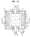
- FIG. 10 is an illustrated fragmentary sectional view of a brushless motor 1 c according to a reference example.
- FIG. 11 is an illustrated sectional view of the brushless motor 1 c taken on line XI-XI in FIG. 10 .
- Components identical with or similar to those previously described with reference to FIGs. 1 to 6B are denoted by the same reference numerals in FIGs. 10 and 11 and will not be discussed again.
- the reference example differs from the embodiment previously described with reference to FIGs. 1 to 6B mainly in that a pair of ring magnets 25 and 26 is arranged on the outer periphery of a rotor core 6.
- the ring magnets 25 and 26 are of the same shape and are stacked at two stages in an axial direction X1 of the rotor core 6.
- the ring magnets 25 and 26 are fixed to the rotor core 6 coaxially.
- Each of the ring magnets 25 and 26 is a multipolar magnet having a plurality of magnetic poles and as the magnetic poles of the outer peripheral surface of each of the ring magnets 25 and 26, N and S poles are alternated in the circumferential direction of the ring magnet 25, 26.
- each of the ring magnets 25 and 26 has eight magnetic poles, for example.
- each of the ring magnets 25 and 26 is polarized in parallel in the axial direction of the ring magnet 25, 26.
- the boundary line between the magnetic poles of the outer peripheral surface of the ring magnet 25, 26 adjacent in the circumferential direction of the ring magnet 25, 26 is parallel in the axial direction of the ring magnet 25, 26.
- the ring magnets 25 and 26 are arranged on the rotor core 6 after they are polarized.
- each of the ring magnets 25 and 26 is formed on the inner periphery with a plurality of projections 27 extending in the axial direction of the ring magnet 25, 26.
- each of the ring magnets 25 and 26 is formed with as many projections 27 as the number of the magnetic poles of each of the ring magnets 25 and 26.
- the projections 27 are provided in a one-to-one correspondence with the magnetic poles of the ring magnet 25 or 26.
- Each projection 27 is arranged at the center of the corresponding magnetic pole with respect to the circumferential direction of the ring magnet 25, 26.
- Each projection 27 is arranged across the magnetic poles adjacent in the circumferential direction of the ring magnet 25, 26.
- the rotor core 6 is formed on the outer periphery with a plurality of recess parts 28 in a one-to-one correspondence with the projections 27 formed on the ring magnets 25 and 26.
- Each recess part 28 extends in the axial direction X1 of the rotor core 6.
- the ring magnets 25 and 26 are fixed to the outer periphery of the rotor core 6 in a state in which the projections 27 of the ring magnets 25 and 26 are fitted into the corresponding recess parts 28. Accordingly, the ring magnets 25 and 26 are positioned relative to the rotor core 6 with good accuracy.
- the ring magnet 25 at the first stage and the ring magnet 26 at the second stage are fixed to the rotor core 6 in a state in which they are shifted in phase in the circumferential direction Y1 of the rotor core 6.
- the ring magnet 26 at the second stage is shifted in the circumferential direction Y1 of the rotor core 6 relative to the ring magnet 25 at the first stage at the angle corresponding to the half period of the basic-order component of the cogging torque at the axial position corresponding to the ring magnet 25 at the first stage or 360 degrees/(6 x number of magnetic poles at each stage).
- the number of the magnetic poles at each stage is eight and therefore "360 degrees/(6 x number of magnetic poles at each stage)" is 7.5 degrees.
- the ring magnet 26 at the second stage is shifted in the circumferential direction Y1 of the rotor core 6 at "the angle corresponding to the half period of the basic-order component of the cogging torque" relative to the ring magnet 25 at the first stage, whereby the cogging torque at the axial position corresponding to the ring magnet 25 at the first stage can be canceled out by the cogging torque at the axial position corresponding to the ring magnet 26 at the second stage.
- the ring magnet 26 at the second stage is shifted in the circumferential direction Y1 of the rotor core 6 at 7.5 degrees relative to the ring magnet 25 at the first stage, whereby not only the cogging torque, but also the sixth component of torque ripple can be canceled out.
- the ring magnet 26 at the second stage is shifted in the circumferential direction Y1 of the rotor core 6 at a predetermined angle relative to the ring magnet 25 at the first stage, whereby the cogging torque, etc., at each axial position of the brushless motor 1c is canceled out by the cogging torque, etc., at the corresponding axial position. Accordingly, the cogging torque and the sixth component of torque ripple as the whole brushless motor 1 c are theoretically set to zero at all times.
- each of the stator cores 8, 108, and 208 may be made up of split cores split in the circumferential direction Y2.
- a brushless motor includes a stator and a rotor.
- the stator includes an annular stator core having teeth arranged with a spacing in a circumferential direction of the annular stator core; and coils wound around the teeth respectively.
- the rotor includes a rotor core and magnetic poles of segment magnets arranged annularly along a circumferential direction of the rotor core.
- the segment magnets are stacked at a plurality of stages in an axial direction of the rotor core. A length direction of each of the segment magnets is parallel with the axial direction of the rotor core.
Landscapes
- Engineering & Computer Science (AREA)
- Power Engineering (AREA)
- Permanent Field Magnets Of Synchronous Machinery (AREA)
- Permanent Magnet Type Synchronous Machine (AREA)
- Brushless Motors (AREA)
- Iron Core Of Rotating Electric Machines (AREA)
Applications Claiming Priority (1)
| Application Number | Priority Date | Filing Date | Title |
|---|---|---|---|
| JP2007197649A JP2009033927A (ja) | 2007-07-30 | 2007-07-30 | ブラシレスモータ |
Publications (1)
| Publication Number | Publication Date |
|---|---|
| EP2020733A2 true EP2020733A2 (de) | 2009-02-04 |
Family
ID=39707960
Family Applications (1)
| Application Number | Title | Priority Date | Filing Date |
|---|---|---|---|
| EP08161308A Withdrawn EP2020733A2 (de) | 2007-07-30 | 2008-07-29 | Bürstenloser Motor |
Country Status (3)
| Country | Link |
|---|---|
| US (1) | US7667364B2 (de) |
| EP (1) | EP2020733A2 (de) |
| JP (1) | JP2009033927A (de) |
Cited By (4)
| Publication number | Priority date | Publication date | Assignee | Title |
|---|---|---|---|---|
| CN103580324A (zh) * | 2012-08-01 | 2014-02-12 | 德昌电机(深圳)有限公司 | 永磁转子及具有该转子的永磁马达 |
| CN105830308A (zh) * | 2014-01-08 | 2016-08-03 | 三菱电机株式会社 | 旋转电机 |
| US10749409B2 (en) | 2016-06-22 | 2020-08-18 | Sheng-Lian Lin | Motor |
| US11837935B2 (en) | 2021-02-02 | 2023-12-05 | Black & Decker, Inc. | Canned brushless motor |
Families Citing this family (20)
| Publication number | Priority date | Publication date | Assignee | Title |
|---|---|---|---|---|
| JP5123008B2 (ja) * | 2008-03-05 | 2013-01-16 | 株式会社ミツバ | ブラシレスモータ |
| DE102011110752A1 (de) * | 2010-08-20 | 2012-03-15 | Johnson Electric S.A. | Bürstenloser Motor |
| JP5635921B2 (ja) * | 2011-01-26 | 2014-12-03 | 株式会社日立産機システム | モータユニットおよびこれを用いた回転電機、回転電機装置 |
| US9748807B2 (en) * | 2011-08-11 | 2017-08-29 | Zhongshan Broad-Ocean Motor Manufacturing Co., Ltd. | Motor |
| US20130038162A1 (en) * | 2011-08-11 | 2013-02-14 | Zhongshan Broad-Ocean Motor Manufacturing Co., Ltd | Motor |
| CN103296789A (zh) * | 2012-03-05 | 2013-09-11 | 德昌电机(深圳)有限公司 | 永磁电机及应用该永磁电机的无叶风扇 |
| TWI516000B (zh) | 2013-08-20 | 2016-01-01 | 林聖梁 | 馬達 |
| KR101893018B1 (ko) * | 2014-05-06 | 2018-08-29 | 성-리엔 린 | 모터 |
| JP6181237B1 (ja) | 2016-05-20 | 2017-08-16 | Dmg森精機株式会社 | ロータの製造方法およびロータ |
| KR20180105901A (ko) * | 2017-03-16 | 2018-10-01 | 엘지전자 주식회사 | 영구 자석 매립형 회전자, 영구 자석형 모터 및 압축기 |
| JP6916133B2 (ja) * | 2018-03-09 | 2021-08-11 | 株式会社ミツバ | ブラシレスモータ |
| JP7080702B2 (ja) | 2018-04-12 | 2022-06-06 | 株式会社ミツバ | モータ及びブラシレスワイパーモータ |
| JP7308441B2 (ja) * | 2019-02-07 | 2023-07-14 | パナソニックIpマネジメント株式会社 | 電動工具 |
| CN114128089B (zh) * | 2019-07-19 | 2022-12-06 | 三菱电机株式会社 | 励磁元件及电动机 |
| CN110829771A (zh) * | 2019-09-30 | 2020-02-21 | 珠海运控电机有限公司 | 无缝电枢绕组永磁同步电动机 |
| KR20210138934A (ko) * | 2020-05-13 | 2021-11-22 | 엘지이노텍 주식회사 | 모터 |
| CN111864939B (zh) * | 2020-07-22 | 2025-06-06 | 珠海格力电器股份有限公司 | 转子冲片、斜极转子及其生产方法、电机、电动汽车 |
| CN114421658B (zh) * | 2022-01-29 | 2024-07-23 | 西安交通大学 | 一种轴向交错式永磁电机 |
| JP7638434B2 (ja) * | 2022-02-16 | 2025-03-03 | 三菱電機株式会社 | 永久磁石回転子 |
| WO2025088786A1 (ja) * | 2023-10-27 | 2025-05-01 | 三菱電機株式会社 | モータ、送風機および空気調和装置 |
Citations (1)
| Publication number | Priority date | Publication date | Assignee | Title |
|---|---|---|---|---|
| JP2001359266A (ja) | 2000-06-13 | 2001-12-26 | Aichi Emerson Electric Co Ltd | ブラシレスdcモータの構造 |
Family Cites Families (8)
| Publication number | Priority date | Publication date | Assignee | Title |
|---|---|---|---|---|
| US7067948B2 (en) * | 2002-10-18 | 2006-06-27 | Mitsubishi Denki Kabushiki Kaisha | Permanent-magnet rotating machine |
| US6940198B2 (en) * | 2003-07-24 | 2005-09-06 | A. O. Smith Corporation | Brushless permanent magnet machine with reduced cogging and torque ripple and method of producing the same |
| US7327066B2 (en) * | 2005-03-01 | 2008-02-05 | Nidec Corporation | Motor and recording disk drive device provided with the same |
| JP4863061B2 (ja) * | 2006-05-12 | 2012-01-25 | 株式会社ジェイテクト | 電動モータ |
| JP4848842B2 (ja) * | 2006-05-29 | 2011-12-28 | 株式会社ジェイテクト | ブラシレスモータ及び電動パワーステアリング装置 |
| JP2008086064A (ja) * | 2006-09-26 | 2008-04-10 | Jtekt Corp | ブラシレスモータ |
| JP2008228390A (ja) * | 2007-03-09 | 2008-09-25 | Jtekt Corp | ブラシレスモータおよびそれを備えた電動パワーステアリング装置 |
| JP2008228457A (ja) * | 2007-03-13 | 2008-09-25 | Jtekt Corp | ブラシレスモータおよびそれを備える電動パワーステアリング装置 |
-
2007
- 2007-07-30 JP JP2007197649A patent/JP2009033927A/ja active Pending
-
2008
- 2008-07-17 US US12/174,851 patent/US7667364B2/en not_active Expired - Fee Related
- 2008-07-29 EP EP08161308A patent/EP2020733A2/de not_active Withdrawn
Patent Citations (1)
| Publication number | Priority date | Publication date | Assignee | Title |
|---|---|---|---|---|
| JP2001359266A (ja) | 2000-06-13 | 2001-12-26 | Aichi Emerson Electric Co Ltd | ブラシレスdcモータの構造 |
Cited By (11)
| Publication number | Priority date | Publication date | Assignee | Title |
|---|---|---|---|---|
| CN103580324A (zh) * | 2012-08-01 | 2014-02-12 | 德昌电机(深圳)有限公司 | 永磁转子及具有该转子的永磁马达 |
| CN103580324B (zh) * | 2012-08-01 | 2017-09-01 | 德昌电机(深圳)有限公司 | 永磁转子及具有该转子的永磁马达 |
| CN105830308A (zh) * | 2014-01-08 | 2016-08-03 | 三菱电机株式会社 | 旋转电机 |
| CN105830308B (zh) * | 2014-01-08 | 2018-06-29 | 三菱电机株式会社 | 旋转电机 |
| US10749409B2 (en) | 2016-06-22 | 2020-08-18 | Sheng-Lian Lin | Motor |
| US11837935B2 (en) | 2021-02-02 | 2023-12-05 | Black & Decker, Inc. | Canned brushless motor |
| US11855521B2 (en) | 2021-02-02 | 2023-12-26 | Black & Decker, Inc. | Brushless DC motor for a body-grip power tool |
| US11870316B2 (en) | 2021-02-02 | 2024-01-09 | Black & Decker, Inc. | Brushless motor including a nested bearing bridge |
| US11876424B2 (en) | 2021-02-02 | 2024-01-16 | Black & Decker Inc. | Compact brushless motor including in-line terminals |
| US11955863B2 (en) | 2021-02-02 | 2024-04-09 | Black & Decker Inc. | Circuit board assembly for compact brushless motor |
| US12261497B2 (en) | 2021-02-02 | 2025-03-25 | Black & Decker Inc. | High-power motor for a body-grip power tool |
Also Published As
| Publication number | Publication date |
|---|---|
| US7667364B2 (en) | 2010-02-23 |
| US20090033174A1 (en) | 2009-02-05 |
| JP2009033927A (ja) | 2009-02-12 |
Similar Documents
| Publication | Publication Date | Title |
|---|---|---|
| US7667364B2 (en) | Brushless motor | |
| CN110808643B (zh) | 旋转电机用定子铁心及旋转电机 | |
| US8704412B2 (en) | Rotary electric machine | |
| JP5478136B2 (ja) | 永久磁石式同期モータ | |
| US7528519B2 (en) | Permanent magnet rotary motor | |
| CN103493338B (zh) | 永磁铁式旋转电机 | |
| EP2485371A2 (de) | Rotierende elektrische Maschine | |
| JP2008193809A (ja) | 埋込磁石型モータ | |
| JPH10215557A (ja) | モータ | |
| US20180262081A1 (en) | Electric motor including stator assembly and method of assembly thereof | |
| JP4633978B2 (ja) | ブラシレスモータ及びブラシレスモータのステータ | |
| JP2002058184A (ja) | ロータの構造及び電動機 | |
| JP2002112521A (ja) | ステップモータのロータ構造 | |
| JP2002136094A (ja) | ステッピングモータ | |
| JP2011097756A (ja) | ステッピングモータのステータヨークおよびステッピングモータ | |
| JP5317228B2 (ja) | 回転電機 | |
| JP2001231240A (ja) | ステッピングモータ | |
| JP2003153474A (ja) | 回転電機の積層鉄心 | |
| JP2012005311A (ja) | 回転電機 | |
| JPH083187Y2 (ja) | ブラシレスモータ | |
| JP2003009499A (ja) | クローポール型ステッピングモータのモータ構造 | |
| JP2011114989A (ja) | 回転電機 | |
| JP7768323B2 (ja) | ロータ及び回転電機 | |
| EP1947753A1 (de) | Elektrische drehmaschine | |
| JP2021044885A (ja) | 積層鉄心の製造方法、電気機械の製造方法、積層鉄心の製造装置、及び電気機械 |
Legal Events
| Date | Code | Title | Description |
|---|---|---|---|
| PUAI | Public reference made under article 153(3) epc to a published international application that has entered the european phase |
Free format text: ORIGINAL CODE: 0009012 |
|
| AK | Designated contracting states |
Kind code of ref document: A2 Designated state(s): AT BE BG CH CY CZ DE DK EE ES FI FR GB GR HR HU IE IS IT LI LT LU LV MC MT NL NO PL PT RO SE SI SK TR |
|
| AX | Request for extension of the european patent |
Extension state: AL BA MK RS |
|
| STAA | Information on the status of an ep patent application or granted ep patent |
Free format text: STATUS: THE APPLICATION HAS BEEN WITHDRAWN |
|
| 18W | Application withdrawn |
Effective date: 20100917 |