EP2020595B1 - Erfassungsverfahren eines Fahrzeugs für ein Störphänomen der Sicht - Google Patents
Erfassungsverfahren eines Fahrzeugs für ein Störphänomen der Sicht Download PDFInfo
- Publication number
- EP2020595B1 EP2020595B1 EP08160818.4A EP08160818A EP2020595B1 EP 2020595 B1 EP2020595 B1 EP 2020595B1 EP 08160818 A EP08160818 A EP 08160818A EP 2020595 B1 EP2020595 B1 EP 2020595B1
- Authority
- EP
- European Patent Office
- Prior art keywords
- vehicle
- visibility
- camera
- image
- cam
- Prior art date
- Legal status (The legal status is an assumption and is not a legal conclusion. Google has not performed a legal analysis and makes no representation as to the accuracy of the status listed.)
- Active
Links
Images


Classifications
-
- G—PHYSICS
- G01—MEASURING; TESTING
- G01N—INVESTIGATING OR ANALYSING MATERIALS BY DETERMINING THEIR CHEMICAL OR PHYSICAL PROPERTIES
- G01N21/00—Investigating or analysing materials by the use of optical means, i.e. using sub-millimetre waves, infrared, visible or ultraviolet light
- G01N21/17—Systems in which incident light is modified in accordance with the properties of the material investigated
- G01N21/47—Scattering, i.e. diffuse reflection
- G01N21/49—Scattering, i.e. diffuse reflection within a body or fluid
- G01N21/53—Scattering, i.e. diffuse reflection within a body or fluid within a flowing fluid, e.g. smoke
- G01N21/538—Scattering, i.e. diffuse reflection within a body or fluid within a flowing fluid, e.g. smoke for determining atmospheric attenuation and visibility
-
- B—PERFORMING OPERATIONS; TRANSPORTING
- B60—VEHICLES IN GENERAL
- B60Q—ARRANGEMENT OF SIGNALLING OR LIGHTING DEVICES, THE MOUNTING OR SUPPORTING THEREOF OR CIRCUITS THEREFOR, FOR VEHICLES IN GENERAL
- B60Q1/00—Arrangement of optical signalling or lighting devices, the mounting or supporting thereof or circuits therefor
- B60Q1/0017—Devices integrating an element dedicated to another function
- B60Q1/0023—Devices integrating an element dedicated to another function the element being a sensor, e.g. distance sensor, camera
-
- B—PERFORMING OPERATIONS; TRANSPORTING
- B60—VEHICLES IN GENERAL
- B60Q—ARRANGEMENT OF SIGNALLING OR LIGHTING DEVICES, THE MOUNTING OR SUPPORTING THEREOF OR CIRCUITS THEREFOR, FOR VEHICLES IN GENERAL
- B60Q1/00—Arrangement of optical signalling or lighting devices, the mounting or supporting thereof or circuits therefor
- B60Q1/02—Arrangement of optical signalling or lighting devices, the mounting or supporting thereof or circuits therefor the devices being primarily intended to illuminate the way ahead or to illuminate other areas of way or environments
- B60Q1/04—Arrangement of optical signalling or lighting devices, the mounting or supporting thereof or circuits therefor the devices being primarily intended to illuminate the way ahead or to illuminate other areas of way or environments the devices being headlights
- B60Q1/14—Arrangement of optical signalling or lighting devices, the mounting or supporting thereof or circuits therefor the devices being primarily intended to illuminate the way ahead or to illuminate other areas of way or environments the devices being headlights having dimming means
- B60Q1/1415—Dimming circuits
- B60Q1/1423—Automatic dimming circuits, i.e. switching between high beam and low beam due to change of ambient light or light level in road traffic
- B60Q1/143—Automatic dimming circuits, i.e. switching between high beam and low beam due to change of ambient light or light level in road traffic combined with another condition, e.g. using vehicle recognition from camera images or activation of wipers
-
- B—PERFORMING OPERATIONS; TRANSPORTING
- B60—VEHICLES IN GENERAL
- B60Q—ARRANGEMENT OF SIGNALLING OR LIGHTING DEVICES, THE MOUNTING OR SUPPORTING THEREOF OR CIRCUITS THEREFOR, FOR VEHICLES IN GENERAL
- B60Q1/00—Arrangement of optical signalling or lighting devices, the mounting or supporting thereof or circuits therefor
- B60Q1/26—Arrangement of optical signalling or lighting devices, the mounting or supporting thereof or circuits therefor the devices being primarily intended to indicate the vehicle, or parts thereof, or to give signals, to other traffic
- B60Q1/2603—Attenuation of the light according to ambient luminiosity, e.g. for braking or direction indicating lamps
-
- B—PERFORMING OPERATIONS; TRANSPORTING
- B60—VEHICLES IN GENERAL
- B60R—VEHICLES, VEHICLE FITTINGS, OR VEHICLE PARTS, NOT OTHERWISE PROVIDED FOR
- B60R16/00—Electric or fluid circuits specially adapted for vehicles and not otherwise provided for; Arrangement of elements of electric or fluid circuits specially adapted for vehicles and not otherwise provided for
- B60R16/02—Electric or fluid circuits specially adapted for vehicles and not otherwise provided for; Arrangement of elements of electric or fluid circuits specially adapted for vehicles and not otherwise provided for electric constitutive elements
- B60R16/023—Electric or fluid circuits specially adapted for vehicles and not otherwise provided for; Arrangement of elements of electric or fluid circuits specially adapted for vehicles and not otherwise provided for electric constitutive elements for transmission of signals between vehicle parts or subsystems
- B60R16/0237—Electric or fluid circuits specially adapted for vehicles and not otherwise provided for; Arrangement of elements of electric or fluid circuits specially adapted for vehicles and not otherwise provided for electric constitutive elements for transmission of signals between vehicle parts or subsystems circuits concerning the atmospheric environment
-
- G—PHYSICS
- G06—COMPUTING OR CALCULATING; COUNTING
- G06V—IMAGE OR VIDEO RECOGNITION OR UNDERSTANDING
- G06V20/00—Scenes; Scene-specific elements
- G06V20/50—Context or environment of the image
- G06V20/56—Context or environment of the image exterior to a vehicle by using sensors mounted on the vehicle
- G06V20/58—Recognition of moving objects or obstacles, e.g. vehicles or pedestrians; Recognition of traffic objects, e.g. traffic signs, traffic lights or roads
-
- B—PERFORMING OPERATIONS; TRANSPORTING
- B60—VEHICLES IN GENERAL
- B60Q—ARRANGEMENT OF SIGNALLING OR LIGHTING DEVICES, THE MOUNTING OR SUPPORTING THEREOF OR CIRCUITS THEREFOR, FOR VEHICLES IN GENERAL
- B60Q2300/00—Indexing codes for automatically adjustable headlamps or automatically dimmable headlamps
- B60Q2300/30—Indexing codes relating to the vehicle environment
- B60Q2300/31—Atmospheric conditions
- B60Q2300/312—Adverse weather
Definitions
- the present invention relates to a method for detecting a visibility disturbing phenomenon, and to a detection device making it possible to implement said method.
- the document EP 1,715,456 describes a method of detecting night fog in a road scene at the front of the vehicle, comprising the operations of lighting the road scene by the projectors of the vehicle, of acquisition of several successive images of the road scene, extraction in these images of the luminous halo created by the projectors, approximation of the shape of this halo, comparison with the closest approximate elliptical curve, and deduction of the presence or absence of fog.
- the document EP 1 498 721 describes a method of detecting fog, comprising a digital camera detecting the environment around the vehicle, and an image processing system which compares the brightness of each pixel of the camera with a predetermined minimum value and deduces the presence of fog if none of the pixels have a brightness lower than the predetermined value.
- the document EP 1,298,481 describes a night vision device, comprising an infrared transmitter, a detector and a display device.
- the transmitter comprises one or more diodes emitting pulses, being controlled by a driver which simultaneously controls the detector or a camera. This document does not deal with fog.
- the document EP 1,553,429 describes a system for detecting traffic conditions on a road (weather conditions or obstacle detection), mounted on a motor vehicle, comprising at least one light projector comprising a first light source emitting a visible light beam and at least one source of Modular light, in particular at high frequency, emitting an infrared light beam towards a road scene, and at least one camera for taking images of the road scene.
- the document EP 1,790,541 describes a device for detecting dirt on a windshield of a motor vehicle, using two cameras and an image processing system.
- the document FR 2 847 367 describes a method and a passive device for determining the visibility distance in the presence of an element disturbing visibility such as fog, which does not comprise emission of light beam.
- the object of the present invention is to detect a disturbing phenomenon of visibility.
- such a method has the advantage of carrying out an analysis of a visibility disturbing phenomenon by means of an image captured by a video camera. No complex electronic device is necessary. In addition, the use of a video camera is not very expensive.
- a third subject of the invention relates to a computer program product according to claim 5 comprising one or more sequences of instructions executable by an information processing unit, the execution of said sequences of instructions allowing a setting implementing the method according to any one of the preceding characteristics.
- the method for detecting a disturbance phenomenon of visibility allows such detection and is described in an embodiment not limiting to the Fig. 1 .
- the detection is done from a detection device on board a vehicle V comprising a video camera described below.
- a light beam FX is emitted from said vehicle V, the light beam being emitted in the field of vision of the camera CAM of vehicle V.
- the beam FX is a near infrared beam of wavelength 850 nm. This avoids creating untimely light effects on the rear of the vehicle in the presence of a disturbing phenomenon G, and thus disturbing the following drivers. In addition, this makes it possible to be compatible with the detection spectrum of the CAM camera as we will see below.
- the beam FX is narrow. In a nonlimiting example, it has an opening of 4 °. This allows not to have a loss of power. There is thus a concentration of the energy in the light beam FX and a detection of a disturbing phenomenon at greater distances.
- the light beam FX is generated by a DIOD light source described below.
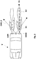
- the Fig. 2 shows an example of a light beam FX generated by a light source DIOD and emitted in the field of vision CAM_V of the camera CAM of the vehicle V.
- the light beam FX is emitted at the rear of the vehicle V.
- two sprays of water G1 and G2 are shown and are illuminated by the light beam FX.
- the Fig. 3 shows a top view of the Fig. 2 . You can see the location of the DIOD light source in a rear light and the location of the CAM camera between the two rear lights.
- the generation of the light beam FX is done as soon as the rear lights are triggered. It therefore works continuously as soon as these lights are switched on. This makes it possible to be sure of being able to detect a disturbing phenomenon such as a spray of water as soon as it rains or when the roadway is wet and to adapt the lighting of the rear lights accordingly according to the nature of the disturbing phenomenon.
- a second step 2) an image I is acquired by the camera of the vehicle V.
- the video camera CAM being placed, in the example taken, at the rear of the vehicle V, the acquired image I corresponds to the environment of the vehicle V located in the field of the camera CAM and therefore to the rear of vehicle V. We will therefore detect a disturbing phenomenon G located at the rear of vehicle V.
- the CAM camera is placed near one of the rear lights of vehicle V.
- the light coming from the light beam FX emitted from one of the rear lights is scattered in the presence of particles of the disturbing phenomenon G suspended in the atmosphere (after the passage of the wheels over a wet surface for example).
- the wavelength of this light beam being compatible with the analysis spectrum of the CAM camera, and the constituent particles of the disturbing phenomenon G being located in the field of vision of the CAM camera, it is then possible to capture an image integrating the scattered light into the disturbing phenomenon G.
- this image acquisition step may not be included in the method described, but may be part of another method executed upstream of the method described.
- first and second stages can be carried out in parallel.
- a third step 3 the presence and the nature of a visibility disturbing phenomenon G is determined from the image I acquired by the camera CAM.
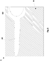
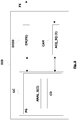
- FIG. 4 Two nonlimiting examples of an image I acquired by the CAM camera are represented on the Fig. 4 and Fig. 5 .
- the white part represents the light scattered at night with the light beam FX, while the hatched part denoted B represents the environment, here at the rear, of the vehicle V in the field of the CAM camera not lit by the light beam FX .
- the example of the Fig. 4 represents the environment at the rear of the vehicle V in the presence of rain, without obstacle O in the field CAM_V of the camera CAM, the image I showing packets of water P1 and P2 revealing the presence of a phenomenon disruptive G, such as a spray of water, caused by aerodynamic turbulence behind vehicle V.
- a phenomenon disruptive G such as a spray of water
- the example of the Fig. 5 represents the environment behind the vehicle V in the presence of fog, with an obstacle O (such as a follower vehicle).
- an external light source SO appears in the field, to the right of image I. It may be an obstacle O such as a headlight of a following vehicle or such as a stationary source in the landscape.
- the detection and characterization of this type of light source in the image is easy, using for example methods of tracking image objects (“tracking” in English) based for example on the detection of shadows to put highlight the contours of a follower vehicle. As these methods are well known to those skilled in the art, they are not described here.
- the information on the presence of the following vehicle may be used for optimal management of the intensity of the signaling functions.
- the intensity of the position lights for example is characterized at several standard points. According to a European standard (ECE R7), the intensity of these points varies from 0.05cd to 4cd minimum depending on the points. The maximum allowed is 12cd for a single light, 17cd for a set of lights. Thus, if we detect water then we increase the intensity of the lights, but if we detect water and the presence of a nearby following vehicle we increase the intensity of the lights accordingly (this is that is, less than in the absence of this vehicle so as not to be dazzling and less than in the presence of a distant vehicle).
- the characterization of the nature of the disturbing phenomenon is based on the homogeneity and the particle size of the scattered light. Thanks to these two parameters, we can thus discriminate between water and fog.
- the advantage of discriminating water and fog is to be able to activate a specific signaling in the event of the presence of fog, i.e. the fog lights, to increase the intensity of the rear lights in the event of presence of a spray of water for example etc.
- the determination of the homogeneity of the scattered light is known to a person skilled in the art.
- texture analysis methods such as the co-occurrence matrices and more particularly its homogeneity criterion. Since this method is well known to those skilled in the art, it is therefore not described in detail here.
- the determination of the particle size (texture attribute) of the scattered light is also known to those skilled in the art. It can in a nonlimiting example be based on an analysis of the texture of an image I using probabilistic approaches such as the co-occurrence matrices and / or frequency approaches such as the Fourier transform, the wavelet decomposition. .etc. As these methods are known to those skilled in the art, they are therefore not described in detail here.
- the disturbing phenomenon G is illuminated and visible as well as the obstacle O.
- the light beam FX if on the acquired image I, the light beam FX reveals zones which are not homogeneous and whose texture (given by the particle size) is not smooth, we conclude in the presence of packets water (in the case of a wet roadway with or without rain). At this time, the intensity of the lights can be increased.
- the light beam FX reveals a homogeneous continuous zone and whose texture (given by the particle size) is smoother, one could conclude in the presence of fog (unless one is in the presence of fine rain without generating a spray of water). At this time the fog lights can be turned on.
- a disturbing phenomenon G such as fog
- no movement will be detected on the sequence SQ of acquired images I
- a disturbing phenomenon such as water
- This movement follow-up is based on a follow-up (“tracking”) of the illuminated zones on the SQ sequence of images I. Since such movement follow-up is known to those skilled in the art, it is not described here.
- This movement tracking is particularly useful for discriminating water fog, when there is no spray of generated water (in case of light rain for example) or when the vehicle is traveling at low speed.
- the acquired image I indeed presents a homogeneous continuous zone.
- a visibility disturbing phenomenon G is detected and its nature defined, adequate processing CD in real time on the vehicle V can be executed.
- this fourth step is carried out as the video images are processed by the method described above.
- the adequate processing CD such as for example the automatic adaptation of the lighting of the rear lights, is executed in real time since it is carried out after each detection of a disturbing phenomenon, a detection being carried out with each acquisition of image I.
- the method of the invention is implemented by a DISP detection device shown in the Fig. 6 .
- the control unit UC also makes it possible to control the light source DIOD and the camera CAM and to control (automatic adaptation of the lighting of the lights, automatic lighting of the lights) or carry out (sending of an alert signal ) adequate CD treatment.
- the detection device DISP can also include the video camera CAM making it possible to acquire an image I as illustrated in the Fig. 6 .
- the control unit UC can also be located in the video camera CAM.
- the DIOD light source and the CAM camera are described in more detail below.
- the DIOD light source The DIOD light source.
- the DIOD light source is a LED type diode.
- a vehicle lighting and signaling system in the example taken from a rear light of vehicle V, due to the protection provided by the lens of the light
- a light beam generator composed of the infrared DIOD light source plus an optical projection system
- control electronics can be placed in the rear part of a light, which often has available volumes.
- This camera is for example of the VGA type of definition 640 * 480 (that is to say an acquired image I of 8 bits (per pixel) and of 640 columns and 480 lines) and includes a lens (not shown) for this purpose.
- the image I thus acquired is in full resolution.
- the video camera CAM acquires 10 images per second. It will be noted that a sequence of images SQ comprises between twenty images and a hundred images per second depending on the speed at which the vehicle V.
- the CAM camera being used for detecting the presence of a disturbing phenomenon G, it must be sensitive to the wavelength used for the light beam FX.
- cameras such as CMOS or CCD conventionally used in automotive applications will therefore be used because they are based on silicon and have a spectral response of 400 nm to 1100 nm approximately (range of wavelengths seen by the camera). This spectral response is therefore compatible with an infrared FX beam.
- the FX light beam will be seen by the CAM camera because it has a length wavelength (infrared here) included in the wavelength range to which the CAM camera is sensitive.
- the CAM_V field of the CAM camera cuts the light beam FX fairly close (between 1 and 5 meters) to the light source emitting DIOD of the light beam FX. This makes it possible to obtain precise information concerning the disturbing phenomena G located, in the example taken from the rear of the vehicle, and thus to be sure of detecting the presence of a phenomenon and in particular of a spray of water.
- the range of the CAM_V field of the camera is determined so as to cover an area where a disturbing phenomenon G can be generated (in the case of a shower of water). In a nonlimiting example, it is of the order 20 meters.
- the detection device DISP can comprise a computer program product PG comprising one or more sequences of instructions executable by an information processing unit such as a microprocessor, or a processing unit of a microcontroller , an ASIC, a computer, etc., the execution of said sequences of instructions allowing an implementation of the method described.
- an information processing unit such as a microprocessor, or a processing unit of a microcontroller , an ASIC, a computer, etc.
- Such a computer program PG can be written in writable non-volatile memory of ROM type or in rewritable non-volatile memory of type EEPROM or FLASH. Said PG computer program can be written into memory at the factory or loaded into memory or downloaded remotely into memory.
- the sequences of instructions can be sequences of machine instructions, or else sequences of a command language interpreted by the processing unit at the time of their execution.
- the computer program PG is written in a memory of the control unit UC of the device DISP.
- the description of the process is not limited to the embodiments and examples described above.
- the light beam FX emitted can be modulated.
- n is large (for example displaying 29 images without modulated light and the 30th modulated on a system capturing 30 images / second) it is possible to superimpose the "disturbing phenomenon detection" function on another function such as a parking assistance function, without altering the disturbing phenomenon detection function.
Landscapes
- Engineering & Computer Science (AREA)
- Mechanical Engineering (AREA)
- General Physics & Mathematics (AREA)
- Life Sciences & Earth Sciences (AREA)
- Physics & Mathematics (AREA)
- Biodiversity & Conservation Biology (AREA)
- Environmental Sciences (AREA)
- Biochemistry (AREA)
- Immunology (AREA)
- Pathology (AREA)
- Analytical Chemistry (AREA)
- Environmental & Geological Engineering (AREA)
- General Health & Medical Sciences (AREA)
- Chemical & Material Sciences (AREA)
- Health & Medical Sciences (AREA)
- Multimedia (AREA)
- Theoretical Computer Science (AREA)
- Lighting Device Outwards From Vehicle And Optical Signal (AREA)
- Traffic Control Systems (AREA)
- Investigating Or Analysing Materials By Optical Means (AREA)
- Investigating, Analyzing Materials By Fluorescence Or Luminescence (AREA)
Claims (5)
- Erfassungsverfahren eines Störphänomens der Sicht (G), umfassend die folgenden Schritte:- Ausgeben eines Lichtstrahls (FX) aus einem Fahrzeug (V), wobei der Lichtstrahl im Sichtfeld einer Kamera (CAM) des Fahrzeugs (V) ausgegeben wird; und- Bestimmen des Vorhandenseins und der Art eines Störphänomens der Sicht (G) aus mindestens einem von der Kamera (CAM) aufgenommenen Bild (I),dadurch gekennzeichnet, dass die Bestimmung der Art des Störphänomens der Sicht (G) in Abhängigkeit von der Homogenität und Granulometrie des Störphänomens der Sicht (G) auf dem Bild (I) erfolgt.
- Erfassungsverfahren nach einem der vorhergehenden Ansprüche, dadurch gekennzeichnet, dass die Bestimmung der Art des Störphänomens der Sicht (G) in Abhängigkeit von einer Bewegungsüberwachung des Störphänomens (G) erfolgt.
- Erfassungsverfahren nach einem der vorhergehenden Ansprüche, dadurch gekennzeichnet, dass der Lichtstrahl (FX) moduliert ist.
- Erfassungsvorrichtung (DISP) eines Störphänomens der Sicht (G), umfassend:- eine Lichtquelle (DIOD), die einen Lichtstrahl (FX) aus einem Fahrzeug (V) ausgibt, wobei der Lichtstrahl im Sichtfeld einer Kamera (CAM) des Fahrzeugs (V) ausgegeben wird; und- eine Steuereinheit (UC) zum Bestimmen des Vorhandenseins und der Art eines Störphänomens der Sicht (G) aus mindestens einem von der Kamera (CAM) aufgenommenen Bild (I), dadurch gekennzeichnet, dass die Steuereinheit (UC) die Art des Störphänomens der Sicht (G) in Abhängigkeit von der Homogenität und Granulometrie des Störphänomens der Sicht (G) auf dem Bild (I) bestimmt.
- Computerprogrammprodukt (PG), umfassend eine oder mehrere Sequenzen von Anweisungen, die von einer Informationsverarbeitungseinheit ausgeführt werden können, die Ausführung der Sequenzen von Anweisungen, dadurch gekennzeichnet ist, dass sie die Umsetzung des Verfahrens nach einem der vorhergehenden Ansprüche 1 bis 3 ermöglicht.
Applications Claiming Priority (1)
| Application Number | Priority Date | Filing Date | Title |
|---|---|---|---|
| FR0705715A FR2919727B1 (fr) | 2007-08-03 | 2007-08-03 | Procede de detection par un vehicule d'un phenomene perturbateur de visibilite |
Publications (2)
| Publication Number | Publication Date |
|---|---|
| EP2020595A1 EP2020595A1 (de) | 2009-02-04 |
| EP2020595B1 true EP2020595B1 (de) | 2020-01-08 |
Family
ID=39166954
Family Applications (1)
| Application Number | Title | Priority Date | Filing Date |
|---|---|---|---|
| EP08160818.4A Active EP2020595B1 (de) | 2007-08-03 | 2008-07-21 | Erfassungsverfahren eines Fahrzeugs für ein Störphänomen der Sicht |
Country Status (4)
| Country | Link |
|---|---|
| US (1) | US7920250B2 (de) |
| EP (1) | EP2020595B1 (de) |
| JP (1) | JP5356746B2 (de) |
| FR (1) | FR2919727B1 (de) |
Families Citing this family (24)
| Publication number | Priority date | Publication date | Assignee | Title |
|---|---|---|---|---|
| PL2023812T3 (pl) | 2006-05-19 | 2017-07-31 | The Queen's Medical Center | Układ śledzenia ruchu dla adaptacyjnego obrazowania w czasie rzeczywistym i spektroskopii |
| EP2172873B1 (de) | 2008-10-06 | 2018-08-15 | Mobileye Vision Technologies Ltd. | Bündelung von Fahrhilfssystemen |
| US9459515B2 (en) | 2008-12-05 | 2016-10-04 | Mobileye Vision Technologies Ltd. | Adjustable camera mount for a vehicle windshield |
| FR2953602B1 (fr) * | 2009-12-04 | 2012-07-27 | Valeo Vision | Systeme de detection d'obstacle pour vehicule |
| DE102010002488A1 (de) | 2010-03-02 | 2011-09-08 | Robert Bosch Gmbh | Verfahren und Vorrichtung zur Nebelerkennung mittels Spektroskopie |
| DE102010063017A1 (de) * | 2010-12-14 | 2012-06-14 | Robert Bosch Gmbh | Verfahren in einem Fahrerassistenzsystem zur Erkennung von Nässe auf einer Fahrbahn |
| WO2013032933A2 (en) | 2011-08-26 | 2013-03-07 | Kinecticor, Inc. | Methods, systems, and devices for intra-scan motion correction |
| US9305365B2 (en) | 2013-01-24 | 2016-04-05 | Kineticor, Inc. | Systems, devices, and methods for tracking moving targets |
| US9717461B2 (en) | 2013-01-24 | 2017-08-01 | Kineticor, Inc. | Systems, devices, and methods for tracking and compensating for patient motion during a medical imaging scan |
| US10327708B2 (en) | 2013-01-24 | 2019-06-25 | Kineticor, Inc. | Systems, devices, and methods for tracking and compensating for patient motion during a medical imaging scan |
| CN109008972A (zh) | 2013-02-01 | 2018-12-18 | 凯内蒂科尔股份有限公司 | 生物医学成像中的实时适应性运动补偿的运动追踪系统 |
| CN105324287B (zh) * | 2013-04-11 | 2018-07-06 | 伟摩有限责任公司 | 使用车载传感器检测天气条件的方法和系统 |
| WO2015148391A1 (en) | 2014-03-24 | 2015-10-01 | Thomas Michael Ernst | Systems, methods, and devices for removing prospective motion correction from medical imaging scans |
| CN106714681A (zh) | 2014-07-23 | 2017-05-24 | 凯内蒂科尔股份有限公司 | 用于在医学成像扫描期间追踪和补偿患者运动的系统、设备和方法 |
| US9943247B2 (en) | 2015-07-28 | 2018-04-17 | The University Of Hawai'i | Systems, devices, and methods for detecting false movements for motion correction during a medical imaging scan |
| JP6536372B2 (ja) * | 2015-11-16 | 2019-07-03 | 株式会社デンソーウェーブ | レーザレーダ装置の泥汚れ判定方法、泥汚れ判定装置、泥汚れ判定プログラム |
| CN108697367A (zh) | 2015-11-23 | 2018-10-23 | 凯内蒂科尓股份有限公司 | 用于在医学成像扫描期间跟踪并补偿患者运动的系统、装置和方法 |
| FR3058690B1 (fr) * | 2016-11-16 | 2019-11-01 | Peugeot Citroen Automobiles Sa | Systeme d'eclairage assiste pour vehicule et procede de formation d'une image hybride |
| US10246003B2 (en) | 2017-03-22 | 2019-04-02 | International Business Machines Corporation | Determination and setting of optimal intensity |
| EP3477548B1 (de) * | 2017-10-24 | 2020-02-19 | Axis AB | Verfahren und bilderfassungsvorrichtung zur detektion von nebel in einer szene |
| JP7252755B2 (ja) * | 2018-12-27 | 2023-04-05 | 株式会社小糸製作所 | アクティブセンサ、物体識別システム、車両、車両用灯具 |
| DE102020200601A1 (de) | 2020-01-20 | 2021-07-22 | Ford Global Technologies, Llc | Verfahren zum Regeln des Abstands zwischen Fahrzeugen |
| CN111516587A (zh) * | 2020-04-13 | 2020-08-11 | 奇瑞汽车股份有限公司 | 汽车智能雾灯系统及其控制方法 |
| US11766938B1 (en) * | 2022-03-23 | 2023-09-26 | GM Global Technology Operations LLC | Augmented reality head-up display for overlaying a notification symbol over a visually imperceptible object |
Family Cites Families (10)
| Publication number | Priority date | Publication date | Assignee | Title |
|---|---|---|---|---|
| US8060308B2 (en) * | 1997-10-22 | 2011-11-15 | Intelligent Technologies International, Inc. | Weather monitoring techniques |
| JP2001166065A (ja) * | 1999-12-13 | 2001-06-22 | Meisei Electric Co Ltd | 現在天気計及び現在天気の判別方法 |
| DE10146959A1 (de) | 2001-09-24 | 2003-04-30 | Hella Kg Hueck & Co | Nachtsichtvorrichtung für Fahrzeuge |
| FR2847367B1 (fr) * | 2002-11-19 | 2005-01-14 | Valeo Vision | Procede et dispositif de determination de la distance de visibilite du conducteur d'un vehicule |
| US6969183B2 (en) * | 2002-12-27 | 2005-11-29 | Ichikoh Industries, Ltd. | Digital lighting apparatus for vehicle, controller for digital lighting apparatus, and control program for digital lighting apparatus |
| US8045760B2 (en) * | 2003-02-21 | 2011-10-25 | Gentex Corporation | Automatic vehicle exterior light control systems |
| EP1498721A1 (de) * | 2003-07-15 | 2005-01-19 | ELMOS Semiconductor AG | Vorrichtung zur Erkennung von Nebel, insbesondere für ein Fahrzeug |
| FR2864932B1 (fr) * | 2004-01-09 | 2007-03-16 | Valeo Vision | Systeme et procede de detection de conditions de circulation pour vehicule automobile |
| FR2884637B1 (fr) | 2005-04-19 | 2007-06-29 | Valeo Vision Sa | Procede de detection de brouillard nocturne et systeme de mise en oeuvre de ce procede |
| EP1790541A2 (de) * | 2005-11-23 | 2007-05-30 | MobilEye Technologies, Ltd. | Verfahren und Systeme zur Erfassung von Behinderungen in einem Blickfeld einer Kamera |
-
2007
- 2007-08-03 FR FR0705715A patent/FR2919727B1/fr not_active Expired - Fee Related
-
2008
- 2008-07-21 EP EP08160818.4A patent/EP2020595B1/de active Active
- 2008-07-29 US US12/181,585 patent/US7920250B2/en active Active
- 2008-07-30 JP JP2008196468A patent/JP5356746B2/ja active Active
Non-Patent Citations (1)
| Title |
|---|
| None * |
Also Published As
| Publication number | Publication date |
|---|---|
| EP2020595A1 (de) | 2009-02-04 |
| JP5356746B2 (ja) | 2013-12-04 |
| FR2919727B1 (fr) | 2010-07-30 |
| US20090046894A1 (en) | 2009-02-19 |
| US7920250B2 (en) | 2011-04-05 |
| FR2919727A1 (fr) | 2009-02-06 |
| JP2009073476A (ja) | 2009-04-09 |
Similar Documents
| Publication | Publication Date | Title |
|---|---|---|
| EP2020595B1 (de) | Erfassungsverfahren eines Fahrzeugs für ein Störphänomen der Sicht | |
| EP2056093B1 (de) | Verfahren zur Erkennung eines die Sichtweite eines Fahrzeuges störenden Phänomens | |
| EP2061006B1 (de) | Erfassungsverfahren eines Störphänomens der Sicht für ein Fahrzeug | |
| FR2903493A1 (fr) | Dispositif de determination de conditions de visibilite pour vehicule | |
| EP1832471B1 (de) | Verfahren zur Steuerung der automatischen Schaltung eines Fahrzeugscheinwerfers | |
| JP5077184B2 (ja) | 車両検出装置 | |
| US20160016504A1 (en) | Method and device for controlling a light emission of at least one headlight of a vehicle | |
| EP2199152B1 (de) | Umschaltverfahren des Beleuchtungsmodus von Kraftfahrzeugscheinwerfern | |
| FR3114287A1 (fr) | Système d’aide à la conduite d’un véhicule | |
| EP1422663B1 (de) | Verfahren und Anordnung zur Bestimmung der Sichtweite eines Fahrzeuglenkers | |
| WO2021122329A1 (fr) | Procédé de contrôle d'un système d'éclairage d'un véhicule automobile | |
| EP3899779A1 (de) | Verfahren zur gewinnung eines bildes eines zu klassifizierenden objektes und zugehöriges system | |
| FR2910408A1 (fr) | Procede de vision de nuit sur route. | |
| WO2025068320A1 (fr) | Procédé pour le contrôle dynamique d'un système d'éclairage d'un véhicule, élément informatique, programme d'ordinateur et système d'éclairage pour la mise en œuvre du procédé | |
| FR3153396A1 (fr) | Procédé pour le contrôle dynamique d’un système d'éclairage d’un véhicule, élément informatique, programme d’ordinateur et système d’éclairage pour la mise en œuvre du procédé | |
| EP1965353A2 (de) | Verfahren zur Erkennung einer Kurve, Steuerverfahren der Beleuchtung eines Fahrzeugs bei der Erkennung einer Kurve und System zur Umsetzung dieser Verfahren | |
| WO2025068445A1 (fr) | Procédé pour le contrôle dynamique d'un système d'éclairage d'un véhicule, élément informatique, programme d'ordinateur et système d'éclairage pour la mise en oeuvre du procédé | |
| FR3153395A1 (fr) | Procédé pour le contrôle dynamique d’un système d'éclairage d’un véhicule, élément informatique, programme d’ordinateur et système d’éclairage pour la mise en œuvre du procédé | |
| FR3149669A1 (fr) | Procédé pour le contrôle dynamique d’un système d'éclairage d’un véhicule, élément informatique, programme d’ordinateur et système d’éclairage pour la mise en œuvre du procédé | |
| WO2025068321A1 (fr) | Procédé pour le contrôle dynamique d'un système d'éclairage d'un véhicule, élément informatique, programme d'ordinateur et système d'éclairage pour la mise en œuvre du procédé | |
| FR3055267A1 (fr) | Dispositif de commande d'un projecteur de lumiere d'un vehicule, dispositif d'eclairage et procede associes | |
| WO2006048559A1 (fr) | Systeme de feux de croisement pour vehicules automobiles | |
| WO2025068323A1 (fr) | Procédé pour le contrôle dynamique d'un système d'éclairage d'un véhicule, élément informatique, programme d'ordinateur et système d'éclairage pour la mise en œuvre du procédé | |
| WO2020120210A1 (fr) | Module lumineux de véhicule automobile | |
| FR3104087A1 (fr) | Procédé et système de commande d’un système d’éclairage de véhicule automobile apte à commander le feu de route en fonction de conditions de roulage |
Legal Events
| Date | Code | Title | Description |
|---|---|---|---|
| PUAI | Public reference made under article 153(3) epc to a published international application that has entered the european phase |
Free format text: ORIGINAL CODE: 0009012 |
|
| AK | Designated contracting states |
Kind code of ref document: A1 Designated state(s): AT BE BG CH CY CZ DE DK EE ES FI FR GB GR HR HU IE IS IT LI LT LU LV MC MT NL NO PL PT RO SE SI SK TR |
|
| AX | Request for extension of the european patent |
Extension state: AL BA MK RS |
|
| 17P | Request for examination filed |
Effective date: 20090727 |
|
| 17Q | First examination report despatched |
Effective date: 20090821 |
|
| AKX | Designation fees paid |
Designated state(s): AT BE BG CH CY CZ DE DK EE ES FI FR GB GR HR HU IE IS IT LI LT LU LV MC MT NL NO PL PT RO SE SI SK TR |
|
| STAA | Information on the status of an ep patent application or granted ep patent |
Free format text: STATUS: EXAMINATION IS IN PROGRESS |
|
| GRAP | Despatch of communication of intention to grant a patent |
Free format text: ORIGINAL CODE: EPIDOSNIGR1 |
|
| STAA | Information on the status of an ep patent application or granted ep patent |
Free format text: STATUS: GRANT OF PATENT IS INTENDED |
|
| INTG | Intention to grant announced |
Effective date: 20190730 |
|
| GRAS | Grant fee paid |
Free format text: ORIGINAL CODE: EPIDOSNIGR3 |
|
| GRAA | (expected) grant |
Free format text: ORIGINAL CODE: 0009210 |
|
| STAA | Information on the status of an ep patent application or granted ep patent |
Free format text: STATUS: THE PATENT HAS BEEN GRANTED |
|
| AK | Designated contracting states |
Kind code of ref document: B1 Designated state(s): AT BE BG CH CY CZ DE DK EE ES FI FR GB GR HR HU IE IS IT LI LT LU LV MC MT NL NO PL PT RO SE SI SK TR |
|
| REG | Reference to a national code |
Ref country code: GB Ref legal event code: FG4D Free format text: NOT ENGLISH |
|
| REG | Reference to a national code |
Ref country code: CH Ref legal event code: EP |
|
| REG | Reference to a national code |
Ref country code: DE Ref legal event code: R096 Ref document number: 602008061958 Country of ref document: DE |
|
| REG | Reference to a national code |
Ref country code: IE Ref legal event code: FG4D Free format text: LANGUAGE OF EP DOCUMENT: FRENCH |
|
| REG | Reference to a national code |
Ref country code: AT Ref legal event code: REF Ref document number: 1223310 Country of ref document: AT Kind code of ref document: T Effective date: 20200215 |
|
| REG | Reference to a national code |
Ref country code: NL Ref legal event code: MP Effective date: 20200108 |
|
| REG | Reference to a national code |
Ref country code: LT Ref legal event code: MG4D |
|
| PG25 | Lapsed in a contracting state [announced via postgrant information from national office to epo] |
Ref country code: LT Free format text: LAPSE BECAUSE OF FAILURE TO SUBMIT A TRANSLATION OF THE DESCRIPTION OR TO PAY THE FEE WITHIN THE PRESCRIBED TIME-LIMIT Effective date: 20200108 Ref country code: NO Free format text: LAPSE BECAUSE OF FAILURE TO SUBMIT A TRANSLATION OF THE DESCRIPTION OR TO PAY THE FEE WITHIN THE PRESCRIBED TIME-LIMIT Effective date: 20200408 Ref country code: PT Free format text: LAPSE BECAUSE OF FAILURE TO SUBMIT A TRANSLATION OF THE DESCRIPTION OR TO PAY THE FEE WITHIN THE PRESCRIBED TIME-LIMIT Effective date: 20200531 Ref country code: FI Free format text: LAPSE BECAUSE OF FAILURE TO SUBMIT A TRANSLATION OF THE DESCRIPTION OR TO PAY THE FEE WITHIN THE PRESCRIBED TIME-LIMIT Effective date: 20200108 Ref country code: NL Free format text: LAPSE BECAUSE OF FAILURE TO SUBMIT A TRANSLATION OF THE DESCRIPTION OR TO PAY THE FEE WITHIN THE PRESCRIBED TIME-LIMIT Effective date: 20200108 |
|
| PG25 | Lapsed in a contracting state [announced via postgrant information from national office to epo] |
Ref country code: HR Free format text: LAPSE BECAUSE OF FAILURE TO SUBMIT A TRANSLATION OF THE DESCRIPTION OR TO PAY THE FEE WITHIN THE PRESCRIBED TIME-LIMIT Effective date: 20200108 Ref country code: IS Free format text: LAPSE BECAUSE OF FAILURE TO SUBMIT A TRANSLATION OF THE DESCRIPTION OR TO PAY THE FEE WITHIN THE PRESCRIBED TIME-LIMIT Effective date: 20200508 Ref country code: GR Free format text: LAPSE BECAUSE OF FAILURE TO SUBMIT A TRANSLATION OF THE DESCRIPTION OR TO PAY THE FEE WITHIN THE PRESCRIBED TIME-LIMIT Effective date: 20200409 Ref country code: BG Free format text: LAPSE BECAUSE OF FAILURE TO SUBMIT A TRANSLATION OF THE DESCRIPTION OR TO PAY THE FEE WITHIN THE PRESCRIBED TIME-LIMIT Effective date: 20200408 Ref country code: SE Free format text: LAPSE BECAUSE OF FAILURE TO SUBMIT A TRANSLATION OF THE DESCRIPTION OR TO PAY THE FEE WITHIN THE PRESCRIBED TIME-LIMIT Effective date: 20200108 Ref country code: LV Free format text: LAPSE BECAUSE OF FAILURE TO SUBMIT A TRANSLATION OF THE DESCRIPTION OR TO PAY THE FEE WITHIN THE PRESCRIBED TIME-LIMIT Effective date: 20200108 |
|
| REG | Reference to a national code |
Ref country code: DE Ref legal event code: R097 Ref document number: 602008061958 Country of ref document: DE |
|
| PG25 | Lapsed in a contracting state [announced via postgrant information from national office to epo] |
Ref country code: RO Free format text: LAPSE BECAUSE OF FAILURE TO SUBMIT A TRANSLATION OF THE DESCRIPTION OR TO PAY THE FEE WITHIN THE PRESCRIBED TIME-LIMIT Effective date: 20200108 Ref country code: CZ Free format text: LAPSE BECAUSE OF FAILURE TO SUBMIT A TRANSLATION OF THE DESCRIPTION OR TO PAY THE FEE WITHIN THE PRESCRIBED TIME-LIMIT Effective date: 20200108 Ref country code: ES Free format text: LAPSE BECAUSE OF FAILURE TO SUBMIT A TRANSLATION OF THE DESCRIPTION OR TO PAY THE FEE WITHIN THE PRESCRIBED TIME-LIMIT Effective date: 20200108 Ref country code: SK Free format text: LAPSE BECAUSE OF FAILURE TO SUBMIT A TRANSLATION OF THE DESCRIPTION OR TO PAY THE FEE WITHIN THE PRESCRIBED TIME-LIMIT Effective date: 20200108 Ref country code: DK Free format text: LAPSE BECAUSE OF FAILURE TO SUBMIT A TRANSLATION OF THE DESCRIPTION OR TO PAY THE FEE WITHIN THE PRESCRIBED TIME-LIMIT Effective date: 20200108 Ref country code: EE Free format text: LAPSE BECAUSE OF FAILURE TO SUBMIT A TRANSLATION OF THE DESCRIPTION OR TO PAY THE FEE WITHIN THE PRESCRIBED TIME-LIMIT Effective date: 20200108 |
|
| PLBE | No opposition filed within time limit |
Free format text: ORIGINAL CODE: 0009261 |
|
| STAA | Information on the status of an ep patent application or granted ep patent |
Free format text: STATUS: NO OPPOSITION FILED WITHIN TIME LIMIT |
|
| REG | Reference to a national code |
Ref country code: AT Ref legal event code: MK05 Ref document number: 1223310 Country of ref document: AT Kind code of ref document: T Effective date: 20200108 |
|
| 26N | No opposition filed |
Effective date: 20201009 |
|
| PG25 | Lapsed in a contracting state [announced via postgrant information from national office to epo] |
Ref country code: IT Free format text: LAPSE BECAUSE OF FAILURE TO SUBMIT A TRANSLATION OF THE DESCRIPTION OR TO PAY THE FEE WITHIN THE PRESCRIBED TIME-LIMIT Effective date: 20200108 Ref country code: AT Free format text: LAPSE BECAUSE OF FAILURE TO SUBMIT A TRANSLATION OF THE DESCRIPTION OR TO PAY THE FEE WITHIN THE PRESCRIBED TIME-LIMIT Effective date: 20200108 |
|
| PG25 | Lapsed in a contracting state [announced via postgrant information from national office to epo] |
Ref country code: PL Free format text: LAPSE BECAUSE OF FAILURE TO SUBMIT A TRANSLATION OF THE DESCRIPTION OR TO PAY THE FEE WITHIN THE PRESCRIBED TIME-LIMIT Effective date: 20200108 Ref country code: SI Free format text: LAPSE BECAUSE OF FAILURE TO SUBMIT A TRANSLATION OF THE DESCRIPTION OR TO PAY THE FEE WITHIN THE PRESCRIBED TIME-LIMIT Effective date: 20200108 Ref country code: MC Free format text: LAPSE BECAUSE OF FAILURE TO SUBMIT A TRANSLATION OF THE DESCRIPTION OR TO PAY THE FEE WITHIN THE PRESCRIBED TIME-LIMIT Effective date: 20200108 |
|
| REG | Reference to a national code |
Ref country code: CH Ref legal event code: PL |
|
| REG | Reference to a national code |
Ref country code: BE Ref legal event code: MM Effective date: 20200731 |
|
| PG25 | Lapsed in a contracting state [announced via postgrant information from national office to epo] |
Ref country code: CH Free format text: LAPSE BECAUSE OF NON-PAYMENT OF DUE FEES Effective date: 20200731 Ref country code: LI Free format text: LAPSE BECAUSE OF NON-PAYMENT OF DUE FEES Effective date: 20200731 Ref country code: LU Free format text: LAPSE BECAUSE OF NON-PAYMENT OF DUE FEES Effective date: 20200721 |
|
| PG25 | Lapsed in a contracting state [announced via postgrant information from national office to epo] |
Ref country code: BE Free format text: LAPSE BECAUSE OF NON-PAYMENT OF DUE FEES Effective date: 20200731 |
|
| PG25 | Lapsed in a contracting state [announced via postgrant information from national office to epo] |
Ref country code: IE Free format text: LAPSE BECAUSE OF NON-PAYMENT OF DUE FEES Effective date: 20200721 |
|
| PG25 | Lapsed in a contracting state [announced via postgrant information from national office to epo] |
Ref country code: TR Free format text: LAPSE BECAUSE OF FAILURE TO SUBMIT A TRANSLATION OF THE DESCRIPTION OR TO PAY THE FEE WITHIN THE PRESCRIBED TIME-LIMIT Effective date: 20200108 Ref country code: MT Free format text: LAPSE BECAUSE OF FAILURE TO SUBMIT A TRANSLATION OF THE DESCRIPTION OR TO PAY THE FEE WITHIN THE PRESCRIBED TIME-LIMIT Effective date: 20200108 Ref country code: CY Free format text: LAPSE BECAUSE OF FAILURE TO SUBMIT A TRANSLATION OF THE DESCRIPTION OR TO PAY THE FEE WITHIN THE PRESCRIBED TIME-LIMIT Effective date: 20200108 |
|
| P01 | Opt-out of the competence of the unified patent court (upc) registered |
Effective date: 20230528 |
|
| PGFP | Annual fee paid to national office [announced via postgrant information from national office to epo] |
Ref country code: DE Payment date: 20250711 Year of fee payment: 18 |
|
| PGFP | Annual fee paid to national office [announced via postgrant information from national office to epo] |
Ref country code: GB Payment date: 20250723 Year of fee payment: 18 |
|
| PGFP | Annual fee paid to national office [announced via postgrant information from national office to epo] |
Ref country code: FR Payment date: 20250730 Year of fee payment: 18 |