EP2020491B1 - Kurbelmechanismus mit mehreren Verbindungen eines Verbrennungsmotors - Google Patents
Kurbelmechanismus mit mehreren Verbindungen eines Verbrennungsmotors Download PDFInfo
- Publication number
- EP2020491B1 EP2020491B1 EP08011433.3A EP08011433A EP2020491B1 EP 2020491 B1 EP2020491 B1 EP 2020491B1 EP 08011433 A EP08011433 A EP 08011433A EP 2020491 B1 EP2020491 B1 EP 2020491B1
- Authority
- EP
- European Patent Office
- Prior art keywords
- piston
- pin
- axis
- link
- engine
- Prior art date
- Legal status (The legal status is an assumption and is not a legal conclusion. Google has not performed a legal analysis and makes no representation as to the accuracy of the status listed.)
- Ceased
Links
- 230000007246 mechanism Effects 0.000 title claims description 53
- 238000002485 combustion reaction Methods 0.000 title claims description 19
- 230000006835 compression Effects 0.000 claims description 20
- 238000007906 compression Methods 0.000 claims description 20
- 238000000034 method Methods 0.000 description 6
- 230000008569 process Effects 0.000 description 6
- 238000010276 construction Methods 0.000 description 3
- 230000008859 change Effects 0.000 description 2
- 230000001133 acceleration Effects 0.000 description 1
- XAGFODPZIPBFFR-UHFFFAOYSA-N aluminium Chemical compound [Al] XAGFODPZIPBFFR-UHFFFAOYSA-N 0.000 description 1
- 229910052782 aluminium Inorganic materials 0.000 description 1
- 238000006243 chemical reaction Methods 0.000 description 1
- 230000008878 coupling Effects 0.000 description 1
- 238000010168 coupling process Methods 0.000 description 1
- 238000005859 coupling reaction Methods 0.000 description 1
- 238000010586 diagram Methods 0.000 description 1
- 238000006073 displacement reaction Methods 0.000 description 1
- 238000004880 explosion Methods 0.000 description 1
- 239000000446 fuel Substances 0.000 description 1
- 238000000746 purification Methods 0.000 description 1
- 230000009467 reduction Effects 0.000 description 1
Images

Classifications
-
- F—MECHANICAL ENGINEERING; LIGHTING; HEATING; WEAPONS; BLASTING
- F02—COMBUSTION ENGINES; HOT-GAS OR COMBUSTION-PRODUCT ENGINE PLANTS
- F02B—INTERNAL-COMBUSTION PISTON ENGINES; COMBUSTION ENGINES IN GENERAL
- F02B75/00—Other engines
- F02B75/04—Engines with variable distances between pistons at top dead-centre positions and cylinder heads
- F02B75/048—Engines with variable distances between pistons at top dead-centre positions and cylinder heads by means of a variable crank stroke length
Definitions
- the present invention relates to a multi link type piston-crank mechanism of an internal combustion engine, in which each piston of the engine and an associated crankpin of a crankshaft are connected through a plurality of links.
- a lower link rotatably disposed on a crankpin of a crankshaft is connected to a corresponding piston through an upper link, and a control link is pivotally connected to the lower link to control movement of the lower link.
- the multi link type piston-crank mechanism of the above-mentioned publication exhibits a high freedom in setting piston stroke characteristic as compared with a single link type piston-crank mechanism in which a piston and a corresponding crank pin are connected through a single connecting rod or link. That is, in case of the multi link type, by bringing the piston stroke characteristic close to that of a simple harmonic motion (viz., sine wave), it becomes possible to reduce a vibration of the engine effectively.
- a simple harmonic motion viz., sine wave
- a compression ratio of the engine can be continuously varied while changing respective positions of TDC (viz., top dead center) and BDC (viz., bottom dead center) of the piston. That is, so-called “variable compression ratio mechanism” is readily made by such multi link type.
- JP 2002 174131 A discloses a crank mechanism for reciprocating internal combustion engine.
- a multi link type piston-crank mechanism of an internal combustion engine by which the undesired hard contact of the piston with the lower edge of the cylinder is avoided while avoiding or at least minimizing increase in height of cylinders which would be caused by increase of piston stroke.
- a multi link type piston-crank mechanism of an internal combustion engine which comprises an upper link that has one end pivotally connected to a piston of the engine through a piston pin, a lower link that is pivotally connected to the other end of the upper link through an upper pin and pivotally mounted on a crank pin of a crankshaft of the engine, and a control link that has a base end swingably held by a body of the engine and the other end pivotally connected to the lower link through a control pin, wherein an axis of the piston pin (viz., piston pin axis) is offset in the thrust and counter thrust directions relative to an axis of the piston (viz., piston axis), wherein when the piston comes to BDC, a part of the piston takes a position below a lower edge of a cylinder of the engine and the upper pin is offset relative to the axis of piston pin in the same direction as a pin offset direction in which the piston pin axis is offset in the thrust and counter thrust directions relative to the
- a multi link type piston-crank mechanism of an internal combustion engine which comprises an upper link that has one end pivotally connected to a piston of the engine through a piston pin; a lower link that is pivotally connected to the other end of the upper link through an upper pin and rotatably disposed on a crank pin of a crankshaft of the engine; and a control link that has a base end part swingably held by a body of the engine and a leading end pivotally connected to the lower link through a control pin, wherein an axis of the piston pin is offset relative to an axis of the piston in thrust and counter thrust directions, and wherein when the piston comes to BDC (viz., bottom dead center), a part of the piston takes a position below a lower edge of a corresponding cylinder of the engine and the upper pin is offset relative to the axis of the piston pin in the same direction as a pin offset direction in which the axis of the piston pin is offset in the thrust and counter thrust
- a multi link type piston-crank mechanism of an internal combustion engine which comprises an upper link that has one end pivotally connected to a piston of the engine through a piston pin; a lower link that is pivotally connected to the other end of the upper link through an upper pin and rotatably disposed on a crank pin of a crankshaft of the engine; a control link that has a base end part swingably held by a body of the engine and a leading end pivotally connected to the lower link through a control pin; means for establishing that an axis of the piston pin is offset relative to an axis of the piston in thrust and counter thrust directions; and means for establishing that when the piston comes to BDC (viz., bottom dead center), a part of the piston takes a position below a lower edge of a corresponding cylinder of the engine and the upper pin is offset relative to the axis of the piston pin in the same direction as a pin offset direction in which the axis of the piston pin is offset in
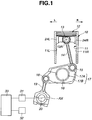
- FIG. 1 of the drawings there is schematically shown a multi link type piston-crank mechanism of an internal combustion engine, which an embodiment of the present invention.
- Fig. 1 denoted by numeral 10 is a cylinder block of an internal combustion engine to which the multi link type piston-crank mechanism of the invention is practically applied.
- cylinder block 10 has a plurality of cylinders 11 (only one is shown) each having a piston 12 slidably and reciprocatively received therein.
- Piston 12 has a piston pin 13 connected thereto.
- an axis of piston pin 13 is perpendicular to an axis of piston 12.
- the multi link type piston-crank mechanism of the invention comprises an upper link 14 that has an upper end pivotally connected to piston pin 13 of piston 12.
- a lower end of upper link 14 is pivotally connected through an upper pin 15 to a right upper end of a lower link 17 that is rotatably disposed on a crank pin 16 of a crankshaft of the engine.
- a left lower end of lower link 17 is pivotally connected through a control pin 18 to an upper end of a control link 19 that has a lower base part swingably held by a given portion of cylinder block 10.
- lower link 17 comprises two parts 17A and 17B that are detachably coupled. This detachably coupling is effective for easily mounting lower link 17 on crank pin 16.
- control link 19 As shown, the lower base part of control link 19 is swigably disposed on an eccentric cam portion 20 of a control shaft that is rotatably held by cylinder block 10.
- An axis "AX" of eccentric cam portion 20 is eccentric to an axis (not shown) of the control shaft, so that when the control shaft is rotated about its axis by an actuator 31 in accordance with an operation condition of the engine, an angular position of eccentric cam portion 20 (viz., the position of fulcrum of control link 19) is continuously changed. Due to this change, the movement of lower link 17 controlled by control link 19 is changed thereby to change positions of TDC and BDC of piston 12 changing a compression ratio of the engine (viz., engine compression ratio).
- control shaft and actuator 31 constitute a so-called variable compression ratio means that forces the above-mentioned multi link type piston-crank mechanism to work as a variable compression ratio mechanism.
- the engine compression ratio can be varied in accordance with an operation condition of the engine. Furthermore, the multi link type is superior to the single link type as to a freedom of setting piston stroke characteristic. Actually, by suitably setting a dimension of the links, it is possible to make the piston stroke characteristic close to the characteristic of a simple harmonic motion as compared with the single link type and at the same time it is possible to make an inclination angle of upper link 14 (viz., the angle relative to a traveling path of piston 12) in a piston move-down process smaller than that in a piston move-up process.
- a piston inertia force produced in the vicinity of TDC can be remarkably reduced, and a thrust load in thrust and counter thrust directions (viz., a thrust load applied from the cylinder to the piston) in the piston move-down process in the vicinity of TDC wherein a marked load is applied to the piston due to explosion can be reduced.
- the piston stroke characteristic being close to that of the simple harmonic motion, the dwell time of piston in the vicinity of BDC is shortened and thus acceleration of piston is increased while increasing the inertia force of piston.
- an after-mentioned time range in which an in-cylinder pressure (viz., the pressure in cylinder) is kept higher than the inertia force is reduced, so that the undesired contact of the piston with the lower edge of cylinder is avoided or at least minimized.
- the inclination angle of upper link 14 (viz., the angle relative to the traveling path of piston 12) is set smaller than a value set when the engine is set at a higher compression ratio.
- variable valve lift mechanism 32 that continuously varies the valve lift characteristic of each intake valve.
- the valve lift characteristic is represented by an operation angle and lift degree of the valve.
- the detail of such variable valve lift mechanism 32 is described in Japanese Laid-open Patent Application (Tokkai) 2003-232233 and thus description of the mechanism 32 will be omitted.
- Variable valve lift mechanism 32 and the above-mentioned actuator 31 are controlled by a control unit 33.
- control unit 33 By processing information signals issued from various sensors (not shown), control unit 33 computes an operation condition of the engine and issues appropriate instruction signals to mechanism 32 and actuator 31 in accordance with the engine operation condition computed.
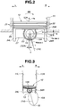
- Piston 12 is made of, for example, aluminum die-cast and as will be seen from Fig. 2 , has at a cylindrical crown portion thereof a plurality of ring grooves 21 (three in the illustrated example) that receive piston rings (not shown). Due to provision of such ring grooves 21, land portions 22 are left on the cylindrical crown portion of piston 12, as shown. That is, ring grooves 21 and land portions 22 are alternately provided on the crown portion of piston 12.
- Aligned piston pin bosses 23 are provided on a lower portion of piston 12 and have respective pin holes 23A with which a piston pin 13 is engaged.
- Each piston pin boss 23 is in the shape of a cylinder.
- a ring-shaped upper end of the above-mentioned upper link 14 is put between piston pin bosses 23 while pivotally receiving piston pin 13.
- axis 13A is an axis (or center axis) of piston pin 13.
- the axis 13A is a piston pin axis that passes through respective centers of piston pin bosses 23.
- two, viz., right and left skirt portions 24R and 24L project downward from diametrically opposed portions of the cylindrical crown portion of piston 12 respectively.
- an imaginary axis that passes through respective center points of the diametrically opposed portions of the cylindrical crown portion of piston 12 extends perpendicular to an after-mentioned piston axis 12A of piston 12.
- the direction in which the imaginary axis extends will be referred to as "thrust and counter thrust directions" hereinafter.
- apron portions 27 (viz., apron portions on this side and the other side) that are integral with the skirt portions 24R and 24L.
- the cylindrical crown portion, the right and left skirt portions 24R and 24L and the rounded apron portions constitute a cylindrically shaped body, that is, the piston 12.
- axis 12A designated by numeral 12A is an axis (or center axis) of piston 12, that is, an axis that passes through a center of the crown portion of piston 12.
- this axis 12A will be referred to as “piston axis" hereinafter.
- the above-mentioned piston pin axis 13A is offset by a distance of "Y" in the thrust and counter thrust directions with respect to the piston axis 12A.
- the side or direction (viz., right side in Figs. 1 to 6 ) toward which the piston pin axis 13A is offset or projects from the piston axis 12A will be called “pin offset side-R” or “pin offset direction-R”, and the other side or direction (viz., left side in Figs. 1 to 6 ) will be called “counter pin offset side-L” or “counter pin offset direction-L”.
- the locus or traveling path of upper pin 15 (viz., the piston stroke characteristic) is so set that throughout almost reciprocating movement of piston 12 that includes movement in the vicinity of BDC and TDC, upper pin 15 keeps the offset of "pin offset side-R".
- upper link 14 keeps an inclination state with its upper portion inclined toward "counter pin offset side-L”.
- the setting is so made that the inclination direction (viz., direction of inclination) of upper link 14 is reversed in the vicinity of TDC at a crank angle smaller than 40 degrees.
- the piston stroke characteristic is so made that when piston 12 comes to the position of BDC or near BDC, at least a part of the skirt portions 24R and 24L takes position below a lower edge 26 of cylinder 11. More specifically, as is seen from Fig. 2 , when piston 12 comes to BDC, the lower edge 26 of cylinder 11 positioned above the piston pin axis 13A. With such measure, undesired increase in height of cylinder 11, which would be caused an enlargement of the piston stroke, can be suppressed or at least minimized.
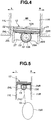
- piston 12 when the in-cylinder negative pressure is small and thus the downward inertial force is marked, piston 12 is pressed against the cylinder wall 11L of "counter pin offset side-L", and at the same time, due to the offset positioning of piston pin axis 13A, a turning moment in the "counter pin offset direction-L" (viz., in a counterclockwise direction in the drawing) is applied to piston 12, so that an upper portion of piston 12 at the "counter pin offset side-L" is strongly pressed against the cylinder wall 11L.
- piston 12 When the upward force due to the in-cylinder negative pressure is superior to the downward inertia force and thus the upward force becomes marked, piston 12 is pressed against the cylinder wall 11R of the "pin offset side-R" due to inclination of upper link 14, and at the same time, a turning moment "MR" in the direction of "pin offset side-MR” around the piston pin axis 13A (viz., in a clockwise direction in Figs. 2 and 4 ) due to the offset positioning of the piston pin axis 13A is applied to piston 12, so that as is exaggeratingly shown in Fig.
- piston 12 is forced to take such a posture as to receive a thrust load at an upper portion of piston 12, that is, the posture in which a lower portion of piston 12 is separated from cylinder 11, so that undesired contact between the skirt portion 24R (viz., the lower portion of piston 12) and the lower edge 26R of cylinder 11 is suppressed or at least minimized.
- variable valve lift mechanism 32 As is described hereinabove, ailments of piston 12, which would be caused by the in-cylinder negative pressure, are suppressed or at least minimized in the present invention. Thus, various restrictions that have been needed for eliminating the ailments are eased, and thus, the freedom of setting the variable valve lift mechanism 32 is high according to the present invention. That is, according to the present invention, it is possible to set an engine in a manner to produce a high in-cylinder negative pressure that is needed in a small lift condition, and thus, by suitably controlling the valve lift characteristic of the intake valves in accordance with an operation condition of the engine, fuel consumption and exhaust performance (viz., purification of exhaust gas) are improved.
- the multi link type piston-crank mechanism of internal combustion engine comprises an upper link that has an upper end pivotally connected to a piston of the engine through a piston pin, a lower link that is pivotally connected to a lower end of the upper link through an upper pin and rotatably mounted on a crank pin of a crankshaft of the engine, a control link that has one end swingably held by a cylinder block of the engine and the other end pivotally connected to the lower link through a control pin and an above-mentioned unique arrangement.
- the multi link type piston-crank mechanism of the present invention is able to exhibit a high freedom of setting piston stroke characteristic as compared with a single link type piston-crank mechanism.
- the multi link type piston-crank mechanism of the invention can be easily served as a variable compression ratio mechanism.
- arrangement of the links and the characteristic of the piston stroke are so made that when the piston takes BDC a part of the piston projects downward beyond the lower edge of the cylinder.
- increase in height of the cylinder which would be caused by increase of piston stroke, is suppressed or at least minimized. That is, compact construction of the engine is achieved.
- the piston pin axis is offset relative to the piston axis in the thrust and counter thrust directions, and when the piston comes to BDC, the offset direction of the piston pin axis relative to the piston axis in the thrust and counter thrust directions changes to a reversed offset direction. That is, in the vicinity of BDC of the piston in the move-down process, the upper link is forced to incline in the counter pin offset direction.
- the posture of the piston is so kept that the thrust load from the cylinder wall is always received by the upper portion of the piston. This means that undesired contact of the piston with the lower edge of the cylinder is suppressed or at least minimized.
- the upper portion of the piston by which the thrust load is received has a higher rigidity than the lower portion of the piston where skirt portions are formed. Thus, undesired deformation of such skirt portions is suppressed.
- the upper pin is offset relative to the piston pin axis in the same direction as the offset direction of the piston pin axis. That is, at such position of the piston, the upper link is inclined toward the counter pin offset direction.
- a marked downward combustion pressure is applied to the piston (viz., piston axis)
- the piston is pressed to the cylinder wall at the counter pin offset side due to the inclination of the upper link, and at the same time, a turning moment in the counter pin offset direction is applied to the piston due to the offset placement of the piston pin, so that an upper portion of the piston at the counter pin offset side is strongly pressed against the cylinder wall for receiving the thrust load. That is, for receiving the thrust load originating from the combustion pressure, the stronger upper portion of the piston is practically used.
- the respective lower ends of the piston have the same height in the thrust and counter thrust directions. However, if desired, the respective lower ends may have different heights.
Landscapes
- Engineering & Computer Science (AREA)
- Chemical & Material Sciences (AREA)
- Combustion & Propulsion (AREA)
- Mechanical Engineering (AREA)
- General Engineering & Computer Science (AREA)
- Output Control And Ontrol Of Special Type Engine (AREA)
- Pistons, Piston Rings, And Cylinders (AREA)
- Transmission Devices (AREA)
Claims (9)
- Mehrgliedriger Kolben-Kurbel-Mechanismus eines Verbrennungsmotors, umfassend:ein oberes Verbindungsglied (14), dessen eines Ende über einen Kolbenbolzen (13) schwenkbar mit einem Kolben (12) des Motors verbunden ist;ein unteres Verbindungsglied (17), das mit dem anderen Ende des oberen Verbindungsglieds (14) durch einen oberen Bolzen (15) schwenkbar verbunden ist und auf einem Kurbelzapfen (16) einer Kurbelwelle der Maschine drehbar angeordnet ist; undein Steuerglied (19), das einen Basisendabschnitt, der durch einen Körper des Motors schwenkbar gehalten ist, und ein vorderes Ende aufweist, das mit dem unteren Verbindungsglied (17) durch einen Steuerbolzen (18) schwenkbar verbunden ist, dadurch gekennzeichnet, dass:eine Achse (13A) des Kolbenbolzens (13) gegenüber einer Achse (12A) des Kolbens (12) in Schub- und Gegenschubrichtungen versetzt ist, undwenn der Kolben (12) den UT erreicht, ein Abschnitt des Kolbens (12) eine Position unterhalb eines unteren Rands (26) eines entsprechenden Zylinders (11) des Motors einnimmt, und der obere Bolzen (15) relativ zur Achse (13A) des Kolbenbolzens (13) in der gleichen Richtung wie eine Bolzenversatzrichtung versetzt ist, wobei die Achse (13A) des Kolbenbolzens (13) in der Schub- und Gegenschubrichtung relativ zu der Achse (12A) des Kolbens (12)) versetzt ist.
- Mehrgliedriger Kolben-Kurbel-Mechanismus nach Anspruch 1, wobei, wenn der Kolben (12) den OT erreicht, der obere Bolzen (15) relativ zur Achse (13A) des Kolbenbolzens (13) in die gleiche Richtung wie die Bolzenversatzrichtung versetzt ist.
- Mehrgliedriger Kolben-Kurbel-Mechanismus nach Anspruch 1 oder 2, wobei, wenn der Kolben den UT erreicht, die Achse (13A) des Kolbenbolzens (13) eine Position unterhalb des unteren Rands (26) des Zylinders einnimmt.
- Mehrgliedriger Kolben-Kurbel-Mechanismus nach Anspruch 3, wobei die folgende Ungleichung in dem Mechanismus erfüllt ist:
 Y: ein Versatzgrad der Achse (13A) des Kolbenbolzens (13) relativ zur Achse (12A) des Kolbens (12) in der Schub- und Gegenschubrichtung ist;X: ein Abstand von der Achse (13A) des Kolbenbolzens (13) zum unteren Rand (26) des Zylinders (11) in Richtung einer Achse des Zylinders (11) zum Zeitpunkt ist, wenn der Kolben (12) den UT einnimmt; undθ: ein Neigungswinkel des oberen Verbindungsglieds (14) relativ zur Achse des Zylinders (11) zum Zeitpunkt ist, wenn der Kolben (12) den UT einnimmt.
 - Mehrgliedriger Kolben-Kurbel-Mechanismus nach einem der Ansprüche 1 bis 4, ferner umfassend einen Mechanismus, mit dem eine Kolbenhubcharakteristik des Mechanismus der einer einfachen harmonischen Bewegung im Vergleich mit einem eingliedrigen Kolben-Kurbel-Mechanismus nahekommt, bei dem ein Kolben und ein entsprechender Kurbelzapfen durch eine einzige Pleuelstange verbunden sind.
- Mehrgliedriger Kolben-Kurbel-Mechanismus nach einem der Ansprüche 1 bis 5, ferner umfassend eine Betätigungsvorrichtung (31), mit der eine Position des Basisendabschnitts des Steuerglieds (19) zum Ändern des Hub des Kolbens (12) und somit zum Variieren eines Verdichtungsverhältnisses des Motors veränderbar ist.
- Mehrgliedriger Kolben-Kurbel-Mechanismus nach Anspruch 6, wobei, wenn ein niedriges Verdichtungsverhältnis durch die Betätigungsvorrichtung (31) eingestellt ist, die Position des UT des Kolbens im Vergleich zu der bei hohem Verdichtungsverhältnis festgelegten Position abgesenkt ist, und gleichzeitig ein Neigungswinkel des oberen Verbindungsglieds (14) relativ zu einer Achse des Zylinders (11) zum Zeitpunkt, wenn der Kolben (12) den UT einnimmt, reduziert ist.
- Mehrgliedriger Kolben-Kurbel-Mechanismus nach einem der Ansprüche 1 bis 7, ferner umfassend einen variablen Ventilmechanismus, mit dem eine Ventilhubcharakteristik von Motorventilen variierbar ist.
- Mehrgliedriger Kolben-Kurbel-Mechanismus eines BVerbrennungsmotors nach einem der Ansprüche 1 bis 8, umfassend:ein oberes Verbindungsglied (14), dessen eines Ende durch einen Kolbenbolzen (13) mit einem Kolben (12) des Motors schwenkbar verbunden ist;ein unteres Verbindungverbindungsglied (17), das mit dem anderen Ende des oberen Verbindungsglieds (14) durch einen oberen Bolzen (15) schwenkbar verbunden ist und auf einem Kurbelzapfen (16) einer Kurbelwelle der Maschine drehbar angeordnet ist;ein Steuerglied (19), das einen Basisendabschnitt, der durch einen Körper des Motors schwenkbar gehalten ist, und ein vorderes Ende aufweist, das mit dem unteren Verbindungsglied (17) durch einen Steuerbolzen (18) schwenkbar verbunden ist;eine Einrichtung zum Einrichten, dass eine Achse (13A) des Kolbenbolzens (13) relativ zu einer Achse (12A) des Kolbens (12) in Schub- und Gegenschubrichtungen versetzt ist; undeine Einrichtung zum Einrichten, dass, wenn der Kolben (12) den UT (d. h unteren Totpunkt) erreicht, ein Abschnitt des Kolbens (12) eine Position unterhalb eines unteren Rands (16) eines entsprechenden Zylinders (11) des Motors einnimmt, und der obere Bolzen (15) relativ zur Achse (13A) des Kolbens in die gleiche Richtung wie die Bolzenversatzrichtung versetzt ist, wobei die Achse (13A) des Kolbenbolzens (13) in der Schub- und Gegenschubrichtung relativ zur Achse (12A) des Kolbens (12) versetzt ist.
Applications Claiming Priority (1)
| Application Number | Priority Date | Filing Date | Title |
|---|---|---|---|
| JP2007202520A JP4816588B2 (ja) | 2007-08-03 | 2007-08-03 | 内燃機関の複リンク式ピストン−クランク機構 |
Publications (3)
| Publication Number | Publication Date |
|---|---|
| EP2020491A2 EP2020491A2 (de) | 2009-02-04 |
| EP2020491A3 EP2020491A3 (de) | 2014-12-03 |
| EP2020491B1 true EP2020491B1 (de) | 2018-09-12 |
Family
ID=39926564
Family Applications (1)
| Application Number | Title | Priority Date | Filing Date |
|---|---|---|---|
| EP08011433.3A Ceased EP2020491B1 (de) | 2007-08-03 | 2008-06-24 | Kurbelmechanismus mit mehreren Verbindungen eines Verbrennungsmotors |
Country Status (3)
| Country | Link |
|---|---|
| US (1) | US8011343B2 (de) |
| EP (1) | EP2020491B1 (de) |
| JP (1) | JP4816588B2 (de) |
Families Citing this family (3)
| Publication number | Priority date | Publication date | Assignee | Title |
|---|---|---|---|---|
| JP5949148B2 (ja) * | 2012-05-23 | 2016-07-06 | 日産自動車株式会社 | 複リンク式内燃機関 |
| US9790853B2 (en) | 2013-05-20 | 2017-10-17 | Thomas Steve HUMPHRIES | Variable geometry power transfer for fluid flow machines |
| DE102015122029A1 (de) | 2015-12-16 | 2017-06-22 | Andre Lohre | Bildschirm für Navigationssysteme |
Family Cites Families (11)
| Publication number | Priority date | Publication date | Assignee | Title |
|---|---|---|---|---|
| JPS58144044U (ja) * | 1982-03-23 | 1983-09-28 | 日産ディーゼル工業株式会社 | 内燃機関のピストン |
| JPS592967U (ja) * | 1982-06-30 | 1984-01-10 | 日産ディーゼル工業株式会社 | 内燃機関のピストン |
| JPS60162227U (ja) * | 1984-04-06 | 1985-10-28 | スズキ株式会社 | エンジン |
| JPH09242605A (ja) * | 1996-02-29 | 1997-09-16 | Unisia Jecs Corp | 内燃機関用ピストン |
| JP3911977B2 (ja) * | 2000-08-17 | 2007-05-09 | 日産自動車株式会社 | 内燃機関の複リンク機構 |
| JP3952680B2 (ja) * | 2000-10-03 | 2007-08-01 | 日産自動車株式会社 | 可変圧縮比機構を備えた内燃機関 |
| JP4411779B2 (ja) * | 2000-12-06 | 2010-02-10 | 日産自動車株式会社 | レシプロ式内燃機関のクランク機構 |
| JP2003232233A (ja) | 2001-12-06 | 2003-08-22 | Nissan Motor Co Ltd | 内燃機関の制御装置 |
| JP2004162895A (ja) | 2002-09-19 | 2004-06-10 | Nissan Motor Co Ltd | 内燃機関のリンク機構 |
| JP2007202520A (ja) | 2006-02-03 | 2007-08-16 | Oriental Yeast Co Ltd | 水羊羹風フィリング |
| JP4760453B2 (ja) * | 2006-03-06 | 2011-08-31 | 日産自動車株式会社 | レシプロ式エンジン |
-
2007
- 2007-08-03 JP JP2007202520A patent/JP4816588B2/ja not_active Expired - Fee Related
-
2008
- 2008-06-24 EP EP08011433.3A patent/EP2020491B1/de not_active Ceased
- 2008-07-31 US US12/183,583 patent/US8011343B2/en not_active Expired - Fee Related
Non-Patent Citations (1)
| Title |
|---|
| None * |
Also Published As
| Publication number | Publication date |
|---|---|
| US8011343B2 (en) | 2011-09-06 |
| EP2020491A3 (de) | 2014-12-03 |
| JP4816588B2 (ja) | 2011-11-16 |
| EP2020491A2 (de) | 2009-02-04 |
| JP2009036148A (ja) | 2009-02-19 |
| US20090031994A1 (en) | 2009-02-05 |
Similar Documents
| Publication | Publication Date | Title |
|---|---|---|
| US6390035B2 (en) | Reciprocating internal combustion engine | |
| US6546900B2 (en) | Variable compression ratio mechanism for reciprocating internal combustion engine | |
| EP1950390B1 (de) | Motor mit variablen hubeigenschaften | |
| EP1533495B1 (de) | Brennkraftmaschine | |
| US7228838B2 (en) | Internal combustion engine | |
| JP2009036128A (ja) | 複リンク式可変圧縮比エンジン | |
| US6615773B2 (en) | Piston control mechanism of reciprocating internal combustion engine of variable compression ratio type | |
| EP2020491B1 (de) | Kurbelmechanismus mit mehreren Verbindungen eines Verbrennungsmotors | |
| WO2009118614A1 (en) | Internal combustion engine | |
| JP4816587B2 (ja) | 内燃機関の複リンク式ピストン−クランク機構 | |
| JP4271138B2 (ja) | エンジンの振動除去装置 | |
| JP4581675B2 (ja) | 内燃機関 | |
| US10208662B2 (en) | Internal combustion engine | |
| JP2005180302A (ja) | 内燃機関のピストン駆動装置 | |
| JP2026066002A (ja) | ピストン、内燃機関、及び、車両 | |
| JP2018112129A (ja) | 可変圧縮比機構 | |
| JP2008115828A (ja) | レシプロ式内燃機関 | |
| JP2018115647A (ja) | ピストン上、下死点及び圧縮比リミッタ付二分割コンロッドl形ヨーク式行程容積連続可変装置 | |
| JP2005003093A (ja) | 複リンク式コンロッド機構を有する内燃機関 | |
| JP2009036143A (ja) | 内燃機関 | |
| JP2008069679A (ja) | ストローク特性可変エンジン | |
| JP2019167945A (ja) | 三分割コンロッド式行程容積、圧縮比連続可変装置 | |
| JP2017223210A (ja) | 二分割コンロッドl形ヨーク対向ピストン型行程容積連続可変装置 | |
| JP2010185294A (ja) | V型多気筒エンジン |
Legal Events
| Date | Code | Title | Description |
|---|---|---|---|
| PUAI | Public reference made under article 153(3) epc to a published international application that has entered the european phase |
Free format text: ORIGINAL CODE: 0009012 |
|
| 17P | Request for examination filed |
Effective date: 20080624 |
|
| AK | Designated contracting states |
Kind code of ref document: A2 Designated state(s): AT BE BG CH CY CZ DE DK EE ES FI FR GB GR HR HU IE IS IT LI LT LU LV MC MT NL NO PL PT RO SE SI SK TR |
|
| AX | Request for extension of the european patent |
Extension state: AL BA MK RS |
|
| PUAL | Search report despatched |
Free format text: ORIGINAL CODE: 0009013 |
|
| AK | Designated contracting states |
Kind code of ref document: A3 Designated state(s): AT BE BG CH CY CZ DE DK EE ES FI FR GB GR HR HU IE IS IT LI LT LU LV MC MT NL NO PL PT RO SE SI SK TR |
|
| AX | Request for extension of the european patent |
Extension state: AL BA MK RS |
|
| RIC1 | Information provided on ipc code assigned before grant |
Ipc: F02B 75/04 20060101AFI20141024BHEP |
|
| AKX | Designation fees paid |
Designated state(s): DE FR GB |
|
| AXX | Extension fees paid |
Extension state: AL Extension state: RS Extension state: MK Extension state: BA |
|
| GRAP | Despatch of communication of intention to grant a patent |
Free format text: ORIGINAL CODE: EPIDOSNIGR1 |
|
| INTG | Intention to grant announced |
Effective date: 20180614 |
|
| GRAS | Grant fee paid |
Free format text: ORIGINAL CODE: EPIDOSNIGR3 |
|
| GRAA | (expected) grant |
Free format text: ORIGINAL CODE: 0009210 |
|
| AK | Designated contracting states |
Kind code of ref document: B1 Designated state(s): DE FR GB |
|
| REG | Reference to a national code |
Ref country code: GB Ref legal event code: FG4D |
|
| REG | Reference to a national code |
Ref country code: DE Ref legal event code: R096 Ref document number: 602008056900 Country of ref document: DE |
|
| REG | Reference to a national code |
Ref country code: DE Ref legal event code: R097 Ref document number: 602008056900 Country of ref document: DE |
|
| PLBE | No opposition filed within time limit |
Free format text: ORIGINAL CODE: 0009261 |
|
| STAA | Information on the status of an ep patent application or granted ep patent |
Free format text: STATUS: NO OPPOSITION FILED WITHIN TIME LIMIT |
|
| 26N | No opposition filed |
Effective date: 20190613 |
|
| PGFP | Annual fee paid to national office [announced via postgrant information from national office to epo] |
Ref country code: GB Payment date: 20220506 Year of fee payment: 15 Ref country code: FR Payment date: 20220510 Year of fee payment: 15 Ref country code: DE Payment date: 20220505 Year of fee payment: 15 |
|
| REG | Reference to a national code |
Ref country code: DE Ref legal event code: R119 Ref document number: 602008056900 Country of ref document: DE |
|
| GBPC | Gb: european patent ceased through non-payment of renewal fee |
Effective date: 20230624 |
|
| PG25 | Lapsed in a contracting state [announced via postgrant information from national office to epo] |
Ref country code: DE Free format text: LAPSE BECAUSE OF NON-PAYMENT OF DUE FEES Effective date: 20240103 Ref country code: GB Free format text: LAPSE BECAUSE OF NON-PAYMENT OF DUE FEES Effective date: 20230624 |
|
| PG25 | Lapsed in a contracting state [announced via postgrant information from national office to epo] |
Ref country code: FR Free format text: LAPSE BECAUSE OF NON-PAYMENT OF DUE FEES Effective date: 20230630 |