EP2020330A2 - Verfahren und Vorrichtung zur Vorgabe einer Ausgangsgröße einer Antriebseinheit - Google Patents
Verfahren und Vorrichtung zur Vorgabe einer Ausgangsgröße einer Antriebseinheit Download PDFInfo
- Publication number
- EP2020330A2 EP2020330A2 EP08104908A EP08104908A EP2020330A2 EP 2020330 A2 EP2020330 A2 EP 2020330A2 EP 08104908 A EP08104908 A EP 08104908A EP 08104908 A EP08104908 A EP 08104908A EP 2020330 A2 EP2020330 A2 EP 2020330A2
- Authority
- EP
- European Patent Office
- Prior art keywords
- detected
- setpoint
- error
- case
- unit
- Prior art date
- Legal status (The legal status is an assumption and is not a legal conclusion. Google has not performed a legal analysis and makes no representation as to the accuracy of the status listed.)
- Granted
Links
- 238000000034 method Methods 0.000 title claims abstract description 18
- 238000001514 detection method Methods 0.000 claims description 36
- 230000008859 change Effects 0.000 claims description 23
- 238000006243 chemical reaction Methods 0.000 claims description 4
- 238000002485 combustion reaction Methods 0.000 abstract description 4
- 230000004044 response Effects 0.000 abstract description 2
- 230000007935 neutral effect Effects 0.000 description 14
- 230000009849 deactivation Effects 0.000 description 5
- 230000008901 benefit Effects 0.000 description 4
- 238000005070 sampling Methods 0.000 description 4
- 230000004913 activation Effects 0.000 description 2
- 230000002123 temporal effect Effects 0.000 description 2
- 230000009471 action Effects 0.000 description 1
- 230000001419 dependent effect Effects 0.000 description 1
- 238000010586 diagram Methods 0.000 description 1
- 230000006870 function Effects 0.000 description 1
- 230000007257 malfunction Effects 0.000 description 1
- 230000002688 persistence Effects 0.000 description 1
- 230000009467 reduction Effects 0.000 description 1
- 230000001105 regulatory effect Effects 0.000 description 1
- 230000001960 triggered effect Effects 0.000 description 1
Images
Classifications
-
- G—PHYSICS
- G05—CONTROLLING; REGULATING
- G05B—CONTROL OR REGULATING SYSTEMS IN GENERAL; FUNCTIONAL ELEMENTS OF SUCH SYSTEMS; MONITORING OR TESTING ARRANGEMENTS FOR SUCH SYSTEMS OR ELEMENTS
- G05B23/00—Testing or monitoring of control systems or parts thereof
- G05B23/02—Electric testing or monitoring
- G05B23/0205—Electric testing or monitoring by means of a monitoring system capable of detecting and responding to faults
- G05B23/0259—Electric testing or monitoring by means of a monitoring system capable of detecting and responding to faults characterized by the response to fault detection
- G05B23/0262—Confirmation of fault detection, e.g. extra checks to confirm that a failure has indeed occurred
-
- B—PERFORMING OPERATIONS; TRANSPORTING
- B60—VEHICLES IN GENERAL
- B60K—ARRANGEMENT OR MOUNTING OF PROPULSION UNITS OR OF TRANSMISSIONS IN VEHICLES; ARRANGEMENT OR MOUNTING OF PLURAL DIVERSE PRIME-MOVERS IN VEHICLES; AUXILIARY DRIVES FOR VEHICLES; INSTRUMENTATION OR DASHBOARDS FOR VEHICLES; ARRANGEMENTS IN CONNECTION WITH COOLING, AIR INTAKE, GAS EXHAUST OR FUEL SUPPLY OF PROPULSION UNITS IN VEHICLES
- B60K31/00—Vehicle fittings, acting on a single sub-unit only, for automatically controlling vehicle speed, i.e. preventing speed from exceeding an arbitrarily established velocity or maintaining speed at a particular velocity, as selected by the vehicle operator
- B60K31/16—Vehicle fittings, acting on a single sub-unit only, for automatically controlling vehicle speed, i.e. preventing speed from exceeding an arbitrarily established velocity or maintaining speed at a particular velocity, as selected by the vehicle operator having means to prevent or discourage unauthorised use or adjusting of the controlling means
Definitions
- the invention is based on a method and a device for specifying an output variable of a drive unit according to the preamble of the independent claims.
- the inventive method and the inventive device for specifying an output variable of a drive unit with the features of the independent claims have the advantage that is checked at a specification of the target value of the output, whether it is based on an actuation of the control element and that if it is determined that this is not the case, an error is detected.
- an erroneous specification of the desired value of the output variable can be detected in a simple manner.
- the erroneous specification of the setpoint of the output variable is thus automatically detected. This also allows automatic execution of an error response action on a detected error.
- the error is detected only when no operation of the control element has been detected or when the detection of the operation of the control element is more than a predetermined threshold before the first detection of the specification of the setpoint.
- a predetermined threshold before the first detection of the specification of the setpoint.
- a further advantage results from the fact that, in the case in which no error was detected due to the operation of the operating element detected before the initial detection of the setpoint value, the specification of the setpoint value is compared with a last-specified desired value to a change and that for the case in which a change is detected, which is not due to the detected type of operation of the operating element, yet an error is detected.
- the specification of the setpoint value is compared with a last-specified desired value to a change and that for the case in which a change is detected, which is not due to the detected type of operation of the operating element, yet an error is detected.
- a further advantage is obtained if, in the case in which the specification of the setpoint value is increased compared to the last-specified setpoint value, an error is detected if an actuation of the control element for lowering the setpoint value or for resuming the last predefined setpoint value has been detected. This represents a simple realization of the error detection for a faulty increased setpoint.
- the specification of the setpoint value is compared with a last-specified desired value to a change and that in the event in which no change is detected, although a type of operation of the control element has been detected, which causes a change in the setpoint, yet an error is detected.
- a faulty persistence of the setpoint on the last preset setpoint can be detected in a simple manner.
- a speed or a speed as an output variable.
- the method according to the invention and the device according to the invention can be used, for example, in a cruise control or in a speed control.
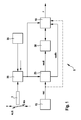
- FIG. 1 5 indicates a device for presetting an output variable of a drive unit.
- the drive unit may comprise, for example, an internal combustion engine or an electric motor or a hybrid drive of the internal combustion engine and the electric motor and, for example, drive a vehicle.
- the internal combustion engine may be, for example, a diesel engine or a gasoline engine.
- the device 5 can be implemented, for example, in software and / or hardware in a motor control of the drive unit.
- the output quantity may be, for example, a torque, a power, a speed or a rotational speed.
- the drive unit drives a vehicle and that the output variable of the drive unit is the speed of the vehicle.
- the device 5 in this case comprises a default unit 25, at the output of which the target speed vsoll is output.
- the target speed vsoll can be used, for example, and in an in FIG. 1 not shown, are supplied to a vehicle speed control.
- the device 5 further comprises a memory unit 30, the memory contents of which are overwritten by the respectively current desired speed value vsoll.
- the device 5 further comprises a detection unit 20 to which the signal of a control element 1 is supplied.
- the control element 1 may be, for example, a steering column lever of a Tempomats act. This is movable in four directions, as in FIG. 1 is shown.
- a predetermined target speed vsoll be increased by a predetermined increment, for example, 1 kilometer per hour. If no setpoint speed vsoll is currently set, the current actual speed vist of the vehicle is to be set as desired speed vsoll by moving the steering column lever 1 into the "plus position".
- a predetermined target speed vsoll By moving the steering column lever 1 down into the "minus position” is a predetermined target speed vsoll by a predetermined decrement, for example, 1 kilometer per hour, to be lowered.
- a predetermined target speed vsoll By moving the steering column lever 1 forward in the "WA" position is in the event that no target speed vsoll currently specified, the last specified target speed vsoll be specified again. This is also called resumption.
- the detection unit 20 detects the position of the steering column lever 1 and forwards the detected position both to the default unit 25 and to a test unit 10.
- the default unit 25 is also supplied by a detection unit 15, for example a speed sensor, the actual speed vist of the vehicle.
- the detection unit 15 can optionally be arranged outside the device 5.
- the steering column lever 1 may optionally be arranged outside the device 5.
- the detection unit 20, the default unit 25, the memory unit 30 and the test unit 10 are components of the device 5.
- the last used target speed vsoll is stored. If the default unit 25 is deactivated and receives the position "WA" from the detection unit 20 as the current setting of the steering column lever 1, then the default unit 25 is activated and outputs the last-used value for the setpoint speed as desired speed. If, however, the default unit 25 is activated and receives the position "OFF" from the detection unit 20 as the current position of the steering column lever 1, the default unit 25 becomes Deactivates and stores the value for the setpoint speed previously output as the last used setpoint speed. If the default unit 25 is deactivated and receives the position "plus” of the steering column lever 1 from the detection unit, then the default unit 25 is activated and outputs the current actual speed vist as desired speed vsoll.
- the default unit 25 is activated and receives the position "plus” of the steering column lever 1 from the detection unit 20, then the target speed v.sub.set output by it is increased by the increment described. If, on the other hand, the default unit 25 is activated and receives from the detection unit 20 the position "minus" of the pitman arm 1, it lowers the output target speed vsoll by the decrement described above.
- the activation of the default unit 25 is synonymous with the activation of the vehicle speed control and the deactivation of the default unit 25 is equivalent to the deactivation of the vehicle speed control.
- the test unit 10 samples the contents of the memory unit 30, for example, in a predetermined sampling time frame. Furthermore, the test unit 10 is supplied by the default unit 25 with the stored last used value for the desired speed vsollz.
- the last used value vsollz for the setpoint speed is, when the default unit 25 is activated, the setpoint speed value last output by the default unit 25 before a change to the current setpoint speed value vsoll.
- the last used value vsollz is the target speed of the target speed value used in the last activated operation of the default unit 25.
- the default unit 25 In the event that the default unit 25 is deactivated, it outputs in its output a neutral value, with which the memory unit 30 is also overwritten and based on which it is clearly recognizable that the default unit 25 is deactivated.
- the test unit 10 now checks whether the scanned content of the memory unit 30 is not equal to the neutral value, that is, the default unit 25 is activated. If this is the case, then the test unit 10 compares the current setpoint speed vsoll of the memory unit 30 with the last used setpoint speed vsollz. provides the test unit 10 detects a change, it concludes that an operation of the pitman arm 1 must have been present, which led to this change. On the basis of the output signal of the detection unit 20, the test unit 10 checks whether such actuation of the steering column lever 1 has been detected. If this is not the case, an error signal is set at the output of the test unit 10.
- the test unit 10 detects actuation of the steering column lever 1 at a time which is less than a predefined threshold value before the first detection of a change in the setpoint speed output by the predetermining unit 25, then a reset error signal F is output at the output of the test unit 10 that no error is detected. Otherwise, that is, when detected operation of the steering column lever 1 is longer than the predetermined threshold value compared to the time of the first detected change in the target speed output by the default unit 25, the test unit 10 detects an error and the output signal F of the test unit 10 is set.
- the threshold for the time for example, on a test bed, for example, be applied so suitable that he is not greater than the maximum detected delay between an actuation of the pitman arm 1 and the consequent change in the content of the storage unit 30 is. In this way, a reliable error detection can be realized.
- a threshold for example, a value of one second was found to be suitable.
- An error detection by the test unit 10 is optionally also possible for the case in which the time interval between an actuation of the steering column lever 1 in the "plus” position, in the "minus” position or in the "WA” position and a subsequent change of the content of the memory unit 30 is less than is the predetermined threshold.
- the check unit 10 checks whether the change in the content of the storage unit 30 correlates with the selected position in the operation of the pitman arm 1. If the test unit 10 detects an increase in the memory contents of the memory unit 30 during a preceding actuation of the pitman arm 1 in the "minus" position or in the "WA” position, an error is detected and the error signal F is set.
- test unit 10 detects a decrease in the memory contents of the memory unit 30 by more than a decrement in a preceding actuation of the pitman arm 1 in the "minus” position, an error is also detected and the error signal F is set. If the test unit 10 detects a decrease in the memory contents of the memory unit 30 in advance of the operation of the pitman arm 1 in the "plus” position or in the "WA” position, an error is detected and the error signal F is set. If the test unit 10 detects an increase by more than one increment after the preceding operation of the steering column lever 1 in the "plus” position, an error is detected and the error signal F is set.
- test unit 10 detects a deviation between vsoll and vsollz after previous actuation of the steering column lever 1 in the "WA" position, an error is also detected and the error signal F is set. It is assumed that after an actuation of the steering column lever 1 in the "OFF" position, the value vsollz in the default unit 25 is not set to the neutral value, but remains at the last set value for the target speed. Only the target speed vsoll output by the predefined unit 25 to the memory unit 30 is set to the neutral value in this case.
- test unit 10 sets a target speed vsoll not equal to the neutral value in the memory unit 30 after the preceding operation of the pitman arm 1 in the "OFF" position, an error is detected and the error signal F is set.
- test unit 10 detects a change in the memory contents of the memory unit 30 from the neutral value to a value different from the actual speed for the target speed vsoll after the preceding operation of the steering column lever 1 in the "plus” position, an error is also detected and the error signal F set.
- the output of the detection unit 15 also supplied to the test unit 10, as in FIG. 1 is shown in dashed lines. If the test unit 10, upon a change in the memory contents of the memory unit 30 from the neutral value to a value other than the neutral value for the target speed vsoll, determines that an actuation of the pitman arm 1 precedes the "minus" position, it detects an error and the error signal F is set.
- a neutral value for example, the value zero can be used.
- an error counter can be incremented, wherein an error is only detected when the error counter reading reaches or exceeds a predetermined threshold value.
- an error reaction measure can be initiated, for example a deactivation of the vehicle speed control or a limitation of the output torque of the drive unit, for example as a function of the extent to which the target speed vsoll is exceeded by the actual speed vist.
- the drive unit can also be completely switched off.
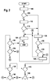
- FIG. 2 a flow chart for an exemplary sequence of the method according to the invention is shown.
- the test unit 10 samples the memory unit 30 at a program point 100 at a predetermined sampling time, for example in a predetermined sampling time interval.
- the schedule can after FIG. 2 for each of these sampling times.
- a branch is made to a program point 105.
- the test unit checks whether the target value vsoll read from the memory unit 30 at program point 100 is not equal to the previous target value vsollz. If this is the case, a branch is made to a program point 120, otherwise a branch is made to a program point 125.
- test unit 10 checks on the basis of the recorded output signal of the detection unit 20 when most recently an actuation of the Steering column lever 1 has taken place. Subsequently, a branch is made to a program point 115.
- the test unit 10 checks whether the last actuation of the steering column lever 1 lags in time by more than the predetermined threshold. If this is the case, a branch is made to a program point 120, otherwise a branch is made to a program point 125.
- the error signal F is set at the output of the test unit 10. Afterwards the program is left.
- test unit 10 checks on the basis of the recorded signal received by the detection unit 20, which type was the last operation of the steering column lever 1. Subsequently, a branch is made to a program point 130.
- the test unit 10 checks whether the last actuation of the steering column lever 1 was an actuation in the "WA" position. If this is the case, the program branches to a program point 135, otherwise a branch is made to a program point 145.
- test unit 10 checks whether the currently sampled value of the memory contents of the memory unit 30 is different from the value vsollz. If this is the case, the program branches to program point 120, otherwise it becomes a program point 140.
- a reset error signal F is output from the test unit 10. Afterwards the program is left.
- the test unit 10 checks whether the last operation of the steering column lever 1 was an operation in the "plus" position. If this is the case, the program branches to a program point 150, otherwise a branch is made to a program point 155.
- the test unit 10 checks whether the memory content of the memory unit 30 is greater than the value vsollz by one increment or whether the memory content of the memory unit 30 has been changed from the neutral value to the actual speed vist. If this is the case, the program branches to program point 140, otherwise the program branches to program point 120.
- At program point 155 checks the test unit 10 based on the recorded history of the output signal of the detection unit 20, whether the last operation of the pitman arm 1 was an operation in the "minus" position. If this is the case, the program branches to a program point 160, otherwise a branch is made to a program point 165.
- test unit 10 checks whether the memory content of the memory unit 30 is reduced by a decrement from the value vsollz or whether the memory content of the memory unit 30 corresponds to the neutral value. If this is the case, program item 140 is entered, otherwise the program branches to program item 120.
- test unit 10 checks whether the last operation of the pitman arm 1 was an operation in the "OFF" position. If this is the case, a branch is made to a program point 170, otherwise the program is left.
- test unit 10 checks whether the memory content of the memory unit 30 corresponds to the neutral value. If this is the case, the program branches to program point 140, otherwise the program branches to program point 120.
- the output size of the drive unit may alternatively be a speed of the drive unit as well as the speed.
- a setpoint speed with the aid of a corresponding control element 1 are predetermined in the same manner as the desired speed described above and set in the context of a speed control.
- FIG. 1 a vehicle brake 35 shown, which also does not have to belong to the device 5 and upon actuation of which a corresponding actuation signal is transmitted to the detection unit 20.
- An actuation of the vehicle brake 35 is interpreted by the detection unit 20 in the same manner as the operation of the steering column lever 1 in the "OFF" position and has a deactivation of the vehicle speed controller and the default unit 25 in error-free operation.
- the test unit 10 can not distinguish in such a deactivation, whether it is due to actuation of the steering column lever 1 in the "OFF" position or by actuation of the vehicle brake 35.
- the operation of the steering column lever 1 in the "OFF" position is indistinguishable from the operation of the vehicle brake 35, so that the operation of the vehicle brake 35 in the same way affects the fault detection described, as the operation of the pitman arm 1 in the "off" position.
- the target speed vsoll is set to the neutral value, which is also considered in the present invention as a specification of the target value of the output, here the vehicle speed.
Landscapes
- Engineering & Computer Science (AREA)
- Transportation (AREA)
- General Physics & Mathematics (AREA)
- Automation & Control Theory (AREA)
- Chemical & Material Sciences (AREA)
- Combustion & Propulsion (AREA)
- Physics & Mathematics (AREA)
- Mechanical Engineering (AREA)
- Control Of Transmission Device (AREA)
- Steering Control In Accordance With Driving Conditions (AREA)
- Electric Propulsion And Braking For Vehicles (AREA)
- Control Of Vehicle Engines Or Engines For Specific Uses (AREA)
- Control Of Electric Motors In General (AREA)
- Controls For Constant Speed Travelling (AREA)
Abstract
Description
- Die Erfindung geht von einem Verfahren und von einer Vorrichtung zur Vorgabe einer Ausgangsgröße einer Antriebseinheit nach der Gattung der unabhängigen Ansprüche aus.
- Aus der
DE 101 62 017 A1 ist bereits eine Vorrichtung und ein Verfahren zur Regelung der Fahrgeschwindigkeit eines Fahrzeugs bekannt, bei denen mittels Betätigung eines Bedienelementes eine Sollgeschwindigkeit des Fahrzeugs vorgegeben wird. - Das erfindungsgemäße Verfahren und die erfindungsgemäße Vorrichtung zur Vorgabe einer Ausgangsgröße einer Antriebseinheit mit den Merkmalen der unabhängigen Ansprüche haben demgegenüber den Vorteil, dass bei einer Vorgabe des Sollwertes der Ausgangsgröße geprüft wird, ob diese auf einer Betätigung des Bedienelementes beruht und dass wenn festgestellt wird, dass dies nicht der Fall ist, ein Fehler erkannt wird. Auf diese Weise lässt sich eine fehlerhafte Vorgabe des Sollwertes der Ausgangsgröße auf einfache Weise detektieren. Die fehlerhafte Vorgabe des Sollwertes der Ausgangsgröße wird somit automatisch detektiert. Dies ermöglicht auch eine automatische Durchführung einer Fehlerreaktionsmaßnahme auf einen erkannten Fehler hin.
- Durch die in den Unteransprüchen aufgeführten Maßnahmen sind vorteilhafte Weiterbildungen und Verbesserungen des im Hauptanspruch angegebenen Verfahrens möglich.
- Vorteilhaft ist es, dass geprüft wird, ob eine Vorgabe des Sollwertes vorliegt, dass für den Fall, in dem die Prüfung ergibt, dass eine Vorgabe des Sollwertes vorliegt, geprüft wird, ob zeitlich vor der erstmaligen Detektion der Vorgabe des Sollwertes das Bedienelement betätigt wurde und dass wenn dies nicht der Fall ist, ein Fehler erkannt wird. Auf diese Weise lässt sich die Fehlererkennung besonders einfach durch den im fehlerfreien Fall vorhandenen zeitlichen Zusammenhang zwischen der Betätigung des Bedienelementes zur Vorgabe des Sollwertes und der dadurch bedingten tatsächlichen Vorgabe des Sollwertes aufbauen.
- Dabei ist es besonders vorteilhaft, dass der Fehler nur dann erkannt wird, wenn keine Betätigung des Bedienelementes detektiert wurde oder wenn die Detektion der Bedienung des Bedienelementes zeitlich um mehr als ein vorgegebener Schwellwert vor der erstmaligen Detektion der Vorgabe des Sollwertes liegt. Auf diese Weise lässt sich der zeitliche Zusammenhang zwischen der Betätigung des Bedienelementes zur Vorgabe des Sollwertes und der tatsächlichen Vorgabe des Sollwertes durch den vorgegebenen Schwellwert eindeutig abbilden und auf diese Weise die Zuverlässigkeit der Fehlererkennung erhöhen.
- Ein weiterer Vorteil ergibt sich, dass für den Fall, in dem aufgrund der zeitlich vor der erstmaligen Detektion der Vorgabe des Sollwertes detektierten Betätigung des Bedienelementes kein Fehler erkannt wurde, die Vorgabe des Sollwertes mit einem zuletzt vorgegebenen Sollwert auf eine Änderung verglichen wird und dass für den Fall, in dem eine Änderung erkannt wird, die nicht auf die detektierte Art der Betätigung des Bedienelementes zurückzuführen ist, dennoch ein Fehler erkannt wird. Auf diese Weise lässt sich auch eine fehlerhafte Vorgabe des Sollwertes aufgrund der Betätigung des Bedienelementes in einfacher Weise erkennen. Somit wird eine differenziertere Fehlererkennung ermöglicht.
- Ein weiterer Vorteil ergibt sich, wenn für den Fall, in dem die Vorgabe des Sollwertes gegenüber dem zuletzt vorgegebenen Sollwert erhöht ist, ein Fehler erkannt wird, wenn eine Betätigung des Bedienelementes zur Absenkung des Sollwertes oder zur Wiederaufnahme des zuletzt vorgegebenen Sollwertes detektiert wurde. Dies stellt eine einfache Realisierung der Fehlererkennung für einen fehlerhaft erhöhten Sollwert dar.
- Vorteilhaft ist auch, dass für den Fall, in dem die Vorgabe des Sollwertes gegenüber dem zuletzt vorgegebenen Sollwert erniedrigt ist, ein Fehler erkannt wird, wenn eine Betätigung des Bedienelementes zur Erhöhung des Sollwertes oder zur Wiederaufnahme des zuletzt vorgegebenen Sollwertes detektiert wurde. Auf diese Weise lässt sich besonders einfach eine fehlerhafte Erniedrigung des Sollwertes aufgrund der Betätigung des Bedienelementes detektieren.
- Vorteilhaft ist, dass für den Fall, in dem aufgrund der zeitlich vor der erstmaligen Detektion der Vorgabe des Sollwertes detektierten Betätigung des Bedienelementes kein Fehler erkannt wurde, die Vorgabe des Sollwertes mit einem zuletzt vorgegebenen Sollwert auf eine Änderung verglichen wird und dass für den Fall, in dem keine Änderung erkannt wird, obwohl eine Art der Betätigung des Bedienelementes detektiert wurde, die eine Veränderung des Sollwertes bedingt, dennoch ein Fehler erkannt wird. Auf diese Weise lässt sich ein fehlerhaftes Verharren des Sollwertes auf dem zuletzt vorgegebenen Sollwert in einfacher Weise erkennen.
- Vorteilhaft ist weiterhin, wenn bei erkanntem Fehler eine Fehlerreaktionsmaßnahme eingeleitet wird. Auf diese Weise kann ein unerwünschter Fehlbetrieb der Antriebseinheit verhindert werden.
- Besonders vorteilhaft ist die Verwendung einer Geschwindigkeit oder einer Drehzahl als Ausgangsgröße. Auf diese Weise lässt sich das erfindungsgemäße Verfahren und die erfindungsgemäße Vorrichtung beispielsweise bei einer Geschwindigkeitsregelung oder bei einer Drehzahlregelung einsetzen.
- Ein Ausführungsbeispiel der Erfindung ist in der Zeichnung dargestellt und in der nachfolgenden Beschreibung näher erläutert. Es zeigen:
- Figur 1
- ein Funktionsdiagramm zur Erläuterung der erfindungsgemäßen Vorrichtung und
- Figur 2
- einen Ablaufplan für einen beispielhaften Ablauf des erfindungs- gemäßen Verfahrens.
- In
Figur 1 kennzeichnet 5 eine Vorrichtung zur Vorgabe einer Ausgangsgröße einer Antriebseinheit. Die Antriebseinheit kann beispielsweise eine Brennkraftmaschine oder einen Elektromotor oder einen Hybridantrieb aus Brennkraftmaschine und Elektromotor umfassen und beispielsweise ein Fahrzeug antreiben. Bei der Brennkraftmaschine kann es sich beispielsweise um einen Dieselmotor oder um einen Ottomotor handeln. Die Vorrichtung 5 kann beispielsweise software-und/oder hardwaremäßig in einer Motorsteuerung der Antriebseinheit implementiert sein. - Bei der Ausgangsgröße kann es sich beispielsweise um ein Drehmoment, eine Leistung, eine Geschwindigkeit oder eine Drehzahl handeln.
- Im folgenden soll beispielhaft angenommen werden, dass die Antriebseinheit ein Fahrzeug antreibt und dass es sich bei der Ausgangsgröße der Antriebseinheit um die Geschwindigkeit des Fahrzeugs handelt.
- Die Vorrichtung 5 umfasst dabei eine Vorgabeeinheit 25, an deren Ausgang die Sollgeschwindigkeit vsoll ausgegeben wird. Die Sollgeschwindigkeit vsoll kann dabei beispielsweise und in einer in
Figur 1 nicht dargestellten Weise einer Fahrgeschwindigkeitsregelung zugeführt werden. Die Vorrichtung 5 umfasst weiterhin eine Speichereinheit 30, deren Speicherinhalt durch den jeweils aktuellen Sollgeschwindigkeitswert vsoll überschrieben wird. Die Vorrichtung 5 umfasst weiterhin eine Detektionseinheit 20, der das Signal eines Bedienelementes 1 zugeführt ist. Beim Bedienelement 1 kann es sich beispielsweise um einen Lenkstockhebel eines Tempomaten handeln. Dieser ist in vier Richtungen bewegbar, wie inFigur 1 dargestellt ist. Durch eine Bewegung des Lenkstockhebels 1 nach oben in die "Plus-Position" soll eine vorgegebene Sollgeschwindigkeit vsoll um ein vorgegebenes Inkrement, beispielsweise 1 Kilometer pro Stunde, erhöht werden. Ist keine Sollgeschwindigkeit vsoll aktuell vorgegeben, so soll durch Bewegung des Lenkstockhebels 1 in die "Plus-Position" die aktuelle Istgeschwindigkeit vist des Fahrzeugs als Sollgeschwindigkeit vsoll vorgegeben werden. Durch Bewegung des Lenkstockhebels 1 nach unten in die "Minus-Position" soll eine vorgegebene Sollgeschwindigkeit vsoll um ein vorgegebenes Dekrement, beispielsweise 1 Kilometer pro Stunde, erniedrigt werden. Durch Bewegung des Lenkstockhebels 1 nach vorne in die "WA"-Position soll für den Fall, dass keine Sollgeschwindigkeit vsoll aktuell vorgegeben ist die zuletzt vorgegebene Sollgeschwindigkeit vsoll wieder vorgegeben werden. Dies wird auch als Wiederaufnahme bezeichnet. Wird der Lenkstockhebel 1 nach hinten in die "AUS"-Position bewegt, so soll eine gerade vorgegebene Sollgeschwindigkeit vsoll deaktiviert werden, so dass keine Sollgeschwindigkeit vsoll mehr vorgegeben wird. Der Fahrgeschwindigkeitsregler wird auf diese Weise zusammen mit der Vorgabeeinheit 25 deaktiviert. Die Fahrgeschwindigkeit muss dann durch Fahrpedalbetätigung eingestellt werden. Die Detektionseinheit 20 detektiert die Stellung des Lenkstockhebels 1 und leitet die detektierte Stellung sowohl an die Vorgabeeinheit 25 als auch an eine Prüfeinheit 10 weiter. Der Vorgabeeinheit 25 ist außerdem von einer Erfassungseinheit 15, beispielsweise einem Geschwindigkeitssensor, die Istgeschwindigkeit vist des Fahrzeugs zugeführt. Die Erfassungseinheit 15 kann dabei optional auch außerhalb der Vorrichtung 5 angeordnet sein. Auch der Lenkstockhebel 1 kann optional außerhalb der Vorrichtung 5 angeordnet sein. Die Detektionseinheit 20, die Vorgabeeinheit 25, die Speichereinheit 30 und die Prüfeinheit 10 sind jedoch Bestandteile der Vorrichtung 5. - In der Vorgabeeinheit 25 ist die zuletzt verwendete Sollgeschwindigkeit vsoll abgespeichert. Ist die Vorgabeeinheit 25 deaktiviert und empfängt von der Detektionseinheit 20 als aktuelle Einstellung des Lenkstockhebels 1 die Position "WA", so wird die Vorgabeeinheit 25 aktiviert und gibt als Sollgeschwindigkeit vsoll den zuletzt verwendeten Wert für die Sollgeschwindigkeit ab. Ist die Vorgabeeinheit 25 hingegen aktiviert und empfängt von der Detektionseinheit 20 als aktuelle Position des Lenkstockhebels 1 die Position "AUS", so wird die Vorgabeeinheit 25 deaktiviert und speichert den bis dahin abgegebenen Wert für die Sollgeschwindigkeit als zuletzt verwendete Sollgeschwindigkeit ab. Ist die Vorgabeeinheit 25 deaktiviert und empfängt von der Detektionseinheit die Position "Plus" des Lenkstockhebels 1, so wird die Vorgabeeinheit 25 aktiviert und gibt als Sollgeschwindigkeit vsoll die aktuelle Istgeschwindigkeit vist ab. Ist die Vorgabeeinheit 25 aktiviert und empfängt von der Detektionseinheit 20 die Position "Plus" des Lenkstockhebels 1, so wird die von ihr ausgegebene Sollgeschwindigkeit vsoll um das beschriebene Inkrement erhöht. Ist hingegen die Vorgabeeinheit 25 aktiviert und empfängt von der Detektionseinheit 20 die Position "Minus" des Lenkstockhebels 1, so senkt sie die ausgegebene Sollgeschwindigkeit vsoll um das oben beschriebene Dekrement ab. Die Aktivierung der Vorgabeeinheit 25 ist gleichbedeutend mit der Aktivierung der Fahrgeschwindigkeitsregelung und die Deaktivierung der Vorgabeeinheit 25 ist gleichbedeutend mit der Deaktivierung der Fahrgeschwindigkeitsregelung.
- Die Prüfeinheit 10 tastet beispielsweise in einem vorgegebenen Abtastzeitraster den Inhalt der Speichereinheit 30 ab. Ferner ist der Prüfeinheit 10 von der Vorgabeeinheit 25 der abgespeicherte zuletzt verwendete Wert für die Sollgeschwindigkeit vsollz zugeführt. Der zuletzt verwendete Wert vsollz für die Sollgeschwindigkeit ist bei aktivierter Vorgabeeinheit 25 der zuletzt vor einer Änderung auf den aktuellen Sollgeschwindigkeitswert vsoll von der Vorgabeeinheit 25 abgegebene Sollgeschwindigkeitswert. Im Falle der deaktivierten Vorgabeeinheit 25 ist der zuletzt verwendete Wert vsollz der Sollgeschwindigkeit der beim letztmaligen aktivierten Betrieb der Vorgabeeinheit 25 verwendete Sollgeschwindigkeitswert.
- Für den Fall, dass die Vorgabeeinheit 25 deaktiviert ist, gibt sie in ihrem Ausgang einen Neutralwert ab, mit dem auch die Speichereinheit 30 überschrieben wird und anhand dessen eindeutig erkennbar ist, dass die Vorgabeeinheit 25 deaktiviert ist.
- Die Prüfeinheit 10 prüft nun, ob der abgetastete Inhalt der Speichereinheit 30 ungleich dem Neutralwert ist, also die Vorgabeeinheit 25 aktiviert ist. Ist dies der Fall, so vergleicht die Prüfeinheit 10 die aktuelle Sollgeschwindigkeit vsoll der Speichereinheit 30 mit der zuletzt verwendeten Sollgeschwindigkeit vsollz. Stellt die Prüfeinheit 10 eine Änderung fest, so schließt sie darauf, dass eine Betätigung des Lenkstockhebels 1 vorgelegen haben muss, die zu dieser Änderung führte. Anhand des Ausgangssignals der Detektionseinheit 20 prüft dabei die Prüfeinheit 10, ob eine solche Betätigung des Lenkstockhebels 1 detektiert wurde. Ist dies nicht der Fall, so wird ein Fehlersignal am Ausgang der Prüfeinheit 10 gesetzt. In diesem Fall wurde der Inhalt der Speichereinheit 30 ausgehend vom zuletzt verwendeten Wert vsollz verändert, ohne dass dem eine Betätigung des Lenkstockhebels 1 zugrunde liegt. Es liegt somit ein Fehler vor. Detektiert die Prüfeinheit 10 hingegen eine Betätigung des Lenkstockhebels 1 zu einem Zeitpunkt, der um weniger als ein vorgegebener Schwellwert vor der erstmaligen Detektion einer Änderung der von der Vorgabeeinheit 25 ausgegebenen Sollgeschwindigkeit liegt, so wird am Ausgang der Prüfeinheit 10 ein zurückgesetztes Fehlersignal F abgegeben, so dass kein Fehler erkannt wird. Andernfalls, also bei einer länger als der vorgegebene Schwellwert zurückliegenden detektierten Betätigung des Lenkstockhebels 1 im Vergleich zum Zeitpunkt der erstmalig detektierten Änderung der von der Vorgabeeinheit 25 ausgegebenen Sollgeschwindigkeit detektiert die Prüfeinheit 10 einen Fehler und das Ausgangssignal F der Prüfeinheit 10 wird gesetzt.
- Auf diese Weise kann eine fehlerhafte Änderung der Sollgeschwindigkeit erkannt werden, die nicht durch eine Betätigung des Lenkstockhebels 1 ausgelöst wird sondern durch ein fehlerhaftes Überschreiben der Speichereinheit 30. Dabei kann der Schwellwert für die Zeit beispielsweise auf einem Prüfstand beispielsweise derart geeignet appliziert werden, dass er nicht größer als die maximal festgestellte Verzögerung zwischen einer Betätigung des Lenkstockhebels 1 und der dadurch bedingten Änderung des Inhalts der Speichereinheit 30 ist. Auf diese Weise lässt sich eine zuverlässige Fehlererkennung realisieren.
- Als Schwellwert wurde beispielsweise ein Wert von einer Sekunde als geeignet ermittelt.
- Eine Fehlererkennung durch die Prüfeinheit 10 ist optional auch für den Fall möglich, in dem der zeitliche Abstand zwischen einer Betätigung des Lenkstockhebels 1 in die "Plus"-Position, in die "Minus"-Position oder in die "WA"-Position und einer anschließenden Änderung des Inhalts der Speichereinheit 30 kleiner als der vorgegebene Schwellwert ist. In diesem Fall prüft die Prüfeinheit 10, ob die Änderung des Inhalts der Speichereinheit 30 mit der gewählten Position bei der Betätigung des Lenkstockhebels 1 korreliert. Stellt dabei die Prüfeinheit 10 eine Erhöhung des Speicherinhalts der Speichereinheit 30 bei einer vorausgehenden Betätigung des Lenkstockhebels 1 in die "Minus"-Position oder in die "WA"-Position fest, so wird ein Fehler erkannt und das Fehlersignal F gesetzt. Stellt die Prüfeinheit 10 eine Erniedrigung des Speicherinhalts der Speichereinheit 30 um mehr als ein Dekrement bei einer vorausgehenden Betätigung des Lenkstockhebels 1 in die "Minus"-Position fest, so wird ebenfalls ein Fehler festgestellt und das Fehlersignal F gesetzt. Stellt die Prüfeinheit 10 eine Erniedrigung des Speicherinhalts der Speichereinheit 30 bei vorausgehender Betätigung des Lenkstockhebels 1 in die "Plus"-Position oder in die "WA"-Position fest, so wird ein Fehler erkannt und das Fehlersignal F gesetzt. Stellt die Prüfeinheit 10 eine Erhöhung um mehr als ein Inkrement nach vorausgehender Betätigung des Lenkstockhebels 1 in die "Plus"-Position fest, so wird ein Fehler erkannt und das Fehlersignal F gesetzt. Stellt die Prüfeinheit 10 eine Abweichung zwischen vsoll und vsollz nach vorheriger Betätigung des Lenkstockhebels 1 in die "WA"-Position fest, so wird ebenfalls ein Fehler erkannt und das Fehlersignal F gesetzt. Dabei sei vorausgesetzt, dass nach einer Betätigung des Lenkstockhebels 1 in die "AUS"-Position der Wert vsollz in der Vorgabeeinheit 25 nicht auf den Neutralwert gesetzt wird, sondern auf dem zuletzt eingestellten Wert für die Sollgeschwindigkeit verbleibt. Lediglich die von der Vorgabeeinheit 25 an die Speichereinheit 30 abgegebene Sollgeschwindigkeit vsoll wird in diesem Fall auf den Neutralwert gesetzt.
- Stellt die Prüfeinheit 10 eine Sollgeschwindigkeit vsoll ungleich dem Neutralwert in der Speichereinheit 30 nach vorausgehender Betätigung des Lenkstockhebels 1 in die "AUS"-Position fest, so wird ein Fehler erkannt und das Fehlersignal F gesetzt.
- Stellt die Prüfeinheit 10 eine Änderung des Speicherinhalts der Speichereinheit 30 vom Neutralwert in einen von der Istgeschwindigkeit vist verschiedenen Wert für die Sollgeschwindigkeit vsoll nach vorausgehender Betätigung des Lenkstockhebels 1 in die "Plus"-Position fest, so wird ebenfalls ein Fehler erkannt und das Fehlersignal F gesetzt. Zu diesem Zweck ist der Ausgang der Erfassungseinheit 15 auch der Prüfeinheit 10 zugeführt, wie in
Figur 1 gestrichelt dargestellt ist. Stellt die Prüfeinheit 10 bei einer Änderung des Speicherinhalts der Speichereinheit 30 vom Neutralwert in einen vom Neutralwert verschiedenen Wert für die Sollgeschwindigkeit vsoll fest, dass eine Betätigung des Lenkstockhebels 1 in die "Minus"-Position vorausgeht, so stellt sie einen Fehler fest und das Fehlersignal F wird gesetzt. - Als Neutralwert kann beispielsweise der Wert Null verwendet werden.
- Wird das Fehlersignal F gesetzt, so hat dies in einer ersten alternativen Ausführung einen Eintrag in einen Fehlerspeicher zur Folge. Zusätzlich oder alternativ kann mit jedem Setzimpuls des Fehlersignals F ein Fehlerzähler inkrementiert werden, wobei ein Fehler erst dann erkannt wird, wenn der Fehlerzählerstand einen vorgegebenen Schwellwert erreicht oder überschreitet. Zusätzlich oder alternativ kann bei erkanntem Fehler eine Fehlerreaktionsmaßnahme eingeleitet werden, beispielsweise eine Deaktivierung der Fahrgeschwindigkeitsregelung oder eine Begrenzung des Ausgangsdrehmomentes der Antriebseinheit beispielsweise in Abhängigkeit vom Ausmaß der Überschreitung der Sollgeschwindigkeit vsoll durch die Istgeschwindigkeit vist. Alternativ kann als Fehlerreaktionsmaßnahme die Antriebseinheit auch ganz abgeschaltet werden.
- In
Figur 2 ist ein Ablaufplan für einen beispielhaften Ablauf des erfindungsgemäßen Verfahrens dargestellt. Nach einem Start des Programms tastet die Prüfeinheit 10 bei einem Programmpunkt 100 die Speichereinheit 30 zu einem vorgegebenen Abtastzeitpunkt beispielsweise in einem vorgegebenen Abtastzeitraster ab. Dabei kann der Ablaufplan nachFigur 2 für jeden dieser Abtastzeitpunkte durchlaufen werden. Anschließend wird zu einem Programmpunkt 105 verzweigt. - Bei Programmpunkt 105 prüft die Prüfeinheit, ob der aus der Speichereinheit 30 bei Programmpunkt 100 ausgelesene Sollwert vsoll ungleich dem vorherigen Sollwert vsollz ist. Ist dies der Fall, so wird zu einem Programmpunkt 120 verzweigt, andernfalls wird zu einem Programmpunkt 125 verzweigt.
- Bei Programmpunkt 110 prüft die Prüfeinheit 10 anhand des aufgezeichneten Ausgangssignals der Detektionseinheit 20, wann zuletzt eine Betätigung des Lenkstockhebels 1 stattgefunden hat. Anschließend wird zu einem Programmpunkt 115 verzweigt.
- Bei Programmpunkt 115 prüft die Prüfeinheit 10, ob die letzte Betätigung des Lenkstockhebels 1 zeitlich um mehr als den vorgegebenen Schwellwert zurückliegt. Ist dies der Fall, so wird zu einem Programmpunkt 120 verzweigt, andernfalls wird zu einem Programmpunkt 125 verzweigt.
- Bei Programmpunkt 120 wird das Fehlersignal F am Ausgang der Prüfeinheit 10 gesetzt. Anschließend wird das Programm verlassen.
- Bei Programmpunkt 125 prüft die Prüfeinheit 10 anhand des aufgezeichneten von der Detektionseinheit 20 empfangenen Signals, welcher Art die letzte Betätigung des Lenkstockhebels 1 war. Anschließend wird zu einem Programmpunkt 130 verzweigt.
- Bei Programmpunkt 130 prüft die Prüfeinheit 10, ob die letzte Betätigung des Lenkstockhebels 1 eine Betätigung in die "WA"-Position war. Ist dies der Fall, so wird zu einem Programmpunkt 135 verzweigt, andernfalls wird zu einem Programmpunkt 145 verzweigt.
- Bei Programmpunkt 135 prüft die Prüfeinheit 10, ob der aktuell abgetastete Wert des Speicherinhalts der Speichereinheit 30 vom Wert vsollz verschieden ist. Ist dies der Fall, so wird zu Programmpunkt 120 verzweigt, andernfalls wird zu einem Programmpunkt 140.
- Bei Programmpunkt 140 wird ein zurückgesetztes Fehlersignal F von der Prüfeinheit 10 abgegeben. Anschließend wird das Programm verlassen.
- Bei Programmpunkt 145 prüft die Prüfeinheit 10, ob die letzte Betätigung des Lenkstockhebels 1 eine Betätigung in die "Plus"-Position war. Ist dies der Fall, so wird zu einem Programmpunkt 150 verzweigt, andernfalls wird zu einem Programmpunkt 155 verzweigt.
- Bei Programmpunkt 150 prüft die Prüfeinheit 10, ob der Speicherinhalt der Speichereinheit 30 um ein Inkrement größer als der Wert vsollz ist oder ob der Speicherinhalt der Speichereinheit 30 ausgehend vom Neutralwert in die Istgeschwindigkeit vist verändert wurde. Ist dies der Fall, so wird zu Programmpunkt 140 verzweigt, andernfalls wird zu Programmpunkt 120 verzweigt.
- Bei Programmpunkt 155 prüft die Prüfeinheit 10 anhand des aufgezeichneten Verlaufs des Ausgangssignals der Detektionseinheit 20, ob die letzte Betätigung des Lenkstockhebels 1 eine Betätigung in die "Minus"-Position war. Ist dies der Fall, so wird zu einem Programmpunkt 160 verzweigt, andernfalls wird zu einem Programmpunkt 165 verzweigt.
- Bei Programmpunkt 160 prüft die Prüfeinheit 10, ob der Speicherinhalt der Speichereinheit 30 um ein Dekrement gegenüber dem Wert vsollz verringert ist oder ob der Speicherinhalt der Speichereinheit 30 dem Neutralwert entspricht. Ist dies der Fall, so wird zu Programmpunkt 140, andernfalls wird zu Programmpunkt 120 verzweigt.
- Bei Programmpunkt 165 prüft die Prüfeinheit 10, ob die letzte Betätigung des Lenkstockhebels 1 eine Betätigung in die "AUS"-Position war. Ist dies der Fall, so wird zu einem Programmpunkt 170 verzweigt, andernfalls wird das Programm verlassen.
- Bei Programmpunkt 170 prüft die Prüfeinheit 10, ob der Speicherinhalt der Speichereinheit 30 dem Neutralwert entspricht. Ist dies der Fall, so wird zu Programmpunkt 140 verzweigt, andernfalls wird zu Programmpunkt 120 verzweigt.
- Immer dann, wenn der Sollwert vsoll sich ändert, wird der Wert vor der Änderung im Wert vsollz abgespeichert, es sei denn der Wert vor der Änderung war der Neutralwert.
- Bei der Ausgangsgröße der Antriebseinheit kann sich alternativ zur Geschwindigkeit auch um eine Drehzahl der Antriebseinheit handeln. Dabei kann dann beispielsweise eine Solldrehzahl mit Hilfe eines entsprechenden Bedienelements 1 in gleicher Weise wie die oben beschriebene Sollgeschwindigkeit vorgegeben und im Rahmen einer Drehzahlregelung eingestellt werden.
- Ferner ist in
Figur 1 eine Fahrzeugbremse 35 eingezeichnet, die ebenfalls nicht zur Vorrichtung 5 gehören muss und bei deren Betätigung ein entsprechendes Betätigungssignal an die Detektionseinheit 20 übertragen wird. Dabei wird eine Betätigung der Fahrzeugbremse 35 von der Detektionseinheit 20 in gleicher Weise interpretiert wie die Betätigung des Lenkstockhebels 1 in die "AUS"-Position und hat im fehlerfreien Betrieb eine Deaktivierung des Fahrgeschwindigkeitsreglers sowie der Vorgabeeinheit 25 zur Folge. Dabei kann die Prüfeinheit 10 bei einer solchen Deaktivierung nicht unterscheiden, ob sie durch Betätigung des Lenkstockhebels 1 in die "AUS"-Position oder durch Betätigung der Fahrzeugbremse 35 bedingt ist. Für die Fehlererkennung ist die Betätigung des Lenkstockhebels 1 in die "AUS"-Position nicht von der Betätigung der Fahrzeugbremse 35 zu unterscheiden, so dass sich die Betätigung der Fahrzeugbremse 35 in gleicher Weise auf die beschriebene Fehlererkennung auswirkt, wie die Betätigung des Lenkstockhebels 1 in die "AUS"-Position. - Im Falle der Betätigung des Lenkstockhebels 1 in die "AUS"Position bzw. im Falle der Betätigung der Fahrzeugbremse 35 wird die Sollgeschwindigkeit vsoll auf den Neutralwert gesetzt, was bei der vorliegenden Erfindung ebenfalls als Vorgabe des Sollwertes der Ausgangsgröße, hier der Fahrzeuggeschwindigkeit betrachtet wird.
Claims (10)
- Verfahren zur Vorgabe einer Ausgangsgröße einer Antriebseinheit, bei dem mittels Betätigung eines Bedienelementes (1) ein Sollwert für die Ausgangsgröße vorgegeben wird, dadurch gekennzeichnet, dass bei einer Vorgabe des Sollwertes der Ausgangsgröße geprüft wird, ob diese auf einer Betätigung des Bedienelementes (1) beruht und dass wenn festgestellt wird, dass dies nicht der Fall ist, ein Fehler erkannt wird.
- Verfahren nach Anspruch 1, dadurch gekennzeichnet, dass geprüft wird, ob eine Vorgabe des Sollwertes vorliegt, dass für den Fall, in dem die Prüfung ergibt, dass eine Vorgabe des Sollwertes vorliegt, geprüft wird, ob zeitlich vor der erstmaligen Detektion der Vorgabe des Sollwertes das Bedienelement (1) betätigt wurde, und dass wenn dies nicht der Fall ist, ein Fehler erkannt wird.
- Verfahren nach Anspruch 2, dadurch gekennzeichnet, dass der Fehler nur dann erkannt wird, wenn keine Betätigung des Bedienelementes (1) detektiert wurde oder wenn die Detektion der Bedienung des Bedienelementes (1) zeitlich um mehr als ein vorgegebener Schwellwert vor der erstmaligen Detektion der Vorgabe des Sollwertes liegt.
- Verfahren nach Anspruch 2 oder 3, dadurch gekennzeichnet, dass für den Fall, in dem aufgrund der zeitlich vor der erstmaligen Detektion der Vorgabe des Sollwertes detektierten Betätigung des Bedienelementes (1) kein Fehler erkannt wurde, die Vorgabe des Sollwertes mit einem zuletzt vorgegebenen Sollwert auf eine Änderung verglichen wird und dass für den Fall, in dem eine Änderung erkannt wird, die nicht auf die detektierte Art der Betätigung des Bedienelementes (1) zurückzuführen ist, dennoch ein Fehler erkannt wird.
- Verfahren nach Anspruch 4, dadurch gekennzeichnet, dass für den Fall, in dem die Vorgabe des Sollwertes gegenüber dem zuletzt vorgegebenen Sollwert erhöht ist, ein Fehler erkannt wird, wenn eine Betätigung des Bedienelementes (1) zur Absenkung des Sollwertes oder zur Wiederaufnahme des zuletzt vorgegebenen Sollwertes detektiert wurde.
- Verfahren nach Anspruch 4, dadurch gekennzeichnet, dass für den Fall, in dem die Vorgabe des Sollwertes gegenüber dem zuletzt vorgegebenen Sollwert erniedrigt ist, ein Fehler erkannt wird, wenn eine Betätigung des Bedienelementes (1) zur Erhöhung des Sollwertes oder zur Wiederaufnahme des zuletzt vorgegebenen Sollwertes detektiert wurde.
- Verfahren nach Anspruch 2 oder 3, dadurch gekennzeichnet, dass für den Fall, in dem aufgrund der zeitlich vor der erstmaligen Detektion der Vorgabe des Sollwertes detektierten Betätigung des Bedienelementes (1) kein Fehler erkannt wurde, die Vorgabe des Sollwertes mit einem zuletzt vorgegebenen Sollwert auf eine Änderung verglichen wird und dass für den Fall, in dem keine Änderung erkannt wird, obwohl eine Art der Betätigung des Bedienelementes (1) detektiert wurde, die eine Veränderung des Sollwertes bedingt, dennoch ein Fehler erkannt wird.
- Verfahren nach einem der vorherigen Ansprüche, dadurch gekennzeichnet, dass bei erkanntem Fehler eine Fehlerreaktionsmaßnahme eingeleitet wird.
- Verfahren nach einem der vorherigen Ansprüche, dadurch gekennzeichnet, dass als Ausgangsgröße eine Geschwindigkeit oder eine Drehzahl gewählt wird.
- Vorrichtung (5) zur Vorgabe einer Ausgangsgröße einer Antriebseinheit, mit einem Bedienelement (1), bei dessen Betätigung ein Sollwert für die Ausgangsgröße vorgegeben wird, dadurch gekennzeichnet, dass Prüfmittel (10) vorgesehen sind, die bei einer Vorgabe des Sollwertes der Ausgangsgröße prüfen, ob diese auf einer Betätigung des Bedienelementes (1) beruht und dass die Prüfmittel (10) einen Fehler erkennen, wenn dies nicht der Fall ist.
Applications Claiming Priority (1)
| Application Number | Priority Date | Filing Date | Title |
|---|---|---|---|
| DE102007035722A DE102007035722A1 (de) | 2007-07-30 | 2007-07-30 | Verfahren und Vorrichtung zur Vorgabe einer Ausgangsgröße einer Antriebseinheit |
Publications (3)
| Publication Number | Publication Date |
|---|---|
| EP2020330A2 true EP2020330A2 (de) | 2009-02-04 |
| EP2020330A3 EP2020330A3 (de) | 2010-08-04 |
| EP2020330B1 EP2020330B1 (de) | 2011-09-14 |
Family
ID=39737578
Family Applications (1)
| Application Number | Title | Priority Date | Filing Date |
|---|---|---|---|
| EP08104908A Not-in-force EP2020330B1 (de) | 2007-07-30 | 2008-07-29 | Verfahren und Vorrichtung zur Vorgabe einer Ausgangsgröße einer Antriebseinheit |
Country Status (5)
| Country | Link |
|---|---|
| US (1) | US8423248B2 (de) |
| EP (1) | EP2020330B1 (de) |
| AT (1) | ATE524342T1 (de) |
| DE (1) | DE102007035722A1 (de) |
| ES (1) | ES2370078T3 (de) |
Cited By (1)
| Publication number | Priority date | Publication date | Assignee | Title |
|---|---|---|---|---|
| CN111045418A (zh) * | 2019-12-27 | 2020-04-21 | 中国科学院电工研究所 | 一种电驱动系统的健康管理系统 |
Families Citing this family (2)
| Publication number | Priority date | Publication date | Assignee | Title |
|---|---|---|---|---|
| CN109976300B (zh) * | 2017-12-28 | 2022-03-01 | 上海铼钠克数控科技有限公司 | 伺服系统的性能指标检测方法及计算机存储介质 |
| WO2022180120A1 (en) * | 2021-02-24 | 2022-09-01 | Abb Schweiz Ag | Method and system for industrial change point detection |
Citations (3)
| Publication number | Priority date | Publication date | Assignee | Title |
|---|---|---|---|---|
| DE4338098A1 (de) | 1993-11-08 | 1995-05-11 | Daimler Benz Ag | Geschwindigkeitsregelanlage für Kraftfahrzeuge |
| DE19920851A1 (de) | 1998-10-27 | 2000-05-04 | Continental Teves Ag & Co Ohg | Vorrichtung und Verfahren zur Erkennung von Pedalmechanikfehlern |
| DE10162017A1 (de) | 2001-12-18 | 2003-07-10 | Bosch Gmbh Robert | Vorrichtung und Verfahren zur Regelung der Fahrgeschwindigkeit eines Fahrzeugs |
Family Cites Families (15)
| Publication number | Priority date | Publication date | Assignee | Title |
|---|---|---|---|---|
| JPH02171343A (ja) * | 1988-12-24 | 1990-07-03 | Mitsubishi Electric Corp | 車両用定速走行制御装置 |
| US5835876A (en) * | 1996-08-20 | 1998-11-10 | Ford Global Technologies, Inc. | Torque converter clutch solenoid functional test |
| JP3632361B2 (ja) * | 1997-03-24 | 2005-03-23 | 日産自動車株式会社 | 車両用定速走行装置 |
| DE19743089A1 (de) * | 1997-09-30 | 1999-04-29 | Bosch Gmbh Robert | Vorrichtung und Verfahren zur Erzeugung eines Fehlersignals bei einem Kraftfahrzeug |
| JP3577966B2 (ja) * | 1998-09-07 | 2004-10-20 | 日産自動車株式会社 | 車両の駆動力制御装置 |
| KR100310738B1 (ko) * | 1999-06-15 | 2001-10-17 | 이수성 | 자동변속기 자동차의 급출발 방지장치 |
| JP4383045B2 (ja) * | 2002-12-27 | 2009-12-16 | アイシン・エィ・ダブリュ株式会社 | パワートレインの検査システム |
| DE10326557A1 (de) * | 2003-06-12 | 2005-01-05 | Robert Bosch Gmbh | Fehlerdiagnoseverfahren und -vorrichtung |
| JP4140529B2 (ja) * | 2004-02-03 | 2008-08-27 | 株式会社デンソー | 車両用制御装置 |
| JP3969494B2 (ja) * | 2004-08-31 | 2007-09-05 | 三菱電機株式会社 | 車載電子制御装置 |
| DE102004047925B4 (de) | 2004-10-01 | 2016-09-15 | Bayerische Motoren Werke Aktiengesellschaft | Längsdynamiksteuervorrichtung für Kraftfahrzeuge |
| US7254472B2 (en) * | 2005-02-09 | 2007-08-07 | General Motors Corporation | Coordinated torque control security method and apparatus |
| US8165774B2 (en) * | 2007-06-07 | 2012-04-24 | GM Global Technology Operations LLC | Cruise control interaction with deceleration fuel cutoff |
| US9254749B2 (en) * | 2007-06-07 | 2016-02-09 | GM Global Technology Operations LLC | Cruise control interaction with driver commanded speed reset |
| US8027771B2 (en) * | 2007-09-13 | 2011-09-27 | GM Global Technology Operations LLC | Method and apparatus to monitor an output speed sensor during operation of an electro-mechanical transmission |
-
2007
- 2007-07-30 DE DE102007035722A patent/DE102007035722A1/de not_active Withdrawn
-
2008
- 2008-07-29 US US12/220,975 patent/US8423248B2/en not_active Expired - Fee Related
- 2008-07-29 AT AT08104908T patent/ATE524342T1/de active
- 2008-07-29 ES ES08104908T patent/ES2370078T3/es active Active
- 2008-07-29 EP EP08104908A patent/EP2020330B1/de not_active Not-in-force
Patent Citations (3)
| Publication number | Priority date | Publication date | Assignee | Title |
|---|---|---|---|---|
| DE4338098A1 (de) | 1993-11-08 | 1995-05-11 | Daimler Benz Ag | Geschwindigkeitsregelanlage für Kraftfahrzeuge |
| DE19920851A1 (de) | 1998-10-27 | 2000-05-04 | Continental Teves Ag & Co Ohg | Vorrichtung und Verfahren zur Erkennung von Pedalmechanikfehlern |
| DE10162017A1 (de) | 2001-12-18 | 2003-07-10 | Bosch Gmbh Robert | Vorrichtung und Verfahren zur Regelung der Fahrgeschwindigkeit eines Fahrzeugs |
Cited By (2)
| Publication number | Priority date | Publication date | Assignee | Title |
|---|---|---|---|---|
| CN111045418A (zh) * | 2019-12-27 | 2020-04-21 | 中国科学院电工研究所 | 一种电驱动系统的健康管理系统 |
| CN111045418B (zh) * | 2019-12-27 | 2021-09-28 | 中国科学院电工研究所 | 一种电驱动系统的健康管理系统 |
Also Published As
| Publication number | Publication date |
|---|---|
| EP2020330A3 (de) | 2010-08-04 |
| EP2020330B1 (de) | 2011-09-14 |
| ATE524342T1 (de) | 2011-09-15 |
| DE102007035722A1 (de) | 2009-02-05 |
| US8423248B2 (en) | 2013-04-16 |
| ES2370078T3 (es) | 2011-12-12 |
| US20090043464A1 (en) | 2009-02-12 |
Similar Documents
| Publication | Publication Date | Title |
|---|---|---|
| EP1432905B1 (de) | Verfahren zum betreiben eines kraftstoffversorgungssystems für einen verbrennungsmotor eines kraftfahrzeugs | |
| EP3044056B2 (de) | Fahrassistenzsystem mit gesteigerter ausfallsicherheit und verfügbarkeit | |
| DE102007062279B4 (de) | Verfahren zum Betreiben einer Brennkraftmaschine | |
| DE3517646C2 (de) | ||
| EP0812754A2 (de) | Hydraulische Servosteuerung, insbesondere hydraulische Servolenkung für Kraftfahrzeuge | |
| DE69706383T2 (de) | Verfahren und Vorrichtung zum Heben | |
| DE102014225920B4 (de) | Verfahren zum Betrieb eines Dieselmotors | |
| DE3925881A1 (de) | Verfahren und vorrichtung zur steuerung und/oder regelung der motorleistung einer brennkraftmaschine eines kraftfahrzeugs | |
| DE19719518B4 (de) | Verfahren und Vorrichtung zur Steuerung einer Antriebseinheit eines Kraftfahrzeugs | |
| EP1763463B1 (de) | Verfahren und vorrichtung zur verzögerung eines kraftfahrzeugs | |
| EP2948663A1 (de) | Verfahren und vorrichtung zum steuern einer brennkraftmaschine mit einem variablen verdichtungsverhältnis | |
| EP1882841A2 (de) | Verfahren zur Erkennung einer Voreinspritzung | |
| EP1826385B1 (de) | Verfahren zum Betreiben eines Einspritzsystems einer Brennkraftmaschine | |
| DE10107962A1 (de) | Verfahren und Vorrichtung zur Steuerung einer Kupplung | |
| WO2013007417A1 (de) | Überwachungsvorrichtung für zumindest eine untereinheit eines hydraulischen bremssystems und verfahren zum untersuchen einer funktionsfähigkeit zumindest einer untereinheit eines hydraulischen bremssystems | |
| EP2020330B1 (de) | Verfahren und Vorrichtung zur Vorgabe einer Ausgangsgröße einer Antriebseinheit | |
| EP1347165B1 (de) | Verfahren und Vorrichtung zur Steuerung der Kraftstoffzumessung in eine Brennkraftmaschine | |
| DE102017109175A1 (de) | Steuereinrichtung, Fahrerassistenzsystem, Kraftfahrzeug und Verfahren zum Steuern einer Fahrerassistenzfunktion | |
| DE102011086063A1 (de) | Verfahren zum Betreiben einer Brennkraftmaschine und Steuereinrichtung hierfür | |
| DE102014226259B4 (de) | Verfahren zum Betrieb eines Verbrennungsmotors | |
| EP4026753B1 (de) | Verfahren zur bestimmung des verschleisses eines lenksystems eines fahrzeugs | |
| DE102006016818B4 (de) | Verfahren und Vorrichtung zum Betreiben einer Antriebseinheit | |
| DE102006033022A1 (de) | Verfahren und Vorrichtung zum Schutz gegen Einklemmen bei einem motorbetriebenen Schließsystem | |
| WO2009007186A1 (de) | Verfahren und vorrichtung zur drehzahlregler-funktionsüberwachung | |
| WO2004016927A1 (de) | Verfahren und vorrichtung zur ansteuerung eines aktors |
Legal Events
| Date | Code | Title | Description |
|---|---|---|---|
| PUAI | Public reference made under article 153(3) epc to a published international application that has entered the european phase |
Free format text: ORIGINAL CODE: 0009012 |
|
| AK | Designated contracting states |
Kind code of ref document: A2 Designated state(s): AT BE BG CH CY CZ DE DK EE ES FI FR GB GR HR HU IE IS IT LI LT LU LV MC MT NL NO PL PT RO SE SI SK TR |
|
| AX | Request for extension of the european patent |
Extension state: AL BA MK RS |
|
| PUAL | Search report despatched |
Free format text: ORIGINAL CODE: 0009013 |
|
| AK | Designated contracting states |
Kind code of ref document: A3 Designated state(s): AT BE BG CH CY CZ DE DK EE ES FI FR GB GR HR HU IE IS IT LI LT LU LV MC MT NL NO PL PT RO SE SI SK TR |
|
| AX | Request for extension of the european patent |
Extension state: AL BA MK RS |
|
| RIC1 | Information provided on ipc code assigned before grant |
Ipc: G05B 23/02 20060101ALI20100630BHEP Ipc: B60K 26/02 20060101AFI20080917BHEP Ipc: B60W 50/08 20060101ALI20100630BHEP |
|
| 17P | Request for examination filed |
Effective date: 20110204 |
|
| AKX | Designation fees paid |
Designated state(s): AT BE BG CH CY CZ DE DK EE ES FI FR GB GR HR HU IE IS IT LI LT LU LV MC MT NL NO PL PT RO SE SI SK TR |
|
| RIC1 | Information provided on ipc code assigned before grant |
Ipc: B60K 26/02 20060101AFI20110315BHEP Ipc: B60W 50/08 20060101ALI20110315BHEP Ipc: G05B 23/02 20060101ALI20110315BHEP |
|
| GRAP | Despatch of communication of intention to grant a patent |
Free format text: ORIGINAL CODE: EPIDOSNIGR1 |
|
| GRAS | Grant fee paid |
Free format text: ORIGINAL CODE: EPIDOSNIGR3 |
|
| GRAA | (expected) grant |
Free format text: ORIGINAL CODE: 0009210 |
|
| AK | Designated contracting states |
Kind code of ref document: B1 Designated state(s): AT BE BG CH CY CZ DE DK EE ES FI FR GB GR HR HU IE IS IT LI LT LU LV MC MT NL NO PL PT RO SE SI SK TR |
|
| REG | Reference to a national code |
Ref country code: GB Ref legal event code: FG4D Free format text: NOT ENGLISH |
|
| REG | Reference to a national code |
Ref country code: CH Ref legal event code: EP |
|
| REG | Reference to a national code |
Ref country code: IE Ref legal event code: FG4D Free format text: LANGUAGE OF EP DOCUMENT: GERMAN |
|
| REG | Reference to a national code |
Ref country code: DE Ref legal event code: R096 Ref document number: 502008004854 Country of ref document: DE Effective date: 20111110 |
|
| REG | Reference to a national code |
Ref country code: ES Ref legal event code: FG2A Ref document number: 2370078 Country of ref document: ES Kind code of ref document: T3 Effective date: 20111212 |
|
| REG | Reference to a national code |
Ref country code: NL Ref legal event code: VDEP Effective date: 20110914 |
|
| PG25 | Lapsed in a contracting state [announced via postgrant information from national office to epo] |
Ref country code: NO Free format text: LAPSE BECAUSE OF FAILURE TO SUBMIT A TRANSLATION OF THE DESCRIPTION OR TO PAY THE FEE WITHIN THE PRESCRIBED TIME-LIMIT Effective date: 20111214 Ref country code: FI Free format text: LAPSE BECAUSE OF FAILURE TO SUBMIT A TRANSLATION OF THE DESCRIPTION OR TO PAY THE FEE WITHIN THE PRESCRIBED TIME-LIMIT Effective date: 20110914 Ref country code: HR Free format text: LAPSE BECAUSE OF FAILURE TO SUBMIT A TRANSLATION OF THE DESCRIPTION OR TO PAY THE FEE WITHIN THE PRESCRIBED TIME-LIMIT Effective date: 20110914 Ref country code: LT Free format text: LAPSE BECAUSE OF FAILURE TO SUBMIT A TRANSLATION OF THE DESCRIPTION OR TO PAY THE FEE WITHIN THE PRESCRIBED TIME-LIMIT Effective date: 20110914 Ref country code: SE Free format text: LAPSE BECAUSE OF FAILURE TO SUBMIT A TRANSLATION OF THE DESCRIPTION OR TO PAY THE FEE WITHIN THE PRESCRIBED TIME-LIMIT Effective date: 20110914 |
|
| LTIE | Lt: invalidation of european patent or patent extension |
Effective date: 20110914 |
|
| PG25 | Lapsed in a contracting state [announced via postgrant information from national office to epo] |
Ref country code: LV Free format text: LAPSE BECAUSE OF FAILURE TO SUBMIT A TRANSLATION OF THE DESCRIPTION OR TO PAY THE FEE WITHIN THE PRESCRIBED TIME-LIMIT Effective date: 20110914 Ref country code: SI Free format text: LAPSE BECAUSE OF FAILURE TO SUBMIT A TRANSLATION OF THE DESCRIPTION OR TO PAY THE FEE WITHIN THE PRESCRIBED TIME-LIMIT Effective date: 20110914 Ref country code: GR Free format text: LAPSE BECAUSE OF FAILURE TO SUBMIT A TRANSLATION OF THE DESCRIPTION OR TO PAY THE FEE WITHIN THE PRESCRIBED TIME-LIMIT Effective date: 20111215 Ref country code: CY Free format text: LAPSE BECAUSE OF FAILURE TO SUBMIT A TRANSLATION OF THE DESCRIPTION OR TO PAY THE FEE WITHIN THE PRESCRIBED TIME-LIMIT Effective date: 20110914 |
|
| REG | Reference to a national code |
Ref country code: IE Ref legal event code: FD4D |
|
| PG25 | Lapsed in a contracting state [announced via postgrant information from national office to epo] |
Ref country code: IE Free format text: LAPSE BECAUSE OF FAILURE TO SUBMIT A TRANSLATION OF THE DESCRIPTION OR TO PAY THE FEE WITHIN THE PRESCRIBED TIME-LIMIT Effective date: 20110914 Ref country code: IS Free format text: LAPSE BECAUSE OF FAILURE TO SUBMIT A TRANSLATION OF THE DESCRIPTION OR TO PAY THE FEE WITHIN THE PRESCRIBED TIME-LIMIT Effective date: 20120114 Ref country code: SK Free format text: LAPSE BECAUSE OF FAILURE TO SUBMIT A TRANSLATION OF THE DESCRIPTION OR TO PAY THE FEE WITHIN THE PRESCRIBED TIME-LIMIT Effective date: 20110914 |
|
| PG25 | Lapsed in a contracting state [announced via postgrant information from national office to epo] |
Ref country code: PL Free format text: LAPSE BECAUSE OF FAILURE TO SUBMIT A TRANSLATION OF THE DESCRIPTION OR TO PAY THE FEE WITHIN THE PRESCRIBED TIME-LIMIT Effective date: 20110914 Ref country code: PT Free format text: LAPSE BECAUSE OF FAILURE TO SUBMIT A TRANSLATION OF THE DESCRIPTION OR TO PAY THE FEE WITHIN THE PRESCRIBED TIME-LIMIT Effective date: 20120116 Ref country code: NL Free format text: LAPSE BECAUSE OF FAILURE TO SUBMIT A TRANSLATION OF THE DESCRIPTION OR TO PAY THE FEE WITHIN THE PRESCRIBED TIME-LIMIT Effective date: 20110914 Ref country code: RO Free format text: LAPSE BECAUSE OF FAILURE TO SUBMIT A TRANSLATION OF THE DESCRIPTION OR TO PAY THE FEE WITHIN THE PRESCRIBED TIME-LIMIT Effective date: 20110914 Ref country code: EE Free format text: LAPSE BECAUSE OF FAILURE TO SUBMIT A TRANSLATION OF THE DESCRIPTION OR TO PAY THE FEE WITHIN THE PRESCRIBED TIME-LIMIT Effective date: 20110914 |
|
| PLBE | No opposition filed within time limit |
Free format text: ORIGINAL CODE: 0009261 |
|
| STAA | Information on the status of an ep patent application or granted ep patent |
Free format text: STATUS: NO OPPOSITION FILED WITHIN TIME LIMIT |
|
| PG25 | Lapsed in a contracting state [announced via postgrant information from national office to epo] |
Ref country code: DK Free format text: LAPSE BECAUSE OF FAILURE TO SUBMIT A TRANSLATION OF THE DESCRIPTION OR TO PAY THE FEE WITHIN THE PRESCRIBED TIME-LIMIT Effective date: 20110914 |
|
| 26N | No opposition filed |
Effective date: 20120615 |
|
| REG | Reference to a national code |
Ref country code: DE Ref legal event code: R097 Ref document number: 502008004854 Country of ref document: DE Effective date: 20120615 |
|
| BERE | Be: lapsed |
Owner name: ROBERT BOSCH G.M.B.H. Effective date: 20120731 |
|
| PG25 | Lapsed in a contracting state [announced via postgrant information from national office to epo] |
Ref country code: MC Free format text: LAPSE BECAUSE OF NON-PAYMENT OF DUE FEES Effective date: 20120731 |
|
| REG | Reference to a national code |
Ref country code: CH Ref legal event code: PL |
|
| PG25 | Lapsed in a contracting state [announced via postgrant information from national office to epo] |
Ref country code: CH Free format text: LAPSE BECAUSE OF NON-PAYMENT OF DUE FEES Effective date: 20120731 Ref country code: LI Free format text: LAPSE BECAUSE OF NON-PAYMENT OF DUE FEES Effective date: 20120731 |
|
| PG25 | Lapsed in a contracting state [announced via postgrant information from national office to epo] |
Ref country code: BE Free format text: LAPSE BECAUSE OF NON-PAYMENT OF DUE FEES Effective date: 20120731 |
|
| PG25 | Lapsed in a contracting state [announced via postgrant information from national office to epo] |
Ref country code: BG Free format text: LAPSE BECAUSE OF FAILURE TO SUBMIT A TRANSLATION OF THE DESCRIPTION OR TO PAY THE FEE WITHIN THE PRESCRIBED TIME-LIMIT Effective date: 20111214 |
|
| PG25 | Lapsed in a contracting state [announced via postgrant information from national office to epo] |
Ref country code: MT Free format text: LAPSE BECAUSE OF FAILURE TO SUBMIT A TRANSLATION OF THE DESCRIPTION OR TO PAY THE FEE WITHIN THE PRESCRIBED TIME-LIMIT Effective date: 20110914 |
|
| PGFP | Annual fee paid to national office [announced via postgrant information from national office to epo] |
Ref country code: CZ Payment date: 20130716 Year of fee payment: 6 Ref country code: ES Payment date: 20130722 Year of fee payment: 6 |
|
| PGFP | Annual fee paid to national office [announced via postgrant information from national office to epo] |
Ref country code: GB Payment date: 20130723 Year of fee payment: 6 Ref country code: FR Payment date: 20130719 Year of fee payment: 6 |
|
| PGFP | Annual fee paid to national office [announced via postgrant information from national office to epo] |
Ref country code: IT Payment date: 20130729 Year of fee payment: 6 |
|
| PG25 | Lapsed in a contracting state [announced via postgrant information from national office to epo] |
Ref country code: TR Free format text: LAPSE BECAUSE OF FAILURE TO SUBMIT A TRANSLATION OF THE DESCRIPTION OR TO PAY THE FEE WITHIN THE PRESCRIBED TIME-LIMIT Effective date: 20110914 |
|
| PG25 | Lapsed in a contracting state [announced via postgrant information from national office to epo] |
Ref country code: LU Free format text: LAPSE BECAUSE OF NON-PAYMENT OF DUE FEES Effective date: 20120729 |
|
| PG25 | Lapsed in a contracting state [announced via postgrant information from national office to epo] |
Ref country code: HU Free format text: LAPSE BECAUSE OF FAILURE TO SUBMIT A TRANSLATION OF THE DESCRIPTION OR TO PAY THE FEE WITHIN THE PRESCRIBED TIME-LIMIT Effective date: 20080729 |
|
| REG | Reference to a national code |
Ref country code: AT Ref legal event code: MM01 Ref document number: 524342 Country of ref document: AT Kind code of ref document: T Effective date: 20130729 |
|
| PG25 | Lapsed in a contracting state [announced via postgrant information from national office to epo] |
Ref country code: AT Free format text: LAPSE BECAUSE OF NON-PAYMENT OF DUE FEES Effective date: 20130729 |
|
| GBPC | Gb: european patent ceased through non-payment of renewal fee |
Effective date: 20140729 |
|
| REG | Reference to a national code |
Ref country code: FR Ref legal event code: ST Effective date: 20150331 |
|
| PG25 | Lapsed in a contracting state [announced via postgrant information from national office to epo] |
Ref country code: IT Free format text: LAPSE BECAUSE OF NON-PAYMENT OF DUE FEES Effective date: 20140729 Ref country code: CZ Free format text: LAPSE BECAUSE OF NON-PAYMENT OF DUE FEES Effective date: 20140729 |
|
| PG25 | Lapsed in a contracting state [announced via postgrant information from national office to epo] |
Ref country code: FR Free format text: LAPSE BECAUSE OF NON-PAYMENT OF DUE FEES Effective date: 20140731 Ref country code: GB Free format text: LAPSE BECAUSE OF NON-PAYMENT OF DUE FEES Effective date: 20140729 |
|
| REG | Reference to a national code |
Ref country code: ES Ref legal event code: FD2A Effective date: 20151001 |
|
| PG25 | Lapsed in a contracting state [announced via postgrant information from national office to epo] |
Ref country code: ES Free format text: LAPSE BECAUSE OF NON-PAYMENT OF DUE FEES Effective date: 20140730 |
|
| PGFP | Annual fee paid to national office [announced via postgrant information from national office to epo] |
Ref country code: DE Payment date: 20160927 Year of fee payment: 9 |
|
| REG | Reference to a national code |
Ref country code: DE Ref legal event code: R119 Ref document number: 502008004854 Country of ref document: DE |
|
| PG25 | Lapsed in a contracting state [announced via postgrant information from national office to epo] |
Ref country code: DE Free format text: LAPSE BECAUSE OF NON-PAYMENT OF DUE FEES Effective date: 20180201 |