EP2020188B1 - Récipient de type coffre, en particulier pour la réception de machines-outils transportables - Google Patents
Récipient de type coffre, en particulier pour la réception de machines-outils transportables Download PDFInfo
- Publication number
- EP2020188B1 EP2020188B1 EP07014964.6A EP07014964A EP2020188B1 EP 2020188 B1 EP2020188 B1 EP 2020188B1 EP 07014964 A EP07014964 A EP 07014964A EP 2020188 B1 EP2020188 B1 EP 2020188B1
- Authority
- EP
- European Patent Office
- Prior art keywords
- container
- cover
- carrying handle
- carrying
- container according
- Prior art date
- Legal status (The legal status is an assumption and is not a legal conclusion. Google has not performed a legal analysis and makes no representation as to the accuracy of the status listed.)
- Active
Links
- 230000013011 mating Effects 0.000 claims description 3
- 230000004308 accommodation Effects 0.000 claims 1
- 238000004519 manufacturing process Methods 0.000 description 2
- 230000000284 resting effect Effects 0.000 description 2
- 230000037431 insertion Effects 0.000 description 1
- 238000003780 insertion Methods 0.000 description 1
Images


Classifications
-
- B—PERFORMING OPERATIONS; TRANSPORTING
- B65—CONVEYING; PACKING; STORING; HANDLING THIN OR FILAMENTARY MATERIAL
- B65D—CONTAINERS FOR STORAGE OR TRANSPORT OF ARTICLES OR MATERIALS, e.g. BAGS, BARRELS, BOTTLES, BOXES, CANS, CARTONS, CRATES, DRUMS, JARS, TANKS, HOPPERS, FORWARDING CONTAINERS; ACCESSORIES, CLOSURES, OR FITTINGS THEREFOR; PACKAGING ELEMENTS; PACKAGES
- B65D21/00—Nestable, stackable or joinable containers; Containers of variable capacity
- B65D21/02—Containers specially shaped, or provided with fittings or attachments, to facilitate nesting, stacking, or joining together
- B65D21/0209—Containers specially shaped, or provided with fittings or attachments, to facilitate nesting, stacking, or joining together stackable or joined together one-upon-the-other in the upright or upside-down position
- B65D21/0217—Containers with a closure presenting stacking elements
- B65D21/0223—Containers with a closure presenting stacking elements the closure and the bottom presenting local co-operating elements, e.g. projections and recesses
-
- A—HUMAN NECESSITIES
- A45—HAND OR TRAVELLING ARTICLES
- A45C—PURSES; LUGGAGE; HAND CARRIED BAGS
- A45C13/00—Details; Accessories
- A45C13/02—Interior fittings; Means, e.g. inserts, for holding and packing articles
-
- A—HUMAN NECESSITIES
- A45—HAND OR TRAVELLING ARTICLES
- A45C—PURSES; LUGGAGE; HAND CARRIED BAGS
- A45C13/00—Details; Accessories
- A45C13/26—Special adaptations of handles
-
- A—HUMAN NECESSITIES
- A45—HAND OR TRAVELLING ARTICLES
- A45C—PURSES; LUGGAGE; HAND CARRIED BAGS
- A45C5/00—Rigid or semi-rigid luggage
- A45C5/06—Rigid or semi-rigid luggage with outside compartments
-
- B—PERFORMING OPERATIONS; TRANSPORTING
- B25—HAND TOOLS; PORTABLE POWER-DRIVEN TOOLS; MANIPULATORS
- B25H—WORKSHOP EQUIPMENT, e.g. FOR MARKING-OUT WORK; STORAGE MEANS FOR WORKSHOPS
- B25H3/00—Storage means or arrangements for workshops facilitating access to, or handling of, work tools or instruments
- B25H3/02—Boxes
- B25H3/021—Boxes comprising a number of connected storage elements
- B25H3/022—Boxes comprising a number of connected storage elements in fixed relationship
-
- A—HUMAN NECESSITIES
- A45—HAND OR TRAVELLING ARTICLES
- A45C—PURSES; LUGGAGE; HAND CARRIED BAGS
- A45C5/00—Rigid or semi-rigid luggage
- A45C5/03—Suitcases
- A45C2005/037—Suitcases with a hard shell, i.e. rigid shell as volume creating element
-
- A—HUMAN NECESSITIES
- A45—HAND OR TRAVELLING ARTICLES
- A45C—PURSES; LUGGAGE; HAND CARRIED BAGS
- A45C7/00—Collapsible or extensible purses, luggage, bags or the like
- A45C7/0018—Rigid or semi-rigid luggage
- A45C7/0045—Rigid or semi-rigid luggage comprising a plurality of separable elements which can be used independently of one another
Definitions
- the invention relates to a suitcase-like container, in particular for receiving portable machine tools, with a box-shaped or cup-shaped lower part and an open top of the lower part associated container lid, at the top of a carrying handle is arranged, which has a U-like shape with a support web and two having spaced apart from the support web projecting retaining legs, wherein the retaining legs are pivotally mounted with their support web opposite end portions on the container lid, so that the carrying handle between a non-use position resting on the container lid and a support position protruding from the container lid is pivotable, and wherein the container lid on the Container lid top open receiving space for accessories and / or other parts, especially small parts, with associated, between a closing space closing the receiving space and allow access to the receiving space the open position movable closure lid is arranged.
- Such a container is from the US-A-5553712 and the US 2003/106821 A known. It is particularly intended for craftsmen who keep their hand tools such as jigsaws, circular saws, grinders, drills, etc. in containers of the type mentioned and transport to the respective site.
- the invention has the object, in the simplest possible way and with good space utilization to allow a more organized take away of accessories and other parts.
- the parts in question is associated with a fixed location in the container, so they are available, so to speak, without having to search for a long time.
- the space reserved for receiving the machine remains free, so that the removal and insertion of the machine is not hindered.
- the arrangement of the carrying handle on the top of the container lid ensures that the receiving space when carrying the container maintains its horizontal position, so that the parts contained in it can not fall apart.
- the receiving space can be formed relatively large area because of the arrangement of the closure lid at the top of the container lid. This is obtained by the feature that the closure lid and the receiving space by engaging in the U of the carrying handle in the non-use position of the carrying handle be partially enclosed by this, a particularly good space utilization.
- the carrying handle has, as mentioned, a U-like shape, so that in the non-use position, so to speak, a lying U is formed, in which one can make the closure lid protrude.
- a suitcase-like container 1 which (not shown) for receiving a portable machine tool, for example, a jigsaw, circular saw, grinding machine or drill, but can also be used for any other things.
- a portable machine tool for example, a jigsaw, circular saw, grinding machine or drill, but can also be used for any other things.
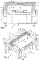
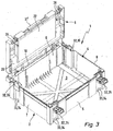
- the container 1 has a box-shaped or dish-shaped lower part 2 with a container bottom 3 and an open top side 4. From the container bottom 3 are a front wall 5, an opposite rear wall 6 and two side walls 7, 8 high, so that a substantially cuboid, open at the top interior is formed, in which the machine tool in question can be inserted.
- the open top 4 of the lower part 2 is assigned a Be fiscalerdekkel 9, with which the lower part 2 is closed ( FIGS. 1, 2 . 4 and 5 ) or opened ( FIG. 3 ) can be.
- the container lid 9 is articulated in the region of the rear wall 6 on the lower part 2 in the present not further interesting manner.
- the associated Anlenkachsline 10 is in FIG. 3 ' indicated by dotted lines.
- a carrying handle 11 is arranged, which has a U-like shape with a support web 12 and two spaced apart from the support web 12 projecting retaining legs 13, 14.
- the holding legs 13, 14 are respectively pivotally mounted with their their in the support web 12 opposite end portion 15, 16 the Schwenkachslinien 17, 18 on the container lid 9, so that the carrying handle 11 between a resting on the container lid 9 non-use position ( Figures 2 and 3 ) and an upstanding from the container lid 9 carrying position ( FIG. 1 ) is pivotable, in which the user can grab the support bar 12 and thus can carry the container 1.
- the carrying handle extends in the direction of the Anlenkachsline 10 parallel longitudinal direction 19 of the container lid 9, d. H. the Schwenkachsline 17, 18 is parallel to the Anlenkachsline 10. Rectangular to the longitudinal direction 19 seen is the Schwenkachsline 17, 18 of the handle 11 in half the width of the container lid. 9
- the carrying handle 11 is recessed in its non-use position with respect to the top of the container lid 9 in the Be Daveerdekkel 9. This is particularly advantageous in connection with the fact that a plurality of containers 1 are stackable and releasably firmly connected to one another, as will be described.
- the container lid 9 has recessed at the location of the carrying handle 11 according to the carrying handle thickness Lid section 20 which receives the carrying handle 11 in its non-use position.
- the recessed lid portion 20 is in FIG. 3 visible from below.
- the arrangement is further suitably made such that the carrying handle 11, starting from its carrying position, is pivotable in one direction only to its non-use position.
- the non-use position as from the Figures 2 and 4 can be seen, the rear wall 6 of the lower part 2 facing.
- a receiving space 21 for receiving accessories and / or other parts is arranged, which the user needs when performing his work with the machine if necessary.
- the receiving space 21 may, as shown in Figure 4, be divided into variable compartments. In Figure 3, the container lid 9 and thus the bottom surface 22 of the receiving space 21 is visible from below.
- the receiving space 21 is open at the top of the container lid 9.
- a closure lid 23 is associated with the receiving space 21, which closes between a closing position closing the receiving space 21 and an open position (FIG. 3) allowing the access to the receiving space 21 (FIG. FIG. 4 ) is movable and expediently pivoted on the container lid 9 is arranged.
- the receiving space 21 is expediently formed by a recess formed in the container lid 9.
- the container lid 9 can be produced as a plastic molded part, so that with the receiving space 21 no special manufacturing effort is connected.
- the closure lid 23 is shaped and arranged so that it is partially enclosed in the plan view in the non-use position of the carrying handle 11 by the carrying handle 11.
- the carrying handle 11 has, as already mentioned, a U-like shape and lies in its non-use position in or parallel to the plane of the container lid 9, so that it encloses with its supporting web 12 and its retaining legs 13, 14, an area of a cap portion 24 is taken.
- the closure lid 23 engages with its closure lid part 24, so to speak, in the U formed by the carrying handle 11.
- the closure lid member 24 is suitably contoured according to the course of the inside 25 of the carrying handle 11 and at least substantially fills out the area encompassed by the carrying handle 11.
- the receiving space 21 is substantially the same size as the closure lid 23 when viewed in the area.
- closure cap 23 expediently has a square or rectangular shape.
- the closure lid 23 is in the non-use position of the carrying handle 11 on the support web 12 opposite side of the carrying handle 11 before.
- the closure lid 23 is arranged pivotably on the container lid 9. This could be different in principle.
- the closure lid 23 is expediently with his in the Non-use position of the carrying handle 11 the support web 12 facing region pivotally connected to the container lid 9.
- a laterally projecting bearing pin 26, 27 can be present on the closure lid 23 at the rear on both sides of the closure lid, which engages in a bearing recess arranged on the container lid 9, so that a hinge axis 28 is formed around which the closure lid 23 can be pivoted.
- the closure lid 23 extends in its closed position in the direction of the support web 12 of the carrying handle 11 away conveniently to the front wall 5 of the lower part 2 adjacent the front container lid edge portion 29.
- the receiving space 21 is correspondingly large.
- the closure lid 23 is releasably latched in its closed position with the container lid 9. In principle, locking or otherwise fixing would be possible.
- the latching takes place by means of a latching device 31 which is arranged on the front cover cover edge region 30 and is associated with a mating latching device 31 'on the container cover edge region 29 facing.
- the latching device 31 can be formed, for example, by a latching projection and the mating latching device 31 'by an upstanding, elastically bendable latching web with an inwardly directed latching lug.
- a latching projection When closing the closure lid 23 of the latching web is deflected by the latching projection elastically until the latching projection engages behind the latching nose and the latching web snaps back into its starting position.
- To release the locking can bend the locking bar by hand elastically, so that the locking projection comes free.
- Such locking devices are in great variety well known. A more detailed description should therefore be unnecessary.
- closure cap 23 is arranged in its closed position in or below the plane of the top of the container lid 9. This is likewise advantageous in connection with the fact that a plurality of containers 1 can be stacked on one another and detachably connected to one another in the stacked state, so that the stacked containers 1 form a firmly connected unit which can be carried on the carrying handle 11 of the uppermost container 1. In FIG. 5 two stacked container 1 are shown.
- each container 1 has on its outer side in its upper region a plurality of circumferentially spaced upper connecting means 32 and in its lower region a plurality of appropriately distributed arranged lower connecting means 33.
- the arrangement is such that the upper connecting means 32 of the respective lower container 1 with the lower connecting means 33 of the respective upper container 1 are detachably connectable.
- the upper connecting means 32 as the lower connecting means 33 are arranged on the container base 2, so that the stacked containers 1 without the participation of the container lid 9 of the respective lower container 1 with their lower parts 2 are fastened together.
- the upper connecting means 32 are arranged adjustable in height. In the upwardly adjusted state, the in FIG. 5 indicated dotted, they protrude above the container lid 9 and extend to the lower connecting means 33 of the upper container 1 and can be brought into engagement therewith.
- the lower connecting means 33 may be formed by outwardly projecting locking pin 34.
- the upper connecting means 32 may have pivotally arranged latching parts 35 with locking recesses on its inner side. To connect the container, the appropriately far upwardly Verrastungsmaschine 35 of the lower container 1 are snapped with their recesses on the locking pin 34 of the upper container 1.
- further connecting means 36 for example, also in the form of locking pin, be arranged so that you latched at not stacked container 1 arranged on the lower part 2 Verrastungsmaschine 35 on the other connecting means 36 of the same container and thus the container lid 9 in his Closed position on the lower part 2 can fix. It is understood that in this case the Verrastungsmaschine 35 are adjusted accordingly far down.
- connection means - fastening stacked containers to one another and fastening the container lid 9 to the lower part 2 of a single container - are known per se and are described, for example, in US Pat EP 0 555 533 B1 described in detail. For further details, reference is therefore made to this document.
Landscapes
- Engineering & Computer Science (AREA)
- Mechanical Engineering (AREA)
- Stackable Containers (AREA)
- Details Of Rigid Or Semi-Rigid Containers (AREA)
- Closures For Containers (AREA)
Claims (16)
- Récipient de type coffre, en particulier pour la réception de machinesoutils transportables, avec une partie inférieure (2) en forme de boîte ou coque et un couvercle de récipient (9) associé au côté supérieur ouvert (4) de la partie inférieure (2), sur le côté supérieur duquel une poignée (11) est agencée, laquelle présente une forme en U avec une nervure porteuse (12) et deux branches de retenue (13, 14) dépassant à distance l'une de l'autre de la nervure porteuse (12), les branches de retenue (13, 14) étant logées avec leurs zones d'extrémité (15, 16) en regard de la nervure porteuse (12) de manière à pouvoir pivoter sur le couvercle de récipient (9) de sorte que la poignée (11) puisse être pivotée entre une position de non utilisation reposant sur le couvercle de récipient (9) et une position de support surélevée du couvercle de récipient (9), et un espace de réception (21) ouvert sur le côté supérieur de couvercle de récipient étant agencé sur le couvercle de récipient (9) pour des accessoires et/ou autres pièces, en particulier petites pièces avec un couvercle de fermeture (23) associé, pouvant se déplacer entre une position de fermeture fermant l'espace de réception (21) et une position ouverte permettant l'accès à l'espace de réception (21), l'espace de réception (21) et le couvercle de fermeture (23) étant entourés dans la vue en élévation dans la position de non-utilisation de la poignée (11) en partie par la poignée (11) en s'engageant dans le U formé par la poignée (11).
- Récipient selon la revendication 1, caractérisé en ce que l'espace de réception (21) est formé par une cavité réalisée dans le couvercle de récipient (9).
- Récipient selon la revendication 1 ou 2, caractérisé en ce que la partie de couvercle de fermeture (24) entourée par la poignée (11) dans sa position de non-utilisation et la section se trouvant dans le U de la poignée (11) de l'espace de réception (21) présentent un contour correspondant à l'étendue du côté intérieur (25) de la poignée (11) et remplissent au moins sensiblement la surface entourée par la poignée (11).
- Récipient selon l'une quelconque des revendications 1 à 3, caractérisé en ce que la poignée (11) peut pivoter à partir de sa position porteuse seulement dans un sens jusque dans sa position de non-utilisation.
- Récipient selon l'une quelconque des revendications 1 à 4, caractérisé en ce que la nervure porteuse (12) de la poignée (11) s'étend dans le sens longitudinal (19) du couvercle de récipient (9) et la poignée (11) est logée de manière à pouvoir pivoter autour d'une ligne axiale de pivotement (17, 18) s'étendant dans la demi-largeur du couvercle de récipient (11) dans le sens longitudinal (19) du couvercle de récipient (9) sur le couvercle de récipient (9).
- Récipient selon l'une quelconque des revendications 1 à 5, caractérisé en ce que le couvercle de fermeture (23) et l'espace de réception (21) présentent une forme carrée ou rectangulaire.
- Récipient selon l'une quelconque des revendications 1 à 6, caractérisé en ce que dans la position de non-utilisation de la poignée (11), le couvercle de fermeture (23) et l'espace de réception (21) dépassent, sur le côté en regard de la nervure porteuse (12), du U de la poignée (11).
- Récipient selon l'une quelconque des revendications 1 à 7, caractérisé en ce que le couvercle de fermeture (23) est agencé de manière à pouvoir pivoter entre sa position de fermeture et sa position ouverte sur le couvercle de récipient (9).
- Récipient selon la revendication 8, caractérisé en ce que le couvercle de fermeture (23) est relié de manière pivotante au couvercle de récipient (9) avec sa zone tournée dans la position de non-utilisation de la poignée (11) vers la nervure porteuse (12).
- Récipient selon l'une quelconque des revendications 1 à 9, caractérisé en ce que le couvercle de fermeture (23) s'étend jusqu'à la zone de bord de couvercle de récipient (29).
- Récipient selon l'une quelconque des revendications 8 à 10, caractérisé en ce que le couvercle de fermeture (23) peut être encliqueté de manière détachable dans sa position de fermeture avec le couvercle de récipient (9).
- Récipient selon la revendication 11, caractérisé en ce que le couvercle de fermeture (23) est relié d'une part de manière à pouvoir pivoter au couvercle de récipient (9) et présente d'autre part sur sa zone de bord de couvercle de fermeture (30) en regard un dispositif d'encliquetage (31), auquel est associé un dispositif d'encliquetage antagoniste (31') sur la zone de bord de couvercle de récipient (29) tournée.
- Récipient selon l'une quelconque des revendications 1 à 12, caractérisé en ce que le couvercle de fermeture (23) est agencé dans sa position de fermeture dans ou en dessous du plan du côté supérieur du couvercle de récipient (9).
- Récipient selon l'une quelconque des revendications 1 à 13, caractérisé en ce que la poignée (11) est agencée dans sa position de non-utilisation en ce qui concerne le côté supérieur du couvercle de récipient de manière noyée dans le couvercle de récipient (9).
- Récipient selon l'une quelconque des revendications 1 à 14, caractérisé en ce qu'il présente des moyens de liaison (32) supérieurs agencés sur son côté extérieur dans sa zone supérieure et des moyens de liaison (33) inférieurs agencés dans sa zone inférieure de telle manière que plusieurs récipients (1) soient empilables les uns sur les autres et puissent être reliés fixement entre eux de manière détachable en ce que les moyens de liaison supérieurs (32) du récipient respectivement inférieur (1) sont reliés de manière détachable aux moyens de liaison (33) inférieurs du récipient respectivement supérieur (1).
- Récipient selon la revendication 15, caractérisé en ce que les moyens de liaison inférieurs (33) et les moyens de liaison supérieurs (32) sont agencés sur la partie inférieure de récipient (2).
Priority Applications (5)
| Application Number | Priority Date | Filing Date | Title |
|---|---|---|---|
| PL07014964.6T PL2020188T3 (pl) | 2007-07-31 | 2007-07-31 | Kufrowy pojemnik, zwłaszcza do przyjmowania transportowalnych obrabiarek |
| EP07014964.6A EP2020188B1 (fr) | 2007-07-31 | 2007-07-31 | Récipient de type coffre, en particulier pour la réception de machines-outils transportables |
| DK07014964.6T DK2020188T3 (en) | 2007-07-31 | 2007-07-31 | Suitcase like container, in particular for receiving portable tools |
| HUE07014964A HUE029034T2 (en) | 2007-07-31 | 2007-07-31 | Off-the-shelf storage device, mainly for transporting machine tools |
| ES07014964.6T ES2573472T3 (es) | 2007-07-31 | 2007-07-31 | Recipiente de tipo maleta, en particular para el alojamiento de máquinas-herramienta portátiles |
Applications Claiming Priority (1)
| Application Number | Priority Date | Filing Date | Title |
|---|---|---|---|
| EP07014964.6A EP2020188B1 (fr) | 2007-07-31 | 2007-07-31 | Récipient de type coffre, en particulier pour la réception de machines-outils transportables |
Publications (2)
| Publication Number | Publication Date |
|---|---|
| EP2020188A1 EP2020188A1 (fr) | 2009-02-04 |
| EP2020188B1 true EP2020188B1 (fr) | 2016-04-20 |
Family
ID=39167482
Family Applications (1)
| Application Number | Title | Priority Date | Filing Date |
|---|---|---|---|
| EP07014964.6A Active EP2020188B1 (fr) | 2007-07-31 | 2007-07-31 | Récipient de type coffre, en particulier pour la réception de machines-outils transportables |
Country Status (5)
| Country | Link |
|---|---|
| EP (1) | EP2020188B1 (fr) |
| DK (1) | DK2020188T3 (fr) |
| ES (1) | ES2573472T3 (fr) |
| HU (1) | HUE029034T2 (fr) |
| PL (1) | PL2020188T3 (fr) |
Cited By (2)
| Publication number | Priority date | Publication date | Assignee | Title |
|---|---|---|---|---|
| WO2023151821A1 (fr) | 2022-02-14 | 2023-08-17 | Tanos Gmbh | Dispositif de stockage |
| US11884456B2 (en) | 2020-09-25 | 2024-01-30 | Techtronic Cordless Gp | Tool storage system |
Families Citing this family (13)
| Publication number | Priority date | Publication date | Assignee | Title |
|---|---|---|---|---|
| WO2011000387A1 (fr) * | 2009-06-29 | 2011-01-06 | Tts Tooltechnic Systems Ag & Co. Kg | Système de contenants empilables à verrouillage mutuel des contenants empilés |
| CA2735679C (fr) * | 2009-06-29 | 2016-08-23 | Tts Tooltechnic Systems Ag & Co. Kg | Systeme de contenants empilables a verrouillage mutuel des contenants empiles |
| EP2296989B1 (fr) | 2009-06-29 | 2016-11-23 | TTS Tooltechnic Systems AG & Co. KG | Contenant portatif |
| USD638179S1 (en) | 2009-08-31 | 2011-05-17 | Witter Robert M | Auxiliary cyclonic dust collector |
| ES2660163T3 (es) | 2009-09-15 | 2018-03-21 | Tts Tooltechnic Systems Ag & Co. Kg | Disposición de contenedor |
| DE102011108416A1 (de) * | 2011-07-26 | 2013-01-31 | Tts Tooltechnic Systems Ag & Co. Kg | Tragbarer Behälter |
| DE102014118452A1 (de) * | 2014-12-11 | 2016-06-16 | Adolf Würth GmbH & Co. KG | Koffer |
| DE102016112853A1 (de) * | 2016-07-13 | 2018-01-18 | Bs Systems Gmbh & Co. Kg | Stapelbarer Systembehälter |
| DE102016112854A1 (de) | 2016-07-13 | 2018-01-18 | Bs Systems Gmbh & Co. Kg | Stapelbarer Systembehälter |
| DE102016112855A1 (de) | 2016-07-13 | 2018-01-18 | Bs Systems Gmbh & Co. Kg | Stapelbarer Systembehälter |
| DE102017128493B3 (de) | 2017-11-30 | 2018-08-16 | Bs Systems Gmbh & Co. Kg | Stapelbarer Systembehälter und Transportsystem |
| USD918580S1 (en) | 2018-08-07 | 2021-05-11 | Bs Systems Gmbh & Co. Kg | Transport case |
| DE102020104512B3 (de) | 2020-02-20 | 2021-01-07 | Bs Systems Gmbh & Co. Kg | Gürteladapter und Haltesystem umfassend einen Gürteladapter und ein Trägerelement |
Family Cites Families (6)
| Publication number | Priority date | Publication date | Assignee | Title |
|---|---|---|---|---|
| DE4201264A1 (de) * | 1992-01-18 | 1993-07-22 | Festo Kg | Stapelbarer koffer |
| US5553712A (en) | 1995-05-05 | 1996-09-10 | Suncast Corporation | Trading card carrying and display case |
| US5826718A (en) * | 1997-06-20 | 1998-10-27 | Rubbermaid Incorporated | Tool box with bin-carrying cover |
| US20030106821A1 (en) | 2001-06-14 | 2003-06-12 | Zag Industries, Ltd. | Toolbox with external compartment |
| US7334680B2 (en) * | 2003-01-15 | 2008-02-26 | Irwin Industrial Tool Company | Modular toolbox system |
| US20050236290A1 (en) * | 2004-04-21 | 2005-10-27 | One World Technologies Limited. | Case with removable accessory holder |
-
2007
- 2007-07-31 DK DK07014964.6T patent/DK2020188T3/en active
- 2007-07-31 ES ES07014964.6T patent/ES2573472T3/es active Active
- 2007-07-31 EP EP07014964.6A patent/EP2020188B1/fr active Active
- 2007-07-31 PL PL07014964.6T patent/PL2020188T3/pl unknown
- 2007-07-31 HU HUE07014964A patent/HUE029034T2/en unknown
Cited By (2)
| Publication number | Priority date | Publication date | Assignee | Title |
|---|---|---|---|---|
| US11884456B2 (en) | 2020-09-25 | 2024-01-30 | Techtronic Cordless Gp | Tool storage system |
| WO2023151821A1 (fr) | 2022-02-14 | 2023-08-17 | Tanos Gmbh | Dispositif de stockage |
Also Published As
| Publication number | Publication date |
|---|---|
| ES2573472T3 (es) | 2016-06-08 |
| PL2020188T3 (pl) | 2016-10-31 |
| EP2020188A1 (fr) | 2009-02-04 |
| DK2020188T3 (en) | 2016-08-01 |
| HUE029034T2 (en) | 2017-01-30 |
Similar Documents
| Publication | Publication Date | Title |
|---|---|---|
| EP2020188B1 (fr) | Récipient de type coffre, en particulier pour la réception de machines-outils transportables | |
| EP3484665B1 (fr) | Contenant modulaire empilable | |
| EP2994274B1 (fr) | Agencement de récipient | |
| EP3294501B1 (fr) | Dispositif de rangement | |
| EP2805799B1 (fr) | Récipient portatif, en particulier pour une machine-outil manuelle | |
| EP2703310A1 (fr) | Récipient | |
| EP1516703A1 (fr) | Boíte à outils empilable | |
| EP1238602B1 (fr) | Valise empilable à accrochage rapide | |
| DE102009024043A1 (de) | Zusammenlegbarer Behälter | |
| DE3407043A1 (de) | Verpackungsbehaelter | |
| WO2011000386A1 (fr) | Contenant portatif | |
| DE10359266A1 (de) | Werkzeugkasten für mehrere Anordnungen | |
| DE102011108416A1 (de) | Tragbarer Behälter | |
| DE202016103774U1 (de) | Stapelbarer Systembehälter | |
| EP3024622B1 (fr) | Systeme de transport avec conteneur | |
| DE202006010567U1 (de) | Werkzeugkoffer | |
| DE354937C (de) | Tragbarer Werkzeugkasten | |
| DE4304160A1 (de) | Transportbehälter | |
| DE202016004104U1 (de) | Werkzeugbox | |
| EP2055443B1 (fr) | Réservoir de transport et unité de vente dotée d'un double emballage et d'une réception d'outil avec au moins un outil | |
| DE4006782A1 (de) | Kassette zur aufbewahrung von gegenstaenden | |
| DE202012002824U1 (de) | Werkzeugkoffer | |
| DE102012005523A1 (de) | Werkzeugkoffer | |
| DE19633341A1 (de) | Zusammenklappbare Werkbank | |
| DE20122840U1 (de) | Aufbewahrungsvorrichtung mit mehreren Werkzeugen |
Legal Events
| Date | Code | Title | Description |
|---|---|---|---|
| PUAI | Public reference made under article 153(3) epc to a published international application that has entered the european phase |
Free format text: ORIGINAL CODE: 0009012 |
|
| AK | Designated contracting states |
Kind code of ref document: A1 Designated state(s): AT BE BG CH CY CZ DE DK EE ES FI FR GB GR HU IE IS IT LI LT LU LV MC MT NL PL PT RO SE SI SK TR |
|
| AX | Request for extension of the european patent |
Extension state: AL BA HR MK RS |
|
| 17P | Request for examination filed |
Effective date: 20090207 |
|
| 17Q | First examination report despatched |
Effective date: 20090316 |
|
| AKX | Designation fees paid |
Designated state(s): AT BE BG CH CY CZ DE DK EE ES FI FR GB GR HU IE IS IT LI LT LU LV MC MT NL PL PT RO SE SI SK TR |
|
| REG | Reference to a national code |
Ref country code: DE Ref legal event code: R079 Ref document number: 502007014737 Country of ref document: DE Free format text: PREVIOUS MAIN CLASS: A45C0013020000 Ipc: A45C0005060000 |
|
| GRAP | Despatch of communication of intention to grant a patent |
Free format text: ORIGINAL CODE: EPIDOSNIGR1 |
|
| RIC1 | Information provided on ipc code assigned before grant |
Ipc: A45C 13/26 20060101ALI20151027BHEP Ipc: B25H 3/02 20060101ALI20151027BHEP Ipc: A45C 5/06 20060101AFI20151027BHEP Ipc: B65D 21/02 20060101ALI20151027BHEP Ipc: A45C 13/02 20060101ALN20151027BHEP |
|
| INTG | Intention to grant announced |
Effective date: 20151112 |
|
| GRAS | Grant fee paid |
Free format text: ORIGINAL CODE: EPIDOSNIGR3 |
|
| GRAA | (expected) grant |
Free format text: ORIGINAL CODE: 0009210 |
|
| AK | Designated contracting states |
Kind code of ref document: B1 Designated state(s): AT BE BG CH CY CZ DE DK EE ES FI FR GB GR HU IE IS IT LI LT LU LV MC MT NL PL PT RO SE SI SK TR |
|
| REG | Reference to a national code |
Ref country code: GB Ref legal event code: FG4D Free format text: NOT ENGLISH |
|
| REG | Reference to a national code |
Ref country code: CH Ref legal event code: NV Representative=s name: TSWPAT LUZERN AG, CH Ref country code: CH Ref legal event code: EP |
|
| REG | Reference to a national code |
Ref country code: AT Ref legal event code: REF Ref document number: 791365 Country of ref document: AT Kind code of ref document: T Effective date: 20160515 |
|
| REG | Reference to a national code |
Ref country code: IE Ref legal event code: FG4D Free format text: LANGUAGE OF EP DOCUMENT: GERMAN |
|
| REG | Reference to a national code |
Ref country code: DE Ref legal event code: R096 Ref document number: 502007014737 Country of ref document: DE |
|
| REG | Reference to a national code |
Ref country code: ES Ref legal event code: FG2A Ref document number: 2573472 Country of ref document: ES Kind code of ref document: T3 Effective date: 20160608 |
|
| REG | Reference to a national code |
Ref country code: FR Ref legal event code: PLFP Year of fee payment: 10 |
|
| REG | Reference to a national code |
Ref country code: DK Ref legal event code: T3 Effective date: 20160722 |
|
| REG | Reference to a national code |
Ref country code: SE Ref legal event code: TRGR |
|
| REG | Reference to a national code |
Ref country code: NL Ref legal event code: FP |
|
| REG | Reference to a national code |
Ref country code: LT Ref legal event code: MG4D |
|
| PG25 | Lapsed in a contracting state [announced via postgrant information from national office to epo] |
Ref country code: LT Free format text: LAPSE BECAUSE OF FAILURE TO SUBMIT A TRANSLATION OF THE DESCRIPTION OR TO PAY THE FEE WITHIN THE PRESCRIBED TIME-LIMIT Effective date: 20160420 |
|
| PG25 | Lapsed in a contracting state [announced via postgrant information from national office to epo] |
Ref country code: GR Free format text: LAPSE BECAUSE OF FAILURE TO SUBMIT A TRANSLATION OF THE DESCRIPTION OR TO PAY THE FEE WITHIN THE PRESCRIBED TIME-LIMIT Effective date: 20160721 Ref country code: LV Free format text: LAPSE BECAUSE OF FAILURE TO SUBMIT A TRANSLATION OF THE DESCRIPTION OR TO PAY THE FEE WITHIN THE PRESCRIBED TIME-LIMIT Effective date: 20160420 Ref country code: PT Free format text: LAPSE BECAUSE OF FAILURE TO SUBMIT A TRANSLATION OF THE DESCRIPTION OR TO PAY THE FEE WITHIN THE PRESCRIBED TIME-LIMIT Effective date: 20160822 |
|
| REG | Reference to a national code |
Ref country code: DE Ref legal event code: R097 Ref document number: 502007014737 Country of ref document: DE |
|
| REG | Reference to a national code |
Ref country code: HU Ref legal event code: AG4A Ref document number: E029034 Country of ref document: HU |
|
| PG25 | Lapsed in a contracting state [announced via postgrant information from national office to epo] |
Ref country code: RO Free format text: LAPSE BECAUSE OF FAILURE TO SUBMIT A TRANSLATION OF THE DESCRIPTION OR TO PAY THE FEE WITHIN THE PRESCRIBED TIME-LIMIT Effective date: 20160420 Ref country code: EE Free format text: LAPSE BECAUSE OF FAILURE TO SUBMIT A TRANSLATION OF THE DESCRIPTION OR TO PAY THE FEE WITHIN THE PRESCRIBED TIME-LIMIT Effective date: 20160420 Ref country code: SK Free format text: LAPSE BECAUSE OF FAILURE TO SUBMIT A TRANSLATION OF THE DESCRIPTION OR TO PAY THE FEE WITHIN THE PRESCRIBED TIME-LIMIT Effective date: 20160420 |
|
| PLBE | No opposition filed within time limit |
Free format text: ORIGINAL CODE: 0009261 |
|
| STAA | Information on the status of an ep patent application or granted ep patent |
Free format text: STATUS: NO OPPOSITION FILED WITHIN TIME LIMIT |
|
| 26N | No opposition filed |
Effective date: 20170123 |
|
| PG25 | Lapsed in a contracting state [announced via postgrant information from national office to epo] |
Ref country code: MC Free format text: LAPSE BECAUSE OF FAILURE TO SUBMIT A TRANSLATION OF THE DESCRIPTION OR TO PAY THE FEE WITHIN THE PRESCRIBED TIME-LIMIT Effective date: 20160420 |
|
| REG | Reference to a national code |
Ref country code: IE Ref legal event code: MM4A |
|
| PG25 | Lapsed in a contracting state [announced via postgrant information from national office to epo] |
Ref country code: SI Free format text: LAPSE BECAUSE OF FAILURE TO SUBMIT A TRANSLATION OF THE DESCRIPTION OR TO PAY THE FEE WITHIN THE PRESCRIBED TIME-LIMIT Effective date: 20160420 |
|
| REG | Reference to a national code |
Ref country code: FR Ref legal event code: PLFP Year of fee payment: 11 |
|
| PG25 | Lapsed in a contracting state [announced via postgrant information from national office to epo] |
Ref country code: IE Free format text: LAPSE BECAUSE OF NON-PAYMENT OF DUE FEES Effective date: 20160731 |
|
| PG25 | Lapsed in a contracting state [announced via postgrant information from national office to epo] |
Ref country code: LU Free format text: LAPSE BECAUSE OF NON-PAYMENT OF DUE FEES Effective date: 20160731 |
|
| PG25 | Lapsed in a contracting state [announced via postgrant information from national office to epo] |
Ref country code: CY Free format text: LAPSE BECAUSE OF FAILURE TO SUBMIT A TRANSLATION OF THE DESCRIPTION OR TO PAY THE FEE WITHIN THE PRESCRIBED TIME-LIMIT Effective date: 20160420 |
|
| PG25 | Lapsed in a contracting state [announced via postgrant information from national office to epo] |
Ref country code: MT Free format text: LAPSE BECAUSE OF FAILURE TO SUBMIT A TRANSLATION OF THE DESCRIPTION OR TO PAY THE FEE WITHIN THE PRESCRIBED TIME-LIMIT Effective date: 20160420 Ref country code: TR Free format text: LAPSE BECAUSE OF FAILURE TO SUBMIT A TRANSLATION OF THE DESCRIPTION OR TO PAY THE FEE WITHIN THE PRESCRIBED TIME-LIMIT Effective date: 20160420 Ref country code: IS Free format text: LAPSE BECAUSE OF FAILURE TO SUBMIT A TRANSLATION OF THE DESCRIPTION OR TO PAY THE FEE WITHIN THE PRESCRIBED TIME-LIMIT Effective date: 20160420 |
|
| REG | Reference to a national code |
Ref country code: FR Ref legal event code: PLFP Year of fee payment: 12 |
|
| PG25 | Lapsed in a contracting state [announced via postgrant information from national office to epo] |
Ref country code: BG Free format text: LAPSE BECAUSE OF FAILURE TO SUBMIT A TRANSLATION OF THE DESCRIPTION OR TO PAY THE FEE WITHIN THE PRESCRIBED TIME-LIMIT Effective date: 20160420 |
|
| PGFP | Annual fee paid to national office [announced via postgrant information from national office to epo] |
Ref country code: ES Payment date: 20190822 Year of fee payment: 13 Ref country code: CZ Payment date: 20190723 Year of fee payment: 13 Ref country code: DK Payment date: 20190723 Year of fee payment: 13 Ref country code: FI Payment date: 20190719 Year of fee payment: 13 |
|
| PGFP | Annual fee paid to national office [announced via postgrant information from national office to epo] |
Ref country code: HU Payment date: 20190717 Year of fee payment: 13 |
|
| PGFP | Annual fee paid to national office [announced via postgrant information from national office to epo] |
Ref country code: AT Payment date: 20190719 Year of fee payment: 13 |
|
| PGFP | Annual fee paid to national office [announced via postgrant information from national office to epo] |
Ref country code: CH Payment date: 20190725 Year of fee payment: 13 |
|
| REG | Reference to a national code |
Ref country code: CH Ref legal event code: PFUS Owner name: TTS TOOLTECHNIC SYSTEMS AG AND CO. KG, DE Free format text: FORMER OWNER: TTS TOOLTECHNIC SYSTEMS AG AND CO. KG, DE |
|
| REG | Reference to a national code |
Ref country code: FI Ref legal event code: MAE |
|
| REG | Reference to a national code |
Ref country code: CH Ref legal event code: PL |
|
| REG | Reference to a national code |
Ref country code: DK Ref legal event code: EBP Effective date: 20200731 |
|
| REG | Reference to a national code |
Ref country code: AT Ref legal event code: MM01 Ref document number: 791365 Country of ref document: AT Kind code of ref document: T Effective date: 20200731 |
|
| PG25 | Lapsed in a contracting state [announced via postgrant information from national office to epo] |
Ref country code: FI Free format text: LAPSE BECAUSE OF NON-PAYMENT OF DUE FEES Effective date: 20200731 Ref country code: LI Free format text: LAPSE BECAUSE OF NON-PAYMENT OF DUE FEES Effective date: 20200731 Ref country code: HU Free format text: LAPSE BECAUSE OF NON-PAYMENT OF DUE FEES Effective date: 20200801 Ref country code: CH Free format text: LAPSE BECAUSE OF NON-PAYMENT OF DUE FEES Effective date: 20200731 Ref country code: CZ Free format text: LAPSE BECAUSE OF NON-PAYMENT OF DUE FEES Effective date: 20200731 |
|
| PG25 | Lapsed in a contracting state [announced via postgrant information from national office to epo] |
Ref country code: AT Free format text: LAPSE BECAUSE OF NON-PAYMENT OF DUE FEES Effective date: 20200731 |
|
| PG25 | Lapsed in a contracting state [announced via postgrant information from national office to epo] |
Ref country code: DK Free format text: LAPSE BECAUSE OF NON-PAYMENT OF DUE FEES Effective date: 20200731 |
|
| REG | Reference to a national code |
Ref country code: ES Ref legal event code: FD2A Effective date: 20220103 |
|
| PG25 | Lapsed in a contracting state [announced via postgrant information from national office to epo] |
Ref country code: ES Free format text: LAPSE BECAUSE OF NON-PAYMENT OF DUE FEES Effective date: 20200801 |
|
| P01 | Opt-out of the competence of the unified patent court (upc) registered |
Effective date: 20230519 |
|
| PGFP | Annual fee paid to national office [announced via postgrant information from national office to epo] |
Ref country code: PL Payment date: 20230629 Year of fee payment: 17 Ref country code: NL Payment date: 20230720 Year of fee payment: 17 |
|
| PGFP | Annual fee paid to national office [announced via postgrant information from national office to epo] |
Ref country code: IT Payment date: 20230731 Year of fee payment: 17 Ref country code: GB Payment date: 20230724 Year of fee payment: 17 |
|
| PGFP | Annual fee paid to national office [announced via postgrant information from national office to epo] |
Ref country code: SE Payment date: 20230724 Year of fee payment: 17 Ref country code: FR Payment date: 20230724 Year of fee payment: 17 Ref country code: DE Payment date: 20230512 Year of fee payment: 17 Ref country code: BE Payment date: 20230719 Year of fee payment: 17 |